EP2456043B1 - Power consumption compliance monitoring system and method - Google Patents
Power consumption compliance monitoring system and method Download PDFInfo
- Publication number
- EP2456043B1 EP2456043B1 EP11188866.5A EP11188866A EP2456043B1 EP 2456043 B1 EP2456043 B1 EP 2456043B1 EP 11188866 A EP11188866 A EP 11188866A EP 2456043 B1 EP2456043 B1 EP 2456043B1
- Authority
- EP
- European Patent Office
- Prior art keywords
- load
- power
- consumer
- profile
- power usage
- Prior art date
- Legal status (The legal status is an assumption and is not a legal conclusion. Google has not performed a legal analysis and makes no representation as to the accuracy of the status listed.)
- Active
Links
- 238000000034 method Methods 0.000 title claims description 20
- 238000012544 monitoring process Methods 0.000 title description 6
- 238000004891 communication Methods 0.000 claims description 19
- 238000003860 storage Methods 0.000 claims description 17
- 238000012545 processing Methods 0.000 claims description 5
- 238000004590 computer program Methods 0.000 claims description 4
- 239000013598 vector Substances 0.000 claims description 3
- 230000004044 response Effects 0.000 description 90
- 238000005070 sampling Methods 0.000 description 5
- 238000012795 verification Methods 0.000 description 5
- 238000004519 manufacturing process Methods 0.000 description 4
- 230000008901 benefit Effects 0.000 description 3
- 238000010586 diagram Methods 0.000 description 3
- 230000000694 effects Effects 0.000 description 3
- 230000007935 neutral effect Effects 0.000 description 3
- 230000005540 biological transmission Effects 0.000 description 2
- 230000001413 cellular effect Effects 0.000 description 2
- 230000008859 change Effects 0.000 description 2
- 238000013461 design Methods 0.000 description 2
- 238000011161 development Methods 0.000 description 2
- 238000005265 energy consumption Methods 0.000 description 2
- 230000003287 optical effect Effects 0.000 description 2
- 238000009825 accumulation Methods 0.000 description 1
- 238000004378 air conditioning Methods 0.000 description 1
- 238000013459 approach Methods 0.000 description 1
- 238000004364 calculation method Methods 0.000 description 1
- 239000003990 capacitor Substances 0.000 description 1
- 238000010411 cooking Methods 0.000 description 1
- 238000007599 discharging Methods 0.000 description 1
- 230000006870 function Effects 0.000 description 1
- 238000010438 heat treatment Methods 0.000 description 1
- 239000004973 liquid crystal related substance Substances 0.000 description 1
- 230000002093 peripheral effect Effects 0.000 description 1
- 238000003825 pressing Methods 0.000 description 1
- 238000009423 ventilation Methods 0.000 description 1
Images

Classifications
-
- G—PHYSICS
- G01—MEASURING; TESTING
- G01R—MEASURING ELECTRIC VARIABLES; MEASURING MAGNETIC VARIABLES
- G01R21/00—Arrangements for measuring electric power or power factor
- G01R21/133—Arrangements for measuring electric power or power factor by using digital technique
- G01R21/1333—Arrangements for measuring electric power or power factor by using digital technique adapted for special tariff measuring
-
- H—ELECTRICITY
- H02—GENERATION; CONVERSION OR DISTRIBUTION OF ELECTRIC POWER
- H02J—CIRCUIT ARRANGEMENTS OR SYSTEMS FOR SUPPLYING OR DISTRIBUTING ELECTRIC POWER; SYSTEMS FOR STORING ELECTRIC ENERGY
- H02J13/00—Circuit arrangements for providing remote indication of network conditions, e.g. an instantaneous record of the open or closed condition of each circuitbreaker in the network; Circuit arrangements for providing remote control of switching means in a power distribution network, e.g. switching in and out of current consumers by using a pulse code signal carried by the network
- H02J13/00002—Circuit arrangements for providing remote indication of network conditions, e.g. an instantaneous record of the open or closed condition of each circuitbreaker in the network; Circuit arrangements for providing remote control of switching means in a power distribution network, e.g. switching in and out of current consumers by using a pulse code signal carried by the network characterised by monitoring
-
- H—ELECTRICITY
- H02—GENERATION; CONVERSION OR DISTRIBUTION OF ELECTRIC POWER
- H02J—CIRCUIT ARRANGEMENTS OR SYSTEMS FOR SUPPLYING OR DISTRIBUTING ELECTRIC POWER; SYSTEMS FOR STORING ELECTRIC ENERGY
- H02J13/00—Circuit arrangements for providing remote indication of network conditions, e.g. an instantaneous record of the open or closed condition of each circuitbreaker in the network; Circuit arrangements for providing remote control of switching means in a power distribution network, e.g. switching in and out of current consumers by using a pulse code signal carried by the network
- H02J13/00004—Circuit arrangements for providing remote indication of network conditions, e.g. an instantaneous record of the open or closed condition of each circuitbreaker in the network; Circuit arrangements for providing remote control of switching means in a power distribution network, e.g. switching in and out of current consumers by using a pulse code signal carried by the network characterised by the power network being locally controlled
-
- H—ELECTRICITY
- H02—GENERATION; CONVERSION OR DISTRIBUTION OF ELECTRIC POWER
- H02J—CIRCUIT ARRANGEMENTS OR SYSTEMS FOR SUPPLYING OR DISTRIBUTING ELECTRIC POWER; SYSTEMS FOR STORING ELECTRIC ENERGY
- H02J3/00—Circuit arrangements for ac mains or ac distribution networks
- H02J3/12—Circuit arrangements for ac mains or ac distribution networks for adjusting voltage in ac networks by changing a characteristic of the network load
- H02J3/14—Circuit arrangements for ac mains or ac distribution networks for adjusting voltage in ac networks by changing a characteristic of the network load by switching loads on to, or off from, network, e.g. progressively balanced loading
-
- H—ELECTRICITY
- H02—GENERATION; CONVERSION OR DISTRIBUTION OF ELECTRIC POWER
- H02J—CIRCUIT ARRANGEMENTS OR SYSTEMS FOR SUPPLYING OR DISTRIBUTING ELECTRIC POWER; SYSTEMS FOR STORING ELECTRIC ENERGY
- H02J2310/00—The network for supplying or distributing electric power characterised by its spatial reach or by the load
- H02J2310/10—The network having a local or delimited stationary reach
- H02J2310/12—The local stationary network supplying a household or a building
- H02J2310/14—The load or loads being home appliances
-
- Y—GENERAL TAGGING OF NEW TECHNOLOGICAL DEVELOPMENTS; GENERAL TAGGING OF CROSS-SECTIONAL TECHNOLOGIES SPANNING OVER SEVERAL SECTIONS OF THE IPC; TECHNICAL SUBJECTS COVERED BY FORMER USPC CROSS-REFERENCE ART COLLECTIONS [XRACs] AND DIGESTS
- Y02—TECHNOLOGIES OR APPLICATIONS FOR MITIGATION OR ADAPTATION AGAINST CLIMATE CHANGE
- Y02B—CLIMATE CHANGE MITIGATION TECHNOLOGIES RELATED TO BUILDINGS, e.g. HOUSING, HOUSE APPLIANCES OR RELATED END-USER APPLICATIONS
- Y02B70/00—Technologies for an efficient end-user side electric power management and consumption
- Y02B70/30—Systems integrating technologies related to power network operation and communication or information technologies for improving the carbon footprint of the management of residential or tertiary loads, i.e. smart grids as climate change mitigation technology in the buildings sector, including also the last stages of power distribution and the control, monitoring or operating management systems at local level
- Y02B70/3225—Demand response systems, e.g. load shedding, peak shaving
-
- Y—GENERAL TAGGING OF NEW TECHNOLOGICAL DEVELOPMENTS; GENERAL TAGGING OF CROSS-SECTIONAL TECHNOLOGIES SPANNING OVER SEVERAL SECTIONS OF THE IPC; TECHNICAL SUBJECTS COVERED BY FORMER USPC CROSS-REFERENCE ART COLLECTIONS [XRACs] AND DIGESTS
- Y04—INFORMATION OR COMMUNICATION TECHNOLOGIES HAVING AN IMPACT ON OTHER TECHNOLOGY AREAS
- Y04S—SYSTEMS INTEGRATING TECHNOLOGIES RELATED TO POWER NETWORK OPERATION, COMMUNICATION OR INFORMATION TECHNOLOGIES FOR IMPROVING THE ELECTRICAL POWER GENERATION, TRANSMISSION, DISTRIBUTION, MANAGEMENT OR USAGE, i.e. SMART GRIDS
- Y04S20/00—Management or operation of end-user stationary applications or the last stages of power distribution; Controlling, monitoring or operating thereof
- Y04S20/20—End-user application control systems
- Y04S20/222—Demand response systems, e.g. load shedding, peak shaving
-
- Y—GENERAL TAGGING OF NEW TECHNOLOGICAL DEVELOPMENTS; GENERAL TAGGING OF CROSS-SECTIONAL TECHNOLOGIES SPANNING OVER SEVERAL SECTIONS OF THE IPC; TECHNICAL SUBJECTS COVERED BY FORMER USPC CROSS-REFERENCE ART COLLECTIONS [XRACs] AND DIGESTS
- Y04—INFORMATION OR COMMUNICATION TECHNOLOGIES HAVING AN IMPACT ON OTHER TECHNOLOGY AREAS
- Y04S—SYSTEMS INTEGRATING TECHNOLOGIES RELATED TO POWER NETWORK OPERATION, COMMUNICATION OR INFORMATION TECHNOLOGIES FOR IMPROVING THE ELECTRICAL POWER GENERATION, TRANSMISSION, DISTRIBUTION, MANAGEMENT OR USAGE, i.e. SMART GRIDS
- Y04S20/00—Management or operation of end-user stationary applications or the last stages of power distribution; Controlling, monitoring or operating thereof
- Y04S20/20—End-user application control systems
- Y04S20/242—Home appliances
Definitions
- the subject matter disclosed herein relates to monitoring power consumption to verify compliance with a power consumption limitation agreement during a demand response event or agreed period of limited power consumption.
- HVAC heating, ventilation, and air conditioning
- Prior art power consumption monitoring systems are known from WO2010/007369 , US4858141 , WO2009/103998 , and US5696695 .
- a utility provider may desire to offer incentives to consumers not to run certain loads (e.g., high-power-consuming appliances) to prevent demand from exceeding the available power supply, which may result in power disruptions such as blackouts or brownouts.
- loads e.g., high-power-consuming appliances
- These peak demand periods often occur during the hottest parts of a day, when large numbers of residential and commercial consumers are running HVAC appliances.
- the peak demand could be reduced if some of these consumers agreed not to run their HVAC appliances (or other high-power-consumption loads such as charging an electric vehicle) during these peak demand periods.
- a utility provider could offer incentives, such as lower power rates or other benefits.
- a request from a power utility to a consumer not to run a type of load at a certain period of high power demand, so as to mitigate excess power demand is referred to as a "demand response event request.”
- a demand response event request may also be predefined in a contract determining preset times when the consumer is requested not to run certain loads (e.g., certain times of day during certain days or moths of the year when peak load is known to be high).
- the high power demand period during which a consumer has been requested not to run the type of load may be referred to herein as a “demand response event,” but in this disclosure, the term “demand response event” should be understood to refer to any agreed period of limited power consumption.
- a utility provider may be unaware as to when a consumer agrees not to run a high-power-consumption load (e.g., a high-power-consumption appliance) during a demand response event, but subsequently fails to fulfill their agreement.
- a power meter may sample the power consumption taking place at certain discrete points in time for a period of time that includes the demand response event to obtain a power usage profile. Since different types of loads may consume power according to different patterns of power consumption over time, whether a consumer is running the proscribed type of load may involve comparing this power usage profile to load profiles representing these different patterns of power consumption.
- an electronic device may compare the power usage profile to one or more load profiles. When a match is found, it may be understood that the consumer is running the type of load associated with that load profile. Thus, when the power usage profile matches a load profile associated with the type of load the consumer agreed not to run, the utility provider may be made aware that the consumer is not in compliance with the demand response event request.
- the consumer may be reminded prior to the start of the demand response event. That is, the power meter may sample the power consumption by the consumer over time prior to the start of the demand response event to obtain a power usage profile.
- the compliance server may compare this power usage profile with one or more load profiles associated with the type of load the consumer as agreed not to run during the demand response event. If the user is not in compliance before the start of the demand response event, the compliance server or the utility provider may notify the consumer of their current noncompliance, enabling the consumer to prepare for the demand response event by shutting off the type of load as previously agreed.
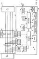
- FIG. 1 represents a demand response event compliance verification system 10.
- consumers 12 may receive power from a utility provider 14 via a power grid of alternating current (AC) power lines 16.
- the power grid 16 may supply power to any suitable number of consumers 12, here labeled 1-N.
- These consumers 12 may represent, for example, residential or commercial consumers of power or those paying utility bills for combined electric usage for end consumers (e.g., commercial building owners, condo associations, and so forth), each of which may consume power by running a number of loads 18.
- the consumers 12 may include natural persons, business entities, commercial or residential properties, equipment, and so forth.
- the loads 18 may include, for example, certain relatively high-power-consuming loads 18, such as HVAC appliances, pool pumps, cooking appliances (e.g., ovens, ranges, cooktops, microwave ovens, etc.), laundry machines (e.g., clothes washers and dryers), refrigerators and freezers, electric vehicles being charged, industrial equipment (e.g., pumps and motors) and so forth, as well as certain relatively low-power-consuming loads 18, such as televisions, computers, and lights. As shown in FIG. 1 , each consumer 12 may be running 1-N loads 18 at any given point in time.
- loads 18 such as HVAC appliances, pool pumps, cooking appliances (e.g., ovens, ranges, cooktops, microwave ovens, etc.), laundry machines (e.g., clothes washers and dryers), refrigerators and freezers, electric vehicles being charged, industrial equipment (e.g., pumps and motors) and so forth, as well as certain relatively low-power-consuming loads 18, such as televisions, computers, and lights.
- each consumer 12 may be running 1-N loads
- a local power meter 20 may track the amount of power consumed by each consumer 12.
- Each power meter 20 may include sampling circuitry 22 and a consumer interface 24, and certain communication circuitry 26 with which the power meter 20 may communicate with the utility provider 14.
- the utility provider 14 may desire to offer incentives to the consumers 12 in exchange for refraining from running certain high-power-consuming loads 18 in a "demand response event request.”
- the utility provider 14 may communicate such a request to the consumer 12 via, for example, text messaging, phone, website, email, and/or the interface 24 of the meter 20 by way of the communication circuitry 26.
- a load 18 may include a built-in demand response system, which may automatically respond to a demand response event request from a utility provider 14 by powering the load 18 off or refusing to turn the load 18 on during a demand response event.
- the sampling circuitry 22 of power meters 20 of consumers 12 that have agreed with the demand response event request may sample discrete power consumption by the consumers 12 to obtain power usage profiles 28.
- the sampling circuitry 22 may measure the instantaneous current power consumption or change in power consumption at specific intervals (e.g., every 0.1, 0.2, 0.5, 1, 2, 5, 10, 20, or 30 seconds, or every 1, 2, or 5 minutes, or other such intervals).
- the sampling circuitry 22 samples the current power consumption of the consumer 12 at an interval long enough to provide privacy, such that relatively low-power-consuming loads 18 generally are not particularly detectable according to the techniques discussed herein, but such that relatively high-power-consuming loads 18 are detectable (e.g., approximately every 5-10 seconds or longer).
- the power meters 20 may communicate these power usage profiles 28 via the communication circuitry 26.
- This communication circuitry 26 may include wireless communication circuitry capable of communicating via a network such as a personal area network (PAN) such as a Bluetooth network, a local area network (LAN) such as an 802.11x Wi-Fi network, a wide area network (WAN) such as a 3G or 4G cellular network (e.g., WiMax), and/or a power line data transmission network such as Power Line Communication (PLC) or Power Line Carrier Communication (PLCC).
- PAN personal area network
- LAN local area network
- WAN wide area network
- 3G or 4G cellular network e.g., WiMax
- PLC Power Line Communication
- PLCC Power Line Carrier Communication
- a compliance server 30 associated with the utility provider 14 may receive the power usage profiles and determine whether the consumers 12 have complied with the demand response event request. Although the compliance server 30 is illustrated as being associated with the utility provider 14, the compliance server 30 may be associated instead with a third party service, or may represent a capability of the power meter 20.
- the compliance server 30 may include a processor 32, memory 34, and storage 36.
- the processor 32 may be operably coupled to the memory 34 and/or the storage 36 to carry out the presently disclosed techniques. These techniques may be carried out by the processor 32 and/or other data processing circuitry based on certain instructions executable by the processor 32. Such instructions may be stored using any suitable article of manufacturer, which may include one or more tangible, computer-readable media to at least collectively store these instructions.
- the article of manufacturer may include, for example, the memory 34 and/or the nonvolatile storage 36.
- the memory 34 and the nonvolatile storage 36 may include any suitable articles of manufacturer for storing data and executable instructions, such a random-access memory, read-only memory, rewriteable flash memory, hard drives, and optical disks.
- the compliance server 30 may compare the power usage profiles 28 received from the power meters 20 with various load profiles, which may be stored in the storage 36 and which may represent patterns of power consumption by certain types of loads 18. If the compliance server 30 determines that a power usage profile 28 matches a load profile associated with the type of load the consumer 12 agreed not to run, the compliance server 30 may output a compliance indication 38 indicating that the consumer 12 has not complied with the demand response event request. If the compliance server 30 does not determine that the power usage profile 28 matches a load profile from the nonvolatile storage 36 that represents a type of device that has been agreed not to be run during a demand response event, the compliance server 30 may output the compliance indication 38 to indicate that the consumer 12 is in compliance with the demand response event request.
- the power meters 20 may take a variety of forms.
- a three-phase power meter 20 appears in FIG. 2 in a power meter system 50 as joined to the power grid 16, as power flows from AC lines 52 to an AC load 12 (e.g., a residential or commercial establishment owned by a consumer 12 running any suitable number of loads 18).
- the embodiment of FIG. 2 involves monitoring three-phase power
- alternative embodiments of the power meter 20 may monitor single-phase power.
- the AC lines 52 may transmit three-phase power via three phase lines 53 and a neutral line 54.
- the power meter 20 may obtain power via power supply circuitry 56 that may couple to the three phase lines 53 and the neutral line 54 for its internal power consumption.
- the power supply circuitry 56 also may charge a battery and/or super capacitor 58.
- the backup power may be fed by a non-rechargeable battery.
- Metering circuitry 60 may ascertain power consumption by monitoring the voltage and current traversing the AC lines 52 to the AC load 12.
- voltage sensing circuitry 62 may determine the voltage based on the three phase lines 53 and the neutral line 54.
- Current transformers (CTs) 64 and current sensing circuitry 66 may determine the current flowing through the three phase lines 53.
- the metering circuitry 60 may output the current power consumption values to an electronic display 68, such as a liquid crystal display (LCD), as well as to a processor 70.
- the metering circuitry 60 may sense the voltage and current inputs and send corresponding pulses to the processor 70, which calculates various data relating to the current power consumption of the consumer 12.
- the processor 70 may calculate the energy accumulation, power factor, active power, reactive power and maximum demand, etc. These various elements may collectively form the sampling circuitry 22 that determines the power usage profile 28 representing power consumption by the consumer 12.
- the processor 70 may store the demand details in memory 72 and/or nonvolatile storage 74, which may be NVRAM (EEPROM) or other suitable nonvolatile storage, such as the nonvolatile storage discussed above in relation to the compliance server 30.
- nonvolatile storage 74 which may be NVRAM (EEPROM) or other suitable nonvolatile storage, such as the nonvolatile storage discussed above in relation to the compliance server 30.
- multiple functions of the power meter 20 may be implemented in a single chip solution, in which a single chip performs both the voltage/current sensing and the calculation of demand parameters.
- the processor 70 may generate the power usage profile 28.
- Certain audio alerts may be provided by the processor 70 to audio output circuitry 76 and/or 78, which may include a digital-to-analog converter (DAC) and a built-in speaker or external powered speakers connected by the consumer 12. These audio alerts may include, for example, an indication that the utility provider 14 has sent a demand response event request, or a reminder to shut off a load
- the processor 70 may include one or more microprocessors, such as one or more "general-purpose" microprocessors, one or more application-specific processors (ASICs), or a combination of such processing components, which may control the general operation of the power meter 20.
- the processor 70 may include one or more instruction set processors (e.g., RISC), audio processors, and/or other related chipsets.
- the memory 72 and the nonvolatile storage 74 may store the current and/or certain historical power consumption values, as well as provide instructions to enable the processor 70 to generate the power usage profile 28.
- the processor 70 may be operably coupled to the memory 72 and/or the storage 74 to carry out the presently disclosed techniques. These techniques may be carried out by the processor 70 and/or other data processing circuitry based on certain instructions executable by the processor 70. Such instructions may be stored using any suitable article of manufacturer, which may include one or more tangible, computer-readable media to least collectively store these instructions.
- the article of manufacturer may include, for example, the memory 72 and/or the nonvolatile storage 74.
- the memory 72 and the nonvolatile storage 74 may include any suitable articles of manufacturer for storing data and executable instructions, such a random-access memory, read-only memory, rewriteable flash memory, hard drives, and optical disks
- the processor 70 may cause an indicator light 80 to blink or flash or may display messages on the display 68.
- a message may include a demand response event request or a reminder to comply with a demand response event request.
- the consumer 12 may respond by pressing a user pushbutton 82 or via a peripheral device 84, such as a computing device (e.g., computer or portable phone) or an input device (e.g., a keyboard or touch-sensitive screen).
- a peripheral device 84 such as a computing device (e.g., computer or portable phone) or an input device (e.g., a keyboard or touch-sensitive screen).
- These components of the power meter 20, including the display 68 and the audio output circuitry 76 and/or 78 generally may represent the interface circuitry 24 of the power meter 20.
- the communication circuitry 26 is represented as communication device(s) 86 in FIG.
- PAN personal area network
- LAN local area network
- WAN wide area network
- IR infrared
- USB Universal Serial Bus
- PLC Power Line Communication
- PLC Power Line Carrier Communication
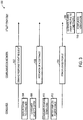
- FIG. 3 One embodiment of communication 100 that may take place between a consumer 12 and the utility provider 14 appears in FIG. 3 .
- the utility provider 14 may initially issue a demand response event request (block 102) asking the consumer 12 not to run a type of load 18 (e.g., a high-power-consuming appliance such as an HVAC or charging an electric vehicle) during a demand response event where power demand is expected to be excessively high.
- the utility provider 13 may issue the demand response event request of block 102 via any suitable network.
- the consumer 12 may receive the demand response event request of block 102 at the interface circuitry 24 of the power meter 20, or via some other communication with the consumer 12, such as via text message, phone, email, a website, etc.
- the power meter 20 may display the offer to the consumer 12 (block 104) on the display 68 of the power meter 20.
- the consumer 12 may accept the offer of the demand response event request of block 102, for example, by interacting with the interface 24 of the power meter 20 or by replying to the text message, phone, email, or website.
- an indication of acceptance (block 108) may be sent to the utility provider 14.
- the power meter 20 may transmit the indication of acceptance of block 108 via the communication device(s) 84.
- the utility provider 14 may communicate to the power meter 20 that the consumer 12 has accepted the demand response event request of block 102.
- the consumer 12 may power down the load 18 per the agreement of the demand response event request (block 110). Thereafter, at least during the demand response event, the power meter 20 may sample consumer 12 power usage to obtain a power usage profile 28 (block 112). The power meter 20 may communicate this power usage profile 28 via the communication network to the compliance server 30 associated with the utility provider 14 (block 114), which may compare the power usage profile 28 to various load profiles (block 116). Since the consumer 12 has powered down the load 18 per the demand response event request agreement, the compliance server 30 will not find a match between the load profiles representing the type of load the consumer 12 agreed not to run and the power usage profile 28, and thus compliance may be verified with a compliance indication 38 (block 118).
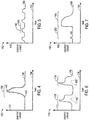
- FIGS. 4-7 represent various exemplary plots modeling load profiles, which represent patterns of power consumption typical to certain types of loads 18. It should be appreciated that the plots of FIGS. 4-7 are intended only to be representative of the general type of load profiles that may be stored in the nonvolatile storage 36 of the compliance server 30.
- the various load profiles are measured empirically and may include varying levels of detail to distinguish between broad classes of loads 18 (e.g., HVAC systems, ovens, clothes dryers, refrigerators, electric vehicles, industrial motors, and so forth) or even to distinguish between specific brands or even models of certain loads 18 (e.g., an oven by General Electric Company, an HVAC system by General Electric Company, and so forth).
- loads 18 e.g., HVAC systems, ovens, clothes dryers, refrigerators, electric vehicles, industrial motors, and so forth
- any suitable format may convey the information presented by load profiles such as those shown in FIGS. 4-7 .
- the load profiles may be represented by vector data or delta values that indicate change in power consumption over time.
- a plot 130 shown in FIG. 4 represents a load profile associated with a clothes dryer.
- An ordinate 132 represents energy usage and an abscissa 134 represents time.
- a real power consumption curve 136 illustrates the general manner in which a clothes dryer may consume power over time, increasing during an active period 138 and reaching a peak 140 before relatively rapidly returning to a baseline level of power consumption.
- reactive effects 142 caused by a clothes dryer generally may track the real power consumption curve 136.
- a plot 150 shown in FIG. 5 generally represents a load profile associated with a refrigerator.
- an ordinate 152 represents energy usage and abscissa 154 represents time.
- a real power consumption curve 156 illustrates that, during active periods 158 when the refrigerator is actively discharging heat, power consumption may be moderately higher than a baseline occurring during an inactive period 160, when the refrigerator is temporarily drawing less power.
- a plot 170 shown in FIG. 6 represents a load profile associated with an HVAC system.
- An ordinate 172 represents energy usage, while an abscissa 174 represents time.
- a real power consumption curve 176 represents power consumption of an HVAC system taking place over time. During active periods 178, the HVAC system may draw significant amounts of power, as shown in the plot 170. At these times, the certain reactive effects 180, which do not necessarily track the real power consumption curve 176, may be detectable.
- the power consumption patterns of some loads may include a power consumption code identifying the type of load.
- An embodiment of a load profile associated with such a load 18 appears in a plot 190 of FIG. 7 .
- an ordinate 192 represents energy usage
- an abscissa 194 represents time.
- a power consumption curve 196 represents real power consumption by a load 18 (e.g., an appliance) capable of self-identifying through a power consumption code.
- the load 18 is an oven capable of self-identifying through a power consumption code.
- the energy consumption of the load 18 may begin at a relatively high level of power consumption, gradually returning to a baseline level of power consumption.
- the load 18 may emit a power consumption identity code 200.
- This power consumption identity code 200 may include a series of pulses of energy consumption, which may specifically identify the load 18 as being in a specific class of appliances (e.g., that the load 18 is an oven), or even identifying the specific brand of the appliance (e.g., that the load 18 is an oven by General Electric Company).
- the power consumption identity code 200 may enable identification of the load 18 based on the number, amplitude, or spacing of pulses.
- the power consumption identity code 200 may provide an indication of an appliance type, manufacturer, model number, age, and so forth. It should be appreciated that loads 18 may be sold having such a power consumption identity code 200 programmed thereon (e.g., as machine readable instructions on a suitable article of manufacture, such as a read only memory, random access memory, flash memory, and so forth).
- the compliance server 30 may compare a power usage profile 28 measured by a power meter 20 with various load profiles, such as those represented by the plots of FIGS. 4-7 .
- the load profiles and/or the power usage profile 28 may be represented in a variety of forms. Such forms may include a series of discrete numerical data points, indications of changes from one point in time to another point in time, mathematical relationships or equations, or vector representations of the power consumption, to name only a few.
- the power usage profiles 28 and/or load profiles may take any other suitable form to enable their comparison to detect when an appliance is running for compliance verification purposes. Load profiles, such as those represented and suggested by the examples of FIGS.
- load profiles or collections of load profiles may be sold to utility providers 14 to enable the utility providers to verify when consumers 12 are in compliance with a demand response event.
- the compliance server 30 may compare the power usage profile 28 to the load profiles after performing certain processing generally isolate the components of the power usage profile due to high-power-consuming loads 18.
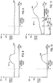
- FIGS. 8-10 illustrate one manner of removing certain baseline power consumption of the power usage profile 28 due to relatively low-power-consuming loads 18, before comparing the remaining components of the power usage profile 28, due to the high-power-consuming loads 18, to one or more load profiles.
- a power usage profile 28 shown by a plot 210 is unlikely to represent power consumption caused exclusively by a single load 18.
- a consumer 12 may be running any number of loads 18, only one of which may be a type of load 18 that the utility provider 14 has requested the consumer 12 not run during a demand response event.
- a user may be running relatively low-power-consuming loads 18, such as a television, a computer, lights, and so forth, in addition to other relatively high-power-consuming loads 18.
- a baseline level of power consumption due to these loads 18 may be present prior to the start of the demand response event.
- the plot 210 of FIG. 8 includes an ordinate 212 representing energy usage and an abscissa 214 representing time, which encompasses a period of time both before and after the start of a demand response event at a time t 0 .
- a power consumption curve 216 may include the sum of all power consumed by loads 18 run by the consumer 12. As such, the power usage profile 28 shown in the plot 210 may include a certain level of baseline noise resulting from many different relatively low-power-consuming loads 18.
- Such a baseline amount of power consumption is represented by a plot 220 of FIG. 9 .
- an ordinate 222 represents energy usage
- an abscissa 224 represents time, including a period of time before and after the start of the demand response event at time t 0 .
- a power consumption curve 226 represents the baseline amount of power consumption occurring in the power usage profile 28 represented by the plot 210 of FIG. 8 .
- the baseline power consumption curve 226 may be based on the period of time just prior to time t 0 (e.g., 10 s, 30 s, 1 min., 2 min., 5 min., 10 min., 20 min., 30 min., 1 hour, etc.) the demand response event begins, or may be determined by estimating a likely amount of baseline power consumption (e.g., through empirically measured averages of power consumption by a typical consumer 12 or the same consumer 12), or may be determined based on historical power usage by the specific consumer 12 to which the power usage profile 28 belongs, for example.
- the plot 230 may include an ordinate 232 representing energy usage and abscissa 234 representing time, which represents time before and after the start of a demand response event at time t 0 .
- a revised power consumption curve 236 represents power consumption due to relatively high-power-consuming loads 18, which may be of particular interest during a demand response event.
- This power consumption curve 236 may be compared in the compliance server 30 to one or more load profiles until a match is found that identifies the type of loads 18 that the consumer 12 is running during the demand response event. From such comparisons, the compliance server 30 may identify whether the consumer 12 is running a type of load that the consumer 12 has agreed not to run.
- the baseline power consumption of a power usage profile 28 may be determined based on typical power consumption occurring during several different periods prior to the start of a demand response event. For example, as shown by a plot 240 of FIG. 11 , which includes an ordinate 242 representing energy usage and an abscissa 244 representing time, including times before and after the start of a demand response event at time t 0 , a variety of baselines may be developed to compare to a power consumption curve 246. More than one baseline component may be subtracted from the power consumption curve 246, such as a first baseline component 248 determined as occurring between a time t 0-A and t 0 .
- This first baseline component 248 may be relatively shorter than other baseline components to be determined (e.g., the first baseline component 248 may last approximately 10 s).
- a second baseline component 250 may be determined as occurring between t 0-B to t 0 , and may last, for example, approximately two or more times as long as the first baseline component (e.g., approximately 30 seconds).
- a third baseline component 252 may be determined between t 0-C and t 0 , and may last approximately two or more times longer than the second baseline component 250 (e.g., 1 min.).
- these various baseline components 248, 250, and 252 may be averaged to produce a single average baseline component that may be subtracted from the component of the power consumption curve 246 occurring during the demand response event.
- the baseline components 248, 250, and 252 may be separately subtracted from the power consumption curve 246 to produce three distinct revised power usage profiles 28 that may be compared to the load profiles in the compliance server 30.
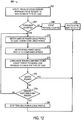
- FIG. 12 represents a flowchart 260 that describes a method for carrying out the techniques discussed above.
- the flowchart 260 may begin when the utility provider 14 issues a demand response event request to a consumer 12, asking the consumer 12 to shut down a specific type of load 18 during a demand response event (block 262). If the consumer 12 does not accept the demand response event request (decision block 264) this refusal may be detected and counted (e.g., by the power meter 20) (block 266) and a corresponding notification sent to the utility provider 14 (block 268).
- the power meter 20 may sample the current power consumption of the consumer 12 to obtain a power usage profile during at least the compliance period of the demand response event (block 270).
- the power meter 20 may send the power usage profile 28 determined in block 270 to a compliance server 30 associated with the utility provider 14 (block 272).
- the compliance server 30 may compare the power usage profile to various known application profiles stored in the nonvolatile storage 36, which may indicate the types of loads that the consumer 12 is running (block 274). If a match is found (decision block 276), the consumer 12 may be understood to be in noncompliance with the demand response event request, and a notification indicating such may be sent to the power utility 14 (block 268).
- the power meter 20 may stop tracking the power usage profile 28 of the consumer 12 (block 280), and a notification indicating that the user remained in compliance during the demand response event may be sent to the power utility 14 (block 268).
- a consumer 12 may be temporarily in noncompliance with a demand response event request.
- a consumer 12 may be running the type of load 18 the consumer 12 agreed not to run during the demand response event), and might otherwise continue to run the load 18 by accident without a reminder.
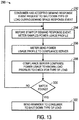
- a flowchart 290 of FIG. 13 represents an embodiment of a method for reminding a consumer 12 of current noncompliance, so that the consumer 12 may shut down the promised load 18 and may be in compliance with the demand response event request when the demand response event occurs.
- the flowchart 290 may begin after a consumer 12 has accepted a demand response event request from a utility provider 14 to shut down a specific type of load during a demand response event (block 292).
- the power meter 20 may sample the power usage profile of the consumer 12 (block 294) and send such power usage profile 28 to the compliance server 30 (block 296).
- the compliance server 30 may compare the power usage profile to the known load profiles stored in nonvolatile storage 36 associated with the compliance server 30, specifically seeking the type of load 18 that the consumer 12 has agreed not to run during the demand response event (block 298). If a match is not found (decision block 300), the actions of blocks 294-298 may continue until the start of the demand response event.
- Technical effects of the invention include enabling a manner of detecting compliance with a demand response event request, when a consumer has been requested not to run a specific type of load during periods of peak power consumption.
- a utility provider may offer incentives to consumers to refrain from running certain loads (e.g., high-power-consuming appliances) during such periods of peak power consumption, when the strain of such power consumption could result in service interruptions.
- loads e.g., high-power-consuming appliances
- a utility provider may be able to detect the types of loads a consumer has chosen to run at any given point in time according to the techniques discussed above.
Landscapes
- Engineering & Computer Science (AREA)
- Power Engineering (AREA)
- Physics & Mathematics (AREA)
- General Physics & Mathematics (AREA)
- Management, Administration, Business Operations System, And Electronic Commerce (AREA)
- Remote Monitoring And Control Of Power-Distribution Networks (AREA)
- Supply And Distribution Of Alternating Current (AREA)
Applications Claiming Priority (1)
| Application Number | Priority Date | Filing Date | Title |
|---|---|---|---|
| US12/948,704 US8825215B2 (en) | 2010-11-17 | 2010-11-17 | Power consumption compliance monitoring system and method |
Publications (2)
| Publication Number | Publication Date |
|---|---|
| EP2456043A1 EP2456043A1 (en) | 2012-05-23 |
| EP2456043B1 true EP2456043B1 (en) | 2018-08-01 |
Family
ID=45318807
Family Applications (1)
| Application Number | Title | Priority Date | Filing Date |
|---|---|---|---|
| EP11188866.5A Active EP2456043B1 (en) | 2010-11-17 | 2011-11-11 | Power consumption compliance monitoring system and method |
Country Status (4)
| Country | Link |
|---|---|
| US (1) | US8825215B2 (zh) |
| EP (1) | EP2456043B1 (zh) |
| JP (1) | JP5883619B2 (zh) |
| CN (1) | CN102565525B (zh) |
Families Citing this family (48)
| Publication number | Priority date | Publication date | Assignee | Title |
|---|---|---|---|---|
| CN101938284B (zh) * | 2009-06-30 | 2014-01-01 | 深圳富泰宏精密工业有限公司 | 通信装置及其通信方法 |
| WO2012148596A1 (en) * | 2011-04-29 | 2012-11-01 | Electric Transportation Engineering Corporation, D/B/A Ecotality North America | System for measuring electricity and method of providing and using the same |
| KR101749761B1 (ko) * | 2010-12-15 | 2017-06-22 | 한국전자통신연구원 | Ami 네트워크에서의 전력기기 관리 장치 및 방법 |
| US8543251B2 (en) * | 2010-12-20 | 2013-09-24 | International Business Machines Corporation | Centralized fine grade control of device energy consumption |
| US9218628B2 (en) * | 2011-01-24 | 2015-12-22 | Beet, Llc | Method and system for generating behavior profiles for device members of a network |
| EP2671178B1 (en) | 2011-02-04 | 2018-10-17 | Bidgely Inc. | Systems and methods for improving the accuracy of appliance level disaggregation in non-intrusive appliance load monitoring techniques |
| US20120297483A1 (en) * | 2011-05-16 | 2012-11-22 | General Electric Company | Systems, methods, and apparatus for network intrusion detection based on monitoring network traffic |
| JP5092042B1 (ja) * | 2011-06-14 | 2012-12-05 | 株式会社東芝 | 映像表示装置 |
| US20120330472A1 (en) * | 2011-06-21 | 2012-12-27 | General Electric Company | Power consumption prediction systems and methods |
| US20120330473A1 (en) * | 2011-06-24 | 2012-12-27 | Bobbie Jo Meredith | System and method for managing loads |
| MX2014010767A (es) * | 2012-03-08 | 2014-10-14 | Embertec Pty Ltd | Sistema de energia. |
| AU2013251524B2 (en) | 2012-04-25 | 2016-05-12 | Bidgely Inc. | Energy disaggregation techniques for low resolution whole-house energy consumption data |
| US9964932B2 (en) * | 2012-06-12 | 2018-05-08 | Siemens Industry, Inc. | Virtual demand auditing of devices in a building |
| CN104396111B (zh) * | 2012-06-22 | 2017-03-29 | 艾思玛太阳能技术股份公司 | 电网图构建和运行引导 |
| GB2506188B (en) * | 2012-09-25 | 2014-12-17 | Landis & Gyr Oy | Device, arrangement and method for verifying the operation of electricity meter |
| JP6350284B2 (ja) * | 2012-09-27 | 2018-07-04 | 日本電気株式会社 | 情報処理装置、電力需要体、情報処理方法、及びプログラム |
| US9807099B2 (en) | 2013-03-15 | 2017-10-31 | Google Inc. | Utility portals for managing demand-response events |
| US9810442B2 (en) | 2013-03-15 | 2017-11-07 | Google Inc. | Controlling an HVAC system in association with a demand-response event with an intelligent network-connected thermostat |
| US9595070B2 (en) | 2013-03-15 | 2017-03-14 | Google Inc. | Systems, apparatus and methods for managing demand-response programs and events |
| WO2015012851A1 (en) * | 2013-07-26 | 2015-01-29 | Empire Technology Development Llc | Control of electric power consumption |
| US9702730B2 (en) * | 2013-08-09 | 2017-07-11 | Utilidata, Inc. | Systems and methods for estimating conservation allocation with partial AMI |
| US20150057820A1 (en) * | 2013-08-21 | 2015-02-26 | Fujitsu Limited | Building energy management optimization |
| JP6106052B2 (ja) * | 2013-09-02 | 2017-03-29 | 株式会社東芝 | エネルギ管理システムおよびその方法、ならびにプログラム |
| US10783524B2 (en) * | 2013-12-13 | 2020-09-22 | Energyhub, Inc. | Resource customer identity verification |
| US9442548B1 (en) | 2014-03-18 | 2016-09-13 | Amazon Technologies, Inc. | Device charging system |
| US9496736B1 (en) * | 2014-03-18 | 2016-11-15 | Amazon Technologies, Inc. | Portable device charging system |
| KR101503644B1 (ko) | 2014-04-07 | 2015-03-17 | 한국과학기술원 | 비간섭 전력 부하 감시에 알맞도록 고차 적률 특징을 쓰는 전력 신호 인식 방법 및 그 시스템 |
| FR3019902B1 (fr) * | 2014-04-11 | 2016-05-13 | Sagemcom Energy & Telecom Sas | Procede de gestion d'operations de comptage d'energie active et d'operations de comptage d'energie reactive |
| US10454273B2 (en) | 2014-10-26 | 2019-10-22 | Green Power Labs Inc. | Forecasting net load in a distributed utility grid |
| US11070058B2 (en) | 2014-10-26 | 2021-07-20 | Green Power Labs Inc. | Forecasting net load in a distributed utility grid |
| EP3240140A4 (en) * | 2014-12-25 | 2018-05-23 | Kyocera Corporation | Server, user terminal, and program |
| EP3264554B1 (en) * | 2015-02-25 | 2019-07-24 | Kyocera Corporation | Power management device, power management system, and power management method |
| US10088185B2 (en) | 2015-03-30 | 2018-10-02 | Gridpoint, Inc. | Thermostat with integrated submetering and control |
| DE102015106456A1 (de) * | 2015-04-27 | 2016-10-27 | Rwe Deutschland Ag | Verfahren und Vorrichtung zum Übertragen von auf Messwerten basierenden Lastgängen |
| KR20170035317A (ko) * | 2015-09-21 | 2017-03-30 | 주식회사 인코어드 테크놀로지스 | 사용자 맞춤형 광고를 제공하는 시스템, 사용자 관리 서버 및 방법 |
| US10444806B2 (en) * | 2015-09-24 | 2019-10-15 | Causam Energy, Inc. | Systems and methods for aggregation and integration of distributed grid elements inputs for providing an interactive electric power grid geographic visualization |
| JP6653153B2 (ja) | 2015-10-01 | 2020-02-26 | 株式会社日立製作所 | 電力需要調整計画管理装置 |
| US10042405B2 (en) * | 2015-10-22 | 2018-08-07 | Qualcomm Incorporated | Adjusting source voltage based on stored information |
| CN105403764B (zh) * | 2015-11-04 | 2018-05-01 | 上海斐讯数据通信技术有限公司 | 移动终端的功耗测试系统及方法 |
| US9904563B2 (en) * | 2015-12-18 | 2018-02-27 | Htc Corporation | Processor management |
| US9989373B2 (en) | 2016-04-21 | 2018-06-05 | Honda Motor Co., Ltd. | Coverage based demand response signals |
| CA2975467C (en) * | 2016-08-04 | 2020-11-10 | Watershed Technologies Inc. | System and method for building climate control |
| TWI662423B (zh) * | 2017-02-06 | 2019-06-11 | 台灣電力股份有限公司 | 風力發電之預測顯示系統及方法 |
| FR3069721B1 (fr) * | 2017-07-31 | 2019-08-02 | Voltalis | Lissage d'une courbe de charge comprenant une agregation de courbes de charges elementaires |
| CA3115353C (fr) | 2018-10-11 | 2022-03-15 | Hydro-Quebec | Methode, systeme et produit logiciel permettant d'identifier des installations susceptibles de presenter une non-conformite electrique |
| US11508020B2 (en) | 2019-07-09 | 2022-11-22 | Energybox Ltd. | Method for operating a power consumption metering system and power consumption metering system |
| US11125790B2 (en) * | 2019-07-09 | 2021-09-21 | Energybox Ltd. | Method for operating a power consumption metering system and power consumption metering system |
| CN114301057A (zh) * | 2021-11-23 | 2022-04-08 | 广西艾科普物联技术有限公司 | 一种通过负载情况区分用电设备的方法及系统 |
Family Cites Families (64)
| Publication number | Priority date | Publication date | Assignee | Title |
|---|---|---|---|---|
| US4347575A (en) * | 1979-07-02 | 1982-08-31 | Sangamo Weston, Inc. | System for controlling power distribution to customer loads |
| US4858141A (en) | 1986-04-14 | 1989-08-15 | Massachusetts Institute Of Technology | Non-intrusive appliance monitor apparatus |
| US8078431B2 (en) * | 1992-11-17 | 2011-12-13 | Health Hero Network, Inc. | Home power management system |
| US5483153A (en) * | 1994-03-24 | 1996-01-09 | Massachusetts Institute Of Technology | Transient event detector for use in nonintrusive load monitoring systems |
| US5717325A (en) * | 1994-03-24 | 1998-02-10 | Massachusetts Institute Of Technology | Multiprocessing transient event detector for use in a nonintrusive electrical load monitoring system |
| US5572438A (en) * | 1995-01-05 | 1996-11-05 | Teco Energy Management Services | Engery management and building automation system |
| US5924486A (en) * | 1997-10-29 | 1999-07-20 | Tecom, Inc. | Environmental condition control and energy management system and method |
| US6891478B2 (en) * | 2000-06-09 | 2005-05-10 | Jay Warren Gardner | Methods and apparatus for controlling electric appliances during reduced power conditions |
| US6519509B1 (en) * | 2000-06-22 | 2003-02-11 | Stonewater Software, Inc. | System and method for monitoring and controlling energy distribution |
| US6906617B1 (en) * | 2000-11-17 | 2005-06-14 | Koninklijke Philips Electronics N.V. | Intelligent appliance home network |
| US20030036810A1 (en) * | 2001-08-15 | 2003-02-20 | Petite Thomas D. | System and method for controlling generation over an integrated wireless network |
| KR100701110B1 (ko) * | 2002-03-28 | 2007-03-30 | 로버트쇼 컨트롤즈 캄파니 | 에너지 관리 시스템 및 방법 |
| JP3892358B2 (ja) * | 2002-07-23 | 2007-03-14 | 財団法人電力中央研究所 | 消費電力の変動が頻繁に起こる電気機器の動作状態を推定する方法および消費電力の変動が頻繁に起こる電気機器のモニタリングシステム |
| US7877235B2 (en) * | 2003-01-31 | 2011-01-25 | Verisae, Inc. | Method and system for tracking and managing various operating parameters of enterprise assets |
| WO2004070507A2 (en) | 2003-02-07 | 2004-08-19 | Power Measurement Ltd. | A method and system for calculating and distributing utility costs |
| US7010363B2 (en) | 2003-06-13 | 2006-03-07 | Battelle Memorial Institute | Electrical appliance energy consumption control methods and electrical energy consumption systems |
| US6860431B2 (en) * | 2003-07-10 | 2005-03-01 | Tumkur S. Jayadev | Strategic-response control system for regulating air conditioners for economic operation |
| US20070043478A1 (en) * | 2003-07-28 | 2007-02-22 | Ehlers Gregory A | System and method of controlling an HVAC system |
| US7373222B1 (en) * | 2003-09-29 | 2008-05-13 | Rockwell Automation Technologies, Inc. | Decentralized energy demand management |
| US7379791B2 (en) * | 2004-08-03 | 2008-05-27 | Uscl Corporation | Integrated metrology systems and information and control apparatus for interaction with integrated metrology systems |
| EP1705617A3 (fr) * | 2005-03-24 | 2011-04-20 | France Telecom | Procédé et dispositif de suivi à distance de l'activité d'une personne dans une habitation |
| US20070018852A1 (en) * | 2005-07-19 | 2007-01-25 | Seitz Shane M | Power load pattern monitoring system |
| WO2007014146A2 (en) | 2005-07-22 | 2007-02-01 | Cannon Technologies, Inc. | Load shedding control for cycled or variable load appliances |
| US7885917B2 (en) * | 2006-05-26 | 2011-02-08 | Board Of Regents Of The Nevada System Of Higher Education, On Behalf Of The Desert Research Institute | Utility monitoring and disaggregation systems and methods of use |
| US7580775B2 (en) * | 2006-07-11 | 2009-08-25 | Regen Energy Inc. | Method and apparatus for implementing enablement state decision for energy consuming load based on demand and duty cycle of load |
| WO2008039759A2 (en) * | 2006-09-25 | 2008-04-03 | Intelligent Management Systems Corporation | System and method for resource management |
| US7747357B2 (en) * | 2006-11-13 | 2010-06-29 | Lutron Electronics Co., Inc. | Method of communicating a command for load shedding of a load control system |
| US7705484B2 (en) * | 2007-04-10 | 2010-04-27 | Whirlpool Corporation | Energy management system and method |
| US20090063257A1 (en) * | 2007-08-31 | 2009-03-05 | Powerit Solutions, Llc | Automated peak demand controller |
| US8094034B2 (en) * | 2007-09-18 | 2012-01-10 | Georgia Tech Research Corporation | Detecting actuation of electrical devices using electrical noise over a power line |
| US8160752B2 (en) | 2008-09-30 | 2012-04-17 | Zome Networks, Inc. | Managing energy usage |
| EP2227700A2 (en) * | 2007-12-26 | 2010-09-15 | Greenlet Technologies Ltd. | Reducing power consumption in a network by detecting electrical signatures of appliances |
| US20090187499A1 (en) * | 2008-01-21 | 2009-07-23 | David Mulder | System, Method and Computer Program Product for Providing Demand Response Functionality |
| KR100960503B1 (ko) | 2008-02-05 | 2010-06-01 | 엘에스산전 주식회사 | 에너지 수요관리가 가능한 지능형 전자식 미터 및 이를이용한 수요관리 방법 |
| GB0803140D0 (en) * | 2008-02-21 | 2008-03-26 | Sentec Ltd | Technique for inference of multiple appliances' power use from single point measurements |
| US8326551B2 (en) * | 2008-04-22 | 2012-12-04 | Xerox Corporation | Method and system for incorporating electronic signature analysis in low voltage power supplies |
| US8260468B2 (en) | 2008-06-25 | 2012-09-04 | Versify Solutions, Inc. | Aggregator, monitor, and manager of distributed demand response |
| NZ590303A (en) * | 2008-07-07 | 2013-01-25 | Control4 Corp | Method and system for saving power for electronic equipment wherein the user can alter the opportunities |
| WO2010007369A2 (en) | 2008-07-17 | 2010-01-21 | Isis Innovation Limited | Utility metering |
| US8463452B2 (en) * | 2008-07-29 | 2013-06-11 | Enmetric Systems, Inc. | Apparatus using time-based electrical characteristics to identify an electrical appliance |
| US8843242B2 (en) * | 2008-09-15 | 2014-09-23 | General Electric Company | System and method for minimizing consumer impact during demand responses |
| US8433452B2 (en) | 2008-09-15 | 2013-04-30 | Aclara Power-Line Systems, Inc. | Method for load control using temporal measurements of energy for individual pieces of equipment |
| US8541719B2 (en) * | 2008-09-15 | 2013-09-24 | General Electric Company | System for reduced peak power consumption by a cooking appliance |
| CA2723083A1 (en) * | 2008-09-15 | 2010-03-18 | General Electric Company | Energy management of clothes dryer appliance |
| US20100070214A1 (en) * | 2008-09-18 | 2010-03-18 | Searete Llc, A Limited Liability Corporation Of The State Of Delaware | System and method for identifying appliances by electrical characteristics |
| US20100070218A1 (en) * | 2008-09-18 | 2010-03-18 | Searete Llc, A Limited Liability Corporation Of The State Of Delaware | System and method for identifying appliances by electrical characteristics |
| US8412654B2 (en) * | 2008-10-08 | 2013-04-02 | Rey Montalvo | Method and system for fully automated energy curtailment |
| KR101022574B1 (ko) * | 2008-10-28 | 2011-03-16 | 한국전력공사 | 고객기준부하 기반의 상시 부하 저감 시스템 |
| CA2743667A1 (en) * | 2008-11-14 | 2010-05-20 | Thinkeco Power Inc. | System and method of democratizing power to create a meta-exchange |
| US8090480B2 (en) * | 2009-01-07 | 2012-01-03 | International Business Machines Corporation | Consumer electronic usage monitoring and management |
| US8271147B2 (en) * | 2009-02-26 | 2012-09-18 | Massachusetts Institute Of Technology | Methods and apparatus for energy demand management |
| US8156055B2 (en) * | 2009-05-04 | 2012-04-10 | ThinkEco, Inc. | System and method for utility usage, monitoring and management |
| US8406933B2 (en) * | 2009-08-18 | 2013-03-26 | Control4 Corporation | Systems and methods for estimating the effects of a request to change power usage |
| EP2290328B1 (en) * | 2009-08-24 | 2015-03-04 | Accenture Global Services Limited | Utility management system |
| US8744638B2 (en) * | 2009-09-11 | 2014-06-03 | General Electric Company | Method and system for demand response in a distribution network |
| US8138626B2 (en) * | 2009-10-25 | 2012-03-20 | Greenwave Reality, Pte Ltd. | Power node for energy management |
| US20110106327A1 (en) * | 2009-11-05 | 2011-05-05 | General Electric Company | Energy optimization method |
| US20110112780A1 (en) * | 2009-11-06 | 2011-05-12 | David Moss | Electrical power consumption measuring system |
| US8063787B2 (en) * | 2009-12-16 | 2011-11-22 | Parker Kevin L | Point-of-use status indicator |
| US20110153100A1 (en) * | 2009-12-22 | 2011-06-23 | General Electric Company | Demand response appliance power consumption feedback |
| US20110153101A1 (en) * | 2009-12-22 | 2011-06-23 | General Electric Company | Household energy management system and method for one or more appliances |
| US9299093B2 (en) * | 2010-01-29 | 2016-03-29 | GM Global Technology Operations LLC | Method for charging a plug-in electric vehicle |
| JP5876874B2 (ja) * | 2010-06-04 | 2016-03-02 | センサス ユーエスエー インク.Sensus Usa Inc. | 非侵入型負荷監視及び処理方法並びにシステム |
| US20120078547A1 (en) * | 2010-09-27 | 2012-03-29 | Lutron Electronics Co., Inc. | Internet based energy control system |
-
2010
- 2010-11-17 US US12/948,704 patent/US8825215B2/en active Active
-
2011
- 2011-11-11 EP EP11188866.5A patent/EP2456043B1/en active Active
- 2011-11-14 JP JP2011248259A patent/JP5883619B2/ja not_active Expired - Fee Related
- 2011-11-17 CN CN201110385873.5A patent/CN102565525B/zh not_active Expired - Fee Related
Also Published As
| Publication number | Publication date |
|---|---|
| CN102565525B (zh) | 2016-06-01 |
| JP2012110218A (ja) | 2012-06-07 |
| US20120123995A1 (en) | 2012-05-17 |
| JP5883619B2 (ja) | 2016-03-15 |
| CN102565525A (zh) | 2012-07-11 |
| EP2456043A1 (en) | 2012-05-23 |
| US8825215B2 (en) | 2014-09-02 |
Similar Documents
| Publication | Publication Date | Title |
|---|---|---|
| EP2456043B1 (en) | Power consumption compliance monitoring system and method | |
| JP5644774B2 (ja) | 電力計測システム、電力計測方法および情報処理装置 | |
| EP2535997A2 (en) | Systems, methods, and apparatus for evaluating load power consumption utilizing a power meter | |
| US20150268281A1 (en) | System and method for monitoring, analyzing and acting upon electricity patterns | |
| US11435772B2 (en) | Systems and methods for optimizing energy usage using energy disaggregation data and time of use information | |
| US20130073105A1 (en) | System and methods for renewable power notifications | |
| US20130046414A1 (en) | Method and system of demand control based on power factor | |
| US9748771B2 (en) | Plug arrangements for alleviating peak loads | |
| JP6264695B2 (ja) | 電力管理装置、及び情報提示方法 | |
| JP6386064B2 (ja) | 電力管理装置、電力管理方法及び電力管理システム | |
| EP3743978A1 (en) | Method and apparatus for charging a battery with ac power based on state of battery related information | |
| JP2012196127A (ja) | 電気デバイスのエネルギー使用量プロファイルを生成するシステムおよび方法 | |
| JP2010226804A (ja) | 電力管理システム、電力管理方法及び検出器 | |
| WO2017033282A1 (ja) | 制御装置、イベント情報表示方法及びプログラム | |
| AU2013100843A4 (en) | Monitoring Energy Use | |
| US20130073483A1 (en) | Systems, Methods, and Apparatus for Protecting Power Transformers | |
| BR102012021752A2 (pt) | Método e sistema | |
| JPWO2017109957A1 (ja) | 電力管理装置、サーバ、電力管理システム、電力管理方法、及び、プログラム | |
| JP6376379B2 (ja) | 電力管理装置 | |
| JP6261755B2 (ja) | 制御装置、機器制御方法及びプログラム | |
| JP2013033043A (ja) | 計量に使用されるタイマベースのバッファの方法およびシステム | |
| AU2013237683B2 (en) | Utility based backup management | |
| Odusami et al. | An improved SMS based metering system | |
| TW201933724A (zh) | 用電量管理系統 | |
| PH12015000340A1 (en) | A system for and method of providing energy consumption related information based on monitored energy data |
Legal Events
| Date | Code | Title | Description |
|---|---|---|---|
| PUAI | Public reference made under article 153(3) epc to a published international application that has entered the european phase |
Free format text: ORIGINAL CODE: 0009012 |
|
| AK | Designated contracting states |
Kind code of ref document: A1 Designated state(s): AL AT BE BG CH CY CZ DE DK EE ES FI FR GB GR HR HU IE IS IT LI LT LU LV MC MK MT NL NO PL PT RO RS SE SI SK SM TR |
|
| AX | Request for extension of the european patent |
Extension state: BA ME |
|
| 17P | Request for examination filed |
Effective date: 20121123 |
|
| RIC1 | Information provided on ipc code assigned before grant |
Ipc: G01R 21/133 20060101ALI20180404BHEP Ipc: H02J 13/00 20060101AFI20180404BHEP Ipc: H02J 3/14 20060101ALI20180404BHEP |
|
| GRAP | Despatch of communication of intention to grant a patent |
Free format text: ORIGINAL CODE: EPIDOSNIGR1 |
|
| STAA | Information on the status of an ep patent application or granted ep patent |
Free format text: STATUS: GRANT OF PATENT IS INTENDED |
|
| INTG | Intention to grant announced |
Effective date: 20180517 |
|
| GRAS | Grant fee paid |
Free format text: ORIGINAL CODE: EPIDOSNIGR3 |
|
| GRAA | (expected) grant |
Free format text: ORIGINAL CODE: 0009210 |
|
| STAA | Information on the status of an ep patent application or granted ep patent |
Free format text: STATUS: THE PATENT HAS BEEN GRANTED |
|
| AK | Designated contracting states |
Kind code of ref document: B1 Designated state(s): AL AT BE BG CH CY CZ DE DK EE ES FI FR GB GR HR HU IE IS IT LI LT LU LV MC MK MT NL NO PL PT RO RS SE SI SK SM TR |
|
| REG | Reference to a national code |
Ref country code: GB Ref legal event code: FG4D |
|
| REG | Reference to a national code |
Ref country code: CH Ref legal event code: EP Ref country code: AT Ref legal event code: REF Ref document number: 1025479 Country of ref document: AT Kind code of ref document: T Effective date: 20180815 |
|
| REG | Reference to a national code |
Ref country code: IE Ref legal event code: FG4D |
|
| REG | Reference to a national code |
Ref country code: DE Ref legal event code: R096 Ref document number: 602011050518 Country of ref document: DE |
|
| REG | Reference to a national code |
Ref country code: FR Ref legal event code: PLFP Year of fee payment: 8 |
|
| REG | Reference to a national code |
Ref country code: SE Ref legal event code: TRGR |
|
| REG | Reference to a national code |
Ref country code: NL Ref legal event code: MP Effective date: 20180801 |
|
| REG | Reference to a national code |
Ref country code: LT Ref legal event code: MG4D |
|
| REG | Reference to a national code |
Ref country code: AT Ref legal event code: MK05 Ref document number: 1025479 Country of ref document: AT Kind code of ref document: T Effective date: 20180801 |
|
| PG25 | Lapsed in a contracting state [announced via postgrant information from national office to epo] |
Ref country code: FI Free format text: LAPSE BECAUSE OF FAILURE TO SUBMIT A TRANSLATION OF THE DESCRIPTION OR TO PAY THE FEE WITHIN THE PRESCRIBED TIME-LIMIT Effective date: 20180801 Ref country code: NO Free format text: LAPSE BECAUSE OF FAILURE TO SUBMIT A TRANSLATION OF THE DESCRIPTION OR TO PAY THE FEE WITHIN THE PRESCRIBED TIME-LIMIT Effective date: 20181101 Ref country code: GR Free format text: LAPSE BECAUSE OF FAILURE TO SUBMIT A TRANSLATION OF THE DESCRIPTION OR TO PAY THE FEE WITHIN THE PRESCRIBED TIME-LIMIT Effective date: 20181102 Ref country code: RS Free format text: LAPSE BECAUSE OF FAILURE TO SUBMIT A TRANSLATION OF THE DESCRIPTION OR TO PAY THE FEE WITHIN THE PRESCRIBED TIME-LIMIT Effective date: 20180801 Ref country code: IS Free format text: LAPSE BECAUSE OF FAILURE TO SUBMIT A TRANSLATION OF THE DESCRIPTION OR TO PAY THE FEE WITHIN THE PRESCRIBED TIME-LIMIT Effective date: 20181201 Ref country code: LT Free format text: LAPSE BECAUSE OF FAILURE TO SUBMIT A TRANSLATION OF THE DESCRIPTION OR TO PAY THE FEE WITHIN THE PRESCRIBED TIME-LIMIT Effective date: 20180801 Ref country code: PL Free format text: LAPSE BECAUSE OF FAILURE TO SUBMIT A TRANSLATION OF THE DESCRIPTION OR TO PAY THE FEE WITHIN THE PRESCRIBED TIME-LIMIT Effective date: 20180801 Ref country code: NL Free format text: LAPSE BECAUSE OF FAILURE TO SUBMIT A TRANSLATION OF THE DESCRIPTION OR TO PAY THE FEE WITHIN THE PRESCRIBED TIME-LIMIT Effective date: 20180801 Ref country code: AT Free format text: LAPSE BECAUSE OF FAILURE TO SUBMIT A TRANSLATION OF THE DESCRIPTION OR TO PAY THE FEE WITHIN THE PRESCRIBED TIME-LIMIT Effective date: 20180801 Ref country code: BG Free format text: LAPSE BECAUSE OF FAILURE TO SUBMIT A TRANSLATION OF THE DESCRIPTION OR TO PAY THE FEE WITHIN THE PRESCRIBED TIME-LIMIT Effective date: 20181101 |
|
| PG25 | Lapsed in a contracting state [announced via postgrant information from national office to epo] |
Ref country code: LV Free format text: LAPSE BECAUSE OF FAILURE TO SUBMIT A TRANSLATION OF THE DESCRIPTION OR TO PAY THE FEE WITHIN THE PRESCRIBED TIME-LIMIT Effective date: 20180801 Ref country code: AL Free format text: LAPSE BECAUSE OF FAILURE TO SUBMIT A TRANSLATION OF THE DESCRIPTION OR TO PAY THE FEE WITHIN THE PRESCRIBED TIME-LIMIT Effective date: 20180801 Ref country code: HR Free format text: LAPSE BECAUSE OF FAILURE TO SUBMIT A TRANSLATION OF THE DESCRIPTION OR TO PAY THE FEE WITHIN THE PRESCRIBED TIME-LIMIT Effective date: 20180801 Ref country code: ES Free format text: LAPSE BECAUSE OF FAILURE TO SUBMIT A TRANSLATION OF THE DESCRIPTION OR TO PAY THE FEE WITHIN THE PRESCRIBED TIME-LIMIT Effective date: 20180801 |
|
| PG25 | Lapsed in a contracting state [announced via postgrant information from national office to epo] |
Ref country code: CZ Free format text: LAPSE BECAUSE OF FAILURE TO SUBMIT A TRANSLATION OF THE DESCRIPTION OR TO PAY THE FEE WITHIN THE PRESCRIBED TIME-LIMIT Effective date: 20180801 Ref country code: RO Free format text: LAPSE BECAUSE OF FAILURE TO SUBMIT A TRANSLATION OF THE DESCRIPTION OR TO PAY THE FEE WITHIN THE PRESCRIBED TIME-LIMIT Effective date: 20180801 Ref country code: EE Free format text: LAPSE BECAUSE OF FAILURE TO SUBMIT A TRANSLATION OF THE DESCRIPTION OR TO PAY THE FEE WITHIN THE PRESCRIBED TIME-LIMIT Effective date: 20180801 Ref country code: IT Free format text: LAPSE BECAUSE OF FAILURE TO SUBMIT A TRANSLATION OF THE DESCRIPTION OR TO PAY THE FEE WITHIN THE PRESCRIBED TIME-LIMIT Effective date: 20180801 |
|
| REG | Reference to a national code |
Ref country code: DE Ref legal event code: R097 Ref document number: 602011050518 Country of ref document: DE |
|
| PG25 | Lapsed in a contracting state [announced via postgrant information from national office to epo] |
Ref country code: SM Free format text: LAPSE BECAUSE OF FAILURE TO SUBMIT A TRANSLATION OF THE DESCRIPTION OR TO PAY THE FEE WITHIN THE PRESCRIBED TIME-LIMIT Effective date: 20180801 Ref country code: SK Free format text: LAPSE BECAUSE OF FAILURE TO SUBMIT A TRANSLATION OF THE DESCRIPTION OR TO PAY THE FEE WITHIN THE PRESCRIBED TIME-LIMIT Effective date: 20180801 Ref country code: DK Free format text: LAPSE BECAUSE OF FAILURE TO SUBMIT A TRANSLATION OF THE DESCRIPTION OR TO PAY THE FEE WITHIN THE PRESCRIBED TIME-LIMIT Effective date: 20180801 |
|
| PLBE | No opposition filed within time limit |
Free format text: ORIGINAL CODE: 0009261 |
|
| STAA | Information on the status of an ep patent application or granted ep patent |
Free format text: STATUS: NO OPPOSITION FILED WITHIN TIME LIMIT |
|
| REG | Reference to a national code |
Ref country code: CH Ref legal event code: PL |
|
| 26N | No opposition filed |
Effective date: 20190503 |
|
| PG25 | Lapsed in a contracting state [announced via postgrant information from national office to epo] |
Ref country code: LU Free format text: LAPSE BECAUSE OF NON-PAYMENT OF DUE FEES Effective date: 20181111 Ref country code: MC Free format text: LAPSE BECAUSE OF FAILURE TO SUBMIT A TRANSLATION OF THE DESCRIPTION OR TO PAY THE FEE WITHIN THE PRESCRIBED TIME-LIMIT Effective date: 20180801 |
|
| REG | Reference to a national code |
Ref country code: BE Ref legal event code: MM Effective date: 20181130 |
|
| REG | Reference to a national code |
Ref country code: IE Ref legal event code: MM4A |
|
| PG25 | Lapsed in a contracting state [announced via postgrant information from national office to epo] |
Ref country code: SI Free format text: LAPSE BECAUSE OF FAILURE TO SUBMIT A TRANSLATION OF THE DESCRIPTION OR TO PAY THE FEE WITHIN THE PRESCRIBED TIME-LIMIT Effective date: 20180801 Ref country code: LI Free format text: LAPSE BECAUSE OF NON-PAYMENT OF DUE FEES Effective date: 20181130 Ref country code: CH Free format text: LAPSE BECAUSE OF NON-PAYMENT OF DUE FEES Effective date: 20181130 |
|
| PG25 | Lapsed in a contracting state [announced via postgrant information from national office to epo] |
Ref country code: IE Free format text: LAPSE BECAUSE OF NON-PAYMENT OF DUE FEES Effective date: 20181111 |
|
| PG25 | Lapsed in a contracting state [announced via postgrant information from national office to epo] |
Ref country code: BE Free format text: LAPSE BECAUSE OF NON-PAYMENT OF DUE FEES Effective date: 20181130 |
|
| PG25 | Lapsed in a contracting state [announced via postgrant information from national office to epo] |
Ref country code: MT Free format text: LAPSE BECAUSE OF NON-PAYMENT OF DUE FEES Effective date: 20181111 |
|
| PG25 | Lapsed in a contracting state [announced via postgrant information from national office to epo] |
Ref country code: TR Free format text: LAPSE BECAUSE OF FAILURE TO SUBMIT A TRANSLATION OF THE DESCRIPTION OR TO PAY THE FEE WITHIN THE PRESCRIBED TIME-LIMIT Effective date: 20180801 |
|
| PG25 | Lapsed in a contracting state [announced via postgrant information from national office to epo] |
Ref country code: PT Free format text: LAPSE BECAUSE OF FAILURE TO SUBMIT A TRANSLATION OF THE DESCRIPTION OR TO PAY THE FEE WITHIN THE PRESCRIBED TIME-LIMIT Effective date: 20180801 |
|
| PG25 | Lapsed in a contracting state [announced via postgrant information from national office to epo] |
Ref country code: MK Free format text: LAPSE BECAUSE OF NON-PAYMENT OF DUE FEES Effective date: 20180801 Ref country code: CY Free format text: LAPSE BECAUSE OF FAILURE TO SUBMIT A TRANSLATION OF THE DESCRIPTION OR TO PAY THE FEE WITHIN THE PRESCRIBED TIME-LIMIT Effective date: 20180801 Ref country code: HU Free format text: LAPSE BECAUSE OF FAILURE TO SUBMIT A TRANSLATION OF THE DESCRIPTION OR TO PAY THE FEE WITHIN THE PRESCRIBED TIME-LIMIT; INVALID AB INITIO Effective date: 20111111 |
|
| REG | Reference to a national code |
Ref country code: DE Ref legal event code: R081 Ref document number: 602011050518 Country of ref document: DE Owner name: GE DIGITAL HOLDINGS LLC, SAN RAMON, US Free format text: FORMER OWNER: GENERAL ELECTRIC COMPANY, SCHENECTADY, NY, US |
|
| PGFP | Annual fee paid to national office [announced via postgrant information from national office to epo] |
Ref country code: GB Payment date: 20231019 Year of fee payment: 13 |
|
| PGFP | Annual fee paid to national office [announced via postgrant information from national office to epo] |
Ref country code: SE Payment date: 20231020 Year of fee payment: 13 Ref country code: FR Payment date: 20231020 Year of fee payment: 13 Ref country code: DE Payment date: 20231019 Year of fee payment: 13 |
|
| REG | Reference to a national code |
Ref country code: GB Ref legal event code: 732E Free format text: REGISTERED BETWEEN 20240111 AND 20240117 |