EP2455778B1 - Schätzverfahren der Winkelposition eines Ziels durch Radarerfassung, und Radar, bei dem dieses Verfahren umgesetzt wird - Google Patents
Schätzverfahren der Winkelposition eines Ziels durch Radarerfassung, und Radar, bei dem dieses Verfahren umgesetzt wird Download PDFInfo
- Publication number
- EP2455778B1 EP2455778B1 EP11188335.1A EP11188335A EP2455778B1 EP 2455778 B1 EP2455778 B1 EP 2455778B1 EP 11188335 A EP11188335 A EP 11188335A EP 2455778 B1 EP2455778 B1 EP 2455778B1
- Authority
- EP
- European Patent Office
- Prior art keywords
- target
- radar
- pulses
- angular position
- antenna
- Prior art date
- Legal status (The legal status is an assumption and is not a legal conclusion. Google has not performed a legal analysis and makes no representation as to the accuracy of the status listed.)
- Active
Links
- 238000000034 method Methods 0.000 title claims description 42
- 238000001514 detection method Methods 0.000 title description 8
- 238000005259 measurement Methods 0.000 claims description 28
- 238000002592 echocardiography Methods 0.000 claims description 13
- 238000012544 monitoring process Methods 0.000 claims 1
- 238000010586 diagram Methods 0.000 description 12
- 238000004458 analytical method Methods 0.000 description 7
- 238000012545 processing Methods 0.000 description 4
- 238000006073 displacement reaction Methods 0.000 description 3
- 238000000605 extraction Methods 0.000 description 3
- 230000001427 coherent effect Effects 0.000 description 2
- 238000001228 spectrum Methods 0.000 description 2
- 238000011282 treatment Methods 0.000 description 2
- 230000005540 biological transmission Effects 0.000 description 1
- 238000004364 calculation method Methods 0.000 description 1
- 238000012937 correction Methods 0.000 description 1
- 238000011161 development Methods 0.000 description 1
- 238000005457 optimization Methods 0.000 description 1
- 238000011084 recovery Methods 0.000 description 1
- 230000000717 retained effect Effects 0.000 description 1
- 238000005070 sampling Methods 0.000 description 1
- 238000012163 sequencing technique Methods 0.000 description 1
Images


Classifications
-
- G—PHYSICS
- G01—MEASURING; TESTING
- G01S—RADIO DIRECTION-FINDING; RADIO NAVIGATION; DETERMINING DISTANCE OR VELOCITY BY USE OF RADIO WAVES; LOCATING OR PRESENCE-DETECTING BY USE OF THE REFLECTION OR RERADIATION OF RADIO WAVES; ANALOGOUS ARRANGEMENTS USING OTHER WAVES
- G01S13/00—Systems using the reflection or reradiation of radio waves, e.g. radar systems; Analogous systems using reflection or reradiation of waves whose nature or wavelength is irrelevant or unspecified
- G01S13/02—Systems using reflection of radio waves, e.g. primary radar systems; Analogous systems
- G01S13/50—Systems of measurement based on relative movement of target
- G01S13/52—Discriminating between fixed and moving objects or between objects moving at different speeds
- G01S13/522—Discriminating between fixed and moving objects or between objects moving at different speeds using transmissions of interrupted pulse modulated waves
- G01S13/524—Discriminating between fixed and moving objects or between objects moving at different speeds using transmissions of interrupted pulse modulated waves based upon the phase or frequency shift resulting from movement of objects, with reference to the transmitted signals, e.g. coherent MTi
- G01S13/53—Discriminating between fixed and moving objects or between objects moving at different speeds using transmissions of interrupted pulse modulated waves based upon the phase or frequency shift resulting from movement of objects, with reference to the transmitted signals, e.g. coherent MTi performing filtering on a single spectral line and associated with one or more range gates with a phase detector or a frequency mixer to extract the Doppler information, e.g. pulse Doppler radar
-
- G—PHYSICS
- G01—MEASURING; TESTING
- G01S—RADIO DIRECTION-FINDING; RADIO NAVIGATION; DETERMINING DISTANCE OR VELOCITY BY USE OF RADIO WAVES; LOCATING OR PRESENCE-DETECTING BY USE OF THE REFLECTION OR RERADIATION OF RADIO WAVES; ANALOGOUS ARRANGEMENTS USING OTHER WAVES
- G01S13/00—Systems using the reflection or reradiation of radio waves, e.g. radar systems; Analogous systems using reflection or reradiation of waves whose nature or wavelength is irrelevant or unspecified
- G01S13/02—Systems using reflection of radio waves, e.g. primary radar systems; Analogous systems
- G01S13/50—Systems of measurement based on relative movement of target
- G01S13/58—Velocity or trajectory determination systems; Sense-of-movement determination systems
- G01S13/64—Velocity measuring systems using range gates
Definitions
- the present invention relates to the field of radar and in particular mobile target surveillance radars themselves embedded in a mobile carrier.
- the invention is advantageously applicable to airborne maritime surveillance radars.
- An objective of a surveillance radar is the detection and the location of a mobile target or not.
- the determination of the position of a target is done in particular by estimating its angular position which is defined by the angle between a reference axis and the axis connecting the radar, or its carrier, to the target. For example, when the reference axis points to geographic north, the angular position of the target is defined by the azimuth angle. When the reference axis is the axis of the carrier, the angular position of the target is defined by the bearing angle.
- the general principle of a surveillance radar is to emit a series of pulses through a rotating antenna that sweeps the angular space to detect the presence of a potential target. If a target is actually present in the beam of the antenna, the signal pulses are reflected on this target and return echoes to the radar which has suitable receiving means. Means for processing and analyzing the received echoes are used for the purpose of deriving information on the location of the target, in particular its angular position, its distance from the radar or its speed.
- Three methods of analyzing the received signal are known, in particular, for determining the angular position of a target using a radar.
- a first known method uses a single-channel radar that performs an analysis of the amplitude (or power) of the signal received during the scanning of the antenna.
- the amplitude of the signal received by the radar varies in function of the azimuth of the antenna following the pattern of the antenna pattern.
- the azimuth of the detected target is obtained by searching for the maximum of the amplitude. This principle is illustrated in figure 1 .
- Another known method is to perform an analysis of the signals received in the frequency domain.
- This type of method is implemented by single-channel radars known as "Doppler mode".
- Doppler mode the radar emits a series of pulses at different successive times.
- the echoes received after reflection on the target are grouped in blocks, a block comprising several pulses.
- the azimuth or bearing of the antenna is known to the radar, and a mean azimuth for a block of pulses is then defined.
- frequency domain analysis of the pulses of a block in particular by means of a Fourier transform applied to this block, it is possible to detect the presence of the target by the level of the amplitude of the echoes received by the radar.
- Each block is associated with a mean azimuth of the pointing direction of the antenna.
- the angular location of the target then consists in assigning, as estimated from the azimuth of the target, the average azimuth of the block for which a target is detected.
- the target can be detected on several consecutive blocks, a direction finding method can then be used to average the azimuth blocks by weighting them by the amplitude of the received signal.
- This type of method has the disadvantage of limiting the azimuthal detection resolution to the angular resolution separating the average azimuth from two blocks and thus indirectly to the size of a block.
- This disadvantage impacts the performance of the detection on the accuracy of the estimate of the angular position of the target. It is possible to overcome this disadvantage by performing an azimuthal overlap between two or more blocks consecutive, but the higher the recovery rate, the higher the calculation complexity is increased which impacts the cost of implementation.
- a third known method consists in using a radar comprising at least two reception channels. These two paths are commonly designated by the terms sum and delta path, and the azimuth of the target is obtained by calculating the deviation measurement, for example taken equal to the dot product of the signals from each of the two channels. The value of the deviation allows to deduce the difference between the angular position of the antenna and the actual position of the target.
- This third method has the advantage of considerably increasing the angular location accuracy with respect to the aforementioned second method, however it requires the use of a two-way reception radar, a factor for increasing the cost of equipment.
- the invention aims to remedy the aforementioned limitations of the known methods by proposing a method for determining the angular position of a target which substantially improves the accuracy and in particular the variance of the estimates made.
- the invention requires the use of a reception channel and also makes it possible to determine the radial velocity of the target.
- the main advantages of the invention are an improvement in the angular extraction accuracy as well as a reduction in the fluctuations on the extracted azimuth.
- the measurement bias ⁇ is determined from the difference between the mean values of the angular positions of the antenna and the mean values of the angular positions of the target.
- the measurement bias ⁇ 0 is determined from a value of the radial velocity of the target provided by tracking means of the target.
- the angular positions are bearing or azimuth angles.
- the carrier is an aircraft.
- the radial velocity of the carrier is estimated by an inertial unit on board the carrier.
- the subject of the invention is also a surveillance radar comprising at least one orientable antenna, means for transmitting a radar signal in the form of pulses, means for receiving echoes generated by the reflection of said pulses on the environment. , means for estimating the angular position of the antenna, means for estimating the Doppler frequency or echoes received, means for matching the angular position of the antenna and the Doppler frequency, said radar being further adapted to implement the steps of the method according to the invention.
- the figure 2 illustrates the principle of frequency analysis performed by a surveillance radar known from the prior art to detect a target and estimate its angular position.
- Each of the three diagrams of the figure 2 represents, for a pointing direction of the given radar antenna, the abscissa evolution of the Doppler frequency as a function of the distance of the potential target as ordinates.
- the diagrams are obtained from actual data records.
- the Doppler frequency here refers to the frequency of the echo received by the radar resulting from the reflection of the radar signal on the target.
- the three figures correspond, from left to right, to three successive pointing directions of the antenna during a scan in the direction of clockwise.
- the Doppler frequency is, in each case, corrected for the average Doppler frequency corresponding to the radial velocity of the radar carrier.
- the Doppler frequency 200 of the echoes received from the off-target environment (commonly referred to by the English term "clutter") remains fixed on a limited azimuth sector. Indeed, once the average Doppler frequency due to the radial velocity of the carrier compensated, the spectrum of the signal received by the radar has similar characteristics on the angular sector of observation irrespective of the pointing direction of the antenna. The position and the width of the spectrum of the clutter can however vary with for example the direction of the wind.
- the target identified by its coordinates 201, 202, 203 distance / Doppler frequency, presents a Doppler frequency which evolves relatively to that of the radar carrier during the passage of the antenna lobe.
- the angular position of the target is retained as equal to the pointing angular direction of the radar antenna associated with the distance / frequency diagram for which a target has been detected.
- a disadvantage of this method is the lack of precision of the angular extraction which is limited by the frequency of the measurements made by the radar during the angular sweep of the antenna.
- the figure 3 schematizes the angular positioning of a target 301 with respect to an aircraft 300 on which is embarked a radar according to the invention.
- the aircraft 300 has a speed V a , of standard V a , whose direction may be different from the axis 302 of displacement of the aircraft.
- the antenna of the radar (not shown) embarked on the aircraft has, at a given instant, a pointing direction 303 which forms an angular deviation ⁇ with the axis 304 connecting the aircraft 300 and the target 301.
- the target 301 is mobile and presents itself a speed V c of standard V c .
- V r, a and V r, c denote the respective radial velocities of the aircraft and the target that correspond to their projections on the line of sight of the radar.
- the radial velocity V r corresponds to the sum of three terms, the radial velocity V r, a of the aircraft, the radial velocity V r, c of the target and a component ⁇ V r which results from the angular difference ⁇ between the pointing direction of the antenna and the direction of the target.
- Equation (5) is an equation with two unknowns, the angular difference ⁇ , which indirectly gives the angular position of the azimuth or bearing target and the radial velocity V r, c of the target.
- the wavelength ⁇ of the radar and the speed of the aircraft are known data a priori.
- the angle ⁇ which corresponds to the antenna array of the radar, is also known and the Doppler frequency f D of the echoes received by the radar is measured for each value of the angle ⁇ during the antenna scan.
- the precise location of the target is then obtained by summing the ⁇ angle angle of the antenna at the angular distance ⁇ .
- the target bearing values obtained can be averaged to deduce a precise angular position of the target.
- equation (5) then comprises two unknowns. If a sufficient number of Doppler frequency measurements made by the radar is available within a sufficiently short time interval, the radial velocity of the target is assumed constant over this interval. In such a case, an optimization algorithm is used to determine the values of the unknowns ⁇ and V r, c from the measurements of the Doppler frequency for different bearing angles ⁇ of the radar antenna.
- the method according to the invention then consists, for example, in determining the pair of values ( ⁇ c , V r, c ) which minimizes the mean squared error between the two members of equation (5).
- the method according to the invention also makes it possible to determine an estimate of the radial velocity of the target.
- the method is applicable only when the axis 303 of pointing of the antenna is not collinear with the axis 302 of the carrier because in the opposite case, the angle ⁇ becomes zero and the minimization of the quadratic error according to relation (6) is no longer possible.
- the figure 4 represents an example of a graph of the mean squared error according to the relation (6) as a function of the radial velocity of the target V r, c as abscissa and the bearing angle ⁇ c of the target as ordinate.
- the amplitude of the error is given in decibels on the scale 401 and is determined from real measurements.
- Three measurements were made with a precision of 0.15 m / s for the radial velocity V r thanks to a Doppler frequency measurement on 160 radar recurrences with a recurrence frequency of 1650 Hz and an X-band radar emission. is a buoy with a surface of 5m 2 .
- the measurements of the radar antenna deposit are temporally spaced 50ms and are made during the passage of the antenna lobe on the target with a rotation of 6 revolutions per minute.
- the three sets of measurements are shown in the following table. ⁇ (degrees) -28.69 -27.91 -26.15 V r (m / s) 0.39 0.86 1.95
- the radial velocity of the target can not be considered constant over the duration of the measurements made by the radar. This is the case, for example, when the measurements of the radial velocity V r are too far apart in time or the target is subject to significant fluctuations in its speed. Under these conditions, the method according to the embodiment of the invention, described above, can not be applied because it requires a constant radial speed during the duration of the measurements made.
- an advantage of the method according to the invention lies in the angular correction ⁇ which makes it possible to reduce the variance on the measurements of the angle of bearing ⁇ c .
- the bias ⁇ (i) resulting from the ignorance of the radial velocity of the target can be compensated by calculating the difference of the average values measurements of the antenna deposit ⁇ (i) and measurements of the deposit of the target ⁇ c (i) and adding it to the measurements of the bearing angle ⁇ c (i) obtained, the average being preferably calculated on a short time horizon.
- the embodiment variant of the aforementioned invention is applicable in the case where the radial velocity of the target is not constant over the time horizon of the measurements made by the radar. It also has an interest in cases where it is desirable to limit the complexity of the treatments and where the desired accuracy concerns only the variance of the estimate ⁇ c and not its absolute value.
- the figure 5 illustrates the evolution, on a diagram, of the bearing angle 501 of the target obtained with the method according to the invention in the embodiment described above in comparison with that of the bearing angle 502 of the antenna.
- the measurements were made on real data and on a set of 35 antenna turns. For some antenna tower values, no angular value is retrieved because the target has not been detected.
- the curve of variation of the bearing angle 501 obtained using the method according to the invention has a lower standard deviation than the curve 502 obtained directly by the exploitation of the bearing angles of the bearing. radar antenna.
- the two curves 501, 502 are substantially parallel to each other and spaced apart by an angular difference which corresponds to the aforementioned measurement bias.
- the figure 6 represents a block diagram of a surveillance radar 600 adapted to implement the method according to the invention. It comprises a radar antenna 601 orientable and adapted to transmit and receive radar signals, in particular in the form of pulses, and a circulator 602 adapted to route the signals transmitted or received between the antenna 601 and the transmitter 603 and receiver 605 functions.
- radar 600 The radar antenna 601 may be a mechanical scanning antenna or electronic scanning whose beam is steerable.
- the emission function 603 of the radar produces a signal radar, for example in the form of data blocks comprising N pulses.
- the reception function 605 of the radar makes a coherent reception of the echoes received by the antenna 601 coming from the reflection of the radar signal on the environment situated in the beam of the antenna and in particular on the potential targets to be detected in this environment.
- a device 604 for controlling and sequencing functions is inserted between the transmission functions 603 and reception 605.
- the output signal of the reception means 605 is provided in the form of an in-phase I-channel and a quadrature Q-channel.
- a coherent signal processing module 606 which performs, in particular, a Fourier transform on the signal in order to be able to carry out an analysis in the frequency domain.
- the module 606 produces at its output, for each signal block, an array 607 of amplitude of the signal depending, on the one hand, of the distance between the target and the antenna 601, and on the other hand of the Doppler frequency .
- Tables 607 are of the type shown in figure 2 with distance and frequency sampling.
- the surveillance radar 600 also comprises a module 615 for associating with each transmitted signal pulse the bearing of the antenna at the instant of its emission.
- a processing module 616 then establishes a mean bearing angle ⁇ associated with a block of pulses, this angle being transmitted to a module 608 which matches, by pairing, the average antenna angle ⁇ with each array. 607 distance / Doppler frequency.
- the radar 600 also comprises a function 609 of thresholding and development of pads.
- a plot is a term commonly used in the field of radars to designate a distance / frequency box of a table 607 for which a target has been detected because the signal amplitude for that box exceeds a predetermined detection threshold.
- a pad 610 is thus defined, in particular, by the antenna angle of the antenna, the distance from the target and its Doppler frequency or its radial velocity, which can be deduced from the Doppler frequency.
- the radar 600 furthermore comprises a module 611 for estimating the deposit, or more generally the angular position, of the target or targets detected using the method according to the invention as described above in its various embodiments.
- the module 611 produces at output an estimated 612 ⁇ c of the angular position of the target possibly accompanied by the estimated measurement bias when the radial velocity of the target has been set to a prior value.
- these estimates 612 are provided to a tracking module 613 which uses the estimated angular position of the target, at different successive times, to track the displacement of this target.
- a tracking module 613 uses, for example, a Kalman filter fed by the angular position estimates to track the displacement of the target.
- the tracking module 613 can provide an estimate 614 of the radial velocity of the target which can be used to correct the measurement bias ⁇ .
Landscapes
- Engineering & Computer Science (AREA)
- Radar, Positioning & Navigation (AREA)
- Remote Sensing (AREA)
- Physics & Mathematics (AREA)
- Computer Networks & Wireless Communication (AREA)
- General Physics & Mathematics (AREA)
- Spectroscopy & Molecular Physics (AREA)
- Radar Systems Or Details Thereof (AREA)
Claims (10)
- Verfahren zum Schätzen der Winkelposition θc eines Ziels (301), das von einem Radar (600) an Bord eines mobilen Trägers (300) detektiert wird, wobei das Radar mittels einer steuerbaren Antenne (601) ein Signal in Form von Impulsen in Richtung des Ziels (301) emittiert und Echos aufgrund der Reflexion des Signals an dem Ziel (301) empfängt, wobei das Verfahren die folgenden Schritte beinhaltet:o einen Schritt (615, 616) des Schätzens der Winkelposition θ(i) der Antenne (601) für jeden Impuls oder jede Gruppe von Impulsen mit einem Zeitindex i, aufgenommen in einem Satz, der mehrere emittierte Impulse umfasst;o einen Schritt (606) des Schätzens der Doppler-Frequenz fD(i) der ein oder mehreren Echos aufgrund der von der Reflexion des Impulses oder der Gruppe von Impulsen an dem Ziel (301) für jeden Impuls oder jede Gruppe von Impulsen mit einem Zeitindex i, aufgenommen in dem Satz, der mehrere emittierte Impulse umfasst;o einen Schritt (608) des Paarens der Winkelposition θ(i) und der Doppler-Frequenz fD(i) für jeden Impuls oder jede Gruppe von Impulsen mit einem Zeitindex i, aufgenommen in dem Satz, der mehrere emittierte Impulse umfasst;o einen Schritt (611) des Schätzens der Winkelposition θc des Ziels wenigstens durch Lösen der folgenden Gleichung:

- Verfahren nach Anspruch 1, dadurch gekennzeichnet, dass die Gleichung


- Verfahren nach Anspruch 1, dadurch gekennzeichnet, dass die Radialgeschwindigkeit Vr,c des Ziels auf einen gegebenen A-priori-Wert Vr,c apriori festgelegt wird, und dadurch, dass die Winkelposition θc(i) des Ziels als gleich
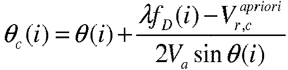
- Verfahren nach Anspruch 3, dadurch gekennzeichnet, dass die Winkelposition θc(i) des Ziels durch einen Messwertversatz

- Verfahren nach Anspruch 4, dadurch gekennzeichnet, dass der Messwertversatz δθ auf der Basis der Differenz zwischen den Mittelwerten der Winkelpositionen der Antenne und den Mittelwerten der Winkelpositionen des Ziels bestimmt wird.
- Verfahren nach Anspruch 4, dadurch gekennzeichnet, dass der Messwertversatz δθ auf der Basis eines Wertes der Radialgeschwindigkeit des Ziels bestimmt wird, geliefert (614) mit Mitteln (613) zum Verfolgen des Ziels.
- Verfahren nach einem der vorherigen Ansprüche, dadurch gekennzeichnet, dass die Winkelpositionen Peil- und Azimutwinkel sind.
- Verfahren nach einem der vorherigen Ansprüche, dadurch gekennzeichnet, dass der Träger (300) ein Luftfahrzeug ist.
- Verfahren nach einem der vorherigen Ansprüche, dadurch gekennzeichnet, dass die Radialgeschwindigkeit des Trägers (300) durch eine Trägheitseinheit an Bord des Trägers geschätzt wird.
- Überwachungsradar (600), das wenigstens eine steuerbare Antenne (601), Mittel (603) zum Emittieren eines Radarsignals in Form von Impulsen, Mittel (604) zum Empfangen von durch die Reflexion der Impulse an der Umgebung erzeugten Echos, Mittel (615, 616) zum Schätzen der Winkelposition der Antenne, Mittel (606) zum Schätzen der Doppler-Frequenz der ein oder mehreren empfangenen Echos, Mittel (608) zum Paaren der Winkelposition der Antenne und der Doppler-Frequenz umfasst, wobei das Radar ferner zum Implementieren der Schritte des Verfahrens nach einem der Ansprüche 1 bis 9 ausgelegt ist.
Applications Claiming Priority (1)
| Application Number | Priority Date | Filing Date | Title |
|---|---|---|---|
| FR1004559A FR2967787B1 (fr) | 2010-11-23 | 2010-11-23 | Procede d'estimation de la position angulaire d'une cible par detection radar et radar mettant en oeuvre le procede |
Publications (2)
| Publication Number | Publication Date |
|---|---|
| EP2455778A1 EP2455778A1 (de) | 2012-05-23 |
| EP2455778B1 true EP2455778B1 (de) | 2016-11-02 |
Family
ID=44170236
Family Applications (1)
| Application Number | Title | Priority Date | Filing Date |
|---|---|---|---|
| EP11188335.1A Active EP2455778B1 (de) | 2010-11-23 | 2011-11-08 | Schätzverfahren der Winkelposition eines Ziels durch Radarerfassung, und Radar, bei dem dieses Verfahren umgesetzt wird |
Country Status (3)
| Country | Link |
|---|---|
| US (1) | US8816897B2 (de) |
| EP (1) | EP2455778B1 (de) |
| FR (1) | FR2967787B1 (de) |
Families Citing this family (7)
| Publication number | Priority date | Publication date | Assignee | Title |
|---|---|---|---|---|
| FR3050829A1 (fr) * | 2016-04-29 | 2017-11-03 | Thales Sa | Procede d'optimisation de la detection de cibles marines et radar aeroporte mettant en oeuvre un tel procede |
| CN111157986B (zh) * | 2020-01-03 | 2021-10-12 | 中南大学 | 基于扩展贝塞尔模型的多普勒穿墙雷达定位方法 |
| CN111505592A (zh) * | 2020-04-26 | 2020-08-07 | 中国科学院国家空间科学中心 | 一种利用底视差分干涉实现星载雷达横滚角测定的方法 |
| CN111562568B (zh) * | 2020-04-30 | 2022-05-24 | 北京卫星信息工程研究所 | 雷达发射端、接收端、频率同步方法和收发组网雷达 |
| CN111812608B (zh) * | 2020-06-15 | 2023-06-23 | 西安电子科技大学 | 基于mtd脉冲积累及模态分解的雷达目标方位角估计方法 |
| CN112147588B (zh) * | 2020-10-14 | 2022-03-01 | 中国电波传播研究所(中国电子科技集团公司第二十二研究所) | 一种不对称的雷达照射面积快速计算方法 |
| CN112305530B (zh) * | 2020-11-02 | 2022-12-23 | 上海神添实业有限公司 | 一种无人机群目标检测方法、电子设备及存储介质 |
Family Cites Families (3)
| Publication number | Priority date | Publication date | Assignee | Title |
|---|---|---|---|---|
| FR1604953A (de) * | 1960-08-20 | 1972-06-26 | ||
| US4034373A (en) * | 1973-11-08 | 1977-07-05 | Rca Corporation | Airborne moving-target indicating radar system |
| SE513210C2 (sv) * | 1998-10-30 | 2000-07-31 | Ericsson Telefon Ab L M | Förfarande för att fastställa rörelsedata för objekt |
-
2010
- 2010-11-23 FR FR1004559A patent/FR2967787B1/fr not_active Expired - Fee Related
-
2011
- 2011-11-08 EP EP11188335.1A patent/EP2455778B1/de active Active
- 2011-11-15 US US13/297,146 patent/US8816897B2/en not_active Expired - Fee Related
Non-Patent Citations (1)
| Title |
|---|
| J. C. CURLANDER AND R. N. MCDONOUGH: "Synthetic Aperture Radar - Systems and Signal Processing (passage)", 1 January 1991, JOHN WILEY AND SONS, New York, NY, USA, ISBN: 0-471-85770-X, pages: 16 - 21, XP007921734 * |
Also Published As
| Publication number | Publication date |
|---|---|
| US20120127025A1 (en) | 2012-05-24 |
| FR2967787B1 (fr) | 2012-12-14 |
| FR2967787A1 (fr) | 2012-05-25 |
| US8816897B2 (en) | 2014-08-26 |
| EP2455778A1 (de) | 2012-05-23 |
Similar Documents
| Publication | Publication Date | Title |
|---|---|---|
| EP2455778B1 (de) | Schätzverfahren der Winkelposition eines Ziels durch Radarerfassung, und Radar, bei dem dieses Verfahren umgesetzt wird | |
| WO2016202748A1 (fr) | Procede et dispositif de localisation d'une source d'emission electromagnetique et systeme mettant en œuvre un tel procede | |
| EP2287633B1 (de) | Radar zur Erkennung von Luftzielen, der als Ausrüstung eines Luftfahrzeugs dient, insbesondere zur Hindernisumfliegung | |
| EP2515140B1 (de) | Verfahren zur globalen akustischen Positionierung eines Ziels im Wasser oder unter Wasser | |
| FR2722005A1 (fr) | Appareil et procede pour attenuer les ambiguites dans les radars doppler a impulsions | |
| FR2913774A1 (fr) | Dispositif et procede de localisation d'un mobile a l'approche d'une surface reflechissant les ondes electromagnetiques | |
| WO2012123202A1 (fr) | Procede de surveillance radar et d'acquisition de signaux radar | |
| EP1671152A1 (de) | Verfahren und einrichtung zum filtern von antworten in einem sekundär-radar-extraktor | |
| EP3391072B1 (de) | Verfahren zur ortung von quellen mit emission elektromagnetischer impulse | |
| CA2901647C (fr) | Procede et dispositif sonar de determination de la vitesse de deplacement d'un vehicle naval par rapport au fond marin | |
| FR2947052A1 (fr) | Procede de mesure de vitesse d'un aeronef, par anemometrie laser doppler | |
| FR3070766B1 (fr) | Systeme radar de poursuite ameliore | |
| EP3538916B1 (de) | Verfahren zum testen der elektromagnetischen verträglichkeit eines radardetektors mit mindestens einem impulssignalsender an bord | |
| WO2013045231A1 (fr) | Dispositif de detection et de localisation de mobiles equipes de radars et procede associe | |
| EP1324065B1 (de) | Verfahren zur passiven Lokalisierung eines Zieles und insbesondere zur Luft-Luftlokalisierung | |
| WO2021110868A1 (fr) | Procédé et dispositif de mesure de hauteur d'un aéronef en vol par rapport à au moins un point du sol | |
| FR2550347A1 (fr) | Perfectionnements aux radars doppler a impulsions | |
| EP3538919B1 (de) | Verfahren zum testen der elektromagnetischen verträglichkeit eines radardetektors mit mindestens einem impulssignalgeber an bord | |
| EP3538917B1 (de) | Verfahren zum testen der elektromagnetischen verträglichkeit eines radardetektors mit mindestens einem impulssignalgeber an bord | |
| EP3391077B1 (de) | Verfahren zur ortung elektromagnetischer impulsemissionsquellen in einer umgebung mit reflektoren | |
| WO2023174774A1 (fr) | Système radar et procédé associé pour optimiser l'élimination de fouillis radar | |
| FR3140177A1 (fr) | Procédé et dispositif de détection d’obstacles proches par Radar Passif Multistatique GNSS pour plateformes mobiles | |
| FR2955671A1 (fr) | Procede de detection de cibles marines et dispositif associe | |
| FR2988177A1 (fr) | Procede de pistage passif d'au moins un emetteur electromagnetique exterieur a une plateforme et ensemble de pistage associe | |
| EP2255148A2 (de) | Kostengünstiges schusssteuerungssystem zum schiessen auf fixe und bewegliche ziele |
Legal Events
| Date | Code | Title | Description |
|---|---|---|---|
| PUAI | Public reference made under article 153(3) epc to a published international application that has entered the european phase |
Free format text: ORIGINAL CODE: 0009012 |
|
| AK | Designated contracting states |
Kind code of ref document: A1 Designated state(s): AL AT BE BG CH CY CZ DE DK EE ES FI FR GB GR HR HU IE IS IT LI LT LU LV MC MK MT NL NO PL PT RO RS SE SI SK SM TR |
|
| AX | Request for extension of the european patent |
Extension state: BA ME |
|
| 17P | Request for examination filed |
Effective date: 20121030 |
|
| 17Q | First examination report despatched |
Effective date: 20130412 |
|
| GRAP | Despatch of communication of intention to grant a patent |
Free format text: ORIGINAL CODE: EPIDOSNIGR1 |
|
| INTG | Intention to grant announced |
Effective date: 20160617 |
|
| GRAS | Grant fee paid |
Free format text: ORIGINAL CODE: EPIDOSNIGR3 |
|
| GRAA | (expected) grant |
Free format text: ORIGINAL CODE: 0009210 |
|
| RAP1 | Party data changed (applicant data changed or rights of an application transferred) |
Owner name: THALES |
|
| REG | Reference to a national code |
Ref country code: FR Ref legal event code: PLFP Year of fee payment: 6 |
|
| AK | Designated contracting states |
Kind code of ref document: B1 Designated state(s): AL AT BE BG CH CY CZ DE DK EE ES FI FR GB GR HR HU IE IS IT LI LT LU LV MC MK MT NL NO PL PT RO RS SE SI SK SM TR |
|
| REG | Reference to a national code |
Ref country code: GB Ref legal event code: FG4D Free format text: NOT ENGLISH |
|
| REG | Reference to a national code |
Ref country code: AT Ref legal event code: REF Ref document number: 842387 Country of ref document: AT Kind code of ref document: T Effective date: 20161115 Ref country code: CH Ref legal event code: EP |
|
| REG | Reference to a national code |
Ref country code: IE Ref legal event code: FG4D Free format text: LANGUAGE OF EP DOCUMENT: FRENCH |
|
| REG | Reference to a national code |
Ref country code: DE Ref legal event code: R096 Ref document number: 602011031844 Country of ref document: DE |
|
| PG25 | Lapsed in a contracting state [announced via postgrant information from national office to epo] |
Ref country code: LV Free format text: LAPSE BECAUSE OF FAILURE TO SUBMIT A TRANSLATION OF THE DESCRIPTION OR TO PAY THE FEE WITHIN THE PRESCRIBED TIME-LIMIT Effective date: 20161102 |
|
| REG | Reference to a national code |
Ref country code: NL Ref legal event code: MP Effective date: 20161102 |
|
| REG | Reference to a national code |
Ref country code: LT Ref legal event code: MG4D |
|
| REG | Reference to a national code |
Ref country code: AT Ref legal event code: MK05 Ref document number: 842387 Country of ref document: AT Kind code of ref document: T Effective date: 20161102 |
|
| PG25 | Lapsed in a contracting state [announced via postgrant information from national office to epo] |
Ref country code: NO Free format text: LAPSE BECAUSE OF FAILURE TO SUBMIT A TRANSLATION OF THE DESCRIPTION OR TO PAY THE FEE WITHIN THE PRESCRIBED TIME-LIMIT Effective date: 20170202 Ref country code: LT Free format text: LAPSE BECAUSE OF FAILURE TO SUBMIT A TRANSLATION OF THE DESCRIPTION OR TO PAY THE FEE WITHIN THE PRESCRIBED TIME-LIMIT Effective date: 20161102 Ref country code: GR Free format text: LAPSE BECAUSE OF FAILURE TO SUBMIT A TRANSLATION OF THE DESCRIPTION OR TO PAY THE FEE WITHIN THE PRESCRIBED TIME-LIMIT Effective date: 20170203 Ref country code: NL Free format text: LAPSE BECAUSE OF FAILURE TO SUBMIT A TRANSLATION OF THE DESCRIPTION OR TO PAY THE FEE WITHIN THE PRESCRIBED TIME-LIMIT Effective date: 20161102 Ref country code: SE Free format text: LAPSE BECAUSE OF FAILURE TO SUBMIT A TRANSLATION OF THE DESCRIPTION OR TO PAY THE FEE WITHIN THE PRESCRIBED TIME-LIMIT Effective date: 20161102 |
|
| PG25 | Lapsed in a contracting state [announced via postgrant information from national office to epo] |
Ref country code: HR Free format text: LAPSE BECAUSE OF FAILURE TO SUBMIT A TRANSLATION OF THE DESCRIPTION OR TO PAY THE FEE WITHIN THE PRESCRIBED TIME-LIMIT Effective date: 20161102 Ref country code: ES Free format text: LAPSE BECAUSE OF FAILURE TO SUBMIT A TRANSLATION OF THE DESCRIPTION OR TO PAY THE FEE WITHIN THE PRESCRIBED TIME-LIMIT Effective date: 20161102 Ref country code: IS Free format text: LAPSE BECAUSE OF FAILURE TO SUBMIT A TRANSLATION OF THE DESCRIPTION OR TO PAY THE FEE WITHIN THE PRESCRIBED TIME-LIMIT Effective date: 20170302 Ref country code: PT Free format text: LAPSE BECAUSE OF FAILURE TO SUBMIT A TRANSLATION OF THE DESCRIPTION OR TO PAY THE FEE WITHIN THE PRESCRIBED TIME-LIMIT Effective date: 20170302 Ref country code: FI Free format text: LAPSE BECAUSE OF FAILURE TO SUBMIT A TRANSLATION OF THE DESCRIPTION OR TO PAY THE FEE WITHIN THE PRESCRIBED TIME-LIMIT Effective date: 20161102 Ref country code: PL Free format text: LAPSE BECAUSE OF FAILURE TO SUBMIT A TRANSLATION OF THE DESCRIPTION OR TO PAY THE FEE WITHIN THE PRESCRIBED TIME-LIMIT Effective date: 20161102 Ref country code: AT Free format text: LAPSE BECAUSE OF FAILURE TO SUBMIT A TRANSLATION OF THE DESCRIPTION OR TO PAY THE FEE WITHIN THE PRESCRIBED TIME-LIMIT Effective date: 20161102 Ref country code: BE Free format text: LAPSE BECAUSE OF NON-PAYMENT OF DUE FEES Effective date: 20161130 Ref country code: RS Free format text: LAPSE BECAUSE OF FAILURE TO SUBMIT A TRANSLATION OF THE DESCRIPTION OR TO PAY THE FEE WITHIN THE PRESCRIBED TIME-LIMIT Effective date: 20161102 |
|
| REG | Reference to a national code |
Ref country code: CH Ref legal event code: PL |
|
| PG25 | Lapsed in a contracting state [announced via postgrant information from national office to epo] |
Ref country code: SK Free format text: LAPSE BECAUSE OF FAILURE TO SUBMIT A TRANSLATION OF THE DESCRIPTION OR TO PAY THE FEE WITHIN THE PRESCRIBED TIME-LIMIT Effective date: 20161102 Ref country code: LI Free format text: LAPSE BECAUSE OF NON-PAYMENT OF DUE FEES Effective date: 20161130 Ref country code: EE Free format text: LAPSE BECAUSE OF FAILURE TO SUBMIT A TRANSLATION OF THE DESCRIPTION OR TO PAY THE FEE WITHIN THE PRESCRIBED TIME-LIMIT Effective date: 20161102 Ref country code: CZ Free format text: LAPSE BECAUSE OF FAILURE TO SUBMIT A TRANSLATION OF THE DESCRIPTION OR TO PAY THE FEE WITHIN THE PRESCRIBED TIME-LIMIT Effective date: 20161102 Ref country code: RO Free format text: LAPSE BECAUSE OF FAILURE TO SUBMIT A TRANSLATION OF THE DESCRIPTION OR TO PAY THE FEE WITHIN THE PRESCRIBED TIME-LIMIT Effective date: 20161102 Ref country code: DK Free format text: LAPSE BECAUSE OF FAILURE TO SUBMIT A TRANSLATION OF THE DESCRIPTION OR TO PAY THE FEE WITHIN THE PRESCRIBED TIME-LIMIT Effective date: 20161102 Ref country code: CH Free format text: LAPSE BECAUSE OF NON-PAYMENT OF DUE FEES Effective date: 20161130 |
|
| REG | Reference to a national code |
Ref country code: DE Ref legal event code: R097 Ref document number: 602011031844 Country of ref document: DE |
|
| REG | Reference to a national code |
Ref country code: IE Ref legal event code: MM4A |
|
| PG25 | Lapsed in a contracting state [announced via postgrant information from national office to epo] |
Ref country code: SM Free format text: LAPSE BECAUSE OF FAILURE TO SUBMIT A TRANSLATION OF THE DESCRIPTION OR TO PAY THE FEE WITHIN THE PRESCRIBED TIME-LIMIT Effective date: 20161102 Ref country code: BG Free format text: LAPSE BECAUSE OF FAILURE TO SUBMIT A TRANSLATION OF THE DESCRIPTION OR TO PAY THE FEE WITHIN THE PRESCRIBED TIME-LIMIT Effective date: 20170202 |
|
| PLBE | No opposition filed within time limit |
Free format text: ORIGINAL CODE: 0009261 |
|
| STAA | Information on the status of an ep patent application or granted ep patent |
Free format text: STATUS: NO OPPOSITION FILED WITHIN TIME LIMIT |
|
| PG25 | Lapsed in a contracting state [announced via postgrant information from national office to epo] |
Ref country code: MC Free format text: LAPSE BECAUSE OF FAILURE TO SUBMIT A TRANSLATION OF THE DESCRIPTION OR TO PAY THE FEE WITHIN THE PRESCRIBED TIME-LIMIT Effective date: 20161102 Ref country code: LU Free format text: LAPSE BECAUSE OF NON-PAYMENT OF DUE FEES Effective date: 20161130 |
|
| 26N | No opposition filed |
Effective date: 20170803 |
|
| REG | Reference to a national code |
Ref country code: FR Ref legal event code: PLFP Year of fee payment: 7 |
|
| PG25 | Lapsed in a contracting state [announced via postgrant information from national office to epo] |
Ref country code: IE Free format text: LAPSE BECAUSE OF NON-PAYMENT OF DUE FEES Effective date: 20161108 Ref country code: SI Free format text: LAPSE BECAUSE OF FAILURE TO SUBMIT A TRANSLATION OF THE DESCRIPTION OR TO PAY THE FEE WITHIN THE PRESCRIBED TIME-LIMIT Effective date: 20161102 |
|
| REG | Reference to a national code |
Ref country code: BE Ref legal event code: MM Effective date: 20161130 |
|
| PG25 | Lapsed in a contracting state [announced via postgrant information from national office to epo] |
Ref country code: CY Free format text: LAPSE BECAUSE OF FAILURE TO SUBMIT A TRANSLATION OF THE DESCRIPTION OR TO PAY THE FEE WITHIN THE PRESCRIBED TIME-LIMIT Effective date: 20161102 Ref country code: HU Free format text: LAPSE BECAUSE OF FAILURE TO SUBMIT A TRANSLATION OF THE DESCRIPTION OR TO PAY THE FEE WITHIN THE PRESCRIBED TIME-LIMIT; INVALID AB INITIO Effective date: 20111108 |
|
| PG25 | Lapsed in a contracting state [announced via postgrant information from national office to epo] |
Ref country code: TR Free format text: LAPSE BECAUSE OF FAILURE TO SUBMIT A TRANSLATION OF THE DESCRIPTION OR TO PAY THE FEE WITHIN THE PRESCRIBED TIME-LIMIT Effective date: 20161102 Ref country code: MK Free format text: LAPSE BECAUSE OF FAILURE TO SUBMIT A TRANSLATION OF THE DESCRIPTION OR TO PAY THE FEE WITHIN THE PRESCRIBED TIME-LIMIT Effective date: 20161102 |
|
| PG25 | Lapsed in a contracting state [announced via postgrant information from national office to epo] |
Ref country code: MT Free format text: LAPSE BECAUSE OF FAILURE TO SUBMIT A TRANSLATION OF THE DESCRIPTION OR TO PAY THE FEE WITHIN THE PRESCRIBED TIME-LIMIT Effective date: 20161102 |
|
| REG | Reference to a national code |
Ref country code: FR Ref legal event code: PLFP Year of fee payment: 8 |
|
| PG25 | Lapsed in a contracting state [announced via postgrant information from national office to epo] |
Ref country code: AL Free format text: LAPSE BECAUSE OF FAILURE TO SUBMIT A TRANSLATION OF THE DESCRIPTION OR TO PAY THE FEE WITHIN THE PRESCRIBED TIME-LIMIT Effective date: 20161102 |
|
| P01 | Opt-out of the competence of the unified patent court (upc) registered |
Effective date: 20230427 |
|
| PGFP | Annual fee paid to national office [announced via postgrant information from national office to epo] |
Ref country code: GB Payment date: 20231019 Year of fee payment: 13 |
|
| PGFP | Annual fee paid to national office [announced via postgrant information from national office to epo] |
Ref country code: IT Payment date: 20231026 Year of fee payment: 13 Ref country code: FR Payment date: 20231024 Year of fee payment: 13 Ref country code: DE Payment date: 20231017 Year of fee payment: 13 |