EP2455774A1 - Sensor device and method for its operation - Google Patents
Sensor device and method for its operation Download PDFInfo
- Publication number
- EP2455774A1 EP2455774A1 EP10191838A EP10191838A EP2455774A1 EP 2455774 A1 EP2455774 A1 EP 2455774A1 EP 10191838 A EP10191838 A EP 10191838A EP 10191838 A EP10191838 A EP 10191838A EP 2455774 A1 EP2455774 A1 EP 2455774A1
- Authority
- EP
- European Patent Office
- Prior art keywords
- capacitor
- detector
- sensor device
- induction coil
- magnetic field
- Prior art date
- Legal status (The legal status is an assumption and is not a legal conclusion. Google has not performed a legal analysis and makes no representation as to the accuracy of the status listed.)
- Granted
Links
- 238000000034 method Methods 0.000 title claims abstract description 15
- 230000005291 magnetic effect Effects 0.000 claims abstract description 55
- 239000002245 particle Substances 0.000 claims abstract description 44
- 239000012530 fluid Substances 0.000 claims abstract description 37
- 230000006698 induction Effects 0.000 claims abstract description 37
- 230000005294 ferromagnetic effect Effects 0.000 claims abstract description 19
- 230000003287 optical effect Effects 0.000 claims abstract description 8
- 239000003990 capacitor Substances 0.000 claims description 63
- 230000004907 flux Effects 0.000 claims description 13
- 239000000314 lubricant Substances 0.000 claims description 5
- 230000001939 inductive effect Effects 0.000 claims description 4
- 230000005540 biological transmission Effects 0.000 claims description 3
- 238000007599 discharging Methods 0.000 claims description 3
- 230000004044 response Effects 0.000 claims description 2
- 239000010705 motor oil Substances 0.000 claims 1
- 238000004140 cleaning Methods 0.000 description 12
- 230000008569 process Effects 0.000 description 7
- XEEYBQQBJWHFJM-UHFFFAOYSA-N Iron Chemical compound [Fe] XEEYBQQBJWHFJM-UHFFFAOYSA-N 0.000 description 6
- 238000010586 diagram Methods 0.000 description 5
- 238000011109 contamination Methods 0.000 description 3
- 238000001514 detection method Methods 0.000 description 3
- 238000005299 abrasion Methods 0.000 description 2
- 230000002349 favourable effect Effects 0.000 description 2
- 230000001965 increasing effect Effects 0.000 description 2
- 229910052742 iron Inorganic materials 0.000 description 2
- 238000004519 manufacturing process Methods 0.000 description 2
- 229910000831 Steel Inorganic materials 0.000 description 1
- 238000009825 accumulation Methods 0.000 description 1
- 230000033228 biological regulation Effects 0.000 description 1
- 230000008859 change Effects 0.000 description 1
- 238000013016 damping Methods 0.000 description 1
- 230000001419 dependent effect Effects 0.000 description 1
- 238000004146 energy storage Methods 0.000 description 1
- 239000003302 ferromagnetic material Substances 0.000 description 1
- 238000012423 maintenance Methods 0.000 description 1
- 230000007257 malfunction Effects 0.000 description 1
- 230000035945 sensitivity Effects 0.000 description 1
- 238000004904 shortening Methods 0.000 description 1
- 239000010959 steel Substances 0.000 description 1
- 230000001960 triggered effect Effects 0.000 description 1
- 238000004804 winding Methods 0.000 description 1
Images

Classifications
-
- G—PHYSICS
- G01—MEASURING; TESTING
- G01R—MEASURING ELECTRIC VARIABLES; MEASURING MAGNETIC VARIABLES
- G01R33/00—Arrangements or instruments for measuring magnetic variables
- G01R33/12—Measuring magnetic properties of articles or specimens of solids or fluids
-
- G—PHYSICS
- G01—MEASURING; TESTING
- G01N—INVESTIGATING OR ANALYSING MATERIALS BY DETERMINING THEIR CHEMICAL OR PHYSICAL PROPERTIES
- G01N15/00—Investigating characteristics of particles; Investigating permeability, pore-volume, or surface-area of porous materials
- G01N15/06—Investigating concentration of particle suspensions
- G01N15/0656—Investigating concentration of particle suspensions using electric, e.g. electrostatic methods or magnetic methods
-
- G—PHYSICS
- G01—MEASURING; TESTING
- G01N—INVESTIGATING OR ANALYSING MATERIALS BY DETERMINING THEIR CHEMICAL OR PHYSICAL PROPERTIES
- G01N33/00—Investigating or analysing materials by specific methods not covered by groups G01N1/00 - G01N31/00
- G01N33/26—Oils; viscous liquids; paints; inks
- G01N33/28—Oils, i.e. hydrocarbon liquids
- G01N33/2835—Oils, i.e. hydrocarbon liquids specific substances contained in the oil or fuel
- G01N33/2858—Oils, i.e. hydrocarbon liquids specific substances contained in the oil or fuel metal particles
Definitions
- the present invention relates to a sensor device for detecting ferromagnetic particles in a fluid.
- the invention further relates to a method for operating such a sensor device.
- Fluids such as hydraulic fluids and lubricants used in corresponding fluid power plants almost always have more or less contamination by ferromagnetic particles, i. Iron or steel particles, on. Such particles mostly enter the system during the production and maintenance of the system, but above all arise continuously by abrasion of moving components during operation of the system (to a particularly high degree, for example, in transmissions). Since too high a particle load of the fluid can impair the functioning of the system or even lead to total failure, it is necessary to monitor the particle load in order to be able to take suitable measures when a certain limit value is reached, which may vary depending on the type of fluidic system (eg replacement or cleaning of particulate filters, replacement of the fluid, cleaning of the entire system, etc.).
- ferromagnetic particles i. Iron or steel particles
- Sensors are known for the detection of ferromagnetic particles in which a permanent magnet protrudes into the fluid flowing past, with ferromagnetic particles contained in the fluid being deposited on the magnet. This attachment leads to a change in the magnetic field, which can be detected with a suitable detector (eg a Hall detector).
- a suitable detector eg a Hall detector
- Such a device is eg in the GB 2 029 580 A described.
- a disadvantage of these sensors is the fact that the adhering to the permanent magnet particles must be removed again (at the latest when the maximum capacity of the magnet is reached). For this purpose, the sensor must either be replaced or removed and manually cleaned, which is a relatively high cost, or the deposited particles are removed by means of a brush or the like installed as part of the sensor.
- a sensor with such moving mechanical components is expensive to manufacture and more susceptible to malfunction.
- the invention is therefore based on the object to propose a sensor device that can be operated continuously in a simple manner.
- the core idea of the invention is not to remove the adhering particles manually or mechanically from the permanent magnet but by compensating the magnetic field of the permanent magnet by an induced, oppositely directed magnetic field so that no attraction force acts on the particles and these be entrained by the passing fluid.
- the discharge of the at least one capacitor is provided according to the invention via the induction coil.
- the capacitance of the at least one capacitor and the inductance of the coil are matched to one another such that during the discharge of the fully charged capacitor, first a maximum magnetic field is induced, which is stronger than the magnetic field of the permanent magnet, so that this is "overcompensated".
- the cleaning of the sensor surface by the discharge of the at least one capacitor can be triggered in response to a signal from the detector either manually or by an automatic control, as will be described in detail below.
- the sensor device according to the invention can be operated continuously, without having to be replaced or removed for cleaning.
- the length of the period between two required cleanings is a measure of the particle load of the fluid.
- the sensor surface is favorably a flat surface, wherein the magnetic field lines of the permanent magnet are at least partially oriented perpendicular to the flat surface.
- a magnetic force of attraction acts on the ferromagnetic particles in a fluid flowing past, to which the sensor surface is exposed, so that the particles accumulate on the sensor surface.
- the flow direction of the fluid is preferably parallel to the sensor surface.
- the sensor surface is formed by a magnetic flux guide connected to the permanent magnet.
- the permanent magnet is thus not in direct contact with the fluid, but the magnetic field in the region of the sensor surface is generated indirectly via the magnetic flux guide.
- the magnetic flux guide preferably comprises a ferromagnetic material, in particular iron, and its geometry can be adapted to the spatial conditions at the location of use of the sensor device.
- the induction coil which is provided according to the invention, may surround the permanent magnet or the optionally provided magnetic flux guide.
- the permanent magnet or the magnetic flux guide thus form, together with the induction coil, an electromagnet whose magnetic field is directed counter to the magnetic field of the permanent magnet when an electric current flows through the induction coil.
- the at least one capacitor may be switchable with the induction coil in series or in parallel, i. the at least one capacitor and the induction coil can be interconnected in the manner of a resonant circuit during the discharge process.
- the capacitance of the at least one capacitor must be matched to the inductance of the coil, so that at the beginning of the discharge process, a magnetic field can be induced which overcompensates the magnetic field of the permanent magnet.
- the required capacity of the at least one capacitor also depends on the strength of the permanent magnet.
- the capacitance of the at least one capacitor is relatively large and is typically in the range of several Farad, depending on the coil, for example in the range of about 3 F to about 10 F.
- the at least one capacitor comprises a double-layer capacitor. Such capacitors are typically used as energy storage.
- the discharge process of the at least one capacitor via the induction coil usually takes a few seconds, and is dependent inter alia on the inductance of the coil and optionally an additional damping or winding resistance.
- the decay of the induced magnetic field during the discharge process from a maximum value (in which the magnetic field of the permanent magnet is overcompensated) down to zero corresponds to a creep or an aperiodic limit case.
- the capacitors may be connected in parallel to increase the total capacitance or in series to limit the voltage applied to each individual capacitor during the charging process.
- the sensor device comprises a current source with voltage limitation, by means of which the at least one capacitor can be charged.
- the voltage source comprises a power supply which supplies a relatively low voltage (typically about 2 to 3 V), since suitable capacitors, in particular double-layer capacitors, do not tolerate higher voltages.
- a relatively low voltage typically about 2 to 3 V
- suitable capacitors in particular double-layer capacitors, do not tolerate higher voltages.
- the current source allows a limitation of the charging current.
- the induction coil can be switched without current when charging the at least one capacitor.
- the charging of the capacitor can therefore be independent of the induction coil, so that the magnetic field of the permanent magnet is not affected by the charging process, which typically takes a few minutes.
- This also applies to the time between the charging and the discharge of the at least one capacitor, during which increasingly ferromagnetic particles are deposited on the sensor surface.
- the time between two cleanings of the sensor surface can be several days to several weeks.
- the at least one capacitor can be recharged as needed be, if it comes as a result of a self-discharge to a voltage drop.
- the detector of the sensor device according to the invention provides a signal which serves as a measure of the loading of the fluid with ferromagnetic particles. However, this only applies until a maximum amount of particles is attached to the sensor surface, i. until a kind of saturation occurs.
- Detectors which can be used in the invention include e.g. Fe resonance detectors, interdigital capacitors (IDK), Hall detectors, resistive detectors and optical detectors. The various detectors differ in part in their sensitivity and the maximum detectable amount of particles, so that a suitable detector depending on the expected or tolerable particle load of the fluid power plant can be selected.
- an IDK is relatively sensitive and already reacts to the accumulation of fewer particles, so that it can be used in particular in a sensor device for hydraulic systems.
- a less sensitive Hall detector can be used in systems with high abrasion, e.g. for detecting the particle load of transmission oil.
- the sensor device further comprises an optical or acoustic display means connected to the detector, by means of which a signal of the detector can be displayed.
- the display means may either continuously display the signal of the detector (eg in the form of a digital display or a pointer instrument) or the display means may only indicate when the signal reaches a predetermined threshold (eg in the form of a warning light or a beep).
- the predetermined threshold corresponds to a certain amount of particles attached to the sensor surface, which particle size may be less than or equal to the maximum capacitance of the sensor surface (saturation).
- the display means may directly display a continuous signal of the detector (eg, a voltage or a current) or indirectly via a signal converter, an interface, or the like.
- the sensor device comprises a switching device, by means of which the discharge of the at least one capacitor via the induction coil can be initiated manually.
- the user can perform cleaning of the sensor surface, if necessary, by e.g. operated a switch or button, whereby the at least one capacitor is discharged and then recharged.
- the decision as to when a cleaning is required can be made by the user on the basis of the optical or acoustic display means, and if the detector signal is displayed continuously, he has the possibility to set a suitable threshold himself.
- the sensor device comprises a control unit connected to the detector, by means of which the discharge of the at least one capacitor in dependence on a signal of the detector is controllable.
- the cleaning of the sensor surface is carried out automatically by a respective discharge of the capacitor is initiated by the control unit as soon as the detector signal reaches a predetermined threshold.
- Display means for the detector signal are not absolutely necessary in this case, wherein optionally it can be provided that the cleaning of the sensor surface is displayed in each case. It is particularly advantageous if the time duration between two successive cleanings is stored and possibly displayed, since these times represent a measure of the particle load of the fluid. An increasing shortening of the cleaning cycles indicates that the contamination of the fluid with ferromagnetic particles increases and, if necessary, appropriate measures (eg replacement of filters) must be initiated.
- the fluid in the context of the present invention is in particular a lubricant or a hydraulic fluid, i. the sensor device according to the invention can be used for the detection of ferromagnetic particles in the lubricant circuit of gears or motors (both in vehicles and stationary systems), or in various hydraulic systems.
- the sensor device can each be arranged in the main circuit or in a secondary circuit of the corresponding system.
- the method can in particular be carried out automatically by controlling the charging and discharging of the at least one capacitor by means of a control unit as a function of the signal of the detector.
- the induction coil is switched off during charging of the at least one capacitor. This avoids influencing the magnetic field of the permanent magnet during charging of the at least one capacitor.
- FIG. 1 schematically shows the basic structure of a sensor device 10 according to the present invention for the detection of ferromagnetic particles 12 in a fluid 14.
- the fluid 14 eg, a lubricant or a hydraulic fluid
- the fluid 14 is located in a fluid circuit and moves in a conduit 16 along a flow direction 18th ,
- the sensor device 10 comprises a magnetic flux guide 20, which projects laterally into the line 16.
- An end face of the magnetic flux guide 20 forms a planar sensor surface 22, which is exposed to the fluid 14 and is oriented parallel to the flow direction 18.
- the opposite end face of the magnetic flux guide 20 is connected to a permanent magnet 24 having a north pole 26 and a south pole 28.
- the permanent magnet 24 generates via the magnetic flux guide 20, a magnetic field in the region of the sensor surface 22, the field lines are oriented at least partially perpendicular to the planar sensor surface 22. As a result, ferromagnetic particles 12 are attracted and deposit on the sensor surface 22.
- the sensor device 10 further includes an induction coil 30 surrounding the magnetic flux guide 20. With the induction coil 30, a magnetic field is inducible, which is directed opposite to the magnetic field of the permanent magnet 24.
- the sensor device 10 also comprises a number of other components which are included in the FIG. 1 are not shown for reasons of clarity, and their function results from the circuit diagrams described below.
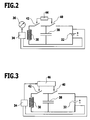
- FIG. 2 shows a schematic circuit diagram of a first embodiment of the sensor device 10 according to the invention.
- the sensor device 10 includes a voltage limited current source 32 (e.g., a power supply) to which a detector 34 is connected. By means of the detector 34, the ferromagnetic particles 12 deposited in the region of the sensor surface 22 can be detected.
- the detector 34 may be e.g. a Fe resonance detector, an IDK, a Hall detector, a resistive detector or an optical detector.
- An optical or acoustic display means 36 is connected to the detector 34 for displaying a signal of the detector 34, which represents a measure of the amount of particles 12 deposited on the sensor surface 22.
- the display means 36 may continuously display the detector signal (e.g., as a pointer instrument) or only when a predetermined threshold threshold is exceeded (e.g., as an LED).
- the sensor device 10 further includes a capacitor 38 that can be charged by the current source 32 when a first switch 40 is closed.
- the capacitor 38 is discharged via the induction coil 30 when a second switch 42 is closed.
- the capacitor 38 has a sufficiently high capacity, depending on the type of induction coil 30, for example in the range of about 3 to about 10 F. Suitable for this example is a double-layer capacitor.
- a maximum magnetic field is induced by the coil 30 at the beginning, which is opposite and stronger than the magnetic field of the permanent magnet 24, ie this is initially overcompensated.
- the tension of the Capacitor 38 and the current in the coil 30 fall continuously in the further course of the discharge, so that the induced magnetic field inevitably passes through an area in which the magnetic field of the permanent magnet 24 is accurately compensated. In this case, the force of attraction acting on the particles 12 is released and the sensor surface 22 is cleaned of the particles 12.
- the entire discharge process of the capacitor 38 usually takes only a few seconds.
- the second switch 42 is opened, so that the induction coil 30 is de-energized during charging.
- the display means 36 continuously displays the signal of the detector 34 and / or signals the reaching of the threshold value.
- the user can briefly open the first switch 40 and close the second switch 42 by actuating a switching device 44, so that the sensor surface 22 is cleaned by the discharge of the capacitor 38 via the induction coil 30.
- the first switch 40 is closed again and the second switch 42 is opened, the capacitor 38 is recharged and particles 12 begin to accumulate on the sensor surface 22 again.
- the length of the periods between two required actuations of the switching device 44 are a measure of the particle load of the fluid 14th
- FIG. 3 shows a schematic circuit diagram of a second embodiment of the sensor device 10th
- a control unit 46 connected to the detector 34 is provided, by means of which the discharge of the capacitor 38 can be controlled in dependence on a signal of the detector 34.
- the control unit 46 thus replaces the manual operation of a switching device, so that the sensor device 10 are operated automatically over a longer period of time can.
- the first switch 40 is opened by the control unit 46 for a short time and the second switch 42 is closed.
- the discharge of the capacitor 38 via the induction coil 30 then takes place as described above.
- the lengths of the periods between two discharges of the capacitor 38 are detected and stored by the control unit 46 and are a measure of the particle load of the fluid 14. As these periods become shorter, the contamination of the fluid 14 has increased.
- a display means for the signal of the detector 34 is not required in this case, but may optionally be provided.
Abstract
Description
Die vorliegende Erfindung betrifft eine Sensorvorrichtung zur Detektion von ferromagnetischen Partikeln in einem Fluid.The present invention relates to a sensor device for detecting ferromagnetic particles in a fluid.
Die Erfindung betrifft ferner ein Verfahren zum Betrieb einer derartigen Sensorvorrichtung.The invention further relates to a method for operating such a sensor device.
Fluide wie Hydraulikflüssigkeiten und Schmiermittel, die in entsprechenden fluidtechnischen Anlagen eingesetzt werden, weisen fast immer eine mehr oder weniger starke Verschmutzung durch ferromagnetische Partikel, d.h. Eisen- bzw. Stahlpartikel, auf. Solche Partikel gelangen meist schon bei der Herstellung und Wartung der Anlage in das System, vor allem aber entstehen sie kontinuierlich durch Abrieb an beweglichen Komponenten während des Betriebs der Anlage (in besonders hohem Ausmaß z.B. bei Getrieben). Da eine zu hohe Partikelbelastung des Fluids die Funktionsfähigkeit der Anlage beeinträchtigen oder sogar zu einem Totalausfall führen kann, ist eine Überwachung der Partikelbelastung erforderlich, um bei Erreichen eines bestimmten Grenzwertes, der je nach Art der fluidtechnischen Anlage unterschiedlich sein kann, geeignete Maßnahmen ergreifen zu können (z.B. Austausch oder Reinigung von Partikelfiltern, Austausch des Fluids, Reinigung der gesamten Anlage usw.).Fluids such as hydraulic fluids and lubricants used in corresponding fluid power plants almost always have more or less contamination by ferromagnetic particles, i. Iron or steel particles, on. Such particles mostly enter the system during the production and maintenance of the system, but above all arise continuously by abrasion of moving components during operation of the system (to a particularly high degree, for example, in transmissions). Since too high a particle load of the fluid can impair the functioning of the system or even lead to total failure, it is necessary to monitor the particle load in order to be able to take suitable measures when a certain limit value is reached, which may vary depending on the type of fluidic system (eg replacement or cleaning of particulate filters, replacement of the fluid, cleaning of the entire system, etc.).
Es sind Sensoren zur Detektion von ferromagnetischen Partikeln bekannt, bei denen ein Permanentmagnet in das vorbeiströmende Fluid hineinragt, wobei sich in dem Fluid enthaltene ferromagentische Partikel an den Magneten anlagern. Diese Anlagerung führt zu einer Änderung des Magnetfeldes, welche mit einem geeigneten Detektor (z.B. einem Hall-Detektor) erfasst werden kann. Eine solche Vorrichtung wird z.B. in der
Der Erfindung liegt daher die Aufgabe zugrunde, eine Sensorvorrichtung vorzuschlagen, die auf einfache Weise kontinuierlich betrieben werden kann.The invention is therefore based on the object to propose a sensor device that can be operated continuously in a simple manner.
Diese Aufgabe wird erfindungsgemäß gelöst durch eine Sensorvorrichtung der eingangs genannten Art, umfassend
- eine Sensorfläche, die dem Fluid ausgesetzt ist;
- einen Permanentmagnet, der ein Magnetfeld im Bereich der Sensorfläche erzeugt;
- einen Detektor, mit dem ferromagnetische Partikel im Bereich der Sensorfläche detektierbar sind;
- eine Induktionsspule, mit der ein Magnetfeld induzierbar ist, das dem Magnetfeld des Permanentmagneten entgegen gerichtet ist; und
- mindestens einen Kondensator, der über die Induktionsspule entladbar ist, wobei durch die Entladung des mindestens einen Kondensators über die Induktionsspule ein maximales Magnetfeld induzierbar ist, welches stärker ist als das Magnetfeld des Permanentmagneten.
- a sensor surface exposed to the fluid;
- a permanent magnet which generates a magnetic field in the region of the sensor surface;
- a detector with which ferromagnetic particles in the region of the sensor surface are detectable;
- an induction coil, with which a magnetic field is inducible, which is directed opposite to the magnetic field of the permanent magnet; and
- at least one capacitor, which is dischargeable via the induction coil, wherein the discharge of the at least one capacitor via the induction coil, a maximum magnetic field is induced, which is stronger than the magnetic field of the permanent magnet.
Die Kernidee der Erfindung besteht darin, die anhaftenden Partikel nicht manuell bzw. mechanisch von dem Permanentmagneten zu entfernen, sondern dadurch, dass das Magnetfeld des Permanentmagneten durch ein induziertes, entgegen gerichtetes Magnetfeld kompensiert wird, so dass keine Anziehungskraft mehr auf die Partikel wirkt und diese von dem vorbeiströmenden Fluid mitgerissen werden. Um eine aufwändige Regelung zu vermeiden, die die Stromstärke in der Induktionsspule jeweils so abstimmt, dass das Magnetfeld des Permanentmagneten exakt kompensiert wird, ist erfindungsgemäß die Entladung des mindestens einen Kondensators über die Induktionsspule vorgesehen. Die Kapazität des mindestens einen Kondensators und die Induktivität der Spule sind dabei so aufeinander abgestimmt, dass bei der Entladung des vollständig aufgeladenen Kondensators zunächst ein maximales Magnetfeld induziert wird, welches stärker ist als das Magnetfeld des Permanentmagneten, sodass dieses "überkompensiert" wird. Da im weiteren Verlauf der Entladung die Spannung des mindestens einen Kondensators und damit die Stromstärke in der Induktionsspule kontinuierlich abnehmen, wird zwangsläufig zu einem bestimmten Zeitpunkt ein Bereich durchlaufen, in dem das Magnetfeld des Permanentmagneten genau kompensiert wird, d.h. die Summe der beiden Magnetfelder ist für eine bestimmte Zeitdauer so gering, dass die auf die ferromagnetischen Partikel wirkende Anziehungskraft geringer ist als die von dem vorbeiströmenden Fluid ausgeübte Kraft.The core idea of the invention is not to remove the adhering particles manually or mechanically from the permanent magnet but by compensating the magnetic field of the permanent magnet by an induced, oppositely directed magnetic field so that no attraction force acts on the particles and these be entrained by the passing fluid. To avoid a complicated regulation, which the Amperage in the induction coil in each case tuned so that the magnetic field of the permanent magnet is exactly compensated, the discharge of the at least one capacitor is provided according to the invention via the induction coil. The capacitance of the at least one capacitor and the inductance of the coil are matched to one another such that during the discharge of the fully charged capacitor, first a maximum magnetic field is induced, which is stronger than the magnetic field of the permanent magnet, so that this is "overcompensated". Since in the further course of the discharge, the voltage of the at least one capacitor and thus the current in the induction coil continuously decrease, inevitably passes through a range at a certain time, in which the magnetic field of the permanent magnet is compensated exactly, ie, the sum of the two magnetic fields is for a certain period of time so small that the force acting on the ferromagnetic particles attraction force is less than the force exerted by the passing fluid force.
Die Reinigung der Sensorfläche durch die Entladung des mindestens einen Kondensators kann in Abhängigkeit von einem Signal des Detektors entweder manuell oder durch eine automatische Steuerung ausgelöst werden, wie dies weiter unten im Einzelnen beschrieben wird. In beiden Fällen kann die erfindungsgemäße Sensorvorrichtung kontinuierlich betrieben werden, ohne dass sie ausgetauscht oder zur Reinigung entfernt werden muss. Die Länge des Zeitraumes zwischen zwei erforderlichen Reinigungen stellt dabei ein Maß für die Partikelbelastung des Fluids dar.The cleaning of the sensor surface by the discharge of the at least one capacitor can be triggered in response to a signal from the detector either manually or by an automatic control, as will be described in detail below. In both cases, the sensor device according to the invention can be operated continuously, without having to be replaced or removed for cleaning. The length of the period between two required cleanings is a measure of the particle load of the fluid.
Die Sensorfläche ist günstigerweise eine ebene Fläche, wobei die magnetischen Feldlinien des Permanentmagneten zumindest bereichsweise senkrecht zu der ebenen Fläche orientiert sind. Dadurch wirkt eine magnetische Anziehungskraft auf die ferromagnetischen Partikel in einem vorbeiströmenden Fluid, dem die Sensorfläche ausgesetzt ist, so dass sich die Partikel an der Sensorfläche anlagern. Die Strömungsrichtung des Fluids ist bevorzugt parallel zu der Sensorfläche.The sensor surface is favorably a flat surface, wherein the magnetic field lines of the permanent magnet are at least partially oriented perpendicular to the flat surface. As a result, a magnetic force of attraction acts on the ferromagnetic particles in a fluid flowing past, to which the sensor surface is exposed, so that the particles accumulate on the sensor surface. The flow direction of the fluid is preferably parallel to the sensor surface.
Bevorzugt wird die Sensorfläche durch eine mit dem Permanentmagneten verbundene Magnetflussführung gebildet. Der Permanentmagnet steht also nicht in direktem Kontakt mit dem Fluid, sondern das Magnetfeld im Bereich der Sensorfläche wird mittelbar über die Magnetflussführung erzeugt. Die Magnetflussführung umfasst bevorzugt ein ferromagnetisches Material, insbesondere Eisen, und kann in ihrer Geometrie an die räumlichen Gegebenheiten am Einsatzort der Sensorvorrichtung angepasst werden.Preferably, the sensor surface is formed by a magnetic flux guide connected to the permanent magnet. The permanent magnet is thus not in direct contact with the fluid, but the magnetic field in the region of the sensor surface is generated indirectly via the magnetic flux guide. The magnetic flux guide preferably comprises a ferromagnetic material, in particular iron, and its geometry can be adapted to the spatial conditions at the location of use of the sensor device.
Die Induktionsspule, die gemäß der Erfindung vorgesehen ist, kann den Permanentmagnet oder die gegebenenfalls vorgesehene Magnetflussführung umgeben. Der Permanentmagnet bzw. die Magnetflussführung bilden also zusammen mit der Induktionsspule einen Elektromagnet, dessen Magnetfeld dem Magnetfeld des Permanentmagneten entgegen gerichtet ist, wenn ein elektrischer Strom durch die Induktionsspule fließt.The induction coil, which is provided according to the invention, may surround the permanent magnet or the optionally provided magnetic flux guide. The permanent magnet or the magnetic flux guide thus form, together with the induction coil, an electromagnet whose magnetic field is directed counter to the magnetic field of the permanent magnet when an electric current flows through the induction coil.
Um die Entladung über die Induktionsspule zu ermöglichen, kann der mindestens eine Kondensator mit der Induktionsspule in Reihe oder parallel schaltbar sein, d.h. der mindestens eine Kondensator und die Induktionsspule können während des Entladungsvorgangs nach Art eines Resonanzkreises miteinander verschaltet sein.In order to enable discharge via the induction coil, the at least one capacitor may be switchable with the induction coil in series or in parallel, i. the at least one capacitor and the induction coil can be interconnected in the manner of a resonant circuit during the discharge process.
Wie bereits angesprochen, muss die Kapazität des mindestens einen Kondensators auf die Induktivität der Spule abgestimmt sein, so dass zu Beginn des Entladevorgangs ein Magnetfeld induziert werden kann, welches das Magnetfeld des Permanentmagneten überkompensiert. Indirekt hängt die erforderliche Kapazität des mindestens einen Kondensators also auch von der Stärke des Permanentmagneten ab. Die Kapazität des mindestens einen Kondensators ist dabei relativ groß und liegt typischerweise im Bereich von mehreren Farad, je nach Spule z.B. im Bereich von ca. 3 F bis ca. 10 F. Bevorzugt umfasst der mindestens eine Kondensator einen Doppelschicht-Kondensator. Solche Kondensatoren werden typischerweise als Energiespeicher eingesetzt. Der Entladungsvorgang des mindestens einen Kondensators über die Induktionsspule dauert in der Regel wenige Sekunden, und ist u.a. abhängig von der Induktivität der Spule und gegebenenfalls einem zusätzlichen Dämpfungs- bzw. Windungswiderstand. Das Abklingen des induzierten Magnetfeldes während des Entladungsvorgangs von einem Maximalwert (bei dem das Magnetfeld des Permanentmagneten überkompensiert wird) bis auf null entspricht dabei einem Kriechfall oder einem aperiodischen Grenzfall.As already mentioned, the capacitance of the at least one capacitor must be matched to the inductance of the coil, so that at the beginning of the discharge process, a magnetic field can be induced which overcompensates the magnetic field of the permanent magnet. Indirectly, the required capacity of the at least one capacitor also depends on the strength of the permanent magnet. The capacitance of the at least one capacitor is relatively large and is typically in the range of several Farad, depending on the coil, for example in the range of about 3 F to about 10 F. Preferably, the at least one capacitor comprises a double-layer capacitor. Such capacitors are typically used as energy storage. The discharge process of the at least one capacitor via the induction coil usually takes a few seconds, and is dependent inter alia on the inductance of the coil and optionally an additional damping or winding resistance. The decay of the induced magnetic field during the discharge process from a maximum value (in which the magnetic field of the permanent magnet is overcompensated) down to zero corresponds to a creep or an aperiodic limit case.
Wenn die erfindungsgemäße Sensorvorrichtung mehr als einen Kondensator umfasst, können die Kondensatoren parallel geschaltet sein, um die Gesamtkapazität zu erhöhen, oder in Reihe, um die Spannung zu begrenzen, die an jedem einzelnen Kondensator während des Aufladevorgangs anliegt.If the sensor device according to the invention comprises more than one capacitor, the capacitors may be connected in parallel to increase the total capacitance or in series to limit the voltage applied to each individual capacitor during the charging process.
Bevorzugt umfasst die Sensorvorrichtung eine Stromquelle mit Spannungsbegrenzung, mittels derer der mindestens eine Kondensator aufladbar ist. Die Spannungsquelle umfasst insbesondere ein Netzteil, welches eine relativ niedrige Spannung (typischerweise ca. 2 bis 3 V) liefert, da geeignete Kondensatoren, insbesondere Doppelschicht-Kondensatoren, keine höheren Spannungen tolerieren. Des Weiteren ist es günstig, wenn die Stromquelle eine Begrenzung des Ladestroms ermöglicht.Preferably, the sensor device comprises a current source with voltage limitation, by means of which the at least one capacitor can be charged. In particular, the voltage source comprises a power supply which supplies a relatively low voltage (typically about 2 to 3 V), since suitable capacitors, in particular double-layer capacitors, do not tolerate higher voltages. Furthermore, it is favorable if the current source allows a limitation of the charging current.
Günstig ist es, wenn die Induktionsspule beim Aufladen des mindestens einen Kondensators stromlos schaltbar ist. Das Aufladen des Kondensators kann also unabhängig von der Induktionsspule erfolgen, sodass das Magnetfeld des Permanentmagneten durch den Aufladevorgang, der typischerweise einige Minuten in Anspruch nimmt, nicht beeinflusst wird. Dies gilt ebenso für die Zeit zwischen der Aufladung und der Entladung des mindestens einen Kondensators, während der sich zunehmend ferromagnetische Partikel an der Sensorfläche anlagern. Die Zeit zwischen zwei Reinigungen der Sensorfläche kann je nach Dimensionierung und Einsatzzweck der Sensorvorrichtung sowie der Partikelbelastung des Fluids einige Tage bis zu mehrere Wochen betragen. Während dieser Zeit kann der mindestens eine Kondensator bei Bedarf nachgeladen werden, falls es in Folge einer Selbstentladung zu einem Spannungsabfall kommt.It is favorable if the induction coil can be switched without current when charging the at least one capacitor. The charging of the capacitor can therefore be independent of the induction coil, so that the magnetic field of the permanent magnet is not affected by the charging process, which typically takes a few minutes. This also applies to the time between the charging and the discharge of the at least one capacitor, during which increasingly ferromagnetic particles are deposited on the sensor surface. Depending on the dimensioning and intended use of the sensor device and the particle load on the fluid, the time between two cleanings of the sensor surface can be several days to several weeks. During this time, the at least one capacitor can be recharged as needed be, if it comes as a result of a self-discharge to a voltage drop.
Der Detektor der erfindungsgemäßen Sensorvorrichtung, mit dem ferromagnetische Partikel im Bereich der Sensorfläche detektierbar ist, liefert ein Signal, das als Maß für die Belastung des Fluids mit ferromagnetischen Partikeln dient. Dies gilt allerdings nur, bis eine maximale Menge von Partikeln an der Sensorfläche angelagert ist, d.h. bis eine Art Sättigung eintritt. Detektoren, die im Rahmen der Erfindung eingesetzt werden können, umfassen z.B. Fe-Resonanzdetektoren, Interdigitalkondensatoren (IDK), Hall-Detektoren, Resistivdetektoren und optische Detektoren. Die verschiedenen Detektoren unterscheiden sich zum Teil in ihrer Empfindlichkeit und der maximal detektierbaren Partikelmenge, so dass ein geeigneter Detektor in Abhängigkeit von der zu erwartenden bzw. tolerierbaren Partikelbelastung der fluidtechnischen Anlage ausgewählt werden kann. Beispielsweise ist ein IDK relativ empfindlich und reagiert bereits auf die Anlagerung weniger Partikel, sodass er insbesondere in einer Sensorvorrichtung für Hydrauliksysteme eingesetzt werden kann. Demgegenüber kann ein weniger empfindlicher Hall-Detektor bei Systemen mit einem starken Abrieb eingesetzt werden, z.B. zur Detektion der Partikelbelastung von Getriebeöl.The detector of the sensor device according to the invention, with which ferromagnetic particles in the region of the sensor surface is detectable, provides a signal which serves as a measure of the loading of the fluid with ferromagnetic particles. However, this only applies until a maximum amount of particles is attached to the sensor surface, i. until a kind of saturation occurs. Detectors which can be used in the invention include e.g. Fe resonance detectors, interdigital capacitors (IDK), Hall detectors, resistive detectors and optical detectors. The various detectors differ in part in their sensitivity and the maximum detectable amount of particles, so that a suitable detector depending on the expected or tolerable particle load of the fluid power plant can be selected. For example, an IDK is relatively sensitive and already reacts to the accumulation of fewer particles, so that it can be used in particular in a sensor device for hydraulic systems. In contrast, a less sensitive Hall detector can be used in systems with high abrasion, e.g. for detecting the particle load of transmission oil.
Bei einer bevorzugten Ausführungsform der Erfindung umfasst die Sensorvorrichtung ferner ein mit dem Detektor verbundenes optisches oder akustisches Anzeigemittel, durch das ein Signal des Detektors anzeigbar ist. Das Anzeigemittel kann das Signal des Detektors entweder kontinuierlich anzeigen (z.B. in Form einer Digitalanzeige oder eines Zeigerinstruments), oder das Anzeigemittel kann lediglich anzeigen, wenn das Signal einen vorgegebenen Schwellenwert erreicht (z.B. in Form einer Kontrollleuchte oder eines Signaltons). Der vorgegebene Schwellenwert entspricht einer bestimmten Menge an Partikeln, die an der Sensorfläche angelagert sind, wobei diese Partikelmenge kleiner oder gleich der maximalen Kapazität der Sensorfläche (Sättigung) sein kann. Das Anzeigemittel kann ein kontinuierliches Signal des Detektors (z.B. eine Spannung oder eine Stromstärke) direkt anzeigen oder indirekt über einen Signalwandler, eine Schnittstelle oder dergleichen.In a preferred embodiment of the invention, the sensor device further comprises an optical or acoustic display means connected to the detector, by means of which a signal of the detector can be displayed. The display means may either continuously display the signal of the detector (eg in the form of a digital display or a pointer instrument) or the display means may only indicate when the signal reaches a predetermined threshold (eg in the form of a warning light or a beep). The predetermined threshold corresponds to a certain amount of particles attached to the sensor surface, which particle size may be less than or equal to the maximum capacitance of the sensor surface (saturation). The display means may directly display a continuous signal of the detector (eg, a voltage or a current) or indirectly via a signal converter, an interface, or the like.
Bevorzugt umfasst die Sensorvorrichtung eine Schalteinrichtung, mittels derer die Entladung des mindestens einen Kondensators über die Induktionsspule manuell einleitbar ist. Bei dieser Ausführungsform kann der Benutzer bei Bedarf eine Reinigung der Sensorfläche durchführen, indem er z.B. einen Schalter oder Taster betätigt, wodurch der mindestens eine Kondensator entladen und anschließend wieder aufgeladen wird. Die Entscheidung, wann eine Reinigung erforderlich ist, kann der Benutzer anhand des optischen oder akustischen Anzeigemittels treffen, wobei er bei einer kontinuierlichen Anzeige des Detektorsignals die Möglichkeit hat, einen geeigneten Schwellenwert jeweils selbst festzulegen.Preferably, the sensor device comprises a switching device, by means of which the discharge of the at least one capacitor via the induction coil can be initiated manually. In this embodiment, the user can perform cleaning of the sensor surface, if necessary, by e.g. operated a switch or button, whereby the at least one capacitor is discharged and then recharged. The decision as to when a cleaning is required can be made by the user on the basis of the optical or acoustic display means, and if the detector signal is displayed continuously, he has the possibility to set a suitable threshold himself.
Gemäß einer weiteren bevorzugten Ausführungsform der Erfindung umfasst die Sensorvorrichtung eine mit dem Detektor verbundene Steuerungseinheit, mittels derer die Entladung des mindestens einen Kondensators in Abhängigkeit von einem Signal des Detektors steuerbar ist. In diesem Fall erfolgt die Reinigung der Sensorfläche automatisch, indem durch die Steuerungseinheit jeweils eine Entladung des Kondensators eingeleitet wird, sobald das Detektorsignal einen vorgegebenen Schwellenwert erreicht. Anzeigemittel für das Detektorsignal sind hierbei nicht unbedingt erforderlich, wobei optional vorgesehen sein kann, dass die Reinigung der Sensorfläche jeweils angezeigt wird. Besonders günstig ist es, wenn die Zeitdauer zwischen zwei aufeinander folgenden Reinigungen gespeichert und gegebenenfalls angezeigt wird, da diese Zeiten ein Maß für die Partikelbelastung des Fluids darstellen. Eine zunehmende Verkürzung der Reinigungszyklen deutet darauf hin, dass die Verschmutzung des Fluids mit ferromagnetischen Partikeln zunimmt und gegebenenfalls entsprechende Maßnahmen (z.B. Austausch von Filtern) eingeleitet werden müssen.According to a further preferred embodiment of the invention, the sensor device comprises a control unit connected to the detector, by means of which the discharge of the at least one capacitor in dependence on a signal of the detector is controllable. In this case, the cleaning of the sensor surface is carried out automatically by a respective discharge of the capacitor is initiated by the control unit as soon as the detector signal reaches a predetermined threshold. Display means for the detector signal are not absolutely necessary in this case, wherein optionally it can be provided that the cleaning of the sensor surface is displayed in each case. It is particularly advantageous if the time duration between two successive cleanings is stored and possibly displayed, since these times represent a measure of the particle load of the fluid. An increasing shortening of the cleaning cycles indicates that the contamination of the fluid with ferromagnetic particles increases and, if necessary, appropriate measures (eg replacement of filters) must be initiated.
Das Fluid im Rahmen der vorliegenden Erfindung ist insbesondere ein Schmiermittel oder eine Hydraulikflüssigkeit, d.h. die erfindungsgemäße Sensorvorrichtung kann eingesetzt werden zur Detektion von ferromagnetischen Partikeln im Schmiermittelkreislauf von Getrieben oder Motoren (sowohl in Fahrzeugen als auch stationären Anlagen), oder in diversen hydraulischen Systemen. Die Sensorvorrichtung kann jeweils im Hauptkreislauf oder in einem Nebenkreislauf des entsprechenden Systems angeordnet sein.The fluid in the context of the present invention is in particular a lubricant or a hydraulic fluid, i. the sensor device according to the invention can be used for the detection of ferromagnetic particles in the lubricant circuit of gears or motors (both in vehicles and stationary systems), or in various hydraulic systems. The sensor device can each be arranged in the main circuit or in a secondary circuit of the corresponding system.
Gegenstand der vorliegenden Erfindung ist ferner ein Verfahren zum Betrieb der vorstehend beschriebenen Sensorvorrichtung, wobei die folgenden Schritte wiederholt durchgeführt werden:
- Aufladen des mindestens einen Kondensators;
- Entladen des mindestens einen Kondensators über die Induktionsspule, sobald ein Signal des Detektors einen vorgegebenen Schwellenwert erreicht; und
- Erfassen der Zeiträume zwischen den Entladungen.
- Charging the at least one capacitor;
- Discharging the at least one capacitor across the induction coil as soon as a signal from the detector reaches a predetermined threshold; and
- Detecting the periods between the discharges.
Besondere Vorteile sowie bevorzugte Ausführungsformen des erfindungsgemäßen Verfahrens wurden bereits im Zusammenhang mit der erfindungsgemäßen Sensorvorrichtung erläutert. Das Verfahren kann insbesondere automatisch durchgeführt werden, indem das Auf- und Entladen des mindestens einen Kondensators mittels einer Steuerungseinheit in Abhängigkeit vom Signal des Detektors gesteuert werden.Particular advantages and preferred embodiments of the method according to the invention have already been explained in connection with the sensor device according to the invention. The method can in particular be carried out automatically by controlling the charging and discharging of the at least one capacitor by means of a control unit as a function of the signal of the detector.
Bevorzugt wird die Induktionsspule während der Aufladung des mindestens einen Kondensators stromlos geschaltet. Dadurch wird eine Beeinflussung des Magnetfeldes des Permanentmagneten während der Aufladung des mindestens einen Kondensators vermieden.Preferably, the induction coil is switched off during charging of the at least one capacitor. This avoids influencing the magnetic field of the permanent magnet during charging of the at least one capacitor.
Diese und weitere Vorteile der Erfindung werden anhand der nachfolgenden Ausführungsbeispiele unter Bezugnahme auf die Figuren näher erläutert. Es zeigen im Einzelnen:
- Figur 1:
- den prinzipiellen Aufbau einer erfindungsgemäßen Sensorvorrichtung;
- Figur 2:
- ein Schaltbild eines ersten Ausführungsbeispiels einer erfindungsgemäßen Sensorvorrichtung; und
- Figur 3:
- ein Schaltbild eines zweiten Ausführungsbeispiels einer erfindungsgemäßen Sensorvorrichtung.
- FIG. 1:
- the basic structure of a sensor device according to the invention;
- FIG. 2:
- a circuit diagram of a first embodiment of a sensor device according to the invention; and
- FIG. 3:
- a circuit diagram of a second embodiment of a sensor device according to the invention.
Die Sensorvorrichtung 10 umfasst eine Magnetflussführung 20, die seitlich in die Leitung 16 hineinragt. Eine Stirnfläche der Magnetflussführung 20 bildet eine ebene Sensorfläche 22, die dem Fluid 14 ausgesetzt ist und parallel zu der Strömungsrichtung 18 orientiert ist. Die entgegengesetzte Stirnfläche der Magnetflussführung 20 ist mit einem Permanentmagnet 24 mit einem Nordpol 26 und einem Südpol 28 verbunden. Der Permanentmagnet 24 erzeugt über die Magnetflussführung 20 ein Magnetfeld im Bereich der Sensorfläche 22, dessen Feldlinien zumindest bereichsweise senkrecht zu der ebenen Sensorfläche 22 orientiert sind. Dadurch werden ferromagnetische Partikel 12 angezogen und lagern sich an der Sensorfläche 22 an.The
Die Sensorvorrichtung 10 umfasst ferner eine Induktionsspule 30, die die Magnetflussführung 20 umgibt. Mit der Induktionsspule 30 ist ein Magnetfeld induzierbar, das dem Magnetfeld des Permanentmagneten 24 entgegen gerichtet ist.The
Die Sensorvorrichtung 10 umfasst noch eine Reihe weiterer Komponenten, die in der
Die
Die Sensorvorrichtung 10 umfasst eine Stromquelle 32 mit Spannungsbegrenzung (z.B. ein Netzteil), an die ein Detektor 34 angeschlossen ist. Mit dem Detektor 34 sind die im Bereich der Sensorfläche 22 angelagerten ferromagnetischen Partikel 12 detektierbar. Bei dem Detektor 34 kann es sich z.B. um einen Fe-Resonanzdetektor, einen IDK, einen Hall-Detektor, einen Resistivdetektor oder einen optischen Detektor handeln.The
Mit dem Detektor 34 ist ein optisches oder akustisches Anzeigemittel 36 verbunden zur Anzeige eines Signals des Detektors 34, welches ein Maß für die Menge der an der Sensorfläche 22 angelagerten Partikel 12 darstellt. Das Anzeigemittel 36 kann das Detektorsignal kontinuierlich anzeigen (z.B. als Zeigerinstrument) oder nur dann, wenn ein vorgegebener Schwellenschwert überschritten wird (z.B. als LED).An optical or acoustic display means 36 is connected to the
Die Sensorvorrichtung 10 umfasst ferner einen Kondensator 38, der durch die Stromquelle 32 aufgeladen werden kann, wenn ein erster Schalter 40 geschlossen ist. Der Kondensator 38 wird über die Induktionsspule 30 entladen, wenn ein zweiter Schalter 42 geschlossen ist.The
Der Kondensator 38 weist eine ausreichend hohe Kapazität auf, je nach Art der Induktionsspule 30 z.B. im Bereich von ca. 3 bis ca. 10 F . Geeignet ist hierfür z.B. ein Doppelschicht-Kondensator. Wenn der zweite Schalter 42 geschlossen und der Kondensator 38 über die Induktionsspule 30 entladen wird, wird durch die Spule 30 zu Beginn ein maximales Magnetfeld induziert, welches entgegen gerichtet und stärker ist als das Magnetfeld des Permanentmagneten 24, d.h. dieses wird zunächst überkompensiert. Die Spannung des Kondensators 38 sowie die Stromstärke in der Spule 30 fallen im weiteren Verlauf der Entladung kontinuierlich ab, sodass das induzierte Magnetfeld zwangsläufig einen Bereich durchläuft, in dem das Magnetfeld des Permanentmagneten 24 genau kompensiert wird. Dabei wird die auf die Partikel 12 wirkende Anziehungskraft aufgehoben und die Sensorfläche 22 von den Partikeln 12 gereinigt. Der gesamte Entladungsvorgang des Kondensators 38 dauert in der Regel nur wenige Sekunden.The
Während der Aufladung des Kondensators 38 durch die Stromquelle 32 ist der zweite Schalter 42 geöffnet, sodass die Induktionsspule 30 während der Aufladung stromlos ist.During charging of the
Während des Betriebs der Sensorvorrichtung 10 zeigt das Anzeigemittel 36 kontinuierlich das Signal des Detektors 34 an und/oder signalisiert das Erreichen des Schwellenwertes. Sobald dies der Fall ist, kann der Benutzer durch Betätigen einer Schalteinrichtung 44 kurzzeitig den ersten Schalter 40 öffnen und den zweiten Schalter 42 schließen, so dass durch die Entladung des Kondensators 38 über die Induktionsspule 30 die Sensorfläche 22 gereinigt wird. Anschließend wird wieder der erste Schalter 40 geschlossen und der zweite Schalter 42 geöffnet, der Kondensator 38 wird wieder aufgeladen und es beginnen sich wieder Partikel 12 an der Sensorfläche 22 anzulagern. Die Länge der Zeiträume zwischen zwei erforderlichen Betätigungen der Schalteinrichtung 44 sind ein Maß für die Partikelbelastung des Fluids 14.During operation of the
Die
Im Unterschied zum ersten Ausführungsbeispiel gemäß der
Die Länge der Zeiträume zwischen zwei Entladungen des Kondensators 38 werden von der Steuerungseinheit 46 erfasst und gespeichert und sind ein Maß für die Partikelbelastung des Fluids 14. Wenn diese Zeiträume kürzer werden, ist die Verschmutzung des Fluids 14 angestiegen. Ein Anzeigemittel für das Signal des Detektors 34 ist in diesem Fall nicht erforderlich, kann jedoch optional vorgesehen sein.The lengths of the periods between two discharges of the
- 1010
- Sensorvorrichtungsensor device
- 1212
- ferromagnetische Partikelferromagnetic particles
- 1414
- Fluidfluid
- 1616
- Leitungmanagement
- 1818
- Strömungsrichtungflow direction
- 2020
- MagnetflussführungMagnetic flux guide
- 2222
- Sensorflächesensor surface
- 2424
- Permanentmagnetpermanent magnet
- 2626
- NordpolNorth Pole
- 2828
- SüdpolSouth Pole
- 3030
- Induktionsspuleinduction coil
- 3232
- Stromquellepower source
- 3434
- Detektordetector
- 3636
- Anzeigemitteldisplay means
- 3838
- Kondensatorcapacitor
- 4040
- erster Schalterfirst switch
- 4242
- zweiter Schaltersecond switch
- 4444
- Schalteinrichtungswitching device
- 4646
- Steuerungseinheitcontrol unit
Claims (15)
Priority Applications (1)
| Application Number | Priority Date | Filing Date | Title |
|---|---|---|---|
| EP20100191838 EP2455774B1 (en) | 2010-11-19 | 2010-11-19 | Sensor device and method for its operation |
Applications Claiming Priority (1)
| Application Number | Priority Date | Filing Date | Title |
|---|---|---|---|
| EP20100191838 EP2455774B1 (en) | 2010-11-19 | 2010-11-19 | Sensor device and method for its operation |
Publications (2)
| Publication Number | Publication Date |
|---|---|
| EP2455774A1 true EP2455774A1 (en) | 2012-05-23 |
| EP2455774B1 EP2455774B1 (en) | 2013-08-21 |
Family
ID=43572044
Family Applications (1)
| Application Number | Title | Priority Date | Filing Date |
|---|---|---|---|
| EP20100191838 Active EP2455774B1 (en) | 2010-11-19 | 2010-11-19 | Sensor device and method for its operation |
Country Status (1)
| Country | Link |
|---|---|
| EP (1) | EP2455774B1 (en) |
Cited By (11)
| Publication number | Priority date | Publication date | Assignee | Title |
|---|---|---|---|---|
| BE1023946B1 (en) * | 2016-03-14 | 2017-09-19 | Safran Aero Boosters Sa | PARTICLE SENSOR IN A FLUID OF A LUBRICATION SYSTEM |
| DE102017213224A1 (en) * | 2017-08-01 | 2019-02-07 | Zf Friedrichshafen Ag | Measuring arrangement for determining a ferromagnetic abrasion |
| CN110926999A (en) * | 2019-12-12 | 2020-03-27 | 天津大学仁爱学院 | Machine oil ferromagnetic metal particle on-line measuring device |
| US10968795B2 (en) | 2019-04-09 | 2021-04-06 | Ford Global Technologies, Llc | Methods and systems for detection of particles in lubricant |
| WO2021104892A1 (en) * | 2019-11-29 | 2021-06-03 | Safran Aero Boosters Sa | Debris detection system |
| BE1027807B1 (en) * | 2019-11-29 | 2021-06-28 | Safran Aero Boosters Sa | DEBRIS DETECTION SYSTEM |
| EP3888792A1 (en) * | 2020-03-30 | 2021-10-06 | Safran Aero Boosters SA | Module for attracting and detecting debris |
| CN114295526A (en) * | 2021-12-31 | 2022-04-08 | 哈尔滨工程大学 | Bypass fluid grit monitoring trapping apparatus |
| WO2022233818A1 (en) * | 2021-05-06 | 2022-11-10 | Safran Aero Boosters Sa | Module for attracting and detecting debris |
| DE102021117119A1 (en) | 2021-07-02 | 2023-01-05 | Inmox Gmbh | Sensor device and method for characterizing a metal chip |
| US11609173B2 (en) * | 2017-07-27 | 2023-03-21 | Nederlandse Organisatie Voor Toegepast-Natuurwetenschappelijk Onderzoek Tno | Particle detection device and a method for detecting airborne particles |
Families Citing this family (2)
| Publication number | Priority date | Publication date | Assignee | Title |
|---|---|---|---|---|
| CN105043939A (en) * | 2015-06-29 | 2015-11-11 | 广州机械科学研究院有限公司 | Device and method for adsorbing and releasing abrasive particles during process of obtaining abrasive particle image information |
| RU2758746C1 (en) * | 2021-03-11 | 2021-11-01 | Федеральное государственное бюджетное образовательное учреждение высшего образования «Тамбовский государственный технический университет» (ФГБОУ ВО «ТГТУ») | Method for effective monitoring of quality of transmission oil |
Citations (3)
| Publication number | Priority date | Publication date | Assignee | Title |
|---|---|---|---|---|
| GB2029580A (en) | 1978-08-10 | 1980-03-19 | Central Electr Generat Board | Devices for detecting ferromagnetic particles in a liquid |
| US5674401A (en) * | 1991-12-11 | 1997-10-07 | Computational Systems, Inc. | Oil monitor with magnetic field |
| DE10339905A1 (en) * | 2003-08-29 | 2005-03-31 | Kist-Europe Forschungsgesellschaft Mbh | Implantable microcell processor for disease treatment |
-
2010
- 2010-11-19 EP EP20100191838 patent/EP2455774B1/en active Active
Patent Citations (3)
| Publication number | Priority date | Publication date | Assignee | Title |
|---|---|---|---|---|
| GB2029580A (en) | 1978-08-10 | 1980-03-19 | Central Electr Generat Board | Devices for detecting ferromagnetic particles in a liquid |
| US5674401A (en) * | 1991-12-11 | 1997-10-07 | Computational Systems, Inc. | Oil monitor with magnetic field |
| DE10339905A1 (en) * | 2003-08-29 | 2005-03-31 | Kist-Europe Forschungsgesellschaft Mbh | Implantable microcell processor for disease treatment |
Cited By (18)
| Publication number | Priority date | Publication date | Assignee | Title |
|---|---|---|---|---|
| EP3220168A1 (en) * | 2016-03-14 | 2017-09-20 | Safran Aero Booster S.A. | Particle sensor in a fluid of a lubrication system |
| WO2017157855A1 (en) * | 2016-03-14 | 2017-09-21 | Safran Aero Boosters S.A. | Sensor for detecting particles in a fluid of a lubrication system |
| BE1023946B1 (en) * | 2016-03-14 | 2017-09-19 | Safran Aero Boosters Sa | PARTICLE SENSOR IN A FLUID OF A LUBRICATION SYSTEM |
| US11609173B2 (en) * | 2017-07-27 | 2023-03-21 | Nederlandse Organisatie Voor Toegepast-Natuurwetenschappelijk Onderzoek Tno | Particle detection device and a method for detecting airborne particles |
| DE102017213224A1 (en) * | 2017-08-01 | 2019-02-07 | Zf Friedrichshafen Ag | Measuring arrangement for determining a ferromagnetic abrasion |
| US10968795B2 (en) | 2019-04-09 | 2021-04-06 | Ford Global Technologies, Llc | Methods and systems for detection of particles in lubricant |
| WO2021104892A1 (en) * | 2019-11-29 | 2021-06-03 | Safran Aero Boosters Sa | Debris detection system |
| BE1027807B1 (en) * | 2019-11-29 | 2021-06-28 | Safran Aero Boosters Sa | DEBRIS DETECTION SYSTEM |
| CN110926999B (en) * | 2019-12-12 | 2022-04-05 | 天津大学仁爱学院 | Machine oil ferromagnetic metal particle on-line measuring device |
| CN110926999A (en) * | 2019-12-12 | 2020-03-27 | 天津大学仁爱学院 | Machine oil ferromagnetic metal particle on-line measuring device |
| EP3888792A1 (en) * | 2020-03-30 | 2021-10-06 | Safran Aero Boosters SA | Module for attracting and detecting debris |
| BE1028174B1 (en) * | 2020-03-30 | 2021-10-25 | Safran Aero Boosters | DEBRIS ATTRACTION AND DETECTION MODULE |
| WO2022233818A1 (en) * | 2021-05-06 | 2022-11-10 | Safran Aero Boosters Sa | Module for attracting and detecting debris |
| BE1029383B1 (en) * | 2021-05-06 | 2022-12-05 | Safran Aero Boosters | DEBRIS ATTRACTION AND DETECTION MODULE |
| DE102021117119A1 (en) | 2021-07-02 | 2023-01-05 | Inmox Gmbh | Sensor device and method for characterizing a metal chip |
| WO2023275372A1 (en) | 2021-07-02 | 2023-01-05 | Inmox Gmbh | Sensor device and method for characterizing metal chips |
| CN114295526A (en) * | 2021-12-31 | 2022-04-08 | 哈尔滨工程大学 | Bypass fluid grit monitoring trapping apparatus |
| CN114295526B (en) * | 2021-12-31 | 2024-04-12 | 哈尔滨工程大学 | Bypass fluid grit monitoring and capturing device |
Also Published As
| Publication number | Publication date |
|---|---|
| EP2455774B1 (en) | 2013-08-21 |
Similar Documents
| Publication | Publication Date | Title |
|---|---|---|
| EP2455774B1 (en) | Sensor device and method for its operation | |
| DE3730523C2 (en) | ||
| EP1979733B1 (en) | Apparatus for detecting particles in a fluid flow and associated cooling and/or lubricating system | |
| DE3225822C2 (en) | ||
| DE4142996A1 (en) | METHOD FOR MEASURING THE MECHANICAL MOVEMENT OF A SOLENOID VALVE ARMOR, ESPECIALLY ELECTRICALLY CONTROLLED INJECTION SYSTEMS | |
| DE102012104348A1 (en) | Contactless current sensor system for measuring electric current flowing in current conductor, has ferromagnetic core portions arranged so that two air gaps are formed such that magnetic field sensors are arranged in each air-gaps | |
| DE102011117295A1 (en) | Method for detecting faults and detecting the valve lift of a glue valve | |
| EP1165944A1 (en) | Method of determining the position of an armature | |
| EP1720179B1 (en) | Magnet assembly with means for the attenuation of voltage peaks of a power supply and method for operating the magnet assembly | |
| EP0917644A1 (en) | Magneto-inductive flowmeter for flow media | |
| DE102008058185A1 (en) | Tool clamping device | |
| DE10230759A1 (en) | Method and device for machine diagnosis and in particular for transmission diagnosis | |
| EP2492641B1 (en) | Inductive position sensor | |
| EP2217893B1 (en) | Device for determining and/or monitoring a process parameter | |
| DE102005029153B4 (en) | Method of testing a superconductor under increased current load in an actively shielded superconducting NMR series magnet | |
| DE102017204304A1 (en) | Apparatus for measuring the amount of metallic particles in a liquid | |
| EP0900363B1 (en) | Method of controlling a digital sensor, and corresponding digital sensor | |
| DE102017222463A1 (en) | Valve electronics and valve arrangement | |
| DE202016100925U1 (en) | Device for detecting an electrically conductive foreign body | |
| DE10139243B4 (en) | Method for monitoring an electromagnetically operated actuator and electromagnetically operated clutch or brake | |
| DE102009001833A1 (en) | Magnetic-inductive flow measuring device and method for operating the same | |
| DE102019134200A1 (en) | Pipetting unit with capacitive liquid detection, combination of such a pipetting unit and a pipette tip, and method for capacitive detection of pipetting liquid | |
| DE102014112452A1 (en) | Explosion protection circuit with impedance matching | |
| EP2844959B1 (en) | Measuring apparatus and method for measuring the flow velocity of a medium | |
| EP2992337B1 (en) | Method and device for monitoring and measuring a current on a magnetically biased choke |
Legal Events
| Date | Code | Title | Description |
|---|---|---|---|
| PUAI | Public reference made under article 153(3) epc to a published international application that has entered the european phase |
Free format text: ORIGINAL CODE: 0009012 |
|
| AK | Designated contracting states |
Kind code of ref document: A1 Designated state(s): AL AT BE BG CH CY CZ DE DK EE ES FI FR GB GR HR HU IE IS IT LI LT LU LV MC MK MT NL NO PL PT RO RS SE SI SK SM TR |
|
| AX | Request for extension of the european patent |
Extension state: BA ME |
|
| 17P | Request for examination filed |
Effective date: 20121123 |
|
| GRAP | Despatch of communication of intention to grant a patent |
Free format text: ORIGINAL CODE: EPIDOSNIGR1 |
|
| RIC1 | Information provided on ipc code assigned before grant |
Ipc: G01N 33/28 20060101ALI20130215BHEP Ipc: G01R 33/12 20060101AFI20130215BHEP Ipc: G01N 15/06 20060101ALI20130215BHEP |
|
| GRAS | Grant fee paid |
Free format text: ORIGINAL CODE: EPIDOSNIGR3 |
|
| GRAA | (expected) grant |
Free format text: ORIGINAL CODE: 0009210 |
|
| AK | Designated contracting states |
Kind code of ref document: B1 Designated state(s): AL AT BE BG CH CY CZ DE DK EE ES FI FR GB GR HR HU IE IS IT LI LT LU LV MC MK MT NL NO PL PT RO RS SE SI SK SM TR |
|
| REG | Reference to a national code |
Ref country code: GB Ref legal event code: FG4D Free format text: NOT ENGLISH |
|
| REG | Reference to a national code |
Ref country code: CH Ref legal event code: EP |
|
| REG | Reference to a national code |
Ref country code: AT Ref legal event code: REF Ref document number: 628396 Country of ref document: AT Kind code of ref document: T Effective date: 20130915 |
|
| REG | Reference to a national code |
Ref country code: IE Ref legal event code: FG4D Free format text: LANGUAGE OF EP DOCUMENT: GERMAN |
|
| REG | Reference to a national code |
Ref country code: SE Ref legal event code: TRGR |
|
| REG | Reference to a national code |
Ref country code: DE Ref legal event code: R096 Ref document number: 502010004435 Country of ref document: DE Effective date: 20131017 |
|
| REG | Reference to a national code |
Ref country code: NL Ref legal event code: VDEP Effective date: 20130821 |
|
| REG | Reference to a national code |
Ref country code: LT Ref legal event code: MG4D |
|
| PG25 | Lapsed in a contracting state [announced via postgrant information from national office to epo] |
Ref country code: IS Free format text: LAPSE BECAUSE OF FAILURE TO SUBMIT A TRANSLATION OF THE DESCRIPTION OR TO PAY THE FEE WITHIN THE PRESCRIBED TIME-LIMIT Effective date: 20131221 Ref country code: PT Free format text: LAPSE BECAUSE OF FAILURE TO SUBMIT A TRANSLATION OF THE DESCRIPTION OR TO PAY THE FEE WITHIN THE PRESCRIBED TIME-LIMIT Effective date: 20131223 Ref country code: NO Free format text: LAPSE BECAUSE OF FAILURE TO SUBMIT A TRANSLATION OF THE DESCRIPTION OR TO PAY THE FEE WITHIN THE PRESCRIBED TIME-LIMIT Effective date: 20131121 Ref country code: HR Free format text: LAPSE BECAUSE OF FAILURE TO SUBMIT A TRANSLATION OF THE DESCRIPTION OR TO PAY THE FEE WITHIN THE PRESCRIBED TIME-LIMIT Effective date: 20130821 Ref country code: CY Free format text: LAPSE BECAUSE OF FAILURE TO SUBMIT A TRANSLATION OF THE DESCRIPTION OR TO PAY THE FEE WITHIN THE PRESCRIBED TIME-LIMIT Effective date: 20130828 Ref country code: LT Free format text: LAPSE BECAUSE OF FAILURE TO SUBMIT A TRANSLATION OF THE DESCRIPTION OR TO PAY THE FEE WITHIN THE PRESCRIBED TIME-LIMIT Effective date: 20130821 |
|
| PG25 | Lapsed in a contracting state [announced via postgrant information from national office to epo] |
Ref country code: GR Free format text: LAPSE BECAUSE OF FAILURE TO SUBMIT A TRANSLATION OF THE DESCRIPTION OR TO PAY THE FEE WITHIN THE PRESCRIBED TIME-LIMIT Effective date: 20131122 Ref country code: PL Free format text: LAPSE BECAUSE OF FAILURE TO SUBMIT A TRANSLATION OF THE DESCRIPTION OR TO PAY THE FEE WITHIN THE PRESCRIBED TIME-LIMIT Effective date: 20130821 Ref country code: FI Free format text: LAPSE BECAUSE OF FAILURE TO SUBMIT A TRANSLATION OF THE DESCRIPTION OR TO PAY THE FEE WITHIN THE PRESCRIBED TIME-LIMIT Effective date: 20130821 Ref country code: SI Free format text: LAPSE BECAUSE OF FAILURE TO SUBMIT A TRANSLATION OF THE DESCRIPTION OR TO PAY THE FEE WITHIN THE PRESCRIBED TIME-LIMIT Effective date: 20130821 Ref country code: LV Free format text: LAPSE BECAUSE OF FAILURE TO SUBMIT A TRANSLATION OF THE DESCRIPTION OR TO PAY THE FEE WITHIN THE PRESCRIBED TIME-LIMIT Effective date: 20130821 |
|
| RAP2 | Party data changed (patent owner data changed or rights of a patent transferred) |
Owner name: FSP FLUID SYSTEMS PARTNERS HOLDING AG |
|
| PG25 | Lapsed in a contracting state [announced via postgrant information from national office to epo] |
Ref country code: CY Free format text: LAPSE BECAUSE OF FAILURE TO SUBMIT A TRANSLATION OF THE DESCRIPTION OR TO PAY THE FEE WITHIN THE PRESCRIBED TIME-LIMIT Effective date: 20130821 |
|
| PG25 | Lapsed in a contracting state [announced via postgrant information from national office to epo] |
Ref country code: NL Free format text: LAPSE BECAUSE OF FAILURE TO SUBMIT A TRANSLATION OF THE DESCRIPTION OR TO PAY THE FEE WITHIN THE PRESCRIBED TIME-LIMIT Effective date: 20130821 Ref country code: EE Free format text: LAPSE BECAUSE OF FAILURE TO SUBMIT A TRANSLATION OF THE DESCRIPTION OR TO PAY THE FEE WITHIN THE PRESCRIBED TIME-LIMIT Effective date: 20130821 Ref country code: CZ Free format text: LAPSE BECAUSE OF FAILURE TO SUBMIT A TRANSLATION OF THE DESCRIPTION OR TO PAY THE FEE WITHIN THE PRESCRIBED TIME-LIMIT Effective date: 20130821 Ref country code: RO Free format text: LAPSE BECAUSE OF FAILURE TO SUBMIT A TRANSLATION OF THE DESCRIPTION OR TO PAY THE FEE WITHIN THE PRESCRIBED TIME-LIMIT Effective date: 20130821 Ref country code: SK Free format text: LAPSE BECAUSE OF FAILURE TO SUBMIT A TRANSLATION OF THE DESCRIPTION OR TO PAY THE FEE WITHIN THE PRESCRIBED TIME-LIMIT Effective date: 20130821 Ref country code: DK Free format text: LAPSE BECAUSE OF FAILURE TO SUBMIT A TRANSLATION OF THE DESCRIPTION OR TO PAY THE FEE WITHIN THE PRESCRIBED TIME-LIMIT Effective date: 20130821 |
|
| PG25 | Lapsed in a contracting state [announced via postgrant information from national office to epo] |
Ref country code: ES Free format text: LAPSE BECAUSE OF FAILURE TO SUBMIT A TRANSLATION OF THE DESCRIPTION OR TO PAY THE FEE WITHIN THE PRESCRIBED TIME-LIMIT Effective date: 20130821 |
|
| BERE | Be: lapsed |
Owner name: ARGO-HYTOS G.M.B.H. Effective date: 20131130 |
|
| PLBE | No opposition filed within time limit |
Free format text: ORIGINAL CODE: 0009261 |
|
| STAA | Information on the status of an ep patent application or granted ep patent |
Free format text: STATUS: NO OPPOSITION FILED WITHIN TIME LIMIT |
|
| 26N | No opposition filed |
Effective date: 20140522 |
|
| PG25 | Lapsed in a contracting state [announced via postgrant information from national office to epo] |
Ref country code: MC Free format text: LAPSE BECAUSE OF FAILURE TO SUBMIT A TRANSLATION OF THE DESCRIPTION OR TO PAY THE FEE WITHIN THE PRESCRIBED TIME-LIMIT Effective date: 20130821 |
|
| REG | Reference to a national code |
Ref country code: IE Ref legal event code: MM4A |
|
| REG | Reference to a national code |
Ref country code: DE Ref legal event code: R097 Ref document number: 502010004435 Country of ref document: DE Effective date: 20140522 |
|
| PG25 | Lapsed in a contracting state [announced via postgrant information from national office to epo] |
Ref country code: BE Free format text: LAPSE BECAUSE OF NON-PAYMENT OF DUE FEES Effective date: 20131130 |
|
| PG25 | Lapsed in a contracting state [announced via postgrant information from national office to epo] |
Ref country code: IE Free format text: LAPSE BECAUSE OF NON-PAYMENT OF DUE FEES Effective date: 20131119 |
|
| PGFP | Annual fee paid to national office [announced via postgrant information from national office to epo] |
Ref country code: SE Payment date: 20141111 Year of fee payment: 5 |
|
| PG25 | Lapsed in a contracting state [announced via postgrant information from national office to epo] |
Ref country code: SM Free format text: LAPSE BECAUSE OF FAILURE TO SUBMIT A TRANSLATION OF THE DESCRIPTION OR TO PAY THE FEE WITHIN THE PRESCRIBED TIME-LIMIT Effective date: 20130821 |
|
| PG25 | Lapsed in a contracting state [announced via postgrant information from national office to epo] |
Ref country code: TR Free format text: LAPSE BECAUSE OF FAILURE TO SUBMIT A TRANSLATION OF THE DESCRIPTION OR TO PAY THE FEE WITHIN THE PRESCRIBED TIME-LIMIT Effective date: 20130821 |
|
| REG | Reference to a national code |
Ref country code: CH Ref legal event code: PL |
|
| REG | Reference to a national code |
Ref country code: DE Ref legal event code: R082 Ref document number: 502010004435 Country of ref document: DE Representative=s name: HOEGER, STELLRECHT & PARTNER PATENTANWAELTE MB, DE |
|
| PG25 | Lapsed in a contracting state [announced via postgrant information from national office to epo] |
Ref country code: LI Free format text: LAPSE BECAUSE OF NON-PAYMENT OF DUE FEES Effective date: 20141130 Ref country code: BG Free format text: LAPSE BECAUSE OF FAILURE TO SUBMIT A TRANSLATION OF THE DESCRIPTION OR TO PAY THE FEE WITHIN THE PRESCRIBED TIME-LIMIT Effective date: 20130821 Ref country code: RS Free format text: LAPSE BECAUSE OF FAILURE TO SUBMIT A TRANSLATION OF THE DESCRIPTION OR TO PAY THE FEE WITHIN THE PRESCRIBED TIME-LIMIT Effective date: 20131121 Ref country code: HU Free format text: LAPSE BECAUSE OF FAILURE TO SUBMIT A TRANSLATION OF THE DESCRIPTION OR TO PAY THE FEE WITHIN THE PRESCRIBED TIME-LIMIT; INVALID AB INITIO Effective date: 20101119 Ref country code: MK Free format text: LAPSE BECAUSE OF FAILURE TO SUBMIT A TRANSLATION OF THE DESCRIPTION OR TO PAY THE FEE WITHIN THE PRESCRIBED TIME-LIMIT Effective date: 20130821 Ref country code: LU Free format text: LAPSE BECAUSE OF NON-PAYMENT OF DUE FEES Effective date: 20131119 Ref country code: CH Free format text: LAPSE BECAUSE OF NON-PAYMENT OF DUE FEES Effective date: 20141130 |
|
| PG25 | Lapsed in a contracting state [announced via postgrant information from national office to epo] |
Ref country code: MT Free format text: LAPSE BECAUSE OF FAILURE TO SUBMIT A TRANSLATION OF THE DESCRIPTION OR TO PAY THE FEE WITHIN THE PRESCRIBED TIME-LIMIT Effective date: 20130821 |
|
| REG | Reference to a national code |
Ref country code: FR Ref legal event code: PLFP Year of fee payment: 6 |
|
| PG25 | Lapsed in a contracting state [announced via postgrant information from national office to epo] |
Ref country code: SE Free format text: LAPSE BECAUSE OF NON-PAYMENT OF DUE FEES Effective date: 20151120 |
|
| REG | Reference to a national code |
Ref country code: FR Ref legal event code: PLFP Year of fee payment: 7 |
|
| REG | Reference to a national code |
Ref country code: AT Ref legal event code: MM01 Ref document number: 628396 Country of ref document: AT Kind code of ref document: T Effective date: 20151119 |
|
| PG25 | Lapsed in a contracting state [announced via postgrant information from national office to epo] |
Ref country code: AT Free format text: LAPSE BECAUSE OF NON-PAYMENT OF DUE FEES Effective date: 20151119 |
|
| REG | Reference to a national code |
Ref country code: FR Ref legal event code: PLFP Year of fee payment: 8 |
|
| REG | Reference to a national code |
Ref country code: FR Ref legal event code: PLFP Year of fee payment: 9 |
|
| PG25 | Lapsed in a contracting state [announced via postgrant information from national office to epo] |
Ref country code: AL Free format text: LAPSE BECAUSE OF FAILURE TO SUBMIT A TRANSLATION OF THE DESCRIPTION OR TO PAY THE FEE WITHIN THE PRESCRIBED TIME-LIMIT Effective date: 20130821 |
|
| PGFP | Annual fee paid to national office [announced via postgrant information from national office to epo] |
Ref country code: FR Payment date: 20181011 Year of fee payment: 9 Ref country code: IT Payment date: 20181122 Year of fee payment: 9 Ref country code: GB Payment date: 20181114 Year of fee payment: 9 |
|
| REG | Reference to a national code |
Ref country code: DE Ref legal event code: R082 Ref document number: 502010004435 Country of ref document: DE Representative=s name: HOEGER, STELLRECHT & PARTNER PATENTANWAELTE MB, DE |
|
| REG | Reference to a national code |
Ref country code: DE Ref legal event code: R082 Ref document number: 502010004435 Country of ref document: DE Representative=s name: HOEGER, STELLRECHT & PARTNER PATENTANWAELTE MB, DE Ref country code: DE Ref legal event code: R081 Ref document number: 502010004435 Country of ref document: DE Owner name: FSP FLUID SYSTEMS PARTNERS HOLDING AG, CH Free format text: FORMER OWNER: ARGO-HYTOS GMBH, 76703 KRAICHTAL, DE Ref country code: DE Ref legal event code: R081 Ref document number: 502010004435 Country of ref document: DE Owner name: ARGO-HYTOS GROUP AG, CH Free format text: FORMER OWNER: ARGO-HYTOS GMBH, 76703 KRAICHTAL, DE |
|
| GBPC | Gb: european patent ceased through non-payment of renewal fee |
Effective date: 20191119 |
|
| PG25 | Lapsed in a contracting state [announced via postgrant information from national office to epo] |
Ref country code: FR Free format text: LAPSE BECAUSE OF NON-PAYMENT OF DUE FEES Effective date: 20191130 Ref country code: GB Free format text: LAPSE BECAUSE OF NON-PAYMENT OF DUE FEES Effective date: 20191119 Ref country code: IT Free format text: LAPSE BECAUSE OF NON-PAYMENT OF DUE FEES Effective date: 20191119 |
|
| REG | Reference to a national code |
Ref country code: DE Ref legal event code: R082 Ref document number: 502010004435 Country of ref document: DE Representative=s name: HOEGER, STELLRECHT & PARTNER PATENTANWAELTE MB, DE Ref country code: DE Ref legal event code: R081 Ref document number: 502010004435 Country of ref document: DE Owner name: ARGO-HYTOS GROUP AG, CH Free format text: FORMER OWNER: FSP FLUID SYSTEMS PARTNERS HOLDING AG, BAAR, CH |
|
| PGFP | Annual fee paid to national office [announced via postgrant information from national office to epo] |
Ref country code: DE Payment date: 20231121 Year of fee payment: 14 |