EP2455774A1 - Dispositif de capteur et son procédé de fonctionnement - Google Patents
Dispositif de capteur et son procédé de fonctionnement Download PDFInfo
- Publication number
- EP2455774A1 EP2455774A1 EP10191838A EP10191838A EP2455774A1 EP 2455774 A1 EP2455774 A1 EP 2455774A1 EP 10191838 A EP10191838 A EP 10191838A EP 10191838 A EP10191838 A EP 10191838A EP 2455774 A1 EP2455774 A1 EP 2455774A1
- Authority
- EP
- European Patent Office
- Prior art keywords
- capacitor
- detector
- sensor device
- induction coil
- magnetic field
- Prior art date
- Legal status (The legal status is an assumption and is not a legal conclusion. Google has not performed a legal analysis and makes no representation as to the accuracy of the status listed.)
- Granted
Links
- 238000000034 method Methods 0.000 title claims abstract description 15
- 230000005291 magnetic effect Effects 0.000 claims abstract description 55
- 239000002245 particle Substances 0.000 claims abstract description 44
- 239000012530 fluid Substances 0.000 claims abstract description 37
- 230000006698 induction Effects 0.000 claims abstract description 37
- 230000005294 ferromagnetic effect Effects 0.000 claims abstract description 19
- 230000003287 optical effect Effects 0.000 claims abstract description 8
- 239000003990 capacitor Substances 0.000 claims description 63
- 230000004907 flux Effects 0.000 claims description 13
- 239000000314 lubricant Substances 0.000 claims description 5
- 230000001939 inductive effect Effects 0.000 claims description 4
- 230000005540 biological transmission Effects 0.000 claims description 3
- 238000007599 discharging Methods 0.000 claims description 3
- 230000004044 response Effects 0.000 claims description 2
- 239000010705 motor oil Substances 0.000 claims 1
- 238000004140 cleaning Methods 0.000 description 12
- 230000008569 process Effects 0.000 description 7
- XEEYBQQBJWHFJM-UHFFFAOYSA-N Iron Chemical compound [Fe] XEEYBQQBJWHFJM-UHFFFAOYSA-N 0.000 description 6
- 238000010586 diagram Methods 0.000 description 5
- 238000011109 contamination Methods 0.000 description 3
- 238000001514 detection method Methods 0.000 description 3
- 238000005299 abrasion Methods 0.000 description 2
- 230000002349 favourable effect Effects 0.000 description 2
- 230000001965 increasing effect Effects 0.000 description 2
- 229910052742 iron Inorganic materials 0.000 description 2
- 238000004519 manufacturing process Methods 0.000 description 2
- 229910000831 Steel Inorganic materials 0.000 description 1
- 238000009825 accumulation Methods 0.000 description 1
- 230000033228 biological regulation Effects 0.000 description 1
- 230000008859 change Effects 0.000 description 1
- 238000013016 damping Methods 0.000 description 1
- 230000001419 dependent effect Effects 0.000 description 1
- 238000004146 energy storage Methods 0.000 description 1
- 239000003302 ferromagnetic material Substances 0.000 description 1
- 238000012423 maintenance Methods 0.000 description 1
- 230000007257 malfunction Effects 0.000 description 1
- 230000035945 sensitivity Effects 0.000 description 1
- 238000004904 shortening Methods 0.000 description 1
- 239000010959 steel Substances 0.000 description 1
- 230000001960 triggered effect Effects 0.000 description 1
- 238000004804 winding Methods 0.000 description 1
Images

Classifications
-
- G—PHYSICS
- G01—MEASURING; TESTING
- G01R—MEASURING ELECTRIC VARIABLES; MEASURING MAGNETIC VARIABLES
- G01R33/00—Arrangements or instruments for measuring magnetic variables
- G01R33/12—Measuring magnetic properties of articles or specimens of solids or fluids
-
- G—PHYSICS
- G01—MEASURING; TESTING
- G01N—INVESTIGATING OR ANALYSING MATERIALS BY DETERMINING THEIR CHEMICAL OR PHYSICAL PROPERTIES
- G01N15/00—Investigating characteristics of particles; Investigating permeability, pore-volume or surface-area of porous materials
- G01N15/06—Investigating concentration of particle suspensions
- G01N15/0656—Investigating concentration of particle suspensions using electric, e.g. electrostatic methods or magnetic methods
-
- G—PHYSICS
- G01—MEASURING; TESTING
- G01N—INVESTIGATING OR ANALYSING MATERIALS BY DETERMINING THEIR CHEMICAL OR PHYSICAL PROPERTIES
- G01N33/00—Investigating or analysing materials by specific methods not covered by groups G01N1/00 - G01N31/00
- G01N33/26—Oils; Viscous liquids; Paints; Inks
- G01N33/28—Oils, i.e. hydrocarbon liquids
- G01N33/2835—Specific substances contained in the oils or fuels
- G01N33/2858—Metal particles
Definitions
- the present invention relates to a sensor device for detecting ferromagnetic particles in a fluid.
- the invention further relates to a method for operating such a sensor device.
- Fluids such as hydraulic fluids and lubricants used in corresponding fluid power plants almost always have more or less contamination by ferromagnetic particles, i. Iron or steel particles, on. Such particles mostly enter the system during the production and maintenance of the system, but above all arise continuously by abrasion of moving components during operation of the system (to a particularly high degree, for example, in transmissions). Since too high a particle load of the fluid can impair the functioning of the system or even lead to total failure, it is necessary to monitor the particle load in order to be able to take suitable measures when a certain limit value is reached, which may vary depending on the type of fluidic system (eg replacement or cleaning of particulate filters, replacement of the fluid, cleaning of the entire system, etc.).
- ferromagnetic particles i. Iron or steel particles
- Sensors are known for the detection of ferromagnetic particles in which a permanent magnet protrudes into the fluid flowing past, with ferromagnetic particles contained in the fluid being deposited on the magnet. This attachment leads to a change in the magnetic field, which can be detected with a suitable detector (eg a Hall detector).
- a suitable detector eg a Hall detector
- Such a device is eg in the GB 2 029 580 A described.
- a disadvantage of these sensors is the fact that the adhering to the permanent magnet particles must be removed again (at the latest when the maximum capacity of the magnet is reached). For this purpose, the sensor must either be replaced or removed and manually cleaned, which is a relatively high cost, or the deposited particles are removed by means of a brush or the like installed as part of the sensor.
- a sensor with such moving mechanical components is expensive to manufacture and more susceptible to malfunction.
- the invention is therefore based on the object to propose a sensor device that can be operated continuously in a simple manner.
- the core idea of the invention is not to remove the adhering particles manually or mechanically from the permanent magnet but by compensating the magnetic field of the permanent magnet by an induced, oppositely directed magnetic field so that no attraction force acts on the particles and these be entrained by the passing fluid.
- the discharge of the at least one capacitor is provided according to the invention via the induction coil.
- the capacitance of the at least one capacitor and the inductance of the coil are matched to one another such that during the discharge of the fully charged capacitor, first a maximum magnetic field is induced, which is stronger than the magnetic field of the permanent magnet, so that this is "overcompensated".
- the cleaning of the sensor surface by the discharge of the at least one capacitor can be triggered in response to a signal from the detector either manually or by an automatic control, as will be described in detail below.
- the sensor device according to the invention can be operated continuously, without having to be replaced or removed for cleaning.
- the length of the period between two required cleanings is a measure of the particle load of the fluid.
- the sensor surface is favorably a flat surface, wherein the magnetic field lines of the permanent magnet are at least partially oriented perpendicular to the flat surface.
- a magnetic force of attraction acts on the ferromagnetic particles in a fluid flowing past, to which the sensor surface is exposed, so that the particles accumulate on the sensor surface.
- the flow direction of the fluid is preferably parallel to the sensor surface.
- the sensor surface is formed by a magnetic flux guide connected to the permanent magnet.
- the permanent magnet is thus not in direct contact with the fluid, but the magnetic field in the region of the sensor surface is generated indirectly via the magnetic flux guide.
- the magnetic flux guide preferably comprises a ferromagnetic material, in particular iron, and its geometry can be adapted to the spatial conditions at the location of use of the sensor device.
- the induction coil which is provided according to the invention, may surround the permanent magnet or the optionally provided magnetic flux guide.
- the permanent magnet or the magnetic flux guide thus form, together with the induction coil, an electromagnet whose magnetic field is directed counter to the magnetic field of the permanent magnet when an electric current flows through the induction coil.
- the at least one capacitor may be switchable with the induction coil in series or in parallel, i. the at least one capacitor and the induction coil can be interconnected in the manner of a resonant circuit during the discharge process.
- the capacitance of the at least one capacitor must be matched to the inductance of the coil, so that at the beginning of the discharge process, a magnetic field can be induced which overcompensates the magnetic field of the permanent magnet.
- the required capacity of the at least one capacitor also depends on the strength of the permanent magnet.
- the capacitance of the at least one capacitor is relatively large and is typically in the range of several Farad, depending on the coil, for example in the range of about 3 F to about 10 F.
- the at least one capacitor comprises a double-layer capacitor. Such capacitors are typically used as energy storage.
- the discharge process of the at least one capacitor via the induction coil usually takes a few seconds, and is dependent inter alia on the inductance of the coil and optionally an additional damping or winding resistance.
- the decay of the induced magnetic field during the discharge process from a maximum value (in which the magnetic field of the permanent magnet is overcompensated) down to zero corresponds to a creep or an aperiodic limit case.
- the capacitors may be connected in parallel to increase the total capacitance or in series to limit the voltage applied to each individual capacitor during the charging process.
- the sensor device comprises a current source with voltage limitation, by means of which the at least one capacitor can be charged.
- the voltage source comprises a power supply which supplies a relatively low voltage (typically about 2 to 3 V), since suitable capacitors, in particular double-layer capacitors, do not tolerate higher voltages.
- a relatively low voltage typically about 2 to 3 V
- suitable capacitors in particular double-layer capacitors, do not tolerate higher voltages.
- the current source allows a limitation of the charging current.
- the induction coil can be switched without current when charging the at least one capacitor.
- the charging of the capacitor can therefore be independent of the induction coil, so that the magnetic field of the permanent magnet is not affected by the charging process, which typically takes a few minutes.
- This also applies to the time between the charging and the discharge of the at least one capacitor, during which increasingly ferromagnetic particles are deposited on the sensor surface.
- the time between two cleanings of the sensor surface can be several days to several weeks.
- the at least one capacitor can be recharged as needed be, if it comes as a result of a self-discharge to a voltage drop.
- the detector of the sensor device according to the invention provides a signal which serves as a measure of the loading of the fluid with ferromagnetic particles. However, this only applies until a maximum amount of particles is attached to the sensor surface, i. until a kind of saturation occurs.
- Detectors which can be used in the invention include e.g. Fe resonance detectors, interdigital capacitors (IDK), Hall detectors, resistive detectors and optical detectors. The various detectors differ in part in their sensitivity and the maximum detectable amount of particles, so that a suitable detector depending on the expected or tolerable particle load of the fluid power plant can be selected.
- an IDK is relatively sensitive and already reacts to the accumulation of fewer particles, so that it can be used in particular in a sensor device for hydraulic systems.
- a less sensitive Hall detector can be used in systems with high abrasion, e.g. for detecting the particle load of transmission oil.
- the sensor device further comprises an optical or acoustic display means connected to the detector, by means of which a signal of the detector can be displayed.
- the display means may either continuously display the signal of the detector (eg in the form of a digital display or a pointer instrument) or the display means may only indicate when the signal reaches a predetermined threshold (eg in the form of a warning light or a beep).
- the predetermined threshold corresponds to a certain amount of particles attached to the sensor surface, which particle size may be less than or equal to the maximum capacitance of the sensor surface (saturation).
- the display means may directly display a continuous signal of the detector (eg, a voltage or a current) or indirectly via a signal converter, an interface, or the like.
- the sensor device comprises a switching device, by means of which the discharge of the at least one capacitor via the induction coil can be initiated manually.
- the user can perform cleaning of the sensor surface, if necessary, by e.g. operated a switch or button, whereby the at least one capacitor is discharged and then recharged.
- the decision as to when a cleaning is required can be made by the user on the basis of the optical or acoustic display means, and if the detector signal is displayed continuously, he has the possibility to set a suitable threshold himself.
- the sensor device comprises a control unit connected to the detector, by means of which the discharge of the at least one capacitor in dependence on a signal of the detector is controllable.
- the cleaning of the sensor surface is carried out automatically by a respective discharge of the capacitor is initiated by the control unit as soon as the detector signal reaches a predetermined threshold.
- Display means for the detector signal are not absolutely necessary in this case, wherein optionally it can be provided that the cleaning of the sensor surface is displayed in each case. It is particularly advantageous if the time duration between two successive cleanings is stored and possibly displayed, since these times represent a measure of the particle load of the fluid. An increasing shortening of the cleaning cycles indicates that the contamination of the fluid with ferromagnetic particles increases and, if necessary, appropriate measures (eg replacement of filters) must be initiated.
- the fluid in the context of the present invention is in particular a lubricant or a hydraulic fluid, i. the sensor device according to the invention can be used for the detection of ferromagnetic particles in the lubricant circuit of gears or motors (both in vehicles and stationary systems), or in various hydraulic systems.
- the sensor device can each be arranged in the main circuit or in a secondary circuit of the corresponding system.
- the method can in particular be carried out automatically by controlling the charging and discharging of the at least one capacitor by means of a control unit as a function of the signal of the detector.
- the induction coil is switched off during charging of the at least one capacitor. This avoids influencing the magnetic field of the permanent magnet during charging of the at least one capacitor.
- FIG. 1 schematically shows the basic structure of a sensor device 10 according to the present invention for the detection of ferromagnetic particles 12 in a fluid 14.
- the fluid 14 eg, a lubricant or a hydraulic fluid
- the fluid 14 is located in a fluid circuit and moves in a conduit 16 along a flow direction 18th ,
- the sensor device 10 comprises a magnetic flux guide 20, which projects laterally into the line 16.
- An end face of the magnetic flux guide 20 forms a planar sensor surface 22, which is exposed to the fluid 14 and is oriented parallel to the flow direction 18.
- the opposite end face of the magnetic flux guide 20 is connected to a permanent magnet 24 having a north pole 26 and a south pole 28.
- the permanent magnet 24 generates via the magnetic flux guide 20, a magnetic field in the region of the sensor surface 22, the field lines are oriented at least partially perpendicular to the planar sensor surface 22. As a result, ferromagnetic particles 12 are attracted and deposit on the sensor surface 22.
- the sensor device 10 further includes an induction coil 30 surrounding the magnetic flux guide 20. With the induction coil 30, a magnetic field is inducible, which is directed opposite to the magnetic field of the permanent magnet 24.
- the sensor device 10 also comprises a number of other components which are included in the FIG. 1 are not shown for reasons of clarity, and their function results from the circuit diagrams described below.
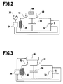
- FIG. 2 shows a schematic circuit diagram of a first embodiment of the sensor device 10 according to the invention.
- the sensor device 10 includes a voltage limited current source 32 (e.g., a power supply) to which a detector 34 is connected. By means of the detector 34, the ferromagnetic particles 12 deposited in the region of the sensor surface 22 can be detected.
- the detector 34 may be e.g. a Fe resonance detector, an IDK, a Hall detector, a resistive detector or an optical detector.
- An optical or acoustic display means 36 is connected to the detector 34 for displaying a signal of the detector 34, which represents a measure of the amount of particles 12 deposited on the sensor surface 22.
- the display means 36 may continuously display the detector signal (e.g., as a pointer instrument) or only when a predetermined threshold threshold is exceeded (e.g., as an LED).
- the sensor device 10 further includes a capacitor 38 that can be charged by the current source 32 when a first switch 40 is closed.
- the capacitor 38 is discharged via the induction coil 30 when a second switch 42 is closed.
- the capacitor 38 has a sufficiently high capacity, depending on the type of induction coil 30, for example in the range of about 3 to about 10 F. Suitable for this example is a double-layer capacitor.
- a maximum magnetic field is induced by the coil 30 at the beginning, which is opposite and stronger than the magnetic field of the permanent magnet 24, ie this is initially overcompensated.
- the tension of the Capacitor 38 and the current in the coil 30 fall continuously in the further course of the discharge, so that the induced magnetic field inevitably passes through an area in which the magnetic field of the permanent magnet 24 is accurately compensated. In this case, the force of attraction acting on the particles 12 is released and the sensor surface 22 is cleaned of the particles 12.
- the entire discharge process of the capacitor 38 usually takes only a few seconds.
- the second switch 42 is opened, so that the induction coil 30 is de-energized during charging.
- the display means 36 continuously displays the signal of the detector 34 and / or signals the reaching of the threshold value.
- the user can briefly open the first switch 40 and close the second switch 42 by actuating a switching device 44, so that the sensor surface 22 is cleaned by the discharge of the capacitor 38 via the induction coil 30.
- the first switch 40 is closed again and the second switch 42 is opened, the capacitor 38 is recharged and particles 12 begin to accumulate on the sensor surface 22 again.
- the length of the periods between two required actuations of the switching device 44 are a measure of the particle load of the fluid 14th
- FIG. 3 shows a schematic circuit diagram of a second embodiment of the sensor device 10th
- a control unit 46 connected to the detector 34 is provided, by means of which the discharge of the capacitor 38 can be controlled in dependence on a signal of the detector 34.
- the control unit 46 thus replaces the manual operation of a switching device, so that the sensor device 10 are operated automatically over a longer period of time can.
- the first switch 40 is opened by the control unit 46 for a short time and the second switch 42 is closed.
- the discharge of the capacitor 38 via the induction coil 30 then takes place as described above.
- the lengths of the periods between two discharges of the capacitor 38 are detected and stored by the control unit 46 and are a measure of the particle load of the fluid 14. As these periods become shorter, the contamination of the fluid 14 has increased.
- a display means for the signal of the detector 34 is not required in this case, but may optionally be provided.
Landscapes
- Chemical & Material Sciences (AREA)
- Physics & Mathematics (AREA)
- General Physics & Mathematics (AREA)
- Health & Medical Sciences (AREA)
- Life Sciences & Earth Sciences (AREA)
- Analytical Chemistry (AREA)
- Biochemistry (AREA)
- General Health & Medical Sciences (AREA)
- Engineering & Computer Science (AREA)
- Immunology (AREA)
- Pathology (AREA)
- Condensed Matter Physics & Semiconductors (AREA)
- Dispersion Chemistry (AREA)
- Chemical Kinetics & Catalysis (AREA)
- General Chemical & Material Sciences (AREA)
- Oil, Petroleum & Natural Gas (AREA)
- Food Science & Technology (AREA)
- Medicinal Chemistry (AREA)
- Investigating Or Analyzing Materials By The Use Of Magnetic Means (AREA)
Priority Applications (1)
| Application Number | Priority Date | Filing Date | Title |
|---|---|---|---|
| EP20100191838 EP2455774B1 (fr) | 2010-11-19 | 2010-11-19 | Dispositif de capteur et son procédé de fonctionnement |
Applications Claiming Priority (1)
| Application Number | Priority Date | Filing Date | Title |
|---|---|---|---|
| EP20100191838 EP2455774B1 (fr) | 2010-11-19 | 2010-11-19 | Dispositif de capteur et son procédé de fonctionnement |
Publications (2)
| Publication Number | Publication Date |
|---|---|
| EP2455774A1 true EP2455774A1 (fr) | 2012-05-23 |
| EP2455774B1 EP2455774B1 (fr) | 2013-08-21 |
Family
ID=43572044
Family Applications (1)
| Application Number | Title | Priority Date | Filing Date |
|---|---|---|---|
| EP20100191838 Active EP2455774B1 (fr) | 2010-11-19 | 2010-11-19 | Dispositif de capteur et son procédé de fonctionnement |
Country Status (1)
| Country | Link |
|---|---|
| EP (1) | EP2455774B1 (fr) |
Cited By (11)
| Publication number | Priority date | Publication date | Assignee | Title |
|---|---|---|---|---|
| BE1023946B1 (fr) * | 2016-03-14 | 2017-09-19 | Safran Aero Boosters Sa | Capteur de particules dans un fluide d'un systeme de lubrification |
| DE102017213224A1 (de) * | 2017-08-01 | 2019-02-07 | Zf Friedrichshafen Ag | Messanordnung zum Ermitteln eines ferromagnetischen Abriebes |
| CN110926999A (zh) * | 2019-12-12 | 2020-03-27 | 天津大学仁爱学院 | 一种机油铁磁性金属颗粒在线检测装置 |
| US10968795B2 (en) | 2019-04-09 | 2021-04-06 | Ford Global Technologies, Llc | Methods and systems for detection of particles in lubricant |
| WO2021104892A1 (fr) * | 2019-11-29 | 2021-06-03 | Safran Aero Boosters Sa | Systeme de detection de debris |
| BE1027807B1 (fr) * | 2019-11-29 | 2021-06-28 | Safran Aero Boosters Sa | Systeme de detection de debris |
| EP3888792A1 (fr) * | 2020-03-30 | 2021-10-06 | Safran Aero Boosters SA | Module d'attraction et de detection de debris |
| CN114295526A (zh) * | 2021-12-31 | 2022-04-08 | 哈尔滨工程大学 | 一种旁路油液磨粒监测捕捉装置 |
| WO2022233818A1 (fr) * | 2021-05-06 | 2022-11-10 | Safran Aero Boosters Sa | Module d'attraction et de detection de debris |
| DE102021117119A1 (de) | 2021-07-02 | 2023-01-05 | Inmox Gmbh | Sensoreinrichtung und Verfahren zur Charakterisierung eines Metallspans |
| US11609173B2 (en) * | 2017-07-27 | 2023-03-21 | Nederlandse Organisatie Voor Toegepast-Natuurwetenschappelijk Onderzoek Tno | Particle detection device and a method for detecting airborne particles |
Families Citing this family (2)
| Publication number | Priority date | Publication date | Assignee | Title |
|---|---|---|---|---|
| CN105043939A (zh) * | 2015-06-29 | 2015-11-11 | 广州机械科学研究院有限公司 | 获取磨粒图像信息时磨粒吸附及释放装置和方法 |
| RU2758746C1 (ru) * | 2021-03-11 | 2021-11-01 | Федеральное государственное бюджетное образовательное учреждение высшего образования «Тамбовский государственный технический университет» (ФГБОУ ВО «ТГТУ») | Способ оперативного контроля качества трансмиссионного масла |
Citations (3)
| Publication number | Priority date | Publication date | Assignee | Title |
|---|---|---|---|---|
| GB2029580A (en) | 1978-08-10 | 1980-03-19 | Central Electr Generat Board | Devices for detecting ferromagnetic particles in a liquid |
| US5674401A (en) * | 1991-12-11 | 1997-10-07 | Computational Systems, Inc. | Oil monitor with magnetic field |
| DE10339905A1 (de) * | 2003-08-29 | 2005-03-31 | Kist-Europe Forschungsgesellschaft Mbh | Implantierbarer Mikrozellprozessor zur Krankheitsbehandlung |
-
2010
- 2010-11-19 EP EP20100191838 patent/EP2455774B1/fr active Active
Patent Citations (3)
| Publication number | Priority date | Publication date | Assignee | Title |
|---|---|---|---|---|
| GB2029580A (en) | 1978-08-10 | 1980-03-19 | Central Electr Generat Board | Devices for detecting ferromagnetic particles in a liquid |
| US5674401A (en) * | 1991-12-11 | 1997-10-07 | Computational Systems, Inc. | Oil monitor with magnetic field |
| DE10339905A1 (de) * | 2003-08-29 | 2005-03-31 | Kist-Europe Forschungsgesellschaft Mbh | Implantierbarer Mikrozellprozessor zur Krankheitsbehandlung |
Cited By (18)
| Publication number | Priority date | Publication date | Assignee | Title |
|---|---|---|---|---|
| EP3220168A1 (fr) * | 2016-03-14 | 2017-09-20 | Safran Aero Booster S.A. | Capteur de particules dans un fluide d'un système de lubrification |
| WO2017157855A1 (fr) * | 2016-03-14 | 2017-09-21 | Safran Aero Boosters S.A. | Capteur de particules dans un fluide d'un système de lubrification |
| BE1023946B1 (fr) * | 2016-03-14 | 2017-09-19 | Safran Aero Boosters Sa | Capteur de particules dans un fluide d'un systeme de lubrification |
| US11609173B2 (en) * | 2017-07-27 | 2023-03-21 | Nederlandse Organisatie Voor Toegepast-Natuurwetenschappelijk Onderzoek Tno | Particle detection device and a method for detecting airborne particles |
| DE102017213224A1 (de) * | 2017-08-01 | 2019-02-07 | Zf Friedrichshafen Ag | Messanordnung zum Ermitteln eines ferromagnetischen Abriebes |
| US10968795B2 (en) | 2019-04-09 | 2021-04-06 | Ford Global Technologies, Llc | Methods and systems for detection of particles in lubricant |
| WO2021104892A1 (fr) * | 2019-11-29 | 2021-06-03 | Safran Aero Boosters Sa | Systeme de detection de debris |
| BE1027807B1 (fr) * | 2019-11-29 | 2021-06-28 | Safran Aero Boosters Sa | Systeme de detection de debris |
| CN110926999B (zh) * | 2019-12-12 | 2022-04-05 | 天津大学仁爱学院 | 一种机油铁磁性金属颗粒在线检测装置 |
| CN110926999A (zh) * | 2019-12-12 | 2020-03-27 | 天津大学仁爱学院 | 一种机油铁磁性金属颗粒在线检测装置 |
| EP3888792A1 (fr) * | 2020-03-30 | 2021-10-06 | Safran Aero Boosters SA | Module d'attraction et de detection de debris |
| BE1028174B1 (fr) * | 2020-03-30 | 2021-10-25 | Safran Aero Boosters | Module d’attraction et de detection de debris |
| WO2022233818A1 (fr) * | 2021-05-06 | 2022-11-10 | Safran Aero Boosters Sa | Module d'attraction et de detection de debris |
| BE1029383B1 (fr) * | 2021-05-06 | 2022-12-05 | Safran Aero Boosters | Module d'attraction et de detection de debris |
| DE102021117119A1 (de) | 2021-07-02 | 2023-01-05 | Inmox Gmbh | Sensoreinrichtung und Verfahren zur Charakterisierung eines Metallspans |
| WO2023275372A1 (fr) | 2021-07-02 | 2023-01-05 | Inmox Gmbh | Dispositif de détection et procédé de caractérisation d'un copeau de métal |
| CN114295526A (zh) * | 2021-12-31 | 2022-04-08 | 哈尔滨工程大学 | 一种旁路油液磨粒监测捕捉装置 |
| CN114295526B (zh) * | 2021-12-31 | 2024-04-12 | 哈尔滨工程大学 | 一种旁路油液磨粒监测捕捉装置 |
Also Published As
| Publication number | Publication date |
|---|---|
| EP2455774B1 (fr) | 2013-08-21 |
Similar Documents
| Publication | Publication Date | Title |
|---|---|---|
| EP2455774B1 (fr) | Dispositif de capteur et son procédé de fonctionnement | |
| EP1979733B1 (fr) | Dispositif de détection de particules dans un courant de fluide et système correspondant pour refroidir et/ou lubrifier | |
| DE4142996A1 (de) | Verfahren zum messen der mechanischen bewegung eines magnetventilankers, insbesondere von elektrisch gesteuerten einspritzanlagen | |
| DE102012002013A1 (de) | Prüfung einer Messgerätanordnung, entsprechende Messgerätanordnung und Prüfanordnung | |
| DE102011117295A1 (de) | Verfahren zur Erkennung von Störungen und zur Erfassung des Ventilhubs eines Leimventils | |
| EP1165944A1 (fr) | Procede permettant de determiner la position d'un induit | |
| EP1720179B1 (fr) | Ensemble magnétique ayant un dispositif pour reduire les pics de tension d'un alimentation et methode d'operation d'un tel ensemble | |
| EP0917644A1 (fr) | Appareil magneto-inductif de mesure du debit de milieux en ecoulement | |
| DE102008058185A1 (de) | Werkzeugspannvorrichtung | |
| DE10230759A1 (de) | Verfahren und Einrichtung zur Maschinendiagnose und insbesondere zur Getriebediagnose | |
| EP2217893B1 (fr) | Dispositif de détermination et/ou de surveillance d'un paramètre de procédé | |
| EP2492641A2 (fr) | Dispositif de mesure de trajectoire inductif | |
| DE102013212696A1 (de) | Vorrichtung zum Erfassen von metallischen ferromagnetischen Partikeln in einem Fluid | |
| EP3884359A1 (fr) | Procédé et dispositif de commande d'un aimant à tirant | |
| DE102017204304B4 (de) | Vorrichtung zur Messung der Menge von metallischen Teilchen in einer Flüssigkeit | |
| EP0900363B1 (fr) | Procede de commande d'un detecteur numerique et detecteur numerique correspondant | |
| DE202016100925U1 (de) | Vorrichtung zur Erkennung eines elektrisch leitfähigen Fremdkörpers | |
| DE3802121A1 (de) | Verfahren und vorrichtung zur bestimmung der muenzstapelhoehe in spielgeraeten | |
| DE10139243B4 (de) | Verfahren zur Überwachung eines elektromagnetisch betriebenen Aktors sowie elektromagnetisch betriebene Kupplung oder Bremse | |
| DE102014112452A1 (de) | Explosionsschutzschaltung mit Impedanzanpassung | |
| EP2844959B1 (fr) | Dispositif et procédé de mesure de la vitesse d'écoulement d'un fluide | |
| EP2992337B1 (fr) | Procédé et dispositif pour la surveillance et la mesure de courant d'une bobine soumise à une précontrainte magnétique | |
| EP3624341A1 (fr) | Émetteur d'impulsions | |
| DE102023108386B3 (de) | Teilentladungssensor, Verfahren zum Steuern eines Spalts eines Magnetkerns und Steuerungsvorrichtung | |
| WO2010108805A2 (fr) | Dispositif magnéto-inductif de mesure du débit, ainsi que procédé de fonctionnement de celui-ci |
Legal Events
| Date | Code | Title | Description |
|---|---|---|---|
| PUAI | Public reference made under article 153(3) epc to a published international application that has entered the european phase |
Free format text: ORIGINAL CODE: 0009012 |
|
| AK | Designated contracting states |
Kind code of ref document: A1 Designated state(s): AL AT BE BG CH CY CZ DE DK EE ES FI FR GB GR HR HU IE IS IT LI LT LU LV MC MK MT NL NO PL PT RO RS SE SI SK SM TR |
|
| AX | Request for extension of the european patent |
Extension state: BA ME |
|
| 17P | Request for examination filed |
Effective date: 20121123 |
|
| GRAP | Despatch of communication of intention to grant a patent |
Free format text: ORIGINAL CODE: EPIDOSNIGR1 |
|
| RIC1 | Information provided on ipc code assigned before grant |
Ipc: G01N 33/28 20060101ALI20130215BHEP Ipc: G01R 33/12 20060101AFI20130215BHEP Ipc: G01N 15/06 20060101ALI20130215BHEP |
|
| GRAS | Grant fee paid |
Free format text: ORIGINAL CODE: EPIDOSNIGR3 |
|
| GRAA | (expected) grant |
Free format text: ORIGINAL CODE: 0009210 |
|
| AK | Designated contracting states |
Kind code of ref document: B1 Designated state(s): AL AT BE BG CH CY CZ DE DK EE ES FI FR GB GR HR HU IE IS IT LI LT LU LV MC MK MT NL NO PL PT RO RS SE SI SK SM TR |
|
| REG | Reference to a national code |
Ref country code: GB Ref legal event code: FG4D Free format text: NOT ENGLISH |
|
| REG | Reference to a national code |
Ref country code: CH Ref legal event code: EP |
|
| REG | Reference to a national code |
Ref country code: AT Ref legal event code: REF Ref document number: 628396 Country of ref document: AT Kind code of ref document: T Effective date: 20130915 |
|
| REG | Reference to a national code |
Ref country code: IE Ref legal event code: FG4D Free format text: LANGUAGE OF EP DOCUMENT: GERMAN |
|
| REG | Reference to a national code |
Ref country code: SE Ref legal event code: TRGR |
|
| REG | Reference to a national code |
Ref country code: DE Ref legal event code: R096 Ref document number: 502010004435 Country of ref document: DE Effective date: 20131017 |
|
| REG | Reference to a national code |
Ref country code: NL Ref legal event code: VDEP Effective date: 20130821 |
|
| REG | Reference to a national code |
Ref country code: LT Ref legal event code: MG4D |
|
| PG25 | Lapsed in a contracting state [announced via postgrant information from national office to epo] |
Ref country code: IS Free format text: LAPSE BECAUSE OF FAILURE TO SUBMIT A TRANSLATION OF THE DESCRIPTION OR TO PAY THE FEE WITHIN THE PRESCRIBED TIME-LIMIT Effective date: 20131221 Ref country code: PT Free format text: LAPSE BECAUSE OF FAILURE TO SUBMIT A TRANSLATION OF THE DESCRIPTION OR TO PAY THE FEE WITHIN THE PRESCRIBED TIME-LIMIT Effective date: 20131223 Ref country code: NO Free format text: LAPSE BECAUSE OF FAILURE TO SUBMIT A TRANSLATION OF THE DESCRIPTION OR TO PAY THE FEE WITHIN THE PRESCRIBED TIME-LIMIT Effective date: 20131121 Ref country code: HR Free format text: LAPSE BECAUSE OF FAILURE TO SUBMIT A TRANSLATION OF THE DESCRIPTION OR TO PAY THE FEE WITHIN THE PRESCRIBED TIME-LIMIT Effective date: 20130821 Ref country code: CY Free format text: LAPSE BECAUSE OF FAILURE TO SUBMIT A TRANSLATION OF THE DESCRIPTION OR TO PAY THE FEE WITHIN THE PRESCRIBED TIME-LIMIT Effective date: 20130828 Ref country code: LT Free format text: LAPSE BECAUSE OF FAILURE TO SUBMIT A TRANSLATION OF THE DESCRIPTION OR TO PAY THE FEE WITHIN THE PRESCRIBED TIME-LIMIT Effective date: 20130821 |
|
| PG25 | Lapsed in a contracting state [announced via postgrant information from national office to epo] |
Ref country code: GR Free format text: LAPSE BECAUSE OF FAILURE TO SUBMIT A TRANSLATION OF THE DESCRIPTION OR TO PAY THE FEE WITHIN THE PRESCRIBED TIME-LIMIT Effective date: 20131122 Ref country code: PL Free format text: LAPSE BECAUSE OF FAILURE TO SUBMIT A TRANSLATION OF THE DESCRIPTION OR TO PAY THE FEE WITHIN THE PRESCRIBED TIME-LIMIT Effective date: 20130821 Ref country code: FI Free format text: LAPSE BECAUSE OF FAILURE TO SUBMIT A TRANSLATION OF THE DESCRIPTION OR TO PAY THE FEE WITHIN THE PRESCRIBED TIME-LIMIT Effective date: 20130821 Ref country code: SI Free format text: LAPSE BECAUSE OF FAILURE TO SUBMIT A TRANSLATION OF THE DESCRIPTION OR TO PAY THE FEE WITHIN THE PRESCRIBED TIME-LIMIT Effective date: 20130821 Ref country code: LV Free format text: LAPSE BECAUSE OF FAILURE TO SUBMIT A TRANSLATION OF THE DESCRIPTION OR TO PAY THE FEE WITHIN THE PRESCRIBED TIME-LIMIT Effective date: 20130821 |
|
| RAP2 | Party data changed (patent owner data changed or rights of a patent transferred) |
Owner name: FSP FLUID SYSTEMS PARTNERS HOLDING AG |
|
| PG25 | Lapsed in a contracting state [announced via postgrant information from national office to epo] |
Ref country code: CY Free format text: LAPSE BECAUSE OF FAILURE TO SUBMIT A TRANSLATION OF THE DESCRIPTION OR TO PAY THE FEE WITHIN THE PRESCRIBED TIME-LIMIT Effective date: 20130821 |
|
| PG25 | Lapsed in a contracting state [announced via postgrant information from national office to epo] |
Ref country code: NL Free format text: LAPSE BECAUSE OF FAILURE TO SUBMIT A TRANSLATION OF THE DESCRIPTION OR TO PAY THE FEE WITHIN THE PRESCRIBED TIME-LIMIT Effective date: 20130821 Ref country code: EE Free format text: LAPSE BECAUSE OF FAILURE TO SUBMIT A TRANSLATION OF THE DESCRIPTION OR TO PAY THE FEE WITHIN THE PRESCRIBED TIME-LIMIT Effective date: 20130821 Ref country code: CZ Free format text: LAPSE BECAUSE OF FAILURE TO SUBMIT A TRANSLATION OF THE DESCRIPTION OR TO PAY THE FEE WITHIN THE PRESCRIBED TIME-LIMIT Effective date: 20130821 Ref country code: RO Free format text: LAPSE BECAUSE OF FAILURE TO SUBMIT A TRANSLATION OF THE DESCRIPTION OR TO PAY THE FEE WITHIN THE PRESCRIBED TIME-LIMIT Effective date: 20130821 Ref country code: SK Free format text: LAPSE BECAUSE OF FAILURE TO SUBMIT A TRANSLATION OF THE DESCRIPTION OR TO PAY THE FEE WITHIN THE PRESCRIBED TIME-LIMIT Effective date: 20130821 Ref country code: DK Free format text: LAPSE BECAUSE OF FAILURE TO SUBMIT A TRANSLATION OF THE DESCRIPTION OR TO PAY THE FEE WITHIN THE PRESCRIBED TIME-LIMIT Effective date: 20130821 |
|
| PG25 | Lapsed in a contracting state [announced via postgrant information from national office to epo] |
Ref country code: ES Free format text: LAPSE BECAUSE OF FAILURE TO SUBMIT A TRANSLATION OF THE DESCRIPTION OR TO PAY THE FEE WITHIN THE PRESCRIBED TIME-LIMIT Effective date: 20130821 |
|
| BERE | Be: lapsed |
Owner name: ARGO-HYTOS G.M.B.H. Effective date: 20131130 |
|
| PLBE | No opposition filed within time limit |
Free format text: ORIGINAL CODE: 0009261 |
|
| STAA | Information on the status of an ep patent application or granted ep patent |
Free format text: STATUS: NO OPPOSITION FILED WITHIN TIME LIMIT |
|
| 26N | No opposition filed |
Effective date: 20140522 |
|
| PG25 | Lapsed in a contracting state [announced via postgrant information from national office to epo] |
Ref country code: MC Free format text: LAPSE BECAUSE OF FAILURE TO SUBMIT A TRANSLATION OF THE DESCRIPTION OR TO PAY THE FEE WITHIN THE PRESCRIBED TIME-LIMIT Effective date: 20130821 |
|
| REG | Reference to a national code |
Ref country code: IE Ref legal event code: MM4A |
|
| REG | Reference to a national code |
Ref country code: DE Ref legal event code: R097 Ref document number: 502010004435 Country of ref document: DE Effective date: 20140522 |
|
| PG25 | Lapsed in a contracting state [announced via postgrant information from national office to epo] |
Ref country code: BE Free format text: LAPSE BECAUSE OF NON-PAYMENT OF DUE FEES Effective date: 20131130 |
|
| PG25 | Lapsed in a contracting state [announced via postgrant information from national office to epo] |
Ref country code: IE Free format text: LAPSE BECAUSE OF NON-PAYMENT OF DUE FEES Effective date: 20131119 |
|
| PGFP | Annual fee paid to national office [announced via postgrant information from national office to epo] |
Ref country code: SE Payment date: 20141111 Year of fee payment: 5 |
|
| PG25 | Lapsed in a contracting state [announced via postgrant information from national office to epo] |
Ref country code: SM Free format text: LAPSE BECAUSE OF FAILURE TO SUBMIT A TRANSLATION OF THE DESCRIPTION OR TO PAY THE FEE WITHIN THE PRESCRIBED TIME-LIMIT Effective date: 20130821 |
|
| PG25 | Lapsed in a contracting state [announced via postgrant information from national office to epo] |
Ref country code: TR Free format text: LAPSE BECAUSE OF FAILURE TO SUBMIT A TRANSLATION OF THE DESCRIPTION OR TO PAY THE FEE WITHIN THE PRESCRIBED TIME-LIMIT Effective date: 20130821 |
|
| REG | Reference to a national code |
Ref country code: CH Ref legal event code: PL |
|
| REG | Reference to a national code |
Ref country code: DE Ref legal event code: R082 Ref document number: 502010004435 Country of ref document: DE Representative=s name: HOEGER, STELLRECHT & PARTNER PATENTANWAELTE MB, DE |
|
| PG25 | Lapsed in a contracting state [announced via postgrant information from national office to epo] |
Ref country code: LI Free format text: LAPSE BECAUSE OF NON-PAYMENT OF DUE FEES Effective date: 20141130 Ref country code: BG Free format text: LAPSE BECAUSE OF FAILURE TO SUBMIT A TRANSLATION OF THE DESCRIPTION OR TO PAY THE FEE WITHIN THE PRESCRIBED TIME-LIMIT Effective date: 20130821 Ref country code: RS Free format text: LAPSE BECAUSE OF FAILURE TO SUBMIT A TRANSLATION OF THE DESCRIPTION OR TO PAY THE FEE WITHIN THE PRESCRIBED TIME-LIMIT Effective date: 20131121 Ref country code: HU Free format text: LAPSE BECAUSE OF FAILURE TO SUBMIT A TRANSLATION OF THE DESCRIPTION OR TO PAY THE FEE WITHIN THE PRESCRIBED TIME-LIMIT; INVALID AB INITIO Effective date: 20101119 Ref country code: MK Free format text: LAPSE BECAUSE OF FAILURE TO SUBMIT A TRANSLATION OF THE DESCRIPTION OR TO PAY THE FEE WITHIN THE PRESCRIBED TIME-LIMIT Effective date: 20130821 Ref country code: LU Free format text: LAPSE BECAUSE OF NON-PAYMENT OF DUE FEES Effective date: 20131119 Ref country code: CH Free format text: LAPSE BECAUSE OF NON-PAYMENT OF DUE FEES Effective date: 20141130 |
|
| PG25 | Lapsed in a contracting state [announced via postgrant information from national office to epo] |
Ref country code: MT Free format text: LAPSE BECAUSE OF FAILURE TO SUBMIT A TRANSLATION OF THE DESCRIPTION OR TO PAY THE FEE WITHIN THE PRESCRIBED TIME-LIMIT Effective date: 20130821 |
|
| REG | Reference to a national code |
Ref country code: FR Ref legal event code: PLFP Year of fee payment: 6 |
|
| PG25 | Lapsed in a contracting state [announced via postgrant information from national office to epo] |
Ref country code: SE Free format text: LAPSE BECAUSE OF NON-PAYMENT OF DUE FEES Effective date: 20151120 |
|
| REG | Reference to a national code |
Ref country code: FR Ref legal event code: PLFP Year of fee payment: 7 |
|
| REG | Reference to a national code |
Ref country code: AT Ref legal event code: MM01 Ref document number: 628396 Country of ref document: AT Kind code of ref document: T Effective date: 20151119 |
|
| PG25 | Lapsed in a contracting state [announced via postgrant information from national office to epo] |
Ref country code: AT Free format text: LAPSE BECAUSE OF NON-PAYMENT OF DUE FEES Effective date: 20151119 |
|
| REG | Reference to a national code |
Ref country code: FR Ref legal event code: PLFP Year of fee payment: 8 |
|
| REG | Reference to a national code |
Ref country code: FR Ref legal event code: PLFP Year of fee payment: 9 |
|
| PG25 | Lapsed in a contracting state [announced via postgrant information from national office to epo] |
Ref country code: AL Free format text: LAPSE BECAUSE OF FAILURE TO SUBMIT A TRANSLATION OF THE DESCRIPTION OR TO PAY THE FEE WITHIN THE PRESCRIBED TIME-LIMIT Effective date: 20130821 |
|
| PGFP | Annual fee paid to national office [announced via postgrant information from national office to epo] |
Ref country code: FR Payment date: 20181011 Year of fee payment: 9 Ref country code: IT Payment date: 20181122 Year of fee payment: 9 Ref country code: GB Payment date: 20181114 Year of fee payment: 9 |
|
| REG | Reference to a national code |
Ref country code: DE Ref legal event code: R082 Ref document number: 502010004435 Country of ref document: DE Representative=s name: HOEGER, STELLRECHT & PARTNER PATENTANWAELTE MB, DE |
|
| REG | Reference to a national code |
Ref country code: DE Ref legal event code: R082 Ref document number: 502010004435 Country of ref document: DE Representative=s name: HOEGER, STELLRECHT & PARTNER PATENTANWAELTE MB, DE Ref country code: DE Ref legal event code: R081 Ref document number: 502010004435 Country of ref document: DE Owner name: FSP FLUID SYSTEMS PARTNERS HOLDING AG, CH Free format text: FORMER OWNER: ARGO-HYTOS GMBH, 76703 KRAICHTAL, DE Ref country code: DE Ref legal event code: R081 Ref document number: 502010004435 Country of ref document: DE Owner name: ARGO-HYTOS GROUP AG, CH Free format text: FORMER OWNER: ARGO-HYTOS GMBH, 76703 KRAICHTAL, DE |
|
| GBPC | Gb: european patent ceased through non-payment of renewal fee |
Effective date: 20191119 |
|
| PG25 | Lapsed in a contracting state [announced via postgrant information from national office to epo] |
Ref country code: FR Free format text: LAPSE BECAUSE OF NON-PAYMENT OF DUE FEES Effective date: 20191130 Ref country code: GB Free format text: LAPSE BECAUSE OF NON-PAYMENT OF DUE FEES Effective date: 20191119 Ref country code: IT Free format text: LAPSE BECAUSE OF NON-PAYMENT OF DUE FEES Effective date: 20191119 |
|
| REG | Reference to a national code |
Ref country code: DE Ref legal event code: R082 Ref document number: 502010004435 Country of ref document: DE Representative=s name: HOEGER, STELLRECHT & PARTNER PATENTANWAELTE MB, DE Ref country code: DE Ref legal event code: R081 Ref document number: 502010004435 Country of ref document: DE Owner name: ARGO-HYTOS GROUP AG, CH Free format text: FORMER OWNER: FSP FLUID SYSTEMS PARTNERS HOLDING AG, BAAR, CH |
|
| PGFP | Annual fee paid to national office [announced via postgrant information from national office to epo] |
Ref country code: DE Payment date: 20231121 Year of fee payment: 14 |