EP2454926B1 - Gehäuse für eine elektronische vorrichtung - Google Patents
Gehäuse für eine elektronische vorrichtung Download PDFInfo
- Publication number
- EP2454926B1 EP2454926B1 EP10729802.8A EP10729802A EP2454926B1 EP 2454926 B1 EP2454926 B1 EP 2454926B1 EP 10729802 A EP10729802 A EP 10729802A EP 2454926 B1 EP2454926 B1 EP 2454926B1
- Authority
- EP
- European Patent Office
- Prior art keywords
- parts
- housing
- housing according
- interior
- projection
- Prior art date
- Legal status (The legal status is an assumption and is not a legal conclusion. Google has not performed a legal analysis and makes no representation as to the accuracy of the status listed.)
- Active
Links
Images






Classifications
-
- H—ELECTRICITY
- H05—ELECTRIC TECHNIQUES NOT OTHERWISE PROVIDED FOR
- H05K—PRINTED CIRCUITS; CASINGS OR CONSTRUCTIONAL DETAILS OF ELECTRIC APPARATUS; MANUFACTURE OF ASSEMBLAGES OF ELECTRICAL COMPONENTS
- H05K7/00—Constructional details common to different types of electric apparatus
- H05K7/20—Modifications to facilitate cooling, ventilating, or heating
- H05K7/2089—Modifications to facilitate cooling, ventilating, or heating for power electronics, e.g. for inverters for controlling motor
- H05K7/209—Heat transfer by conduction from internal heat source to heat radiating structure
-
- H—ELECTRICITY
- H05—ELECTRIC TECHNIQUES NOT OTHERWISE PROVIDED FOR
- H05K—PRINTED CIRCUITS; CASINGS OR CONSTRUCTIONAL DETAILS OF ELECTRIC APPARATUS; MANUFACTURE OF ASSEMBLAGES OF ELECTRICAL COMPONENTS
- H05K7/00—Constructional details common to different types of electric apparatus
- H05K7/14—Mounting supporting structure in casing or on frame or rack
- H05K7/1422—Printed circuit boards receptacles, e.g. stacked structures, electronic circuit modules or box like frames
- H05K7/1427—Housings
- H05K7/1432—Housings specially adapted for power drive units or power converters
- H05K7/14322—Housings specially adapted for power drive units or power converters wherein the control and power circuits of a power converter are arranged within the same casing
-
- H—ELECTRICITY
- H05—ELECTRIC TECHNIQUES NOT OTHERWISE PROVIDED FOR
- H05K—PRINTED CIRCUITS; CASINGS OR CONSTRUCTIONAL DETAILS OF ELECTRIC APPARATUS; MANUFACTURE OF ASSEMBLAGES OF ELECTRICAL COMPONENTS
- H05K7/00—Constructional details common to different types of electric apparatus
- H05K7/14—Mounting supporting structure in casing or on frame or rack
- H05K7/1422—Printed circuit boards receptacles, e.g. stacked structures, electronic circuit modules or box like frames
- H05K7/1427—Housings
- H05K7/1432—Housings specially adapted for power drive units or power converters
- H05K7/14327—Housings specially adapted for power drive units or power converters having supplementary functional units, e.g. data transfer modules or displays or user interfaces
-
- H—ELECTRICITY
- H05—ELECTRIC TECHNIQUES NOT OTHERWISE PROVIDED FOR
- H05K—PRINTED CIRCUITS; CASINGS OR CONSTRUCTIONAL DETAILS OF ELECTRIC APPARATUS; MANUFACTURE OF ASSEMBLAGES OF ELECTRICAL COMPONENTS
- H05K7/00—Constructional details common to different types of electric apparatus
- H05K7/20—Modifications to facilitate cooling, ventilating, or heating
- H05K7/2039—Modifications to facilitate cooling, ventilating, or heating characterised by the heat transfer by conduction from the heat generating element to a dissipating body
- H05K7/20518—Unevenly distributed heat load, e.g. different sectors at different temperatures, localised cooling, hot spots
Definitions
- the invention relates to a housing.
- the invention is therefore based on the object of making a housing more flexible, safer and easier to assemble.
- the object is achieved in the housing according to the features specified in claim 1.
- the housing enclosing an interior comprises housing parts and a base designed as a heat sink, several molded parts in the interior of the housing together with the base electrically and thermally delimiting a plurality of spatial areas from one another and from the rest of the interior.
- the advantage here is that the individual room areas and the rest of the interior can be better used, since electrical and thermal influences are reduced.
- the base is constructed modularly from one or more base parts and the one or more molded parts in the interior of the housing at least partially cover or cover the base part or the several base parts.
- the advantage here is that the floor parts can be preassembled.
- At least one molded part is a stamped part folded in such a way that a hood-like shape is formed.
- the advantage here is that the molded part is easy to manufacture and easy to store.
- At least one molded part is produced in a plastic deep-drawing process in such a way that a hood-like shape is formed.
- the advantage here is that the molded part can be easily produced in complex shapes.
- At least one molded part is made from a thermoplastic, in particular polypropylene, preferably a flame-retardant polypropylene.
- a thermoplastic in particular polypropylene, preferably a flame-retardant polypropylene.
- the polypropylene has a dielectric strength of 19.7 to 106 kV / mm (500 to 2700 volts / mil), in particular 39.4 to 78.7 kV / mm (1000 to 2000 volts / mil).
- the advantage here is that the room areas are well electrically isolated from each other.
- the base or the base part, has cooling fins on an outside of the housing.
- each of the molded parts covers a structural unit of the electronic device.
- a separate molded part covers each structural unit of the electronic device.
- the shape of the molded part follows an imaginary, tight-fitting envelope of the structural unit.
- the advantage here is that the interior is easy to use.
- the structural unit has heat-generating components which are arranged on a printed circuit board, the heat-generating components being thermally conductively connected to the floor, in particular via a structure with a thermal conductivity of greater than 2.5 W / (mK).
- the advantages here is that the components are well heated without thermally stressing the rest of the interior or other room area.
- the molded part has a hole which is used to carry out a fastening means for fastening the molded part to the base part.
- the housing parts comprise a cover, walls and corner parts, the corner parts connecting the walls and the cover being connected to the floor via the walls and / or the corner parts.
- the base part or the plurality of base parts have a substantially rectangular shape, two opposite edges of the base part or the plurality of base parts being designed as a groove or a nose, the groove and the nose of two base parts arranged next to one another in one another to grab.
- the advantage here is that the floor parts can be assembled safely and easily.
- the base is closed at the edges of the base part or the plurality of base parts, which are designed as a groove or nose, each with an appropriately designed end piece, the corresponding end piece having either a groove or a nose and that of the groove or the edge of the end piece opposite the nose is flat.
- two adjacent base parts are connected, in particular screwed, by an additional connecting element, the connecting element preferably being electrically and / or thermally conductive.
- the connecting element preferably being electrically and / or thermally conductive.
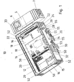
- the Figure 1 shows a housing 10 according to the invention for a converter for controlling an electric motor.
- the housing 10 according to the invention comprises a base 14, walls 50 and corner parts 52.
- the base 14 is composed of individual base parts 20.
- the housing parts, and in particular the cover, can also be used as expanding cooling surfaces due to the corresponding design with an enlarged surface.
- the housing 10 encloses an approximately cuboid interior 12.
- Three molded parts 16 are arranged in the interior 12 of the housing 10.
- One of the molded parts 16 is designed as a folded stamped part 22.
- the other molded part 16 is produced as a deep-drawn part 17 by a plastic deep-drawing process.
- a third molded part 16 is designed as a sheet metal part 15.
- the sheet metal part 15 can be produced by folding or deep drawing.
- Metal, coated metal, plastic, tempered glass, PU foam or similar materials are also conceivable as further materials for producing the molded parts 16.
- the molded parts 16 are arranged in the interior 12 such that in each case one space area 18 of the interior space 12 is electrically and thermally delimited by the other space areas 18 and the rest of the interior space.
- Electronic devices are arranged in the room areas 18.
- the electronic devices are fastened to the base parts 20 and covered by the molded parts 16. Connection elements for the electronic device look out of the respective room area 18.
- Additional electronic devices can be installed in the interior 12 between the cover (not shown) and the molded parts 16.
- 16 power modules of the converter such as rectifiers, intermediate circuit capacitors and inverters for controlling a motor, are arranged under the molded parts.
- the further electronic devices such as control electronics for evaluating and processing control signals from a higher-level control and control electronics for the inverter, are installed in the housing 10 in the further interior.
- the base part 20 has a cuboid base. Cooling fins 30 of different shapes are molded onto the surface of the base parts 20 facing away from the interior 12.
- the base part 20 is preferably made in particular in one piece from aluminum. If the cooling capacity without cooling fins 30 is sufficient, base parts 20 without cooling fins can also be used.
- One of the walls 50 can optionally be replaced by a switching element 5 arranged outside the housing 10.
- the switching element 5 serves as a switch for the converter.
- the switching element 5 has a rotary switch 6 and cable bushings 7.
- the electrical components of auxiliary axes, power supplies, I / O extensions or similar control or drive elements can be installed or attached to one of the walls 50.
- a wall 50 of the housing 10 is designed as a terminal block 54 and has cable bushings with further plug connections 55.
- Control bus lines for example PROFIBUS, DeviceNet or Ethernet fieldbus or electric motor supply cables, can be connected to the further plug connections 55.
- Other of the further plug connections allow the connection of an external braking resistor or the connection of a speed sensor of the electric motor supplied by the converter.
- a bus module 53 can also be connected, with which the bus address of the converter can be set from the outside without opening the housing 10.
- FIG. 2 shows a top view of the stamped part 22.
- the stamped part 22 corresponds to a network of a molded part 16 to be folded Slots 36 a.
- the clamping tabs 24 have approximately the shape of isosceles trapezoids, which have recesses in the non-parallel side lines, so that a type of laterally protruding barbs 28 is formed at the narrow end of the isosceles trapezium. These barbs 28 hold the clamping tabs 24 in the slots 26.
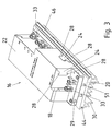
- the Figures 3 . 4 and 5 show the stamped part 22 in the folded state.
- the folded stamped part 22 has an almost cuboid shape.
- the folded stamped part 22 is mounted on a bottom part 20 of the housing according to the invention.
- a bottom section 23 of the stamped part 22 is screwed to the bottom part 20.
- the molded parts are clamped on the floor or fastened with clamping elements.
- the room area 18 is almost completely electrically and thermally insulated from its surroundings.
- the stamped part is made of a thermoplastic, in particular polypropylene, which has a dielectric strength of 19.7 to 106 kV / mm (500 to 2700 volts / mil). especially from 39.4 to 78.7 kV / mm (1000 to 2000 volts / mil).
- the thermoplastic is preferably flame retardant or self-extinguishing.
- the largest part of a printed circuit board 32 is arranged in the area 18.
- a rectifier module of the converter is preferably arranged on the printed circuit board 32.
- the circuit board 32 is screwed to the bottom part 20 on spacers 29.
- the spacers 29 are arranged over holes in the base section 23, so that the printed circuit board 32 and the stamped part 22 are screwed to the base part 20 with the same screws.
- the electronic components on the printed circuit board 32 are thus better thermally and electrically shielded.
- the thermal load on the surroundings of the printed circuit board by heat-generating components on the printed circuit board 32 is reduced or largely restricted to the area 18.
- Another advantage is the mechanical protection of the circuit board 32 and especially the electronic components. This allows a simplified assembly of the housing 10 constructed from the base parts 20 and the further housing parts.
- Molded parts made of metal or a material comprising metal offer the advantage of shielding against electromagnetic interference and thus improve the electromagnetic compatibility.
- Sensitive control electronics and power units can also be arranged in the housing 10.
- the bottom section 23 optionally has an opening 25. Through this opening 25, heat-generating components which are mounted on the printed circuit board 32 are thermally connected to the base part 20 via a heat-conducting structure.
- Connection sections of the circuit board 32 look out of the space area 18.
- Means for electrical connection preferably as a clamping device 33, are arranged on these connecting sections. Line elements for electrical power and / or signal transmission can be connected to the clamping devices 33.
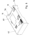
- the Figures 6 to 10 show a further embodiment of a molded part 16 according to the invention
- Figures 6 to 10 Shown part 16 is produced in a plastic deep-drawing process as a deep-drawn part 17.
- the deep-drawn part 17 has an approximately cuboid, hood-like shape and is made of a thermoplastic, in particular polypropylene, with an electrical dielectric strength between 19.7 to 106 kV / mm (500 to 2700 volts / mil).
- the deep-drawn part 17 has no bottom section.
- a room area 18 enclosed by the deep-drawn part 17 is delimited by the corresponding base part 20.
- Wall sections 19 between the side facing away from the base part 20 and the printed circuit board 32 or the base part 20 partially stand on the printed circuit board 32. Other sections of the walls extend down to the base part 20.
- the deep-drawn part 17 preferably covers the inverter for controlling a motor.
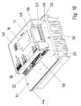
- a printed circuit board 32 is arranged in the space area 18 and is screwed to the base part 20. Electrical connection areas of the printed circuit board 32 protrude from the deep-drawn part 17. For this purpose, a wall of the deep-drawn part 17 is pulled inwards and thus forms a retracted wall 56. Electrical contact elements which are arranged on the electrical connection areas are thus accessible. In Figure 10 are shown on the retracted wall 56 as electrical contact elements cable lugs 57. Further contact elements look out from the deep-drawn part on one side. Contact elements of a plug-in card 58 also look out from this side. The position of the plug-in card 58 is in Figure 10 shown by a solid line that is actually not visible. The plug-in card 58 is detachably inserted in a corresponding holder on the printed circuit board 32.
- Figure 9 shows an intermediate wall 62 of the deep-drawn part 17.
- the intermediate wall 62 in cooperation with the electronic devices arranged under the deep-drawn part 17, the space area 18 can be subdivided further.
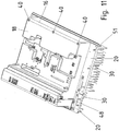
- Figure 11 shows a modified embodiment of the further embodiment of the molded part 16 for a housing according to the invention.
- Shaped part 16 shown has a more complex shape. The shape follows an imaginary envelope of the printed circuit board 32 arranged in the space area enclosed by the molded part 16 and two corresponding base parts 20. Electrical connection means protrude from the molded part 16. The shape makes electrical connection means for connecting electrical lines more accessible.
- the two base parts 20 are screwed together via a connecting element 48. This allows thermal compensation and electrical potential equalization.
- Holding elements 51 are shown with which the walls 50 or the switching element 5 can be fastened to the bottom 14 of the housing 10.
- the base part 20 or the plurality of base parts 20 essentially have a rectangular shape. Two edges of the base part 20 or the plurality of base parts 20 lying opposite one another in the assembled housing 10 are designed as a groove 44 or a nose 46. The groove 44 and the nose 46 of two base parts 20 arranged next to one another engage with one another. As a result, the base parts 20 are assembled safely and easily.
- the edges of the base 14 or the corresponding outer base parts 20 which are designed as a groove 44 or nose 46 are each completed with a correspondingly designed end piece, the corresponding end piece having either a groove 44 or a nose 46 and that of the groove 44 or Nose 46 opposite edge of the end piece is flat.
- the end pieces preferably have an external T-groove, with which the housing 10 can be easily assembled.
Landscapes
- Engineering & Computer Science (AREA)
- Microelectronics & Electronic Packaging (AREA)
- Physics & Mathematics (AREA)
- Thermal Sciences (AREA)
- Human Computer Interaction (AREA)
- Cooling Or The Like Of Electrical Apparatus (AREA)
- Casings For Electric Apparatus (AREA)
Description
- Die Erfindung betrifft ein Gehäuse.
- Aus der
EP 0 954 210 A1 ist eine Kühlanordnung für ein Elektronikgerät bekannt. - Aus der
EP 1 996 004 A1 ist ein Wechselrichtergehäuse bekannt. - Aus der
EP 1 467 406 A1 ist ein modular aufgebautes Leistungshalbleitermodul bekannt. - Aus der
DE 10 2004 034 834 A1 ist ein Baukasten von Gehäusen bekannt. - Der Erfindung liegt daher die Aufgabe zugrunde, ein Gehäuse flexibler, sicherer und einfacher montierbar auszuführen.
- Erfindungsgemaß wird die Aufgabe bei dem Gehäuse nach den in Anspruch 1 angegebenen Merkmalen gelöst.
- Wichtige Merkmale der Erfindung bei dem Gehäuse sind, dass das einen Innenraum umschließende Gehäuse Gehäuseteile und einen als Kühlkörper ausgebildeten Boden umfasst, wobei mehrere Formteile in dem Innenraum des Gehäuses zusammen mit dem Boden mehrere Raumbereiche untereinander und zum restlichen Innenraum elektrisch und thermisch begrenzen. Von Vorteil ist dabei, dass die einzelnen Raumbereiche und der restljche Innenraum besser nutzbar sind, da elektrische und thermische Beeinflussungen verringert sind.
- Bei einer vorteilhaften Ausgestaltung ist der Boden modular aus einem oder mehreren Bodenteilen aufgebaut und das eine oder die mehreren Formteile im Innenraum des Gehäuses das Bodenteil oder die mehreren Bodenteile zumindest teilweise abdeckt beziehungsweise abdecken. Von Vorteil ist dabei, dass die Bodenteile vormontierbar sind.
- Erfindungsgemäß ist mindestens ein Formteil ein derart gefaltetes Stanzteil, dass eine haubenartige Form gebildet ist. Von Vorteil ist dabei, dass das Formteil einfach herstellbar und einfach lagerbar ist.
- Erfindungsgemäß ist mindestens ein Formteil in einem Kunststofftiefziehprozess derart hergestellt, dass eine haubenartige Form gebildet ist. Von Vorteil ist dabei, dass das Formteil einfach in komplexen Formen herstellbar ist.
- Bei einer weiteren vorteilhaften Ausgestaltung ist mindestens ein Formteil aus einem Thermoplast, insbesondere Polypropylen, vorzugsweise einem flammhemmenden Polypropylen, hergesteilt. Von Vorteil ist dabei, dass das Formteil auch in komplizierten Formen einfach herstellbar ist.
- Bei einer weiteren vorteilhaften Ausgestaltung weist das Polypropylen eine Durchschlagsfestigkeit von 19,7 bis 106 kV/mm (500 bis 2700 Volt/mil) insbesondere von 39,4 bis 78,7 kV/mm (1000 bis 2000 Volt/mil), auf. Von Vorteil ist dabei, dass die Raumbereiche gut elektrische voneinander isoliert sind.
- Bei einer weiteren vorteilhaften Ausgestaltung weist der Boden, beziehungsweise das Bodenteil, Kühlrippen an einer Außenseite des Gehäuses auf. Von Vorteil ist dabei, dass elektronische Bauteile in den Raumbereichen gut kühlbar sind.
- Erfindungsgemäß deckt jedes der Formteile eine Baueinheit der elektronischen Vorrichtung ab. Bei einer weiteren vorteilhaften Ausgestaltung deckt je ein separates Formteil jede Baueinheit der elektronischen Vorrichtung ab. Von Vorteil ist dabei, dass das Gehäuse einfacher montierbar ist und die Raumbereiche auch vor allem bei der Montage und dem Versand mechanisch geschützt sind.
- Bei einer weiteren vorteilhaften Ausgestaltung folgt das Formteil mit seiner Form einer gedachten, enganliegenden Einhüllenden der Baueinheit. Von Vorteil ist dabei, dass der Innenraum gut ausnutzbar ist.
- Bei einer weiteren vorteilhaften Ausgestaltung weist die Baueinheit wärmeerzeugende Bauelemente auf, welche auf einer Leiterplatte angeordnet sind, wobei die wärmeerzeugenden Bauelemente mit dem Boden thermisch leitend verbunden sind, insbesondere über eine Struktur mit einer Wärmeleitfähigkeit von grösser als 2.5 W/(mK). Von Vorteil ist dabei, dass die Bauelemente gut entwärmt werden ohne den restlichen Innenraum oder andere Raumbereich thermisch zu belasten.
- Bei einer weiteren vorteilhaften Ausgestaltung weist das Formteil ein Loch auf, welches zum Durchführen eines Befestigungsmittels zum Befestigen des Formteils an dem Bodenteil dient. Von Vorteil ist dabei, dass das Formteil einfach am Bodenteil befestigbar ist.
- Bei einer weiteren vorteilhaften Ausgestaltung umfassen die Gehäuseteile einen Deckel, Wände und Eckteile, wobei die Eckteile die Wände verbinden und der Deckel über die Wände und/oder die Eckteile mit dem Boden verbunden sind. Von Vorteil ist dabei, dass das Gehäuse modular aufbaubar ist und somit einfach in verschiedenen Größen fertigbar ist.
- Bei einer weiteren vorteilhaften Ausgestaltung weisen das Bodenteil oder die mehreren Bodenteile im wesentlichen eine rechteckige Form auf, wobei zwei sich gegenüberliegende Kanten des Bodenteils oder der mehreren Bodenteile als eine Nut oder eine Nase ausgebildet sind, wobei die Nut und die Nase zweier nebeneinander angeordneter Bodenteile ineinander greifen. Von Vorteil ist dabei, dass die Bodenteile sicher und einfach zusammenfügbar sind.
- Bei einer weiteren vorteilhaften Ausgestaltung ist der Boden an den Kanten des Bodenteils bzw. der mehreren Bodenteile, welche als Nut oder Nase ausgebildet sind mit je einem entsprechend ausgeführten Endstück abgeschlossen, wobei das entsprechende Endstück entweder eine Nut oder eine Nase aufweist und die der Nut oder der Nase gegenüberliegende Kante des Endstücks eben ist. Von Vorteil ist dabei, dass das Gehäuse einfach modular montierbar ist.
- Bei einer weiteren vorteilhaften Ausgestaltung sind zwei benachbarte Bodenteile durch ein zusätzliches Verbindungselemente verbunden, insbesondere verschraubt, wobei das Verbindungselement vorzugsweise elektrische und/oder thermisch leitend ist. Von Vorteil ist dabei, dass die Bodenteile sicher und steif miteinander verbunden sind und ein definiertes gleiches elektrisches Potential gegenüber der auf Ihnen montierten Leiterplatte besitzen.
- Weitere Vorteile ergeben sich aus den Unteransprüchen.
- Die Erfindung wird nun anhand von Ausführungsbeispielen mit Bezugnahme auf die Zeichnung näher erläutert. Es zeigen rein schematisch:
- Fig. 1
- eine dreidimensionale Draufsicht eines erfindungsgemäßen Gehäuse
- Fig. 2
- ein Stanzteil für ein erfindungsgemäßes Gehäuse in ungefaltetem Zustand;
- Fig. 3
- eine Isometrie des in
Figur 1 gezeigten Stanzteils gefaltet und auf ein Bodenteil eines erfindungsgemäßen Gehäuses montiert; - Fig. 4
- das in
Figur 3 gezeigte Stanzteil in Draufsicht; - Fig. 5
- eine Seitenansicht des in
Figur 3 gezeigten Stanzteils; - Fig. 6
- eine Isometrie eines in einem Kunststofftiefziehprozess hergestellten Formteils;
- Fig. 7
- eine Draufsicht des in
Figur 6 gezeigten Formteils; - Fig. 8
- ein Längsschnitt durch das in
Figur 6 gezeigte Formteil; - Fig. 9
- ein Querschnitt durch das in
Figur 6 gezeigte Formteil; - Fig. 10
- das in
Figur 6 gezeigte Formteil auf ein Bodenteil montiert; und - Fig. 11
- eine weitere Ausführungsform eines Formteils in montiertem Zustand für ein erfindungsgemäßes Gehäuse.
- Die
Figur 1 zeigt ein erfindungsgemäßes Gehäuse 10 für einen Umrichter zur Ansteuerung eines Elektromotors. Das erfindungsgemäße Gehäuse 10 umfasst neben dem nicht gezeigten Deckel einen Boden 14, Wände 50 und Eckteile 52. Der Boden 14 ist aus einzelnen Bodenteilen 20 zusammengesetzt. Die Gehäuseteile und insbesondere der Deckel, sind auch durch entsprechende Formgestaltung mit vergrößerter Oberfläche als erweiternde Kühlflächen nutzbar. Das Gehäuse 10 umschließt einen annähernd quaderförmigen Innenraum 12. - Im Innenraum 12 des Gehäuses 10 sind drei Formteile 16 angeordnet. Eines der Formteile 16 ist als zusammengefaltetes Stanzteil 22 ausgeführt. Das andere Formteil 16 ist als Tiefziehteil 17 durch einen Kunststofftiefziehprozess hergestellt. Ein drittes Formteil 16 ist als Blechteil 15 ausgeführt. Das Blechteil 15 ist durch Falten oder Tiefziehen herstellbar. Als weitere Materialien zur Herstellung der Formteile 16 sind auch Metall, beschichtetes Metall, Kunststoff, getempertes Glas, PU-Schaum oder ähnliche Materialien denkbar.
- Die Formteile 16 sind so im Innenraum 12 angeordnet, dass jeweils ein Raumbereich 18 des Innenraums 12 von den anderen Raumbereichen 18 und dem restlichen Innenraum elektrisch und thermisch begrenzt ist.
- In den Raumbereichen 18 sind elektronische Vorrichtungen angeordnet. Die elektronischen Vorrichtungen sind an den Bodenteilen 20 befestigt und von den Formteilen 16 abgedeckt. Anschlusselemente für die elektronische Vorrichtung schauen aus dem jeweiligen Raumbereich 18 heraus.
- Andere elektronische Vorrichtungen sind auf weiteren Bodenteilen 20 angeordnet, welche nicht von einem Formteil abgedeckt sind.
- Zwischen dem nicht gezeigten Deckel und den Formteilen 16 lassen sich noch weitere elektronische Vorrichtungen im Innenraum 12 anbringen Zum Beispiel sind unter den Formteilen 16 Leistungsmodule des Umrichters, wie Gleichrichter, Zwischenkreiskondensatoren und Wechselrichter zur Ansteuerung eines Motors angeordnet. Im Weiteren Innenraum sind die weiteren elektronischen Vorrichtungen, wie zum Beispiel eine Steuerungselektronik zur Auswertung und Verarbeitung von Steuersignalen einer übergeordneten Steuerung und eine Ansteuerungselektronik für den Wechselrichter im Gehäuse 10 eingebaut.
- Das Bodenteil 20 weist einen quaderförmigen Grundkörper auf. An die vom Innenraum 12 abgewandte Fläche der Bodenteile 20 sind unterschiedlich ausgeformten Kühlrippen 30 angeformt. Das Bodenteil 20 ist vorzugsweise aus Aluminium insbesondere einstückig hergestellt. Falls die Kühlleistung ohne Kühlrippen 30 ausreichend ist sind auch Bodenteile 20 ohne Kühlrippen verwendbar.
- Eine der Wände 50 ist optional durch ein außerhalb des Gehäuses 10 angeordnetes Schaltelement 5 ersetzbar. Das Schaltelement 5 dient als Schalter für den Umrichter. Dazu weist das Schaltelement 5 einen Drehschalter 6 und Kabeldurchführungen 7 auf. Als weitere nicht gezeigte Optionen zur Erweiterung des Gehäuses 10 sind an eine der Wände 50 die elektrischen Komponenten von Hilfsachsen, Netzteilen, I/O-Erweiterungen oder ähnliche Steuer- oder Antriebselementen ein- oder anbaubar.
- Eine Wand 50 des Gehäuses 10 ist als Anschlussleiste 54 ausgeführt und weist Kabeldurchführungen mit weiteren Steckverbindungen 55 auf. An die weiteren Steckverbindungen 55 sind zum Beispiel Steuerungsbusleitungen, wie zum Beispiel PROFIBUS, DeviceNet oder Ethernet-Feldbus oder Elektromotorversorgungskabel anschließbar. Andere der weiteren Steckverbindungen erlauben den Anschluss eines externen Bremswiderstands oder den Anschluss eines Drehzahlgebers des vom Umrichter versorgten Elektromotors. Weiter ist auch ein Bus-Modul 53 anschließbar, mit welchem von außen die Busadresse des Umrichters einstellbar ist, ohne das Gehäuse 10 zu öffnen.
-
Figur 2 zeigt eine Draufsicht auf das Stanzteil 22. Das Stanzteil 22 entspricht einem Netz eines zu faltenden Formteils 16. Zum Stabilisieren des gefalteten Stanzteils 22 umfasst das Stanzteil 22 Klemmlaschen 24 und zu den Klemmlaschen 24 korrespondierende Schlitze 26. In gefaltetem Zustand greifen die Klemmlaschen 24 in die Schlitze 36 ein. - Die Klemmlaschen 24 weisen dazu annähernd die Form von gleichschenkligen Trapezen auf, welche in den nicht parallelen Seitenlinien Ausnehmungen aufweisen, so dass am schmalen Ende der gleichschenkligen Trapeze eine Art von seitlich abstehenden Widerhaken 28 ausgeformt ist. Diese Widerhaken 28 halten die Klemmlaschen 24 in den Schlitzen 26.
- Die
Figuren 3 ,4 und5 zeigen das Stanzteil 22 im zusammengefalteten Zustand. Das gefaltete Stanzteil 22 weist eine nahezu quaderförmige Form auf. Das gefaltete Stanzteil 22 ist auf einem Bodenteil 20 des erfindungsgemäßen Gehäuses montiert. Dazu ist ein Bodenabschnitt 23 des Stanzteils 22 mit dem Bodenteil 20 verschraubt. In einer alternativen Ausführung sind die Formteile auf dem Boden geklemmt oder mit Klemmelementen befestigt. - Das Stanzteil 22 und teilweise die Bodenplatte 20 begrenzen den Raumbereich 18. Der Raumbereich 18 ist von seiner Umgebung elektrisch und thermisch fast vollumfänglich isoliert. Dafür ist das Stanzteil aus einem Thermoplast insbesondere Polypropylen hergestellt ist, welches eine Durchschlagsfestigkeit von 19,7 bis 106 kV/mm (500 bis 2700 Volt/ mil). insbesondere von 39,4 bis 78,7 kV/mm (1000 bis 2000 Volt/mil). Der Thermoplast ist vorzugsweise flammhemmend beziehungsweise selbstverlöschend.
- Im Raumbereich 18 ist der größte Teil einer Leiterplatte 32 angeordnet. Auf der Leiterplatte 32 ist vorzugsweise ein Gleichrichtermodul des Umrichters angeordnet. Die Leiterplatte 32 ist auf Abstandshaltern 29 mit dem Bodenteil 20 verschraubt. Die Abstandshalter 29 sind über Löchern des Bodenabschnitts 23 angeordnet, so dass die Leiterplatte 32 und das Stanzteil 22 mit denselben Schrauben am Bodenteil 20 verschraubt sind Die elektronischen Bauteile auf der Leiterplatte 32 sind somit besser thermisch und elektrisch abgeschirmt.
- Auf der anderen Seite ist die thermische Belastung der Umgebung der Leiterplatte durch wärmeerzeugende Bauelemente auf der Leiterplatte 32 reduziert beziehungsweise größtenteils auf den Raumbereich 18 beschränkt. Ein weiterer Vorteil ist der mechanische Schutz der Leiterplatte 32 und besonders der elektronischen Bauteile. Dies erlaubt eine vereinfachte Montage des aus den Bodenteilen 20 und den weiteren Gehäuseteilen aufgebauten Gehäuses 10.
- Formteile aus Metall oder einem Metall aufweisenden Material bieten den Vorteil einer Abschirmung gegenüber Elektromagnetischen Störungen und verbessen so die elektromagnetische Verträglichkeit. So sind auch empfindliche Steuerungselektronik und Leistungsteile im Gehäuse 10 anordenbar.
- Der Bodenabschnitt 23 weist gegebenenfalls eine Öffnung 25 auf. Durch diese Öffnung 25 sind wärmeerzeugende Bauelemente, welche auf der Leiterplatte 32 montiert sind, über eine wärmeleitende Struktur mit dem Bodenteil 20 thermisch verbunden.
- Verbindungsabschnitte der Leiterplatte 32 schauen aus dem Raumbereich 18 hervor. Auf diesen Verbindungsabschnitten sind Mittel zur elektrischen Verbindung, vorzugsweise als Klemmvorrichtung 33, angeordnet. An die Klemmvorrichtungen 33 sind Leitungselemente zur elektrischen Leistungs- und/oder Signalübertragung anklemmbar.
- Die
Figuren 6 bis 10 zeigen eine weitere erfindungsgemäße Ausführungsförm eines Formteils 16. Das in denFiguren 6 bis 10 gezeigte Formteil 16 ist in einem Kunststofftiefziehprozess als Tiefziehteil 17 hergestellt. Das Tiefziehteil 17 weist eine annähernd quaderförmige, haubenartige Form auf und ist aus einem Thermoplast, insbesondere Polypropylen mit einer elektrischen Durchschlagsfestigkeit zwischen 19,7 bis 106 kV/mm (500 bis 2700 Volt/mil) gefertigt. - Das Tiefziehteil 17 weist im Gegensatz zum Stanzteil 22 keinen Bodenabschnitt auf. Ein vom Tiefziehteil 17 eingeschlossene Raumbereich 18 ist mit dem entsprechenden Bodenteil 20 begrenzt. Wandabschnitte 19 zwischen der dem Bodenteil 20 abgewandten Seite und der Leiterplatte 32 beziehungsweise dem Bodenteil 20 stehen teilweise auf der Leiterplatte 32 auf. Andere Abschnitte der Wände reichen bis auf das Bodenteil 20 hinunter. Das Tiefziehteil 17 deckt vorzugsweise den Wechselrichter zur Ansteuerung eine Motors ab.
- Im Raumbereich 18 ist eine Leiterplatte 32 angeordnet, welche an dem Bodenteil 20 verschraubt ist. Elektrische Anschlussbereiche der Leiterplatte 32 schauen unter dem Tiefziehteil 17 hervor. Dafür ist eine Wand des Tiefziehteils 17 nach innen gezogen und bildet so eine zurückgezogenen Wand 56. Somit sind elektrische Kontaktelemente, welche auf den elektrischen Anschlussbereichen angeordnet sind, zugänglich. In
Figur 10 sind an der zurückgezogenen Wand 56 als elektrische Kontaktelemente Kabelschuhe 57 gezeigt. Weitere Kontaktelemente schauen an einer Seite das Tiefziehteils hervor. Ebenso schauen an dieser Seite Kontaktelemente einer Einsteckkarte 58 hervor. Die Position der Einsteckkarte 58 ist inFigur 10 durch eine eigentlich nicht sichtbare, durchgezogene Linie gezeigt. Die Einsteckkarte 58 ist in eine entsprechende Aufnahmehalterung auf der Leiterplatte 32 lösbar eingesteckt. -
Figur 9 zeigt eine Zwischenwand 62 des Tiefziehteils 17. Mit Hilfe der Zwischenwand 62 lässt sich im Zusammenspiel mit den unter dem Tiefziehteil 17 angeordneten elektronischen Vorrichtungen der Raumbereich 18 weiter unterteilen. -
Figur 11 zeigt eine abgewandelte Ausführungsform der weiteren Ausführungsform des Formteils 16 für ein erfindungsgemäßes Gehäuse. Das inFigur 11 gezeigte Formteil 16 weist eine komplexere Form auf. Die Form folgt einer gedachten Einhüllenden der im vom Formteil 16 und zwei entsprechenden Bodenteilen 20 eingeschlossene Raumbereich angeordneten Leiterplatte 32. Aus dem Formteil 16 ragen elektrische Anschlussmittel heraus. Durch die Form sind elektrischen Anschlussmittel zum Anschließen elektrischer Leitungen besser zugänglich. - Die zwei Bodenteile 20 sind über ein Verbindungselement 48 miteinander verschraubt. Dies erlaubt einen thermischen Ausgleich und einen elektrischen Potentialausgleich.
- In den
Figuren 3 bis 5 ,10 und11 sind Haltelemente 51 gezeigt, mit denen die Wände 50 oder das Schaltelement 5 an dem Boden 14 des Gehäuses 10 befestigbar sind. - Das Bodenteil 20 oder die mehreren Bodenteile 20 weisen im Wesentlichen eine rechteckige Form auf. Zwei sich im zusammengebauten Gehäuse 10 gegenüberliegende Kanten des Bodenteils 20 oder der mehreren Bodenteile 20 sind als eine Nut 44 oder eine Nase 46 ausgebildet Die Nut 44 und die Nase 46 zweier nebeneinander angeordneter Bodenteile 20 greifen ineinander. Dadurch sind die Bodenteile 20 sicher und einfach zusammengefügt.
- Die Kanten des Bodens 14 bzw. der entsprechen außen liegenden Bodenteile 20 welche als Nut 44 oder Nase 46 ausgebildet sind mit je einem entsprechend ausgeführten Endstück abgeschlossen, wobei das entsprechende Endstück entweder eine Nut 44 oder eine Nase 46 aufweist und die der Nut 44 oder der Nase 46 gegenüberliegende Kante des Endstücks eben ist. Vorzugsweise weisen die Endstücke eine außenliegende T-Nut auf, mit welcher das Gehäuse 10 einfach montierbar ist.
-
- 5
- Schaltelement
- 10
- Gehäuse
- 12
- Innenraum
- 14
- Boden
- 15
- Blechteil
- 16
- Formteil
- 17
- Tiefziehteil
- 18
- Raumbereich
- 19
- Wandabschnitt
- 20
- Bodenteil
- 22
- Stanzteil
- 23
- Bodenabschnitt
- 24
- Klemmlaschen
- 25
- Öffnung
- 26
- Schlitze
- 28
- Widerharken
- 30
- Kühlrippen
- 32
- Leiterplatte
- 33
- Klemmvorrichtung
- 40
- Loch
- 42
- Steckverbindung
- 44
- Nut
- 46
- Nase
- 48
- Verbindungselement
- 50
- Wand
- 51
- Halteelement
- 52
- Eckteil
- 53
- Bus-Modul
- 54
- Anschlussleiste
- 55
- weitere Steckverbindungen
- 56
- zurückgezogene Wand
- 57
- Kabelschuh
- 58
- Einsteckkarte
- 60
- elektrische Anschlussmittel
- 62
- Zwischenwand
Claims (13)
- Gehäuse (10) für eine elektronische Vorrichtung, wobei das Gehäuse einen Innenraum (12) umschließt und Gehäuseteile (50, 52) und einen als Kühlkörper ausgebildeten Boden (14) umfasst, wobei mehrere Formteile (16) in dem Innenraum (12) des Gehäuses zusammen mit dem Boden (14) mehrere Raumbereiche (18) untereinander und zum restlichen Innenraum (12) elektrisch und thermisch begrenzen,
und wobei jedes der Formteile (16) eine Baueinheit der elektronischen Vorrichtung abdeckt,
dadurch gekennzeichnet, dass
mindestens ein Formteil (16) ein gefaltetes Stanzteil (22) ist und eine haubenartige Form aufweist,
und dass mindestens ein Formteil (16) als Tiefziehteil (17) durch einen Kunststofftiefziehprozess hergestellt ist und eine haubenartige Form aufweist. - Gehäuse nach Anspruch 1,
dadurch gekennzeichnet, dass
der Boden (14) modular aus einem oder mehreren Bodenteilen (20) aufgebaut ist und das eine oder die mehreren Formteile (16) im Innenraum des Gehäuses das Bodenteil oder die mehreren Bodenteile zumindest teilweise abdeckt beziehungsweise abdecken. - Gehäuse nach mindestens einem der vorangegangenen Ansprüche, dadurch gekennzeichnet, dass
mindestens ein Formteil (16) aus einem Thermoplast, insbesondere Polypropylen, vorzugsweise einem flammhemmenden Polypropylen, hergestellt ist. - Gehäuse nach Anspruch 3, dadurch gekennzeichnet, dass
das Polypropylen eine Durchschlagsfestigkeit von 19,7 bis 106 kV/mm (500 bis 2700 Volt/mil), insbesondere von 39,4 bis 78,7 V/mm (1000 bis 2000 Volt/mil), aufweist. - Gehäuse nach mindestens einem der vorangegangenen Ansprüche, dadurch gekennzeichnet, dass
der Boden (14), beziehungsweise das Bodenteil (20), Kühlrippen (30) an einer Außenseite des Gehäuses (10) aufweist. - Gehäuse nach mindestens einem der vorangegangenen Ansprüche, dadurch gekennzeichnet, dass
je ein separates Formteil (16) jede Baueinheit der elektronischen Vorrichtung abdeckt. - Gehäuse nach Anspruch 1, dadurch gekennzeichnet, dass
das Formteil (16) mit seiner Form einer gedachten, enganliegenden Einhüllenden der Baueinheit folgt. - Gehäuse nach mindestens einem der vorangegangenen Ansprüche,
dadurch gekennzeichnet, dass
die Baueinheit wärmeerzeugende Bauelemente aufweist, welche auf einer Leiterplatte (32) angeordnet sind, wobei die wärmeerzeugenden Bauelemente mit dem Boden (14) thermisch leitend verbunden sind, insbesondere über eine Struktur mit einer Wärmeleitfähigkeit von grösser als 2.5 W/(mK). - Gehäuse nach mindestens einem der vorangegangenen Ansprüche, dadurch gekennzeichnet, dass
das Formteil (16) ein Loch (40) aufweist, welches zum Durchführen eines Befestigungsmittels zum Befestigen des Formteils an dem Boden (14) dient. - Gehäuse nach mindestens einem der vorangegangenen Ansprüche, dadurch gekennzeichnet, dass
die Gehäuseteile einen Deckel, Wände (50) und Eckteile (52) umfassen, wobei die Eckteile die Wände verbinden und der Deckel über die Wände und/oder die Eckteile mit dem Boden (14) verbunden sind. - Gehäuse nach Anspruch 2 dadurch gekennzeichnet, dass
das Bodenteil oder die mehreren Bodenteile (20) im wesentlichen eine rechteckige Form aufweisen, wobei zwei sich gegenüberliegende Kanten des Bodenteils oder der mehreren Bodenteile als eine Nut oder eine Nase ausgebildet sind, wobei die Nut und die Nase zweier nebeneinander angeordneter Bodenteile ineinander greifen. - Gehäuse nach Anspruch 2 dadurch gekennzeichnet, dass
die Kanten des Bodenteils bzw. der mehreren Bodenteile. (20), welche als Nut (44) oder Nase (46) ausgebildet sind, mit je einem entsprechend ausgeführten Endstück abgeschlossen sind, wobei das entsprechende Endstück entweder eine Nut oder eine Nase aufweist und die der Nut oder der Nase gegenüberliegende Kante eben ist. - Gehäuse nach Anspruch 2 dadurch gekennzeichnet, dass
zwei benachbarte Bodenteile (20) durch ein zusätzliches Verbindungselemente (48) verbunden sind, insbesondere verschraubt sind, wobei das Verbindungselement vorzugsweise elektrische und/oder thermisch leitend ist.
Applications Claiming Priority (2)
| Application Number | Priority Date | Filing Date | Title |
|---|---|---|---|
| DE102009033258.8A DE102009033258B4 (de) | 2009-07-14 | 2009-07-14 | Gehäuse |
| PCT/EP2010/003887 WO2011006583A1 (de) | 2009-07-14 | 2010-06-24 | Gehäuse |
Publications (2)
| Publication Number | Publication Date |
|---|---|
| EP2454926A1 EP2454926A1 (de) | 2012-05-23 |
| EP2454926B1 true EP2454926B1 (de) | 2019-12-18 |
Family
ID=42989403
Family Applications (1)
| Application Number | Title | Priority Date | Filing Date |
|---|---|---|---|
| EP10729802.8A Active EP2454926B1 (de) | 2009-07-14 | 2010-06-24 | Gehäuse für eine elektronische vorrichtung |
Country Status (5)
| Country | Link |
|---|---|
| EP (1) | EP2454926B1 (de) |
| DE (1) | DE102009033258B4 (de) |
| DK (1) | DK2454926T3 (de) |
| HU (1) | HUE048019T2 (de) |
| WO (1) | WO2011006583A1 (de) |
Families Citing this family (3)
| Publication number | Priority date | Publication date | Assignee | Title |
|---|---|---|---|---|
| DE102016224671B4 (de) | 2016-12-12 | 2021-07-29 | Vitesco Technologies Germany Gmbh | Getriebesteuergerät in einem Kraftfahrzeug |
| CN109769367A (zh) * | 2017-11-09 | 2019-05-17 | 株洲中车时代电气股份有限公司 | 一种车载机箱 |
| DE102020112082B3 (de) * | 2020-05-05 | 2021-06-10 | Semikron Elektronik Gmbh & Co. Kg | Leistungshalbleitereinrichtung mit Leistungshalbleiterschaltern und mit einem Gehäuse |
Citations (2)
| Publication number | Priority date | Publication date | Assignee | Title |
|---|---|---|---|---|
| DE69202405T2 (de) * | 1991-09-19 | 1996-01-18 | Nokia Mobile Phones Ltd | Eine Leiterplattenanordnung. |
| DE60309150T2 (de) * | 2002-04-10 | 2007-08-30 | Gore Enterprise Holdings, Inc., Newark | Emv-abschirmung mit verbesserter waermeableitung |
Family Cites Families (8)
| Publication number | Priority date | Publication date | Assignee | Title |
|---|---|---|---|---|
| DE8101240U1 (de) | 1981-01-20 | 1981-07-09 | Behrendt, Manfred, 5632 Wermelskirchen | "Gehäuse für elektrische Kleingeräte" |
| DE3918651A1 (de) | 1989-06-08 | 1990-12-13 | Phoenix Elekt | Ueberspannungsschutzgeraet |
| DE19709243C1 (de) | 1997-03-06 | 1998-06-10 | Siemens Ag | Steuergerät für ein Kraftfahrzeug |
| EP0954210A1 (de) * | 1998-04-28 | 1999-11-03 | Lucent Technologies Inc. | Kühlung für elektronisches Gerät |
| DE19915836C2 (de) | 1999-04-08 | 2002-03-07 | Dold & Soehne Kg E | Modulares Gehäusesystem für den Einbau von Steuerungs- und Leistungselektronik |
| DE10316356B4 (de) * | 2003-04-10 | 2012-07-26 | Semikron Elektronik Gmbh & Co. Kg | Modular aufgebautes Leistungshalbleitermodul |
| DE102004034834B4 (de) | 2004-07-19 | 2006-08-31 | Sew-Eurodrive Gmbh & Co. Kg | Gehäuse und Baukasten von Gehäusen |
| EP1996004B1 (de) * | 2007-05-25 | 2014-07-09 | SMA Solar Technology AG | Wechselrichtergehäuse |
-
2009
- 2009-07-14 DE DE102009033258.8A patent/DE102009033258B4/de active Active
-
2010
- 2010-06-24 DK DK10729802.8T patent/DK2454926T3/da active
- 2010-06-24 EP EP10729802.8A patent/EP2454926B1/de active Active
- 2010-06-24 HU HUE10729802A patent/HUE048019T2/hu unknown
- 2010-06-24 WO PCT/EP2010/003887 patent/WO2011006583A1/de not_active Ceased
Patent Citations (2)
| Publication number | Priority date | Publication date | Assignee | Title |
|---|---|---|---|---|
| DE69202405T2 (de) * | 1991-09-19 | 1996-01-18 | Nokia Mobile Phones Ltd | Eine Leiterplattenanordnung. |
| DE60309150T2 (de) * | 2002-04-10 | 2007-08-30 | Gore Enterprise Holdings, Inc., Newark | Emv-abschirmung mit verbesserter waermeableitung |
Also Published As
| Publication number | Publication date |
|---|---|
| DK2454926T3 (da) | 2020-03-23 |
| WO2011006583A1 (de) | 2011-01-20 |
| DE102009033258B4 (de) | 2019-01-10 |
| EP2454926A1 (de) | 2012-05-23 |
| DE102009033258A1 (de) | 2011-01-27 |
| HUE048019T2 (hu) | 2020-05-28 |
Similar Documents
| Publication | Publication Date | Title |
|---|---|---|
| DE102018119450B4 (de) | Elektrische Einheit | |
| EP2671434B1 (de) | Elektrisches gerät | |
| EP1359662B1 (de) | Antriebssystem mit Umrichtersteuerung für Niederspannungs-Drehstrommotoren | |
| EP3363105B1 (de) | Platine, b-lagerschild, motorbausatz und elektromotor | |
| DE112017006112B4 (de) | Elektronische Steuerungsvorrichtung | |
| DE10129788B4 (de) | Kunststoffrahmen zur Montage eines elektronischen Starkstrom-Steuergeräts | |
| EP1996004B1 (de) | Wechselrichtergehäuse | |
| DE102007037797B4 (de) | Elektrisches Anschlusssystem für photovoltaische Solaranlagen | |
| DE102012011638A1 (de) | Elektronische Steuerungsvorrichtung | |
| DE4422113C2 (de) | Elektronikmodul | |
| DE102015103096A1 (de) | Kühleinrichtung und Kühlanordnung mit der Kühleinrichtung | |
| DE102014221631A1 (de) | Elektronische Vorrichtung und Netzgerät mit einer solchen | |
| DE112016005686T5 (de) | Elektrischer Verteiler | |
| DE102013008865A1 (de) | Elektronisches Steuergerät | |
| DE102005037488B4 (de) | Kühlanordnung und deren Verwendung sowie Kompaktantrieb und Umrichter mit einer derartigen Kühlanordnung | |
| DE102009033258B4 (de) | Gehäuse | |
| DE202010017443U1 (de) | Elektrische Baugruppe | |
| DE102014225710B4 (de) | Elektronische Vorrichtung | |
| EP2505050B1 (de) | Gehäusesystem | |
| EP3930434A1 (de) | Baugruppe mit einem eine tragstruktur ausbildenden kühlkörperkernelement | |
| EP2805589B1 (de) | Elektrogerät | |
| DE102022206601B4 (de) | Einzelphasenmodul eines Inverters, Inverter und Leistungselektronik | |
| DE102010005767B4 (de) | Umrichtermotor | |
| DE102014004798B4 (de) | Elektrisches Gerät | |
| DE102017110039A1 (de) | Gehauste Schalteinheit für ein Fahrzeug mit verbesserter Wärmeabfuhr |
Legal Events
| Date | Code | Title | Description |
|---|---|---|---|
| PUAI | Public reference made under article 153(3) epc to a published international application that has entered the european phase |
Free format text: ORIGINAL CODE: 0009012 |
|
| 17P | Request for examination filed |
Effective date: 20120214 |
|
| AK | Designated contracting states |
Kind code of ref document: A1 Designated state(s): AL AT BE BG CH CY CZ DE DK EE ES FI FR GB GR HR HU IE IS IT LI LT LU LV MC MK MT NL NO PL PT RO SE SI SK SM TR |
|
| DAX | Request for extension of the european patent (deleted) | ||
| STAA | Information on the status of an ep patent application or granted ep patent |
Free format text: STATUS: EXAMINATION IS IN PROGRESS |
|
| 17Q | First examination report despatched |
Effective date: 20170130 |
|
| GRAP | Despatch of communication of intention to grant a patent |
Free format text: ORIGINAL CODE: EPIDOSNIGR1 |
|
| STAA | Information on the status of an ep patent application or granted ep patent |
Free format text: STATUS: GRANT OF PATENT IS INTENDED |
|
| INTG | Intention to grant announced |
Effective date: 20190729 |
|
| GRAS | Grant fee paid |
Free format text: ORIGINAL CODE: EPIDOSNIGR3 |
|
| GRAA | (expected) grant |
Free format text: ORIGINAL CODE: 0009210 |
|
| STAA | Information on the status of an ep patent application or granted ep patent |
Free format text: STATUS: THE PATENT HAS BEEN GRANTED |
|
| AK | Designated contracting states |
Kind code of ref document: B1 Designated state(s): AL AT BE BG CH CY CZ DE DK EE ES FI FR GB GR HR HU IE IS IT LI LT LU LV MC MK MT NL NO PL PT RO SE SI SK SM TR |
|
| REG | Reference to a national code |
Ref country code: GB Ref legal event code: FG4D Free format text: NOT ENGLISH |
|
| REG | Reference to a national code |
Ref country code: CH Ref legal event code: EP Ref country code: CH Ref legal event code: NV Representative=s name: HEPP WENGER RYFFEL AG, CH |
|
| REG | Reference to a national code |
Ref country code: DE Ref legal event code: R096 Ref document number: 502010016420 Country of ref document: DE |
|
| REG | Reference to a national code |
Ref country code: IE Ref legal event code: FG4D Free format text: LANGUAGE OF EP DOCUMENT: GERMAN |
|
| REG | Reference to a national code |
Ref country code: AT Ref legal event code: REF Ref document number: 1216063 Country of ref document: AT Kind code of ref document: T Effective date: 20200115 |
|
| REG | Reference to a national code |
Ref country code: NL Ref legal event code: FP |
|
| REG | Reference to a national code |
Ref country code: DK Ref legal event code: T3 Effective date: 20200316 |
|
| REG | Reference to a national code |
Ref country code: SE Ref legal event code: TRGR |
|
| PG25 | Lapsed in a contracting state [announced via postgrant information from national office to epo] |
Ref country code: NO Free format text: LAPSE BECAUSE OF FAILURE TO SUBMIT A TRANSLATION OF THE DESCRIPTION OR TO PAY THE FEE WITHIN THE PRESCRIBED TIME-LIMIT Effective date: 20200318 Ref country code: LT Free format text: LAPSE BECAUSE OF FAILURE TO SUBMIT A TRANSLATION OF THE DESCRIPTION OR TO PAY THE FEE WITHIN THE PRESCRIBED TIME-LIMIT Effective date: 20191218 Ref country code: GR Free format text: LAPSE BECAUSE OF FAILURE TO SUBMIT A TRANSLATION OF THE DESCRIPTION OR TO PAY THE FEE WITHIN THE PRESCRIBED TIME-LIMIT Effective date: 20200319 Ref country code: LV Free format text: LAPSE BECAUSE OF FAILURE TO SUBMIT A TRANSLATION OF THE DESCRIPTION OR TO PAY THE FEE WITHIN THE PRESCRIBED TIME-LIMIT Effective date: 20191218 Ref country code: FI Free format text: LAPSE BECAUSE OF FAILURE TO SUBMIT A TRANSLATION OF THE DESCRIPTION OR TO PAY THE FEE WITHIN THE PRESCRIBED TIME-LIMIT Effective date: 20191218 Ref country code: BG Free format text: LAPSE BECAUSE OF FAILURE TO SUBMIT A TRANSLATION OF THE DESCRIPTION OR TO PAY THE FEE WITHIN THE PRESCRIBED TIME-LIMIT Effective date: 20200318 |
|
| REG | Reference to a national code |
Ref country code: LT Ref legal event code: MG4D |
|
| REG | Reference to a national code |
Ref country code: HU Ref legal event code: AG4A Ref document number: E048019 Country of ref document: HU |
|
| PG25 | Lapsed in a contracting state [announced via postgrant information from national office to epo] |
Ref country code: HR Free format text: LAPSE BECAUSE OF FAILURE TO SUBMIT A TRANSLATION OF THE DESCRIPTION OR TO PAY THE FEE WITHIN THE PRESCRIBED TIME-LIMIT Effective date: 20191218 |
|
| PG25 | Lapsed in a contracting state [announced via postgrant information from national office to epo] |
Ref country code: AL Free format text: LAPSE BECAUSE OF FAILURE TO SUBMIT A TRANSLATION OF THE DESCRIPTION OR TO PAY THE FEE WITHIN THE PRESCRIBED TIME-LIMIT Effective date: 20191218 |
|
| PG25 | Lapsed in a contracting state [announced via postgrant information from national office to epo] |
Ref country code: PT Free format text: LAPSE BECAUSE OF FAILURE TO SUBMIT A TRANSLATION OF THE DESCRIPTION OR TO PAY THE FEE WITHIN THE PRESCRIBED TIME-LIMIT Effective date: 20200513 Ref country code: CZ Free format text: LAPSE BECAUSE OF FAILURE TO SUBMIT A TRANSLATION OF THE DESCRIPTION OR TO PAY THE FEE WITHIN THE PRESCRIBED TIME-LIMIT Effective date: 20191218 Ref country code: RO Free format text: LAPSE BECAUSE OF FAILURE TO SUBMIT A TRANSLATION OF THE DESCRIPTION OR TO PAY THE FEE WITHIN THE PRESCRIBED TIME-LIMIT Effective date: 20191218 Ref country code: EE Free format text: LAPSE BECAUSE OF FAILURE TO SUBMIT A TRANSLATION OF THE DESCRIPTION OR TO PAY THE FEE WITHIN THE PRESCRIBED TIME-LIMIT Effective date: 20191218 |
|
| PG25 | Lapsed in a contracting state [announced via postgrant information from national office to epo] |
Ref country code: SM Free format text: LAPSE BECAUSE OF FAILURE TO SUBMIT A TRANSLATION OF THE DESCRIPTION OR TO PAY THE FEE WITHIN THE PRESCRIBED TIME-LIMIT Effective date: 20191218 Ref country code: SK Free format text: LAPSE BECAUSE OF FAILURE TO SUBMIT A TRANSLATION OF THE DESCRIPTION OR TO PAY THE FEE WITHIN THE PRESCRIBED TIME-LIMIT Effective date: 20191218 Ref country code: IS Free format text: LAPSE BECAUSE OF FAILURE TO SUBMIT A TRANSLATION OF THE DESCRIPTION OR TO PAY THE FEE WITHIN THE PRESCRIBED TIME-LIMIT Effective date: 20200418 |
|
| REG | Reference to a national code |
Ref country code: DE Ref legal event code: R097 Ref document number: 502010016420 Country of ref document: DE |
|
| PLBE | No opposition filed within time limit |
Free format text: ORIGINAL CODE: 0009261 |
|
| STAA | Information on the status of an ep patent application or granted ep patent |
Free format text: STATUS: NO OPPOSITION FILED WITHIN TIME LIMIT |
|
| PG25 | Lapsed in a contracting state [announced via postgrant information from national office to epo] |
Ref country code: ES Free format text: LAPSE BECAUSE OF FAILURE TO SUBMIT A TRANSLATION OF THE DESCRIPTION OR TO PAY THE FEE WITHIN THE PRESCRIBED TIME-LIMIT Effective date: 20191218 |
|
| 26N | No opposition filed |
Effective date: 20200921 |
|
| PG25 | Lapsed in a contracting state [announced via postgrant information from national office to epo] |
Ref country code: SI Free format text: LAPSE BECAUSE OF FAILURE TO SUBMIT A TRANSLATION OF THE DESCRIPTION OR TO PAY THE FEE WITHIN THE PRESCRIBED TIME-LIMIT Effective date: 20191218 |
|
| PG25 | Lapsed in a contracting state [announced via postgrant information from national office to epo] |
Ref country code: MC Free format text: LAPSE BECAUSE OF FAILURE TO SUBMIT A TRANSLATION OF THE DESCRIPTION OR TO PAY THE FEE WITHIN THE PRESCRIBED TIME-LIMIT Effective date: 20191218 |
|
| PG25 | Lapsed in a contracting state [announced via postgrant information from national office to epo] |
Ref country code: PL Free format text: LAPSE BECAUSE OF FAILURE TO SUBMIT A TRANSLATION OF THE DESCRIPTION OR TO PAY THE FEE WITHIN THE PRESCRIBED TIME-LIMIT Effective date: 20191218 |
|
| PG25 | Lapsed in a contracting state [announced via postgrant information from national office to epo] |
Ref country code: LU Free format text: LAPSE BECAUSE OF NON-PAYMENT OF DUE FEES Effective date: 20200624 |
|
| PG25 | Lapsed in a contracting state [announced via postgrant information from national office to epo] |
Ref country code: TR Free format text: LAPSE BECAUSE OF FAILURE TO SUBMIT A TRANSLATION OF THE DESCRIPTION OR TO PAY THE FEE WITHIN THE PRESCRIBED TIME-LIMIT Effective date: 20191218 Ref country code: MT Free format text: LAPSE BECAUSE OF FAILURE TO SUBMIT A TRANSLATION OF THE DESCRIPTION OR TO PAY THE FEE WITHIN THE PRESCRIBED TIME-LIMIT Effective date: 20191218 Ref country code: CY Free format text: LAPSE BECAUSE OF FAILURE TO SUBMIT A TRANSLATION OF THE DESCRIPTION OR TO PAY THE FEE WITHIN THE PRESCRIBED TIME-LIMIT Effective date: 20191218 |
|
| PG25 | Lapsed in a contracting state [announced via postgrant information from national office to epo] |
Ref country code: MK Free format text: LAPSE BECAUSE OF FAILURE TO SUBMIT A TRANSLATION OF THE DESCRIPTION OR TO PAY THE FEE WITHIN THE PRESCRIBED TIME-LIMIT Effective date: 20191218 |
|
| PGFP | Annual fee paid to national office [announced via postgrant information from national office to epo] |
Ref country code: NL Payment date: 20250516 Year of fee payment: 16 |
|
| PGFP | Annual fee paid to national office [announced via postgrant information from national office to epo] |
Ref country code: DE Payment date: 20250630 Year of fee payment: 16 |
|
| PGFP | Annual fee paid to national office [announced via postgrant information from national office to epo] |
Ref country code: DK Payment date: 20250618 Year of fee payment: 16 Ref country code: GB Payment date: 20250501 Year of fee payment: 16 |
|
| PGFP | Annual fee paid to national office [announced via postgrant information from national office to epo] |
Ref country code: BE Payment date: 20250618 Year of fee payment: 16 Ref country code: IT Payment date: 20250522 Year of fee payment: 16 |
|
| PGFP | Annual fee paid to national office [announced via postgrant information from national office to epo] |
Ref country code: FR Payment date: 20250508 Year of fee payment: 16 |
|
| PGFP | Annual fee paid to national office [announced via postgrant information from national office to epo] |
Ref country code: AT Payment date: 20250611 Year of fee payment: 16 |
|
| PGFP | Annual fee paid to national office [announced via postgrant information from national office to epo] |
Ref country code: IE Payment date: 20250627 Year of fee payment: 16 |
|
| PGFP | Annual fee paid to national office [announced via postgrant information from national office to epo] |
Ref country code: SE Payment date: 20250514 Year of fee payment: 16 |
|
| PGFP | Annual fee paid to national office [announced via postgrant information from national office to epo] |
Ref country code: HU Payment date: 20250508 Year of fee payment: 16 |
|
| PGFP | Annual fee paid to national office [announced via postgrant information from national office to epo] |
Ref country code: CH Payment date: 20250701 Year of fee payment: 16 |
|
| REG | Reference to a national code |
Ref country code: DE Ref legal event code: R084 Ref document number: 502010016420 Country of ref document: DE |