EP2805589B1 - Elektrogerät - Google Patents
Elektrogerät Download PDFInfo
- Publication number
- EP2805589B1 EP2805589B1 EP13700613.6A EP13700613A EP2805589B1 EP 2805589 B1 EP2805589 B1 EP 2805589B1 EP 13700613 A EP13700613 A EP 13700613A EP 2805589 B1 EP2805589 B1 EP 2805589B1
- Authority
- EP
- European Patent Office
- Prior art keywords
- circuit board
- printed circuit
- electrical device
- foam material
- power module
- Prior art date
- Legal status (The legal status is an assumption and is not a legal conclusion. Google has not performed a legal analysis and makes no representation as to the accuracy of the status listed.)
- Active
Links
Images

Classifications
-
- H—ELECTRICITY
- H05—ELECTRIC TECHNIQUES NOT OTHERWISE PROVIDED FOR
- H05K—PRINTED CIRCUITS; CASINGS OR CONSTRUCTIONAL DETAILS OF ELECTRIC APPARATUS; MANUFACTURE OF ASSEMBLAGES OF ELECTRICAL COMPONENTS
- H05K7/00—Constructional details common to different types of electric apparatus
- H05K7/20—Modifications to facilitate cooling, ventilating, or heating
- H05K7/2039—Modifications to facilitate cooling, ventilating, or heating characterised by the heat transfer by conduction from the heat generating element to a dissipating body
- H05K7/20436—Inner thermal coupling elements in heat dissipating housings, e.g. protrusions or depressions integrally formed in the housing
-
- H—ELECTRICITY
- H05—ELECTRIC TECHNIQUES NOT OTHERWISE PROVIDED FOR
- H05K—PRINTED CIRCUITS; CASINGS OR CONSTRUCTIONAL DETAILS OF ELECTRIC APPARATUS; MANUFACTURE OF ASSEMBLAGES OF ELECTRICAL COMPONENTS
- H05K5/00—Casings, cabinets or drawers for electric apparatus
- H05K5/0026—Casings, cabinets or drawers for electric apparatus provided with connectors and printed circuit boards [PCB], e.g. automotive electronic control units
- H05K5/0034—Casings, cabinets or drawers for electric apparatus provided with connectors and printed circuit boards [PCB], e.g. automotive electronic control units having an overmolded housing covering the PCB
-
- H—ELECTRICITY
- H05—ELECTRIC TECHNIQUES NOT OTHERWISE PROVIDED FOR
- H05K—PRINTED CIRCUITS; CASINGS OR CONSTRUCTIONAL DETAILS OF ELECTRIC APPARATUS; MANUFACTURE OF ASSEMBLAGES OF ELECTRICAL COMPONENTS
- H05K5/00—Casings, cabinets or drawers for electric apparatus
- H05K5/10—Casings, cabinets or drawers for electric apparatus comprising several parts forming a closed casing
-
- H—ELECTRICITY
- H05—ELECTRIC TECHNIQUES NOT OTHERWISE PROVIDED FOR
- H05K—PRINTED CIRCUITS; CASINGS OR CONSTRUCTIONAL DETAILS OF ELECTRIC APPARATUS; MANUFACTURE OF ASSEMBLAGES OF ELECTRICAL COMPONENTS
- H05K7/00—Constructional details common to different types of electric apparatus
- H05K7/02—Arrangements of circuit components or wiring on supporting structure
-
- H—ELECTRICITY
- H05—ELECTRIC TECHNIQUES NOT OTHERWISE PROVIDED FOR
- H05K—PRINTED CIRCUITS; CASINGS OR CONSTRUCTIONAL DETAILS OF ELECTRIC APPARATUS; MANUFACTURE OF ASSEMBLAGES OF ELECTRICAL COMPONENTS
- H05K7/00—Constructional details common to different types of electric apparatus
- H05K7/20—Modifications to facilitate cooling, ventilating, or heating
- H05K7/2039—Modifications to facilitate cooling, ventilating, or heating characterised by the heat transfer by conduction from the heat generating element to a dissipating body
- H05K7/20409—Outer radiating structures on heat dissipating housings, e.g. fins integrated with the housing
- H05K7/20418—Outer radiating structures on heat dissipating housings, e.g. fins integrated with the housing the radiating structures being additional and fastened onto the housing
-
- H—ELECTRICITY
- H05—ELECTRIC TECHNIQUES NOT OTHERWISE PROVIDED FOR
- H05K—PRINTED CIRCUITS; CASINGS OR CONSTRUCTIONAL DETAILS OF ELECTRIC APPARATUS; MANUFACTURE OF ASSEMBLAGES OF ELECTRICAL COMPONENTS
- H05K7/00—Constructional details common to different types of electric apparatus
- H05K7/20—Modifications to facilitate cooling, ventilating, or heating
- H05K7/2089—Modifications to facilitate cooling, ventilating, or heating for power electronics, e.g. for inverters for controlling motor
- H05K7/209—Heat transfer by conduction from internal heat source to heat radiating structure
Definitions
- the invention relates to an electrical appliance.
- the invention is therefore the object of developing an electrical appliance, with the simplest possible manufacture should be possible.
- the object is achieved in the electrical appliance according to the features indicated in claim 1.
- the advantage here is that the heat is dissipated by the foam part.
- the foam part therefore does not have the function of a thermal barrier but the function of a heat-dissipating housing part.
- the impact energy absorption capacity of the foam is very high despite its low mass. Thus, a good protection for the circuit board is achievable.
- the effective for the heat generating components as a cooling arrangement foam acts as an electrical insulator, shock protection and housing.
- Foamed material here means foamed plastics which have a volume fraction of the gas inclusions or gas bubbles of more than 50%.
- foaming a base material is foamed by the addition of foam additives, wherein the volume of the substance doubles at least.
- beads from the foamed base material are exposed to hot steam in a mold, so that the beads weld, so are materially bonded, and the entire body receives the predetermined shape of the mold.
- one or more heat-generating components are mounted on the circuit board.
- the advantage here is that the heat is dissipated through the housing to the environment, although the housing is made of foam.
- the foam parts are positively connected to each other, in particular screw-connected or by means of clip connection.
- the advantage here is that a simple and secure connection is performed.
- the electrical device by means of screws to a mounting part, in particular metallic mounting part, screwed, the screws initiate Anpresskraftchen Kunststoffchen in one or the foam part.
- a mounting part in particular metallic mounting part, screwed
- the screws initiate Anpresskraftchen Kunststoffchen in one or the foam part.
- a heat-generating power module which is connected to the circuit board, on a side facing away from the circuit board with a heat sink, in particular with an aluminum heat sink, connected, which penetrates a foam part, and in particular facing away from the power module Side opens into the environment, especially in the mounting part.
- At least one connector part is fitted on the circuit board, which protrudes from one or the foam part, in particular for connection to a mating connector part.
- the advantage here is that electrical connections protrude from the foam and thus are contactable.
- the connector part is automatically populated in the assembly of the circuit board, making the production is simple and inexpensive.
- a metallic part in particular made of aluminum or copper, is arranged in the foam, which protrudes from the foam in the environment and is spaced from the circuit board and the components mounted thereon.
- the advantage here is that an improved heat dissipation can be achieved.
- For the specific thermal conductivity of the foam is better than air, in particular at least ten times better, but it is worse than that of copper and that of aluminum.
- the power module is screw-connected to the printed circuit board, in particular wherein a pressure plate is pressed on the side facing away from the power module side of a screw against the circuit board and the power module is pressed against the circuit board of the screw.
- a pressure plate is pressed on the side facing away from the power module side of a screw against the circuit board and the power module is pressed against the circuit board of the screw.
- a printed circuit board 5 equipped with a heat-generating component 6 is surrounded on both sides by foam parts (1, 2).
- a power module 9 is equipped, which has power semiconductor and thus has a high heat output.
- the printed circuit board 5, together with the power module 9, is surrounded by the second foam part 2.
- the two foam parts (1, 2) simultaneously form the housing. So they surround the assembled printed circuit board housing forming.
- At least one or both foam parts (1, 2) are made on thermally conductive base material.
- the base material is made of polypropylene, a non-oxide ceramic material such as silicon carbide, boron nitride and / or boron carbide, and other additives for improving the flame retardancy and reducing the leakage current, so improving the electrical insulation strength.
- the volume fraction of the ceramic material admixed as a fine powder in the production is between 3% and 30%.
- an excellent thermal conductivity is achievable, although the base material is foamed and thus produced as a foam part with a high proportion of gas inclusions.
- the lead Gas entrap the heat very badly, however, the chains formed by the ceramic material particles in the cell walls formed from the base material are arranged as partially interrupted chains from the heat source to the heat sink such that very little thermal resistance is achievable by the foam part or parts.
- a capacitor 4 is also provided, which acts as a DC link capacitor of the assembled from the printed circuit board inverter.
- the heat-generating component 6 is solder-connected with its connection elements with conductor tracks of the printed circuit board.
- a screw 7 is provided for connecting the power module 9 to the circuit board 5, the screw head presses on a pressure plate 8, which - as well as the screw head - is located on the side remote from the power module side of the circuit board.
- the screw 7 is connected to generate this pressing force with a nut 10, which in turn presses on a pressure plate on the power module, wherein the nut 10 and the pressure plate 11 are arranged on the side remote from the circuit board side of the power module.
- circuit board 5 On the circuit board 5 is also a connector part soldered, the contacts protrude from the foam part 2, so that from the outside a mating connector part is connectable. In this way, the circuit board can be connected to a data bus or connected to another device by means of another data interface.
- a further connector part 30 is solderably connected to the circuit board 5, so that supply lines via a mating connector part, which is connectable to the contacts of the connector part 30 also protruding from the foam part 2.
- a circuit board can be equipped with components, a module and connector parts, after which the assembled printed circuit board is surrounded by foam parts, in particular of correspondingly hot stamped foam parts.
- the resulting electrical device is transportable and attachable to a mounting part 12th
- the circuit board is arranged in the tool, surrounded by spherical base material particles and then acted upon with hot steam, chemically foamed and / or foamed with a multi-component mixture.
- a heat sink 20 can also be connected to the power module 5, so that the heat of the power module can be led out of the housing formed by the foam parts (1, 2) via the direct contact of the power module 5 with the heat sink 20 to the environment, in particular the Mounting part 12.
- the heat generated by the device 6 and / or by the capacitor 4 is further dissipated via the heat-conducting foam parts 1 and 2 to the environment.
Landscapes
- Engineering & Computer Science (AREA)
- Microelectronics & Electronic Packaging (AREA)
- Physics & Mathematics (AREA)
- Thermal Sciences (AREA)
- Cooling Or The Like Of Electrical Apparatus (AREA)
Description
- Die Erfindung betrifft ein Elektrogerät.
- Es ist allgemein bekannt, dass Schaumstoff als Wärmesperre einsetzbar ist. Gehäuse von Elektrogeräten werden aus Metall oder Kunststoff hergestellt.
- Aus der
WO 2012/104016 A1 ist ein elektrisches Gerät bekannt, bei dem eine bestückte Leiterplatte zwischen zwei Kunststoffteilen angeordnet ist. - Aus der
WO 99/59225 A1 - Aus der
DE 42 37 870 A1 ist ein Verfahren zur Herstellung eines elektronischen Steuergeräts für ein Kraftfahrzeug bekannt. - Der Erfindung liegt daher die Aufgabe zugrunde, ein Elektrogerät weiterzubilden, wobei eine möglichst einfache Herstellung ermöglicht sein soll.
- Erfindungsgemäß wird die Aufgabe bei dem Elektrogerät nach den in Anspruch 1 angegebenen Merkmalen gelöst.
- Wichtige Merkmale der Erfindung bei dem Elektrogerät,
- aufweisend eine bestückte Leiterplatte und zumindest ein Schaumstoffteil
- wobei das Schaumstoffteil die Leiterplatte zumindest teilweise gehäusebildend umgibt.
- Von Vorteil ist dabei, dass die Wärme durch das Schaumteil abgeleitet wird. Das Schaumteil hat also nicht die Funktion einer Wärmesperre sondern die Funktion eines Wärme ableitenden Gehäuseteils. Das Stoßenergieabsorptionsvermögen des Schaumstoffes ist trotz seiner geringen Masse sehr hoch. Somit ist ein guter Schutz für die Leiterplatte erreichbar.
- Somit fungiert der für die Wärme erzeugenden Bauelemente als Kühlanordnung wirksame Schaumstoff selbst auch als elektrischer Isolator, Berührschutz und Gehäuse.
- Unter Schaumstoff werden hier aufgeschäumte Kunststoffe verstanden, die einen Volumenanteil der Gaseinschlüsse oder Gasbläschen von mehr als 50 % aufweisen. Beim Aufschäumen wird ein Grundmaterial durch Zugabe von Schaumzusätzen aufgeschäumt, wobei das Volumen des Stoffes mindestens sich verdoppelt. Vorzugsweise werden Kügelchen aus dem aufgeschäumtem Grundmaterial in einem Formwerkzeug mit heißem Wasserdampf beaufschlagt, so dass die Kügelchen verschweißen, also stoffschlüssig verbunden werden, und der gesamte Körper die vom Formwerkzeug vorgegebene Form erhält.
- Bei einer vorteilhaften Ausgestaltung besteht der Schaumstoff aus einem aufgeschäumten Grundmaterial, welches Polypropylen und ein nicht-oxydisches Keramik-Material enthält,
- insbesondere welches Siliciumcarbid, Bornitrid und/oder Borcarbid aufweist,
- insbesondere mit einem Volumenanteil zwischen 3 % und 30 %. Von Vorteil ist dabei, dass ein Schaumstoff mit einfachen Mitteln wärmeleitend ausführbar ist.
- Bei einer vorteilhaften Ausgestaltung sind ein oder mehrere Wärme erzeugende Bauelemente auf der Leiterplatte bestückt. Von Vorteil ist dabei, dass die Wärme durch das Gehäuse an die Umgebung abgeleitet wird, obwohl das Gehäuse aus Schaumstoff gefertigt ist.
- Bei einer vorteilhaften Ausgestaltung sind die Schaumstoffteile miteinander formschlüssig verbunden, insbesondere schraubverbunden oder mittels Klipsverbindung. Von Vorteil ist dabei, dass eine einfache und sichere Verbindung ausgeführt ist.
- Bei einer vorteilhaften Ausgestaltung ist das Elektrogerät mittels Schrauben an ein Montageteil, insbesondere metallisches Montageteil, anschraubbar, wobei die Schrauben Anpresskraftfluss in ein oder das Schaumstoffteil einleiten. Von Vorteil ist dabei, dass vom Elektrogerät erzeugte Wärme von dem Montageteil weiterleitbar ist.
- Bei einer vorteilhaften Ausgestaltung ist ein Wärme erzeugendes Leistungsmodul, welches mit der Leiterplatte verbunden ist, auf einer von der Leiterplatte abgewandten Seite mit einem Kühlkörper, insbesondere mit einem Aluminium-Kühlkörper, verbunden, welcher ein Schaumstoffteil durchdringt, insbesondere und an seinem von dem Leistungsmodul abgewandten Seite in die Umgebung mündet, insbesondere in das Montageteil. Von Vorteil ist dabei, dass ein großer Wärmestrom über einen Kühlkörper an die Umgebung ableitbar ist. Die weiteren vom Elektrogerät erzeugten Wärmeströme werden über den Schaumstoff ableitbar.
- Bei einer vorteilhaften Ausgestaltung ist mindestens ein Steckverbinderteil auf der Leiterplatte bestückt, welches aus einem oder dem Schaumstoffteil herausragt, insbesondere zur Verbindung mit einem Gegensteckverbinderteil. Von Vorteil ist dabei, dass elektrische Anschlüsse aus dem Schaumstoff herausragen und somit kontaktierbar sind. Das Steckverbinderteil ist bei der Bestückung der Leiterplatte automatisch bestückbar, wodurch die Herstellung einfach und kostengünstig ist.
- Bei einer vorteilhaften Ausgestaltung ist im Schaumstoff ein metallisches Teil, insbesondere aus Aluminium oder Kupfer, angeordnet, welches aus dem Schaumstoff in die Umgebung herausragt und von der Leiterplatte und den darauf bestückten Bauelementen beabstandet ist. Von Vorteil ist dabei, dass eine verbesserte Wärmeableitung erreichbar ist. Denn die spezifische Wärmeleitfähigkeit des Schaumstoffes ist zwar besser als Luft, insbesondere mindestens zehnmal besser, allerdings ist sie schlechter als die von Kupfer und auch die von Aluminium.
- Bei einer vorteilhaften Ausgestaltung ist das Leistungsmodul mit der Leiterplatte schraubverbunden,
insbesondere wobei eine Druckplatte auf der vom Leistungsmodul abgewandten Seite von einer Schraubverbindung gegen die Leiterplatte gedrückt wird und das Leistungsmodul gegen die Leiterplatte von der Schraubverbindung gedrückt wird. Von Vorteil ist dabei, dass ein geringer Druck im Kontaktbereich erzeugt wird. Dabei ist die Druckplatte aus Kunststoff oder ist zweistückig ausgeführt, wobei zur Leiterplatte hin ein elektrisch isolierendes Kunststoffteil angeordnet ist, welche von einer metallischen Platte angedrückt ist auf die Leiterplatte hin. - Weitere Vorteile ergeben sich aus den Unteransprüchen. Die Erfindung ist nicht auf die Merkmalskombination der Ansprüche beschränkt. Für den Fachmann ergeben sich weitere sinnvolle Kombinationsmöglichkeiten von Ansprüchen und/oder einzelnen Anspruchsmerkmalen und/oder Merkmalen der Beschreibung und/oder der Figuren, insbesondere aus der Aufgabenstellung und/oder der sich durch Vergleich mit dem Stand der Technik stellenden Aufgabe.
- Die Erfindung wird nun anhand von Abbildungen näher erläutert:
- In der
Figur 1 ist ein Querschnitt durch den schematischen Aufbau eines erfindungsgemäßen Ausführungsbeispiels gezeigt. - In der
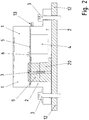
Figur 2 ist ein Querschnitt durch den schematischen Aufbau eines zweiten erfindungsgemäßen Ausführungsbeispiels gezeigt. - In der
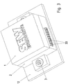
Figur 3 ist eine Schrägansicht auf das erste oder zweite Ausführungsbeispiel gezeigt. - Wie in
Figur 1 gezeigt, ist eine mit einem Wärme erzeugenden Bauelement 6 bestückte Leiterplatte 5 beidseitig von Schaumstoffteilen (1, 2) umgeben. - Hierzu ist ein erstes Schaumstoffteil 1 an die erste Seite der Leiterplatte 5, auf der auch das Bauelement 6 angeordnet ist, angesetzt.
- Auf der anderen Seite der Leiterplatte 5 ist ein Leistungsmodul 9 bestückt, welches Leistungshalbleiter aufweist und somit auch eine hohe Wärmeleistung besitzt. Die Leiterplatte 5 ist samt Leistungsmodul 9 umgeben von dem zweiten Schaumstoffteil 2.
- Die beiden Schaumstoffteile (1, 2) bilden gleichzeitig das Gehäuse. Sie umgeben also die bestückte Leiterplatte gehäusebildend.
- Außerdem sind zumindest eines oder beide Schaumstoffteile (1, 2) auf wärmeleitfähigem Grundmaterial gefertigt.
- Das Grundmaterial besteht aus Polypropylen, aus einem nichtoxydischen Keramik-Material, wie Siliciumcarbid, Bornitrid und/oder Borcarbid, und weiteren Zusätzen für Verbesserung des Flammschutzes und Verringerung des Kriechstroms, also Verbesserung der elektrischen Isolationsfestigkeit. Der Volumenanteil des Keramik-Materials, das als feines Pulver bei der Herstellung beigemischt wird, beträgt zwischen 3% und 30%. Somit ist eine hervorragende Wärmeleitfähigkeit erreichbar, obwohl das Grundmaterial aufgeschäumt wird und somit als Schaumstoffteil mit hohem Anteil an Gaseinschlüssen hergestellt ist. Zwar leiten die Gaseinschlüsse die Wärme sehr schlecht, jedoch sind die durch die Keramik-MaterialPartikel gebildeten Ketten in den aus dem Grundmaterial gebildeten Zellwänden derart als teilweise unterbrochen Ketten von der Wärmequelle zur Wärmesenke angeordnet, dass ein sehr geringer Wärmewiderstand durch das oder die Schaumstoffteile erreichbar ist.
- Die Schaumstoffteile (1, 2) halten die bestückte Leiterplatte auch mechanisch und werden mittels schrauben 3, welche vorzugsweise einen verbreiterten Schraubenkopf aufweisen und/oder unter deren Schraubenkopf eine Unterlegscheibe angeordnet ist, gegen ein Montageteil 12, insbesondere Tisch oder Wand, gedrückt, indem die Schrauben 3 dort zumindest teilweise eingeschraubt sind.
- Auf derselben Seite der Leiterplatte 5, auf welcher sich das Leistungsmodul 9 befeindet, ist auch ein Kondensator 4 vorgesehen, der als Zwischenkreiskondensators des von der bestückten Leiterplatte realisierten Umrichters fungiert.
- Das Wärme erzeugende Bauelement 6 ist mit seinen Anschlusselementen lötverbunden mit Leiterbahnen der Leiterplatte.
- Hingegen ist zum Verbinden des Leistungsmoduls 9 mit der Leiterplatte 5 eine Schraube 7 vorgesehen, deren Schraubenkopf auf eine Druckplatte 8 drückt, die - wie auch der Schraubenkopf - auf der von dem Leistungsmodul abgewandten Seite der Leiterplatte sich befindet.
- Die Schraube 7 wird zur Erzeugung dieser Anpresskraft mit einer Mutter 10 verbunden, welche wiederum über eine Druckplatte auf das Leistungsmodul drückt, wobei die Mutter 10 und die Druckplatte 11 auf der von der Leiterplatte abgewandten Seite des Leistungsmoduls angeordnet sind.
- Auf der Leiterplatte 5 ist auch ein Steckverbinderteil lötverbunden, dessen Kontakte aus dem Schaumstoffteil 2 herausragen, so dass von außen ein Gegensteckverbinderteil verbindbar ist. Auf diese Weise ist die Leiterplatte mit einem Datenbus verbindbar oder mittels einer sonstigen Datenschnittstelle zu einem weiteren Gerät verbindbar.
- Wie in
Figur 3 gezeigt, ist außerdem ein weiteres Steckverbinderteil 30 mit der Leiterplatte 5 lötverbindbar, so dass Versorgungsleitungen über ein Gegensteckverbinderteil, welches mit den ebenfalls aus dem Schaumstoffteil 2 herausragenden Kontakten des Steckverbinderteils 30 verbindbar ist. - Auf diese Weise ist also eine Leiterplatte bestückbar mit Bauelementen, einem Modul und Steckverbinderteilen, wonach die bestückte Leiterplatte von Schaumstoffteilen umgeben wird, insbesondere von entsprechend heißgeprägten Schaumstoffteilen.
- Das so entstandene Elektrogerät ist transportfähig und anbaufähig an ein Montageteil 12.
- Statt der Schaumstoffteile ist auch ein Umschäumen in einem Werkzeug ermöglicht. Beispielsweise wird hierzu die Leiterplatte in dem Werkzeug angeordnet, von kugelförmigen Grundmaterial-Teilchen umgeben und danach mit heißem Wasserdampf beaufschlagt, chemisch aufgeschäumt und/oder mit einem mehrkomponentigen Gemisch aufgeschäumt.
- Auf diese Weise ist dann das Herstellen von einzelnen Schaumstoffteilen verzichtbar und das Gehäuse ist in einem einzigen Schritt herstellbar.
- Wie in
Figur 2 gezeigt, ist auch ein Kühlkörper 20 mit dem Leistungsmodul 5 verbindbar, so dass die Wärme des Leistungsmodul aus dem von den Schaumstoffteilen (1, 2) gebildeten Gehäuse über den direkten Kontakt vom Leistungsmodul 5 mit dem Kühlkörper 20 herausführbar ist an die Umgebung, insbesondere das Montageteil 12. Die Wärme, welche von dem Bauelement 6 und/oder von dem Kondensator 4 erzeugt wird, wird weiterhin über die wärmeleitenden Schaumstoffteile 1 beziehungsweise 2 an die Umgebung abgeführt. - Bei einem weiteren erfindungsgemäßen Ausführungsbeispiel werden statt der beiden Schaumstoffteile (1, 2) mehr oder weniger Schaumstoffteile verwendet zur Bildung der Gehäusefunktion, der Wärmeableitfunktion und der mechanischen Haltefunktion für die Leiterplatte samt Bestückung.
-
- 1 Schaumstoffteil, insbesondere Kunststoff-Schaumstoffteil
- 2 Schaumstoffteil
- 3 Schraube, insbesondere mit verbreitertem Schraubenkopf und/oder Unterlegscheibe
- 4 Kondensator
- 5 Leiterplatte
- 6 Wärme erzeugendes Bauelement
- 7 Schraube
- 8 Druckplatte
- 9 Leistungsmodul
- 10 Mutter
- 11 Druckplatte
- 12 Montageteil, insbesondere Tisch oder Wand
- 13 Steckverbinderteil
- 20 Kühlkörper
- 30 Steckverbinderteil
Claims (8)
- Elektrogerät, aufweisend eine bestückte Leiterplatte (5) und zumindest ein Wärme leitender Schaumstoffteil (1, 2)
wobei das Schaumstoffteil (1, 2) die Leiterplatte (5) zumindest teilweise gehäusebildend umgibt,
wobei im Schaumstoff ein metallisches Teil, insbesondere aus Aluminium oder Kupfer, angeordnet ist, welches aus dem Schaumstoff in die Umgebung herausragt um die Wärmeableitung zu verbessern und das von der Leiterplatte (5) und den darauf bestückten Bauelementen (6) beabstandet ist. - Elektrogerät nach Anspruch 1,
dadurch gekennzeichnet, dass
der Schaumstoff aus einem aufgeschäumten Grundmaterial besteht, welches Polypropylen und ein nicht-oxydisches Keramik-Material enthält,
insbesondere welches Siliciumcarbid, Bornitrid und/oder Borcarbid aufweist,
insbesondere mit einem Volumenanteil zwischen 3 % und 30 %. - Elektrogerät nach mindestens einem der vorangegangenen Ansprüche,
dadurch gekennzeichnet, dass
ein oder mehrere Wärme erzeugende Bauelemente (6) auf der Leiterplatte (5) bestückt sind. - Elektrogerät nach mindestens einem der vorangegangenen Ansprüche,
dadurch gekennzeichnet, dass
die Schaumstoffteile (1, 2) miteinander formschlüssig verbunden sind, insbesondere schraubverbunden oder mittels Klipsverbindung. - Elektrogerät nach mindestens einem der vorangegangenen Ansprüche,
dadurch gekennzeichnet, dass
das Elektrogerät mittels Schrauben (3, 7) an ein Montageteil (12), insbesondere metallisches Montageteil (12), anschraubbar ist, wobei die Schrauben (3, 7) Anpresskraftfluss in ein oder das Schaumstoffteil (1, 2) einleiten. - Elektrogerät nach mindestens einem der vorangegangenen Ansprüche,
dadurch gekennzeichnet, dass
ein Wärme erzeugendes Leistungsmodul, welches mit der Leiterplatte (5) verbunden ist, auf einer von der Leiterplatte (5) abgewandten Seite mit einem Kühlkörper (20), insbesondere mit einem Aluminium-Kühlkörper (20), verbunden ist, welcher ein Schaumstoffteil (1, 2) durchdringt, insbesondere und an seinem von dem Leistungsmodul abgewandten Seite in die Umgebung mündet, insbesondere in das Montageteil (12). - Elektrogerät nach mindestens einem der vorangegangenen Ansprüche,
dadurch gekennzeichnet, dass
mindestens ein Steckverbinderteil (13, 30) auf der Leiterplatte (5) bestückt ist, welches aus einem oder dem Schaumstoffteil (1, 2) herausragt, insbesondere zur Verbindung mit einem Gegensteckverbinderteil. - Elektrogerät nach mindestens einem der vorangegangenen Ansprüche,
dadurch gekennzeichnet, dass
das Leistungsmodul mit der Leiterplatte (5) schraubverbunden ist,
insbesondere wobei eine Druckplatte (8, 11) auf der vom Leistungsmodul abgewandten Seite von einer Schraubverbindung gegen die Leiterplatte (5) gedrückt wird und das Leistungsmodul gegen die Leiterplatte (5) von der Schraubverbindung gedrückt wird.
Priority Applications (1)
| Application Number | Priority Date | Filing Date | Title |
|---|---|---|---|
| PL13700613T PL2805589T3 (pl) | 2012-01-19 | 2013-01-09 | Przyrząd elektryczny |
Applications Claiming Priority (2)
| Application Number | Priority Date | Filing Date | Title |
|---|---|---|---|
| DE102012000907.0A DE102012000907B4 (de) | 2012-01-19 | 2012-01-19 | Elektrogerät |
| PCT/EP2013/000036 WO2013107615A1 (de) | 2012-01-19 | 2013-01-09 | Elektrogerät |
Publications (2)
| Publication Number | Publication Date |
|---|---|
| EP2805589A1 EP2805589A1 (de) | 2014-11-26 |
| EP2805589B1 true EP2805589B1 (de) | 2018-12-19 |
Family
ID=47594631
Family Applications (1)
| Application Number | Title | Priority Date | Filing Date |
|---|---|---|---|
| EP13700613.6A Active EP2805589B1 (de) | 2012-01-19 | 2013-01-09 | Elektrogerät |
Country Status (7)
| Country | Link |
|---|---|
| US (1) | US9949404B2 (de) |
| EP (1) | EP2805589B1 (de) |
| CN (1) | CN104054405B (de) |
| DE (1) | DE102012000907B4 (de) |
| HU (1) | HUE042597T2 (de) |
| PL (1) | PL2805589T3 (de) |
| WO (1) | WO2013107615A1 (de) |
Families Citing this family (3)
| Publication number | Priority date | Publication date | Assignee | Title |
|---|---|---|---|---|
| US9237679B2 (en) * | 2011-02-04 | 2016-01-12 | Sew-Eurodrive Gmbh & Co. Kg | Electrical device |
| DE102017111796A1 (de) * | 2017-05-30 | 2018-12-06 | Thyssenkrupp Ag | Elektronische Steuereinheit für eine Lenkkraftunterstützungseinheit |
| DE102018216894A1 (de) * | 2018-10-02 | 2020-04-02 | Volkswagen Aktiengesellschaft | Tragelement mit zumindest einer elektrischen und/oder elektronischen Komponente sowie Baugruppe mit einem derartigen Tragelement |
Family Cites Families (14)
| Publication number | Priority date | Publication date | Assignee | Title |
|---|---|---|---|---|
| DE4237870A1 (de) | 1992-11-10 | 1994-03-10 | Daimler Benz Ag | Verfahren zur Herstellung eines elektronischen Steuergeräts für ein Kraftfahrzeug, und nach diesem Verfahren herstellbares Steuergerät |
| DE4437664A1 (de) | 1994-10-21 | 1996-04-25 | Bosch Gmbh Robert | Elektrisches Gerät und Verfahren zu dessen Herstellung |
| US5755026A (en) * | 1996-08-15 | 1998-05-26 | Delco Electronics Corporation | Method of preventing condensation on a surface housing an electronic apparatus |
| WO1999059225A1 (en) | 1998-05-08 | 1999-11-18 | Ut Automotive Dearborn, Inc. | Foamed housing for a circuit board |
| CN2339275Y (zh) | 1998-10-16 | 1999-09-22 | 张淑贞 | 可拆式发光玩具球 |
| US7744991B2 (en) * | 2003-05-30 | 2010-06-29 | 3M Innovative Properties Company | Thermally conducting foam interface materials |
| US10390647B2 (en) * | 2004-04-08 | 2019-08-27 | Parallax Group International, Llc | Floor matting |
| DE102007029913A1 (de) * | 2007-06-28 | 2009-01-02 | Robert Bosch Gmbh | Elektrisches Steuergerät |
| US8376036B2 (en) * | 2007-11-02 | 2013-02-19 | Az Evap, Llc | Air to air heat exchanger |
| EP2071911B1 (de) * | 2007-12-11 | 2011-12-21 | Denso Corporation | Elektrische Steuervorrichtung und Herstellungsverfahren dafür |
| DE102008060062A1 (de) | 2008-12-02 | 2010-06-17 | S-Y Systems Technologies Europe Gmbh | Elektrischer Stromverteiler und Verfahren zur Herstellung des elektrischen Stromverteilers |
| US20100142154A1 (en) * | 2008-12-04 | 2010-06-10 | Microvision, Inc. | Thermally Dissipative Enclosure Having Shock Absorbing Properties |
| DE102011010434B4 (de) | 2011-02-04 | 2025-03-13 | Sew-Eurodrive Gmbh & Co Kg | Elektrisches Gerät |
| US9237679B2 (en) * | 2011-02-04 | 2016-01-12 | Sew-Eurodrive Gmbh & Co. Kg | Electrical device |
-
2012
- 2012-01-19 DE DE102012000907.0A patent/DE102012000907B4/de active Active
-
2013
- 2013-01-09 US US14/373,807 patent/US9949404B2/en active Active
- 2013-01-09 WO PCT/EP2013/000036 patent/WO2013107615A1/de not_active Ceased
- 2013-01-09 HU HUE13700613A patent/HUE042597T2/hu unknown
- 2013-01-09 EP EP13700613.6A patent/EP2805589B1/de active Active
- 2013-01-09 PL PL13700613T patent/PL2805589T3/pl unknown
- 2013-01-09 CN CN201380005746.5A patent/CN104054405B/zh active Active
Non-Patent Citations (1)
| Title |
|---|
| None * |
Also Published As
| Publication number | Publication date |
|---|---|
| US9949404B2 (en) | 2018-04-17 |
| DE102012000907B4 (de) | 2025-01-02 |
| EP2805589A1 (de) | 2014-11-26 |
| US20150029671A1 (en) | 2015-01-29 |
| DE102012000907A1 (de) | 2013-07-25 |
| CN104054405A (zh) | 2014-09-17 |
| HUE042597T2 (hu) | 2019-07-29 |
| WO2013107615A1 (de) | 2013-07-25 |
| PL2805589T3 (pl) | 2019-05-31 |
| CN104054405B (zh) | 2016-08-31 |
Similar Documents
| Publication | Publication Date | Title |
|---|---|---|
| DE102014112330B4 (de) | Überspritzte Substrat-Chip-Anordnung mit Wärmesenke, Motorsteuermodul und zugehöriges Herstellverfahren | |
| EP2671434B1 (de) | Elektrisches gerät | |
| DE112015004024B4 (de) | Schaltungsbaugruppe und elektrischer Verteiler | |
| DE112015003987B4 (de) | Schaltungsbaugruppe, elektrischer Verteiler und Herstellungsverfahren für eine Schaltungsbaugruppe | |
| DE112018002422B4 (de) | Schaltungsanordnung und elektrischer Verteilerkasten | |
| EP2043412A1 (de) | Stromschiene mit Wärmeableitung | |
| EP2327286B1 (de) | Schaltungsgehäuse mit wärmekopplungselement | |
| DE102018117378A1 (de) | Leistungsversorgung, Lampe, bewegliche Vorrichtung und Verfahren zur Herstellung einer Leistungsversorgung | |
| EP3014961A1 (de) | Elektrisches steuergerät | |
| EP2191703A2 (de) | Gehäuse für eine elektrische schaltung, insbesondere eines steuergeräts eines fahrzeugs | |
| EP1445799A2 (de) | Kühleinrichtung für Halbleiter auf Leiterplatte | |
| DE102015219851B4 (de) | Steuergerät | |
| EP2716145B1 (de) | Leiterplatte für elektrische bauelemente und leiterplattensystem | |
| WO2023147816A1 (de) | Elektrisches system und elektrische antriebseinheit | |
| DE102011119490A1 (de) | Elektrisches Gerät und Verfahren | |
| DE102012000907B4 (de) | Elektrogerät | |
| DE202010017443U1 (de) | Elektrische Baugruppe | |
| DE102021210594B4 (de) | Leistungshalbleitermodul und Antriebsstrang für ein Fahrzeug aufweisend ein derartiges Leistungshalbleitermodul | |
| DE102021210597B4 (de) | Leistungshalbleitermodul und Antriebsstrang für ein Fahrzeug aufweisend ein derartiges Leistungshalbleitermodul | |
| DE19904279B4 (de) | Halbleitervorrichtung | |
| DE102012000908A1 (de) | Elektrogerät | |
| DE102006009812B4 (de) | Montageanordnung für mehrere Leistungshalbleiter und Schaltung mit einer solchen Montageanordnung | |
| DE102019126311B3 (de) | Stromleitendes Kühlelement, System und Verfahren zur Wärmeabführung von leistungselektronischen Bauteilen auf Platinen | |
| DE10300175B4 (de) | Elektronische Baugruppe mit Wärme ableitendem Gehäuseteil | |
| EP3267501B1 (de) | Bestückung von thermisch hochleitfähigen bauteilen zur wärmespreizung |
Legal Events
| Date | Code | Title | Description |
|---|---|---|---|
| PUAI | Public reference made under article 153(3) epc to a published international application that has entered the european phase |
Free format text: ORIGINAL CODE: 0009012 |
|
| 17P | Request for examination filed |
Effective date: 20140819 |
|
| AK | Designated contracting states |
Kind code of ref document: A1 Designated state(s): AL AT BE BG CH CY CZ DE DK EE ES FI FR GB GR HR HU IE IS IT LI LT LU LV MC MK MT NL NO PL PT RO RS SE SI SK SM TR |
|
| DAX | Request for extension of the european patent (deleted) | ||
| REG | Reference to a national code |
Ref country code: DE Ref legal event code: R079 Ref document number: 502013011837 Country of ref document: DE Free format text: PREVIOUS MAIN CLASS: H05K0005000000 Ipc: H05K0007020000 |
|
| GRAP | Despatch of communication of intention to grant a patent |
Free format text: ORIGINAL CODE: EPIDOSNIGR1 |
|
| STAA | Information on the status of an ep patent application or granted ep patent |
Free format text: STATUS: GRANT OF PATENT IS INTENDED |
|
| RIC1 | Information provided on ipc code assigned before grant |
Ipc: H05K 7/20 20060101ALI20180628BHEP Ipc: H05K 5/00 20060101ALI20180628BHEP Ipc: H05K 7/02 20060101AFI20180628BHEP |
|
| INTG | Intention to grant announced |
Effective date: 20180730 |
|
| GRAS | Grant fee paid |
Free format text: ORIGINAL CODE: EPIDOSNIGR3 |
|
| GRAA | (expected) grant |
Free format text: ORIGINAL CODE: 0009210 |
|
| STAA | Information on the status of an ep patent application or granted ep patent |
Free format text: STATUS: THE PATENT HAS BEEN GRANTED |
|
| AK | Designated contracting states |
Kind code of ref document: B1 Designated state(s): AL AT BE BG CH CY CZ DE DK EE ES FI FR GB GR HR HU IE IS IT LI LT LU LV MC MK MT NL NO PL PT RO RS SE SI SK SM TR |
|
| REG | Reference to a national code |
Ref country code: GB Ref legal event code: FG4D Free format text: NOT ENGLISH |
|
| REG | Reference to a national code |
Ref country code: CH Ref legal event code: EP Ref country code: CH Ref legal event code: NV Representative=s name: HEPP WENGER RYFFEL AG, CH |
|
| REG | Reference to a national code |
Ref country code: IE Ref legal event code: FG4D Free format text: LANGUAGE OF EP DOCUMENT: GERMAN |
|
| REG | Reference to a national code |
Ref country code: AT Ref legal event code: REF Ref document number: 1080099 Country of ref document: AT Kind code of ref document: T Effective date: 20190115 |
|
| REG | Reference to a national code |
Ref country code: DE Ref legal event code: R096 Ref document number: 502013011837 Country of ref document: DE |
|
| REG | Reference to a national code |
Ref country code: SE Ref legal event code: TRGR |
|
| REG | Reference to a national code |
Ref country code: NL Ref legal event code: FP |
|
| PG25 | Lapsed in a contracting state [announced via postgrant information from national office to epo] |
Ref country code: NO Free format text: LAPSE BECAUSE OF FAILURE TO SUBMIT A TRANSLATION OF THE DESCRIPTION OR TO PAY THE FEE WITHIN THE PRESCRIBED TIME-LIMIT Effective date: 20190319 Ref country code: BG Free format text: LAPSE BECAUSE OF FAILURE TO SUBMIT A TRANSLATION OF THE DESCRIPTION OR TO PAY THE FEE WITHIN THE PRESCRIBED TIME-LIMIT Effective date: 20190319 Ref country code: HR Free format text: LAPSE BECAUSE OF FAILURE TO SUBMIT A TRANSLATION OF THE DESCRIPTION OR TO PAY THE FEE WITHIN THE PRESCRIBED TIME-LIMIT Effective date: 20181219 Ref country code: LV Free format text: LAPSE BECAUSE OF FAILURE TO SUBMIT A TRANSLATION OF THE DESCRIPTION OR TO PAY THE FEE WITHIN THE PRESCRIBED TIME-LIMIT Effective date: 20181219 Ref country code: LT Free format text: LAPSE BECAUSE OF FAILURE TO SUBMIT A TRANSLATION OF THE DESCRIPTION OR TO PAY THE FEE WITHIN THE PRESCRIBED TIME-LIMIT Effective date: 20181219 |
|
| REG | Reference to a national code |
Ref country code: LT Ref legal event code: MG4D |
|
| PG25 | Lapsed in a contracting state [announced via postgrant information from national office to epo] |
Ref country code: GR Free format text: LAPSE BECAUSE OF FAILURE TO SUBMIT A TRANSLATION OF THE DESCRIPTION OR TO PAY THE FEE WITHIN THE PRESCRIBED TIME-LIMIT Effective date: 20190320 Ref country code: RS Free format text: LAPSE BECAUSE OF FAILURE TO SUBMIT A TRANSLATION OF THE DESCRIPTION OR TO PAY THE FEE WITHIN THE PRESCRIBED TIME-LIMIT Effective date: 20181219 Ref country code: AL Free format text: LAPSE BECAUSE OF FAILURE TO SUBMIT A TRANSLATION OF THE DESCRIPTION OR TO PAY THE FEE WITHIN THE PRESCRIBED TIME-LIMIT Effective date: 20181219 |
|
| REG | Reference to a national code |
Ref country code: HU Ref legal event code: AG4A Ref document number: E042597 Country of ref document: HU |
|
| PG25 | Lapsed in a contracting state [announced via postgrant information from national office to epo] |
Ref country code: ES Free format text: LAPSE BECAUSE OF FAILURE TO SUBMIT A TRANSLATION OF THE DESCRIPTION OR TO PAY THE FEE WITHIN THE PRESCRIBED TIME-LIMIT Effective date: 20181219 Ref country code: PT Free format text: LAPSE BECAUSE OF FAILURE TO SUBMIT A TRANSLATION OF THE DESCRIPTION OR TO PAY THE FEE WITHIN THE PRESCRIBED TIME-LIMIT Effective date: 20190419 |
|
| PG25 | Lapsed in a contracting state [announced via postgrant information from national office to epo] |
Ref country code: IS Free format text: LAPSE BECAUSE OF FAILURE TO SUBMIT A TRANSLATION OF THE DESCRIPTION OR TO PAY THE FEE WITHIN THE PRESCRIBED TIME-LIMIT Effective date: 20190419 Ref country code: SK Free format text: LAPSE BECAUSE OF FAILURE TO SUBMIT A TRANSLATION OF THE DESCRIPTION OR TO PAY THE FEE WITHIN THE PRESCRIBED TIME-LIMIT Effective date: 20181219 Ref country code: SM Free format text: LAPSE BECAUSE OF FAILURE TO SUBMIT A TRANSLATION OF THE DESCRIPTION OR TO PAY THE FEE WITHIN THE PRESCRIBED TIME-LIMIT Effective date: 20181219 Ref country code: EE Free format text: LAPSE BECAUSE OF FAILURE TO SUBMIT A TRANSLATION OF THE DESCRIPTION OR TO PAY THE FEE WITHIN THE PRESCRIBED TIME-LIMIT Effective date: 20181219 Ref country code: RO Free format text: LAPSE BECAUSE OF FAILURE TO SUBMIT A TRANSLATION OF THE DESCRIPTION OR TO PAY THE FEE WITHIN THE PRESCRIBED TIME-LIMIT Effective date: 20181219 |
|
| REG | Reference to a national code |
Ref country code: DE Ref legal event code: R097 Ref document number: 502013011837 Country of ref document: DE |
|
| PG25 | Lapsed in a contracting state [announced via postgrant information from national office to epo] |
Ref country code: LU Free format text: LAPSE BECAUSE OF NON-PAYMENT OF DUE FEES Effective date: 20190109 |
|
| PLBE | No opposition filed within time limit |
Free format text: ORIGINAL CODE: 0009261 |
|
| STAA | Information on the status of an ep patent application or granted ep patent |
Free format text: STATUS: NO OPPOSITION FILED WITHIN TIME LIMIT |
|
| REG | Reference to a national code |
Ref country code: IE Ref legal event code: MM4A |
|
| PG25 | Lapsed in a contracting state [announced via postgrant information from national office to epo] |
Ref country code: DK Free format text: LAPSE BECAUSE OF FAILURE TO SUBMIT A TRANSLATION OF THE DESCRIPTION OR TO PAY THE FEE WITHIN THE PRESCRIBED TIME-LIMIT Effective date: 20181219 Ref country code: MC Free format text: LAPSE BECAUSE OF FAILURE TO SUBMIT A TRANSLATION OF THE DESCRIPTION OR TO PAY THE FEE WITHIN THE PRESCRIBED TIME-LIMIT Effective date: 20181219 |
|
| 26N | No opposition filed |
Effective date: 20190920 |
|
| PG25 | Lapsed in a contracting state [announced via postgrant information from national office to epo] |
Ref country code: IE Free format text: LAPSE BECAUSE OF NON-PAYMENT OF DUE FEES Effective date: 20190109 |
|
| PG25 | Lapsed in a contracting state [announced via postgrant information from national office to epo] |
Ref country code: SI Free format text: LAPSE BECAUSE OF FAILURE TO SUBMIT A TRANSLATION OF THE DESCRIPTION OR TO PAY THE FEE WITHIN THE PRESCRIBED TIME-LIMIT Effective date: 20181219 |
|
| PG25 | Lapsed in a contracting state [announced via postgrant information from national office to epo] |
Ref country code: TR Free format text: LAPSE BECAUSE OF FAILURE TO SUBMIT A TRANSLATION OF THE DESCRIPTION OR TO PAY THE FEE WITHIN THE PRESCRIBED TIME-LIMIT Effective date: 20181219 |
|
| PG25 | Lapsed in a contracting state [announced via postgrant information from national office to epo] |
Ref country code: MT Free format text: LAPSE BECAUSE OF FAILURE TO SUBMIT A TRANSLATION OF THE DESCRIPTION OR TO PAY THE FEE WITHIN THE PRESCRIBED TIME-LIMIT Effective date: 20181219 |
|
| PG25 | Lapsed in a contracting state [announced via postgrant information from national office to epo] |
Ref country code: CY Free format text: LAPSE BECAUSE OF FAILURE TO SUBMIT A TRANSLATION OF THE DESCRIPTION OR TO PAY THE FEE WITHIN THE PRESCRIBED TIME-LIMIT Effective date: 20181219 |
|
| PG25 | Lapsed in a contracting state [announced via postgrant information from national office to epo] |
Ref country code: MK Free format text: LAPSE BECAUSE OF FAILURE TO SUBMIT A TRANSLATION OF THE DESCRIPTION OR TO PAY THE FEE WITHIN THE PRESCRIBED TIME-LIMIT Effective date: 20181219 |
|
| PGFP | Annual fee paid to national office [announced via postgrant information from national office to epo] |
Ref country code: GB Payment date: 20251204 Year of fee payment: 14 |
|
| PGFP | Annual fee paid to national office [announced via postgrant information from national office to epo] |
Ref country code: FI Payment date: 20251230 Year of fee payment: 14 |
|
| PGFP | Annual fee paid to national office [announced via postgrant information from national office to epo] |
Ref country code: NL Payment date: 20251215 Year of fee payment: 14 Ref country code: FR Payment date: 20251208 Year of fee payment: 14 |
|
| PGFP | Annual fee paid to national office [announced via postgrant information from national office to epo] |
Ref country code: SE Payment date: 20251210 Year of fee payment: 14 |
|
| PGFP | Annual fee paid to national office [announced via postgrant information from national office to epo] |
Ref country code: CZ Payment date: 20251113 Year of fee payment: 14 |
|
| PGFP | Annual fee paid to national office [announced via postgrant information from national office to epo] |
Ref country code: PL Payment date: 20251008 Year of fee payment: 14 |
|
| REG | Reference to a national code |
Ref country code: CH Ref legal event code: U11 Free format text: ST27 STATUS EVENT CODE: U-0-0-U10-U11 (AS PROVIDED BY THE NATIONAL OFFICE) Effective date: 20260201 |
|
| PGFP | Annual fee paid to national office [announced via postgrant information from national office to epo] |
Ref country code: DE Payment date: 20260131 Year of fee payment: 14 |
|
| PGFP | Annual fee paid to national office [announced via postgrant information from national office to epo] |
Ref country code: AT Payment date: 20260109 Year of fee payment: 14 |
|
| PGFP | Annual fee paid to national office [announced via postgrant information from national office to epo] |
Ref country code: BE Payment date: 20260121 Year of fee payment: 14 Ref country code: IT Payment date: 20251219 Year of fee payment: 14 |
|
| PGFP | Annual fee paid to national office [announced via postgrant information from national office to epo] |
Ref country code: HU Payment date: 20260310 Year of fee payment: 14 |
|
| PGFP | Annual fee paid to national office [announced via postgrant information from national office to epo] |
Ref country code: CH Payment date: 20260201 Year of fee payment: 14 |