EP2454641B1 - Durchflussbegrenzer - Google Patents
Durchflussbegrenzer Download PDFInfo
- Publication number
- EP2454641B1 EP2454641B1 EP20100734896 EP10734896A EP2454641B1 EP 2454641 B1 EP2454641 B1 EP 2454641B1 EP 20100734896 EP20100734896 EP 20100734896 EP 10734896 A EP10734896 A EP 10734896A EP 2454641 B1 EP2454641 B1 EP 2454641B1
- Authority
- EP
- European Patent Office
- Prior art keywords
- spring
- flow
- spring tongue
- carrier
- differential pressure
- Prior art date
- Legal status (The legal status is an assumption and is not a legal conclusion. Google has not performed a legal analysis and makes no representation as to the accuracy of the status listed.)
- Not-in-force
Links
- 210000002105 tongue Anatomy 0.000 claims description 145
- 239000007788 liquid Substances 0.000 claims description 21
- 230000000630 rising effect Effects 0.000 claims 7
- 239000012530 fluid Substances 0.000 description 20
- 238000011144 upstream manufacturing Methods 0.000 description 6
- 238000011109 contamination Methods 0.000 description 3
- 238000005452 bending Methods 0.000 description 2
- 230000007423 decrease Effects 0.000 description 2
- 230000000284 resting effect Effects 0.000 description 2
- 229910000639 Spring steel Inorganic materials 0.000 description 1
- 238000004026 adhesive bonding Methods 0.000 description 1
- 230000006835 compression Effects 0.000 description 1
- 238000007906 compression Methods 0.000 description 1
- 230000001419 dependent effect Effects 0.000 description 1
- 230000000694 effects Effects 0.000 description 1
- 238000003780 insertion Methods 0.000 description 1
- 230000037431 insertion Effects 0.000 description 1
- 238000000034 method Methods 0.000 description 1
- 230000010355 oscillation Effects 0.000 description 1
- 210000002435 tendon Anatomy 0.000 description 1
- 230000007704 transition Effects 0.000 description 1
- 238000005406 washing Methods 0.000 description 1
Images


Classifications
-
- G—PHYSICS
- G05—CONTROLLING; REGULATING
- G05D—SYSTEMS FOR CONTROLLING OR REGULATING NON-ELECTRIC VARIABLES
- G05D7/00—Control of flow
- G05D7/01—Control of flow without auxiliary power
- G05D7/0106—Control of flow without auxiliary power the sensing element being a flexible member, e.g. bellows, diaphragm, capsule
- G05D7/012—Control of flow without auxiliary power the sensing element being a flexible member, e.g. bellows, diaphragm, capsule the sensing element being deformable and acting as a valve
-
- Y—GENERAL TAGGING OF NEW TECHNOLOGICAL DEVELOPMENTS; GENERAL TAGGING OF CROSS-SECTIONAL TECHNOLOGIES SPANNING OVER SEVERAL SECTIONS OF THE IPC; TECHNICAL SUBJECTS COVERED BY FORMER USPC CROSS-REFERENCE ART COLLECTIONS [XRACs] AND DIGESTS
- Y10—TECHNICAL SUBJECTS COVERED BY FORMER USPC
- Y10T—TECHNICAL SUBJECTS COVERED BY FORMER US CLASSIFICATION
- Y10T137/00—Fluid handling
- Y10T137/0318—Processes
- Y10T137/0324—With control of flow by a condition or characteristic of a fluid
- Y10T137/0379—By fluid pressure
Definitions
- the present invention relates to a flow restrictor for limiting a volume flow through a fluid line. More particularly, the present invention relates to a flow restrictor having a carrier with passage and a flat-form spring attached to the carrier, wherein the flat-form spring is adapted to be increasingly applied to the carrier with increasing differential pressure and thereby to reduce the opening.
- Flow restrictors or flow rate regulators limit the volume flow through a fluid line, e.g. a pipeline, within a defined operating range of the differential pressure and thus allow a constant volume flow through the line regardless of pressure changes in the line.
- a flow restrictor which comprises a centered on a round support designed mounted round flat shape spring.
- the carrier has a plurality of small round openings which are arranged on two concentric rings symmetrically around the center of the carrier and determine the maximum passage.
- the flat-form spring is flattened so that the open area between the pipeline and the flat-form spring is reduced.
- the flattening of the spring is not linear to the increasing pressure because the flattening begins in the center and progresses outwardly, and because the round configuration of the spring causes the flattened area to decrease rapidly as the flattening increases towards the edge region.
- the US-A-4,884,750 discloses a flow restrictor for limiting a volume flow through a fluid conduit having a carrier with passage and a curved spring attached to the carrier, which is adapted to increasingly flatten with increasing differential pressure ( ⁇ p).
- the various shapes of the springs either have the disadvantage of insufficient volume flow or begin to vibrate as the passage is closed.
- a flow restrictor for limiting a volume flow through a fluid conduit which comprises a carrier with passage and a flat-form spring attached to the carrier.
- the flat shape spring has at least one spring tongue and the passage at least one opening.
- the spring tongue is configured and arranged above the opening such that the spring tongue increasingly engages the carrier with increasing differential pressure, thereby reducing the opening and reducing the passage within a defined pressure range.
- a washing machine flow regulator which includes a fixed support member having openings that may be partially covered by plastic elements.
- the plastic elements are designed as round discs, which are arranged in its center lifted from the support element.
- the plastic elements bend with increasing pressure with their remote from the center outer edge regions in the direction of the support member so that they form a curved screen over the openings.
- two such plastic elements are arranged concentrically and one above the other at a defined distance, wherein the lower plastic elements have a larger Diameter than the upper plastic element has.
- the lower plastic element is also provided with openings which are covered umbrella-like in the direction of the support member when bending the upper plastic element.
- the flow restrictor for limiting a volume flow through a fluid line comprises a carrier with passage (passage opening) and a flat-form spring attached to the carrier.
- the flat shape spring comprises at least one spring tongue and the passage comprises at least one opening.
- the spring tongue is configured and arranged over the opening, that the spring tongue with increasing differential pressure increasingly applied to the carrier, thereby reducing the opening and reduces the passage within a defined pressure range.
- the spring tongue upstream of a body or the spring tongue in the flow direction is aligned so that the spring tongue provides a reduced by at least 25% flow cross section direct attack surface.
- the spring tongue is a body upstream or the spring tongue is aligned in the flow direction, that the spring tongue is directly exposed to a reduced cross-sectional part of the flow, which is less than 75% of the surface of the spring tongue.
- the flow cross-section of the spring tongue provides direct attack surface increases with increasing differential pressure with increasing application of the spring tongue to the carrier.
- the spring tongue and the corresponding opening each have a substantially equal extent along a longitudinal direction.
- the size of the spring tongue corresponding dimensioning of the opening can be achieved over the prior art with a comparable size of the flow restrictor an overall larger passage and a reduced risk of contamination.
- the flow restrictor can be made more compact and less susceptible to dirt.
- the spring tongue is defined at a low differential pressure Pressure range oriented in the flow direction, that the spring tongue runs in the majority in the flow direction and a reduced flow cross-sectional portion provides direct attack surface, which is less than 75% of the surface of the spring tongue, preferably a flow cross-sectional part between 8% and 25% of the spring tongue surface.
- the spring tongue relative to the longitudinal axis of the liquid line corresponding to an angle of less than 45 °, preferably an angle in the range of about 5 ° to about 15 °.
- the carrier has a counter-elevating ramp
- the spring tongue is designed such that it increasingly bends with increasing differential pressure and rests against the ramp, thereby continuously reducing the opening and continuously reducing the passage within the defined pressure range ,
- the spring tongue upstream body is arranged and arranged so that it at a low differential pressure of the defined pressure range for at least a surface portion of 25% of the spring tongue, preferably for a surface portion in the range of 90% to 100% of the spring tongue, a flow shadow (Projection shadows) generated.
- the carrier is substantially planar and the spring tongue is designed so that it increasingly flattened with increasing differential pressure and applies to the carrier while continuously reducing the opening and continuously reduces the passage within the defined pressure range.
- the passage comprises at least two adjacent openings and the carrier comprises a web which separates the adjacent openings from each other.
- the spring tongue is arranged so that it increasingly rests on the web with increasing differential pressure and continuously reduces the openings, the openings remain open in defined residual areas.
- the passage comprises a plurality of rotationally symmetrically arranged openings
- the flat shape spring comprises a plurality of rotationally symmetrically arranged spring tongues, which are each arranged so that they increasingly lie on the support with increasing differential pressure and reduce the openings continuously, i. increasingly cover up.
- the flat-form spring has at least two spring tongues oriented in mutually opposite directions along a common longitudinal axis.
- the spring tongues are attached to an outer edge region of the carrier, in the center of the carrier or on a fastening web extending through the center.
- the support is designed as a round disc, which at the outer edge region comprises a raised collar for insertion into a pipeline, e.g. into a connector between two pipes or into a valve, e.g. a ball valve or a globe valve.
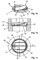
- the reference numeral 1 designates a flow restrictor, which is also referred to as a flow rate regulator and limits the volume flow through a liquid line 2 within a defined working range ( ⁇ p min , ⁇ p max ) of the differential pressure ⁇ p.
- a pressure-independent volumetric flow V ⁇ is achieved by reducing the passage of the flow restrictor 1, ie the flow cross section or the flow area, depending on the force generated from the differential pressure ⁇ p.
- the flow restrictor 1 comprises a flat-shaped spring 11 with a defined radius (of the order of magnitude of the liquid line 2, eg of the order of magnitude of the pipe diameter), which is fastened to a carrier 10 of the flow restrictor 1 and thus over the passage openings 13, 18, 23 , 23 'of the flow restrictor 1 is arranged so that it increasingly covers and closes the variable opening area, ie the passage of the flow restrictor 1, with increasing pressure ⁇ p.
- the flat-form spring 11 engages increasingly on the carrier 10, for example on a web 14, 24 and / or on side edges 29 of the openings 18, whereby the flat-form spring 11 is increasingly harder.
- the flat-shaped spring 11 is harder because its effective length is reduced by the increasing contact with the carrier 10.
- the passage openings are each designed as openings in the carrier 10.
- the carrier 10 is preferably designed to fit the cross section of the liquid line 2 around and has a protruding collar 15.
- the collar 15 is attached to the outer edge region of the disk-shaped carrier 10 and is produced in one piece with the carrier 10, for example by compression deformation.
- the collar 15 has a plurality of sections 15 'which are slightly spread apart and engage in corresponding receptacles 21, for example a groove, in the wall of the liquid line 2 and axially fix the flow restrictor 1 in the liquid line 2.
- a part of the collar 15 is bent back onto the carrier 10 and clamps the flat-shaped spring 11 on the carrier 10.
- the flat-form spring 11 can also be fastened to the carrier 10 by means of a rivet 16 or by gluing.
- the flat-shaped spring 11 comprises a spring tongue 12 and the carrier 10 has a passage with two adjacent openings 13.
- the two openings 13 and the spring tongue 12 in the longitudinal direction L has a substantially equal extent (length).
- the carrier 10 has a web 14, which separates the two openings 13 from each other.
- the flat shape spring 11 is attached to the outer edge region of the round carrier 10.
- the two openings 13 are rectangular or trapezoidal and extend from the outer edge region, where the flat-shaped spring 11 is fixed, to the opposite outer edge region of the carrier 10.
- the flat-shaped spring 11 and the spring tongue 12 along the longitudinal axis of the web 14, along (parallel aligned to the openings 13 and arranged above the openings 13 so that they continuously cover the openings 13 within the defined working range [ ⁇ p min , ⁇ p max] continuously with increasing increasing with increasing pressure differential Ap on the web 14 of the carrier 10 and closes, until the maximum concern of the spring tongue 12 a minimum Passage remains.
- the minimum passage is formed by residual areas remaining in the edge regions of the openings 13 facing away from the web 14, which are not covered by the spring tongue 12.
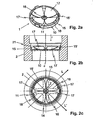
- the carrier 10 has a passage with four rotationally symmetrical openings 18, which are separated from one another by a web 14.
- the webs 14 can be considered as spokes of a wheel, which is formed from the circular support 10 through the openings 18.
- the openings 18 are each formed as approximately triangular circular sectors of the round carrier 10, which do not extend completely to the center of the carrier 10.
- the flat-form spring 11 comprises a plurality of rotationally symmetrically arranged spring tongues 17, 19, which are each arranged so that they increasingly rest on the carrier 10 with increasing differential pressure and reduce the openings 18 continuously.
- the flat-shaped spring 11 is mounted in the center Z of the carrier 10 and the spring tongues 17 are each associated with an opening 18.
- the openings 18 and the spring tongues 17 along the longitudinal direction L, L ' has a substantially equal extension (length).
- the spring tongues 17 are each arranged above an associated opening 18 so that they increasingly rest with increasing differential pressure ⁇ p on both webs 14, which limit the relevant opening 18.
- the openings 18 within the defined working range [ ⁇ p min , ⁇ p max ] are continuously increasingly covered and closed until the maximum contact of the spring tongue 17 remains a minimum passage.
- the minimum passage is formed at the openings 18 in each case by an open remaining residual area in the edge regions of the openings 18 facing away from the center Z, which are not covered by the spring tongues 17
- the flat-form spring 11 has an outer tire area 110, which is attached to the carrier 10.
- the spring tongues 19 are thus fastened to the outer edge region of the carrier 10.
- the spring tongues 19 are each arranged above an associated web 14 so that they each rest increasingly with increasing differential pressure ⁇ p on the respective web 14, and increasingly cover the two adjacent to the web 14 openings 18.
- the openings 18 within the defined working range [ ⁇ p min , ⁇ p max ] are continuously increasingly covered and closed until the maximum contact of the spring tongue 19 remains a minimum passage.
- the minimum passage is formed at the openings 18 in each case by an open area between two adjacent spring tongues 19 along the axis of symmetry of the relevant opening, which is not covered by the spring tongues 19.
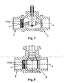
- FIG. 7 shows a cross section through a lifting valve 7 with removably or permanently installed flow restrictor 1 (according to one of the described embodiments) in the liquid supply line second
- FIG. 8 shows a cross section through a ball valve 8 with removable or fixed flow limiter 1 (according to one of the described embodiments) in the Liquid supply line 2.
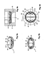
- FIGS. 9a, 9b, 9c and 9d show views, a cross section and plan views of a flow restrictor 1 with a flat-shaped spring 11, which has two attached to a transversely over the flow restrictor 1 between the outer edge regions extending fastening web 34 fixed spring tongues 27.
- the attachment of the spring 11 may be glued to the web 34, riveted or configured according to the above-mentioned other fastening method.
- Each portion of the spring 11, so each spring tongue 27 is mounted in each case via two openings 23 separated by a web 24. The openings thus take approximately, minus the webs 24 and 34 each a quadrant of the circular passage for the flow restrictor 1 a.
- recesses 43 are preferably embedded in the edge region of the spring tongues 27 with smoother transitions than illustrated. If the center axis of a spring tongue 27 arranged above the web 24 is assigned the angle 0 degrees in the radial direction, then these two recesses 43 of a spring tongue 27 are arranged at an angle between 20 and 45 degrees, in particular at approximately 30 degrees.
- the flat form spring 11 is when it is flattened and not in the FIG. 9c illustrated pre-bent shape has no perfect circular disk, but it is cut off in particular in the region of the central part 32.
- the section edge corresponds to a chord 47 of the circle.
- This chord 47 can be rounded in the lateral parts 33 in the circular edge of the spring 11 passed.
- a double remaining passage On the one hand, this is the area of the recesses 43 and, on the other hand, the space of the two openings 23 remaining beyond the chord 47. It is clear that in one exemplary embodiment, which is not shown in the drawings, only the recesses 43 can exist and at other times only the one through the chords predetermined remaining space of the two openings 23rd
- the collar 15 here also has a plurality of sections 15 ', which are slightly spread apart, and can axially fix the flow restrictor 1 in the fluid line 2.
- FIG. 10 shows a plan view of a flow restrictor 1 with a flat-shaped spring 11, which has four rotationally symmetrical arranged at the center Z of the flow restrictor 1 spring tongues 37.
- These spring tongues 37 are compared to the embodiment of FIG. 2 rotated by 45 degrees, so that they are each mounted on an associated web 24, which separates two each of a spring tongue 37 associated openings 23 from each other.
- each opening 23 here is assigned two spring tongues 37 in each case.
- the corners 48 of the spring tongues may be cut off to make further recesses, or it may recesses corresponding to the oval cutouts according to the embodiment of the Fig. 9 consist.
- FIG. 11 shows a plan view of another flow restrictor 1 with a flat-shaped spring 11, modified compared Fig. 9 whose two spring tongues 27 are each attached via two associated webs 24.
- the webs 24 intersect in the center at a 90 degree angle to each other and at a 45 degree angle to the mounting bar 34.
- the passage is so here in three each of a spring tongue 27 associated openings 23 separated.
- Recesses 43 and tendon section 47 correspond to those of Fig. 9 such that, in particular in the middle section 32, the remaining passage region remains open, while the lateral spring tongue regions deposit on the edge region 44 of the carrier 10. But it is also possible that the recesses 43 are also or only or additionally provided in the lateral areas 33.
- the flat-form spring 11 is preferably made of a spring steel, which is designed depending on the variant straight or pre-bent, in particular in the range between about 30 degrees, as in the embodiments of FIGS. 1 . 2 and 3 , or up to 80 degrees, as in the embodiments of Figures 9 and 11 ,
- the width of the webs 14 and 24 is designed so that it forms a secure mechanical bearing surface. For this purpose, a width of 5 to 10%, a maximum of 20% of the diameter of the flow restrictor 1 or the width of the flat shape spring 11 protruding on both sides is sufficient.
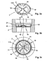
- FIGS. 4 and 5 the non-linear relationship between spring force F and deflection s is shown.
- FIG. 4 shows the relatively small deflection s of the flat-shaped spring 11 and a spring tongue 12, 17, 19, 27 of the flat-form spring 11 in a range with small pressure difference Ap and correspondingly smaller spring force F.
- FIG. 5 shows the comparatively large deflection s of the flat form spring 11 and the spring tongue 12, 17, 19, 27 in a region with a relatively large pressure difference .DELTA.p and correspondingly large and increasingly increasing spring force F.
- the reference character D max designates the (quantity) profile of the volume flow V ⁇ through the flow restrictor 1 as a function of the differential pressure ⁇ p at the maximum, uncontrolled passage (fully opened passage opening).
- the reference numeral D min denotes the (quantity) course of the volumetric flow V ⁇ through the flow restrictor 1 depending on the differential pressure Ap with minimal passage, which remains at full concern of the flat form spring 11 and the spring tongue 12, 17, 19, 27 open (open residual area at maximum closed passage opening).
- the flat-form spring 11 or the spring tongue 12, 17, 19, 27, 27 ' is deflected less strongly at low differential pressure values ⁇ p, respectively, and applied to the carrier 10, 10', and thus the passage is less (fast) reduced at low differential pressure values ⁇ p that the nominal flow rate, ie the constant volume flow value V const , is reached even at a smaller differential pressure ⁇ p min2 and thus an extended operating range [ ⁇ p min2 , ⁇ p max ] with constant volume flow value V const is achieved.
- the reduced flow exposure of the flat-form spring 11 or of the spring tongue 12, 17, 19, 27, 27 ' is achieved in that the spring tongue 12, 17, 19, 27 is preceded by a body, around the spring tongue 12, 17, 19, 27 to shield from direct impact of the flow, or in that the alignment of the spring tongue 12, 17, 19, 27 'majority takes place in the direction of flow r, to provide the flow a reduced attack surface.
- the Figures 12a, 12b, 12c illustrate a variant of the flow restrictor 1 with a flat-shaped spring 11 and an upstream body 50 in the flow direction r, which is attached to the carrier 10.
- the body 50 generates for at least a portion of the flat-form spring 11 and the spring tongues 27 a flow shadow, the flow shadow (as in the case of a light source) being understood as an (idealized) projection shadow, and any whirling effects are not taken into account.
- the body 50 completely shades the flat-shaped spring 11 and the spring tongues 27, respectively, from direct impingement of the flow and produces a 100% flow, ie projection shadow, as in the plan view of FIG FIG.
- the body 50 is preferably made of plastic and has a facing the flow and facing away from the flat spring 11 screen surface 51 which is perpendicular to the axial direction of the liquid line 2 and generates the flow shadow.
- the shielding surface 51 preferably has a basic shape corresponding to the inner cross section of the fluid conduit 2, which has one or more recesses serving as supply regions 52.
- the Figures 12a, 12b, 12c show the upstream body 50 in combination with a flow restrictor 1 according to the Figures 9a, 9b, 9c and 9d ,
- a body 50 shaped according to the respective variant can also be used in other embodiments of the flow restrictor 1 according to FIGS FIGS. 1 a, 1 b, 1 c, 2a, 2b, 2c . 3a, 3b, 3c . 10 and / or 11 the flat-shaped spring 11 respectively the spring tongues 12, 17, 19, 27 can be pre-stored.
- the screen surface 51 has, for example, a circular basic shape, which in the embodiments of the flow restrictor 1 after the Figures 1 a, 1 b, 1 c .
- the body 50 has curved feed walls 53, for example, which face the flat-shaped spring 11 and extend essentially in the feed regions 52 from the screen surface 51 of the body 50 to the fastening side of the body 50 facing away from the screen surface 51.
- feed gaps 54 which are essentially wedge-shaped between the feed walls 53 and the spring tongue 12, 17, 19, 27 and increase with increasing differential pressure ⁇ p and thus increasing deflection Enlarge spring tongue 12, 17, 19, 27.
- the feed walls 53 substantially taper the body 50 from the outer edge area of the screen surface 51 the body 50 to the attachment side of the body 50, for example in arched form and in the variants of the FIGS. 2a, 2b, 2c .
- the feed walls 53 extend the feed channel through the body 50 substantially from the screen surface 51 of the body 50 to the attachment side of the body 50 progressively toward the outer periphery of the carrier 10, for example, in an arched shape.
- the body 50 is fastened, for example, together with the flat-shaped spring 11 by means of a rivet, for example by rivet holes 55, or by bonding to the carrier 10.
- the body 50 is based, for example, on a cylindrical basic shape, the shell of which is formed by the curved feed walls 53 and the screen surface 51, and whose base and top surfaces 56, 57 are substantially circular-segment-shaped, the screen surface 51 pass through the circular chords and the Zulite pertain 53 through the circular arc of the base and top surface 56, 57.
- the base and top surfaces 56, 57 are correspondingly shaped round, ie the body 50 has rounded base and top surfaces 56, 57, which are each arranged perpendicular to the screen surface 51 and the Make body 50 in the ring formed by the collar 15 used.
- the body 50 is for example made hollow and provided at the base and top surfaces 56, 57 with openings.
- the body 50 and the flat-shaped spring 11 are attached to a fastening web 34.
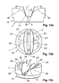
- FIG. 13a, 13b, 13c illustrate a variant of the flow restrictor 1, in which the (double-tongued) flat-shaped spring 11 and the spring tongues 27 'in the initial position, that is without a fluid flow and at low differential pressure values .DELTA.p, each unbent, ie flat outstretched shaped and majority in the flow direction r are aligned. That is, the spring tongues 27 'each straight and mostly in the direction of flow r and have with respect to the longitudinal axis a of the liquid line 2 each have an angle ⁇ of less than 45 °, preferably an angle ⁇ between 5 ° and 15 °, as in the cross section of FIG. 13a is apparent.
- the spring tongues 27 'of the flow offer a reduced attack surface at low differential pressure values ⁇ p.
- the Figures 13a, 13b, 13c show the flow restrictor 1 in a variant, which in the plan view substantially the embodiment according to the Figures 9a, 9b, 9c and 9d However, the eyed spring tongues 27 'substantially form a V-shaped cross-section.
- the flat-form spring 11 and the spring tongues 12, 17, 19, 27 and the carrier 10 can be adapted.
- the spring tongues 12, 17, 19, 27 can be set up and formed so that they are straight in the starting position and with respect to the longitudinal axis a of the liquid line 2 an angle ⁇ of less than 45 °, preferably an angle ⁇ between 15 ° and 25 °.
- the lying under the spring tongue 27 'region of the support 11' is in each case designed as a counter-elevation ramp 28, for example, with arcuate cross-section.
- the ramp 28 through the web 24 'and the side portions 29 of the openings 23' are formed.
- the thus formed ramp 28 rises, starting from the mounting region of the flat-shaped spring 11 on the carrier 10 ', in particular from the mounting web 34, in the counterflow direction before it drops slightly again in the arcuate variant.
- the ramp 28 rises in each case against the outer edge region of the carrier 10, 10 'towards; in the embodiments of the flow restrictor 1 according to the FIGS. 3a, 3b, 3c the ramp 28 rises in each case toward the center Z of the carrier 10.
- the spring tongue 27 'and the ramp 28 are formed so that the spring tongue 27 bends with increasing differential pressure Ap in the direction of the ramp 28, thereby increasingly applying to the ramp 28 and thus increasingly reduces the passage.
- the angle ⁇ of the spring tongue 27 'with respect to the longitudinal axis a of the liquid line 2 increases and the flow area exposed to the attack of the spring tongue 27' increases.
- the flow cross-section increases the flat shape spring 11 and the spring tongue (s) 12, 17, 19, 27, 27 ', 37 direct attack surface provides with increasing differential pressure during increasing application of the flat form spring 11 and the spring tongue (s) 12, 17, 19th , 27, 27 ', 37 to the carrier 10, 10'.
Landscapes
- Physics & Mathematics (AREA)
- General Physics & Mathematics (AREA)
- Engineering & Computer Science (AREA)
- Automation & Control Theory (AREA)
- Infusion, Injection, And Reservoir Apparatuses (AREA)
- Safety Valves (AREA)
- Finger-Pressure Massage (AREA)
Applications Claiming Priority (2)
| Application Number | Priority Date | Filing Date | Title |
|---|---|---|---|
| CH01100/09A CH701470A1 (de) | 2009-07-14 | 2009-07-14 | Durchflussbegrenzer. |
| PCT/CH2010/000180 WO2011006272A1 (de) | 2009-07-14 | 2010-07-14 | Durchflussbegrenzer |
Publications (2)
| Publication Number | Publication Date |
|---|---|
| EP2454641A1 EP2454641A1 (de) | 2012-05-23 |
| EP2454641B1 true EP2454641B1 (de) | 2013-08-28 |
Family
ID=41139320
Family Applications (1)
| Application Number | Title | Priority Date | Filing Date |
|---|---|---|---|
| EP20100734896 Not-in-force EP2454641B1 (de) | 2009-07-14 | 2010-07-14 | Durchflussbegrenzer |
Country Status (8)
| Country | Link |
|---|---|
| US (1) | US20120180875A1 (enExample) |
| EP (1) | EP2454641B1 (enExample) |
| CN (1) | CN102576229A (enExample) |
| CA (1) | CA2765425A1 (enExample) |
| CH (1) | CH701470A1 (enExample) |
| IN (1) | IN2012DN01202A (enExample) |
| RU (1) | RU2012105007A (enExample) |
| WO (1) | WO2011006272A1 (enExample) |
Families Citing this family (27)
| Publication number | Priority date | Publication date | Assignee | Title |
|---|---|---|---|---|
| US7648085B2 (en) | 2006-02-22 | 2010-01-19 | Rain Bird Corporation | Drip emitter |
| DE202011105376U1 (de) * | 2011-09-06 | 2012-12-10 | Neoperl Gmbh | Sanitäres Einbauteil |
| CN102434753A (zh) * | 2011-10-22 | 2012-05-02 | 成都市翻鑫家科技有限公司 | 双向油压缓冲器 |
| US9877440B2 (en) | 2012-03-26 | 2018-01-30 | Rain Bird Corporation | Elastomeric emitter and methods relating to same |
| DE202013000860U1 (de) | 2013-01-29 | 2014-05-05 | Neoperl Gmbh | Sanitäres Einbauteil und Komponente einer Sanitärarmatur |
| CN105307707B (zh) | 2013-05-15 | 2018-07-27 | 贝克顿·迪金森公司 | 在血液采集期间使用的真空压力调节器 |
| CA2911452C (en) * | 2013-05-15 | 2018-05-29 | Becton, Dickinson And Company | Vacuum pressure regulators for use during blood collection |
| US10631473B2 (en) | 2013-08-12 | 2020-04-28 | Rain Bird Corporation | Elastomeric emitter and methods relating to same |
| US10444768B2 (en) * | 2014-03-05 | 2019-10-15 | Jang Woo Lee | Flow-controlling unit provided in flow channel |
| US10059191B2 (en) | 2014-07-01 | 2018-08-28 | Denso International America, Inc. | Low resistance flow regulator |
| US9863083B2 (en) * | 2014-08-18 | 2018-01-09 | Haier Us Appliance Solutions, Inc. | Dispensing system utilizing mass flow of water |
| US10330559B2 (en) | 2014-09-11 | 2019-06-25 | Rain Bird Corporation | Methods and apparatus for checking emitter bonds in an irrigation drip line |
| US10375904B2 (en) | 2016-07-18 | 2019-08-13 | Rain Bird Corporation | Emitter locating system and related methods |
| US11051466B2 (en) | 2017-01-27 | 2021-07-06 | Rain Bird Corporation | Pressure compensation members, emitters, drip line and methods relating to same |
| US10626998B2 (en) | 2017-05-15 | 2020-04-21 | Rain Bird Corporation | Drip emitter with check valve |
| USD883048S1 (en) | 2017-12-12 | 2020-05-05 | Rain Bird Corporation | Emitter part |
| US11985924B2 (en) | 2018-06-11 | 2024-05-21 | Rain Bird Corporation | Emitter outlet, emitter, drip line and methods relating to same |
| NL2023494B1 (en) * | 2019-07-12 | 2021-02-04 | Hagepe Int B V | Device for limiting or keeping constant a flowing quantity of liquid |
| NL2023495B1 (en) * | 2019-07-12 | 2021-02-04 | Hagepe Int B V | Fluid flow regulator |
| EP4034959A1 (en) * | 2019-09-27 | 2022-08-03 | Danmarks Tekniske Universitet | Flow control by superposition of integrated non-linear valves |
| CN110701415A (zh) * | 2019-11-13 | 2020-01-17 | 中水北方勘测设计研究有限责任公司 | 保持流量稳定的过水器 |
| CN111022698B (zh) * | 2020-01-07 | 2020-07-31 | 中冶置业集团有限公司 | 管道装置以及用于沐浴的水流混合调控装置 |
| CN112945324B (zh) * | 2021-01-19 | 2023-04-07 | 山东瑞盛水表有限公司 | 一种高灵敏超声波感应管段式水表外壳 |
| CN113719688B (zh) * | 2021-10-08 | 2022-10-25 | 苏州高新区鼎正精密机电有限公司 | 一种限流效果好的可调式限流环 |
| US12207599B2 (en) | 2021-10-12 | 2025-01-28 | Rain Bird Corporation | Emitter coupler and irrigation system |
| WO2024074479A1 (en) * | 2022-10-04 | 2024-04-11 | Cenergist Limited | Flow regulating device for regulating a fluid flow therethrough |
| ES3046191T3 (en) * | 2022-10-04 | 2025-12-01 | Cenergist Ltd | Flow regulating device for regulating a fluid flow therethrough |
Family Cites Families (9)
| Publication number | Priority date | Publication date | Assignee | Title |
|---|---|---|---|---|
| US2899981A (en) * | 1959-08-18 | Certificate of correction | ||
| US2106775A (en) * | 1934-08-10 | 1938-02-01 | Mills Novelty Co | Valve |
| GB783323A (en) | 1954-09-08 | 1957-09-18 | Robertshaw Fulton Controls Co | Constant flow control valve |
| US3895646A (en) * | 1973-11-30 | 1975-07-22 | Manuel G Howat | Self-regulating vane type valve for controlling fluid flow |
| DE3308745A1 (de) * | 1983-03-11 | 1984-09-13 | Mannesmann + Keppel GmbH & Co KG, 8000 München | Durchflussmengenregler |
| AU594076B2 (en) | 1985-07-23 | 1990-03-01 | Winfried Jean Werding | Thrust regulator comprising a mounting housing |
| IT1234692B (it) * | 1989-05-17 | 1992-05-26 | Zanussi A Spa Industrie | Regolatore di portata di liquidi, in particolare per macchine lavatrici. |
| CN2632732Y (zh) * | 2003-07-21 | 2004-08-11 | 广东万家乐燃气具有限公司 | 流体声波稳流器 |
| RU2458380C2 (ru) * | 2007-11-15 | 2012-08-10 | Белимо Холдинг Аг | Ограничитель расхода |
-
2009
- 2009-07-14 CH CH01100/09A patent/CH701470A1/de unknown
-
2010
- 2010-07-14 US US13/378,806 patent/US20120180875A1/en not_active Abandoned
- 2010-07-14 IN IN1202DEN2012 patent/IN2012DN01202A/en unknown
- 2010-07-14 CA CA2765425A patent/CA2765425A1/en not_active Abandoned
- 2010-07-14 CN CN2010800323578A patent/CN102576229A/zh active Pending
- 2010-07-14 RU RU2012105007/28A patent/RU2012105007A/ru not_active Application Discontinuation
- 2010-07-14 WO PCT/CH2010/000180 patent/WO2011006272A1/de not_active Ceased
- 2010-07-14 EP EP20100734896 patent/EP2454641B1/de not_active Not-in-force
Also Published As
| Publication number | Publication date |
|---|---|
| IN2012DN01202A (enExample) | 2015-04-10 |
| EP2454641A1 (de) | 2012-05-23 |
| RU2012105007A (ru) | 2013-08-20 |
| CN102576229A (zh) | 2012-07-11 |
| US20120180875A1 (en) | 2012-07-19 |
| WO2011006272A1 (de) | 2011-01-20 |
| CH701470A1 (de) | 2011-01-14 |
| CA2765425A1 (en) | 2011-01-20 |
Similar Documents
| Publication | Publication Date | Title |
|---|---|---|
| EP2454641B1 (de) | Durchflussbegrenzer | |
| EP2210157B1 (de) | Durchflussbegrenzer | |
| DE10035640B4 (de) | Schwingungsdämpfer und Kolben hierfür | |
| DE2645501C2 (enExample) | ||
| EP3047165A1 (de) | Befestigungskralle | |
| DE112014004961T5 (de) | Stossdämpfer | |
| DE2555752B1 (de) | Drosselventil | |
| WO2016074867A1 (de) | Dämpfventil für einen schwingungsdämpfer | |
| DE202015103420U1 (de) | Getriebesteuervorrichtung | |
| DE3137319A1 (de) | Radblende mit einer halterung | |
| DE2349772C2 (de) | Absperrorgan | |
| DE102014211650A1 (de) | Bauteilverbindung | |
| EP3143470A1 (de) | Durchflussmengenregler | |
| WO2008089910A1 (de) | Ventileinrichtung für ein unterdruck-versorgungssystem | |
| DE10313162A1 (de) | Dichtring | |
| DE102009052609A1 (de) | Rückschlagventil | |
| DE102018214148A1 (de) | Dämpfventil für einen Schwingungsdämpfer | |
| DE3308745A1 (de) | Durchflussmengenregler | |
| WO2015106909A1 (de) | Bauteilverbindung | |
| DE1548932B2 (de) | Durchfluß Mengenregler | |
| DE69301274T2 (de) | Klappenventil mit verbesserter Dichtmanschette | |
| DE4327574C2 (de) | Torsionsdämpferscheibe | |
| DE102015203239A1 (de) | Kupplungsscheibe | |
| DE102018221290A1 (de) | Dämpfventil für einen Schwingungsdämpfer | |
| DE3541495C1 (de) | Federbelastetes Sicherheitsventil fuer Gase und Daempfe |
Legal Events
| Date | Code | Title | Description |
|---|---|---|---|
| PUAI | Public reference made under article 153(3) epc to a published international application that has entered the european phase |
Free format text: ORIGINAL CODE: 0009012 |
|
| 17P | Request for examination filed |
Effective date: 20111123 |
|
| AK | Designated contracting states |
Kind code of ref document: A1 Designated state(s): AL AT BE BG CH CY CZ DE DK EE ES FI FR GB GR HR HU IE IS IT LI LT LU LV MC MK MT NL NO PL PT RO SE SI SK SM TR |
|
| REG | Reference to a national code |
Ref country code: HK Ref legal event code: DE Ref document number: 1165568 Country of ref document: HK |
|
| DAX | Request for extension of the european patent (deleted) | ||
| GRAP | Despatch of communication of intention to grant a patent |
Free format text: ORIGINAL CODE: EPIDOSNIGR1 |
|
| GRAS | Grant fee paid |
Free format text: ORIGINAL CODE: EPIDOSNIGR3 |
|
| GRAA | (expected) grant |
Free format text: ORIGINAL CODE: 0009210 |
|
| AK | Designated contracting states |
Kind code of ref document: B1 Designated state(s): AL AT BE BG CH CY CZ DE DK EE ES FI FR GB GR HR HU IE IS IT LI LT LU LV MC MK MT NL NO PL PT RO SE SI SK SM TR |
|
| REG | Reference to a national code |
Ref country code: GB Ref legal event code: FG4D Free format text: NOT ENGLISH |
|
| REG | Reference to a national code |
Ref country code: CH Ref legal event code: EP |
|
| REG | Reference to a national code |
Ref country code: AT Ref legal event code: REF Ref document number: 629673 Country of ref document: AT Kind code of ref document: T Effective date: 20130915 |
|
| REG | Reference to a national code |
Ref country code: IE Ref legal event code: FG4D Free format text: LANGUAGE OF EP DOCUMENT: GERMAN |
|
| REG | Reference to a national code |
Ref country code: DE Ref legal event code: R096 Ref document number: 502010004525 Country of ref document: DE Effective date: 20131031 |
|
| REG | Reference to a national code |
Ref country code: LT Ref legal event code: MG4D |
|
| REG | Reference to a national code |
Ref country code: NL Ref legal event code: VDEP Effective date: 20130828 |
|
| PG25 | Lapsed in a contracting state [announced via postgrant information from national office to epo] |
Ref country code: HR Free format text: LAPSE BECAUSE OF FAILURE TO SUBMIT A TRANSLATION OF THE DESCRIPTION OR TO PAY THE FEE WITHIN THE PRESCRIBED TIME-LIMIT Effective date: 20130828 Ref country code: IS Free format text: LAPSE BECAUSE OF FAILURE TO SUBMIT A TRANSLATION OF THE DESCRIPTION OR TO PAY THE FEE WITHIN THE PRESCRIBED TIME-LIMIT Effective date: 20131228 Ref country code: NO Free format text: LAPSE BECAUSE OF FAILURE TO SUBMIT A TRANSLATION OF THE DESCRIPTION OR TO PAY THE FEE WITHIN THE PRESCRIBED TIME-LIMIT Effective date: 20131128 Ref country code: CY Free format text: LAPSE BECAUSE OF FAILURE TO SUBMIT A TRANSLATION OF THE DESCRIPTION OR TO PAY THE FEE WITHIN THE PRESCRIBED TIME-LIMIT Effective date: 20130828 Ref country code: LT Free format text: LAPSE BECAUSE OF FAILURE TO SUBMIT A TRANSLATION OF THE DESCRIPTION OR TO PAY THE FEE WITHIN THE PRESCRIBED TIME-LIMIT Effective date: 20130828 Ref country code: SE Free format text: LAPSE BECAUSE OF FAILURE TO SUBMIT A TRANSLATION OF THE DESCRIPTION OR TO PAY THE FEE WITHIN THE PRESCRIBED TIME-LIMIT Effective date: 20130828 Ref country code: PT Free format text: LAPSE BECAUSE OF FAILURE TO SUBMIT A TRANSLATION OF THE DESCRIPTION OR TO PAY THE FEE WITHIN THE PRESCRIBED TIME-LIMIT Effective date: 20131230 |
|
| REG | Reference to a national code |
Ref country code: NL Ref legal event code: VDEP Effective date: 20130828 |
|
| PG25 | Lapsed in a contracting state [announced via postgrant information from national office to epo] |
Ref country code: SI Free format text: LAPSE BECAUSE OF FAILURE TO SUBMIT A TRANSLATION OF THE DESCRIPTION OR TO PAY THE FEE WITHIN THE PRESCRIBED TIME-LIMIT Effective date: 20130828 Ref country code: FI Free format text: LAPSE BECAUSE OF FAILURE TO SUBMIT A TRANSLATION OF THE DESCRIPTION OR TO PAY THE FEE WITHIN THE PRESCRIBED TIME-LIMIT Effective date: 20130828 Ref country code: GR Free format text: LAPSE BECAUSE OF FAILURE TO SUBMIT A TRANSLATION OF THE DESCRIPTION OR TO PAY THE FEE WITHIN THE PRESCRIBED TIME-LIMIT Effective date: 20131129 Ref country code: PL Free format text: LAPSE BECAUSE OF FAILURE TO SUBMIT A TRANSLATION OF THE DESCRIPTION OR TO PAY THE FEE WITHIN THE PRESCRIBED TIME-LIMIT Effective date: 20130828 Ref country code: LV Free format text: LAPSE BECAUSE OF FAILURE TO SUBMIT A TRANSLATION OF THE DESCRIPTION OR TO PAY THE FEE WITHIN THE PRESCRIBED TIME-LIMIT Effective date: 20130828 |
|
| PG25 | Lapsed in a contracting state [announced via postgrant information from national office to epo] |
Ref country code: SK Free format text: LAPSE BECAUSE OF FAILURE TO SUBMIT A TRANSLATION OF THE DESCRIPTION OR TO PAY THE FEE WITHIN THE PRESCRIBED TIME-LIMIT Effective date: 20130828 Ref country code: CZ Free format text: LAPSE BECAUSE OF FAILURE TO SUBMIT A TRANSLATION OF THE DESCRIPTION OR TO PAY THE FEE WITHIN THE PRESCRIBED TIME-LIMIT Effective date: 20130828 Ref country code: DK Free format text: LAPSE BECAUSE OF FAILURE TO SUBMIT A TRANSLATION OF THE DESCRIPTION OR TO PAY THE FEE WITHIN THE PRESCRIBED TIME-LIMIT Effective date: 20130828 Ref country code: RO Free format text: LAPSE BECAUSE OF FAILURE TO SUBMIT A TRANSLATION OF THE DESCRIPTION OR TO PAY THE FEE WITHIN THE PRESCRIBED TIME-LIMIT Effective date: 20130828 Ref country code: NL Free format text: LAPSE BECAUSE OF FAILURE TO SUBMIT A TRANSLATION OF THE DESCRIPTION OR TO PAY THE FEE WITHIN THE PRESCRIBED TIME-LIMIT Effective date: 20130828 Ref country code: EE Free format text: LAPSE BECAUSE OF FAILURE TO SUBMIT A TRANSLATION OF THE DESCRIPTION OR TO PAY THE FEE WITHIN THE PRESCRIBED TIME-LIMIT Effective date: 20130828 |
|
| PG25 | Lapsed in a contracting state [announced via postgrant information from national office to epo] |
Ref country code: IT Free format text: LAPSE BECAUSE OF FAILURE TO SUBMIT A TRANSLATION OF THE DESCRIPTION OR TO PAY THE FEE WITHIN THE PRESCRIBED TIME-LIMIT Effective date: 20130828 Ref country code: ES Free format text: LAPSE BECAUSE OF FAILURE TO SUBMIT A TRANSLATION OF THE DESCRIPTION OR TO PAY THE FEE WITHIN THE PRESCRIBED TIME-LIMIT Effective date: 20130828 |
|
| REG | Reference to a national code |
Ref country code: DE Ref legal event code: R097 Ref document number: 502010004525 Country of ref document: DE |
|
| PLBE | No opposition filed within time limit |
Free format text: ORIGINAL CODE: 0009261 |
|
| STAA | Information on the status of an ep patent application or granted ep patent |
Free format text: STATUS: NO OPPOSITION FILED WITHIN TIME LIMIT |
|
| 26N | No opposition filed |
Effective date: 20140530 |
|
| REG | Reference to a national code |
Ref country code: DE Ref legal event code: R097 Ref document number: 502010004525 Country of ref document: DE Effective date: 20140530 |
|
| REG | Reference to a national code |
Ref country code: DE Ref legal event code: R119 Ref document number: 502010004525 Country of ref document: DE |
|
| PG25 | Lapsed in a contracting state [announced via postgrant information from national office to epo] |
Ref country code: LU Free format text: LAPSE BECAUSE OF FAILURE TO SUBMIT A TRANSLATION OF THE DESCRIPTION OR TO PAY THE FEE WITHIN THE PRESCRIBED TIME-LIMIT Effective date: 20140714 |
|
| REG | Reference to a national code |
Ref country code: CH Ref legal event code: PL |
|
| GBPC | Gb: european patent ceased through non-payment of renewal fee |
Effective date: 20140714 |
|
| REG | Reference to a national code |
Ref country code: IE Ref legal event code: MM4A |
|
| REG | Reference to a national code |
Ref country code: DE Ref legal event code: R119 Ref document number: 502010004525 Country of ref document: DE Effective date: 20150203 |
|
| REG | Reference to a national code |
Ref country code: FR Ref legal event code: ST Effective date: 20150331 |
|
| PG25 | Lapsed in a contracting state [announced via postgrant information from national office to epo] |
Ref country code: LI Free format text: LAPSE BECAUSE OF NON-PAYMENT OF DUE FEES Effective date: 20140731 Ref country code: CH Free format text: LAPSE BECAUSE OF NON-PAYMENT OF DUE FEES Effective date: 20140731 Ref country code: DE Free format text: LAPSE BECAUSE OF NON-PAYMENT OF DUE FEES Effective date: 20150203 |
|
| PG25 | Lapsed in a contracting state [announced via postgrant information from national office to epo] |
Ref country code: GB Free format text: LAPSE BECAUSE OF NON-PAYMENT OF DUE FEES Effective date: 20140714 Ref country code: FR Free format text: LAPSE BECAUSE OF NON-PAYMENT OF DUE FEES Effective date: 20140731 |
|
| PG25 | Lapsed in a contracting state [announced via postgrant information from national office to epo] |
Ref country code: IE Free format text: LAPSE BECAUSE OF NON-PAYMENT OF DUE FEES Effective date: 20140714 |
|
| PG25 | Lapsed in a contracting state [announced via postgrant information from national office to epo] |
Ref country code: MC Free format text: LAPSE BECAUSE OF FAILURE TO SUBMIT A TRANSLATION OF THE DESCRIPTION OR TO PAY THE FEE WITHIN THE PRESCRIBED TIME-LIMIT Effective date: 20130828 Ref country code: SM Free format text: LAPSE BECAUSE OF FAILURE TO SUBMIT A TRANSLATION OF THE DESCRIPTION OR TO PAY THE FEE WITHIN THE PRESCRIBED TIME-LIMIT Effective date: 20130828 |
|
| PG25 | Lapsed in a contracting state [announced via postgrant information from national office to epo] |
Ref country code: BG Free format text: LAPSE BECAUSE OF FAILURE TO SUBMIT A TRANSLATION OF THE DESCRIPTION OR TO PAY THE FEE WITHIN THE PRESCRIBED TIME-LIMIT Effective date: 20130828 Ref country code: MT Free format text: LAPSE BECAUSE OF FAILURE TO SUBMIT A TRANSLATION OF THE DESCRIPTION OR TO PAY THE FEE WITHIN THE PRESCRIBED TIME-LIMIT Effective date: 20130828 |
|
| PG25 | Lapsed in a contracting state [announced via postgrant information from national office to epo] |
Ref country code: HU Free format text: LAPSE BECAUSE OF FAILURE TO SUBMIT A TRANSLATION OF THE DESCRIPTION OR TO PAY THE FEE WITHIN THE PRESCRIBED TIME-LIMIT; INVALID AB INITIO Effective date: 20100714 Ref country code: TR Free format text: LAPSE BECAUSE OF FAILURE TO SUBMIT A TRANSLATION OF THE DESCRIPTION OR TO PAY THE FEE WITHIN THE PRESCRIBED TIME-LIMIT Effective date: 20130828 Ref country code: BE Free format text: LAPSE BECAUSE OF FAILURE TO SUBMIT A TRANSLATION OF THE DESCRIPTION OR TO PAY THE FEE WITHIN THE PRESCRIBED TIME-LIMIT Effective date: 20140731 |
|
| REG | Reference to a national code |
Ref country code: AT Ref legal event code: MM01 Ref document number: 629673 Country of ref document: AT Kind code of ref document: T Effective date: 20150714 |
|
| PG25 | Lapsed in a contracting state [announced via postgrant information from national office to epo] |
Ref country code: AT Free format text: LAPSE BECAUSE OF NON-PAYMENT OF DUE FEES Effective date: 20150714 |
|
| PG25 | Lapsed in a contracting state [announced via postgrant information from national office to epo] |
Ref country code: MK Free format text: LAPSE BECAUSE OF FAILURE TO SUBMIT A TRANSLATION OF THE DESCRIPTION OR TO PAY THE FEE WITHIN THE PRESCRIBED TIME-LIMIT Effective date: 20130828 |
|
| PG25 | Lapsed in a contracting state [announced via postgrant information from national office to epo] |
Ref country code: AL Free format text: LAPSE BECAUSE OF FAILURE TO SUBMIT A TRANSLATION OF THE DESCRIPTION OR TO PAY THE FEE WITHIN THE PRESCRIBED TIME-LIMIT Effective date: 20130828 |
|
| REG | Reference to a national code |
Ref country code: HK Ref legal event code: WD Ref document number: 1165568 Country of ref document: HK |