EP2454537B1 - Strahlungsheizgerät - Google Patents
Strahlungsheizgerät Download PDFInfo
- Publication number
- EP2454537B1 EP2454537B1 EP10732359.4A EP10732359A EP2454537B1 EP 2454537 B1 EP2454537 B1 EP 2454537B1 EP 10732359 A EP10732359 A EP 10732359A EP 2454537 B1 EP2454537 B1 EP 2454537B1
- Authority
- EP
- European Patent Office
- Prior art keywords
- radiant
- heat exchanger
- condenser
- condensation
- environment
- Prior art date
- Legal status (The legal status is an assumption and is not a legal conclusion. Google has not performed a legal analysis and makes no representation as to the accuracy of the status listed.)
- Revoked
Links
Images


Classifications
-
- F—MECHANICAL ENGINEERING; LIGHTING; HEATING; WEAPONS; BLASTING
- F25—REFRIGERATION OR COOLING; COMBINED HEATING AND REFRIGERATION SYSTEMS; HEAT PUMP SYSTEMS; MANUFACTURE OR STORAGE OF ICE; LIQUEFACTION SOLIDIFICATION OF GASES
- F25B—REFRIGERATION MACHINES, PLANTS OR SYSTEMS; COMBINED HEATING AND REFRIGERATION SYSTEMS; HEAT PUMP SYSTEMS
- F25B39/00—Evaporators; Condensers
- F25B39/04—Condensers
-
- F—MECHANICAL ENGINEERING; LIGHTING; HEATING; WEAPONS; BLASTING
- F24—HEATING; RANGES; VENTILATING
- F24F—AIR-CONDITIONING; AIR-HUMIDIFICATION; VENTILATION; USE OF AIR CURRENTS FOR SCREENING
- F24F1/00—Room units for air-conditioning, e.g. separate or self-contained units or units receiving primary air from a central station
- F24F1/0007—Indoor units, e.g. fan coil units
- F24F1/0059—Indoor units, e.g. fan coil units characterised by heat exchangers
- F24F1/0063—Indoor units, e.g. fan coil units characterised by heat exchangers by the mounting or arrangement of the heat exchangers
-
- F—MECHANICAL ENGINEERING; LIGHTING; HEATING; WEAPONS; BLASTING
- F24—HEATING; RANGES; VENTILATING
- F24F—AIR-CONDITIONING; AIR-HUMIDIFICATION; VENTILATION; USE OF AIR CURRENTS FOR SCREENING
- F24F5/00—Air-conditioning systems or apparatus not covered by F24F1/00 or F24F3/00, e.g. using solar heat or combined with household units such as an oven or water heater
- F24F5/0089—Systems using radiation from walls or panels
-
- F—MECHANICAL ENGINEERING; LIGHTING; HEATING; WEAPONS; BLASTING
- F28—HEAT EXCHANGE IN GENERAL
- F28D—HEAT-EXCHANGE APPARATUS, NOT PROVIDED FOR IN ANOTHER SUBCLASS, IN WHICH THE HEAT-EXCHANGE MEDIA DO NOT COME INTO DIRECT CONTACT
- F28D1/00—Heat-exchange apparatus having stationary conduit assemblies for one heat-exchange medium only, the media being in contact with different sides of the conduit wall, in which the other heat-exchange medium is a large body of fluid, e.g. domestic or motor car radiators
- F28D1/02—Heat-exchange apparatus having stationary conduit assemblies for one heat-exchange medium only, the media being in contact with different sides of the conduit wall, in which the other heat-exchange medium is a large body of fluid, e.g. domestic or motor car radiators with heat-exchange conduits immersed in the body of fluid
- F28D1/0233—Heat-exchange apparatus having stationary conduit assemblies for one heat-exchange medium only, the media being in contact with different sides of the conduit wall, in which the other heat-exchange medium is a large body of fluid, e.g. domestic or motor car radiators with heat-exchange conduits immersed in the body of fluid with air flow channels
- F28D1/024—Heat-exchange apparatus having stationary conduit assemblies for one heat-exchange medium only, the media being in contact with different sides of the conduit wall, in which the other heat-exchange medium is a large body of fluid, e.g. domestic or motor car radiators with heat-exchange conduits immersed in the body of fluid with air flow channels with an air driving element
-
- F—MECHANICAL ENGINEERING; LIGHTING; HEATING; WEAPONS; BLASTING
- F28—HEAT EXCHANGE IN GENERAL
- F28F—DETAILS OF HEAT-EXCHANGE AND HEAT-TRANSFER APPARATUS, OF GENERAL APPLICATION
- F28F1/00—Tubular elements; Assemblies of tubular elements
- F28F1/02—Tubular elements of cross-section which is non-circular
- F28F1/04—Tubular elements of cross-section which is non-circular polygonal, e.g. rectangular
-
- F—MECHANICAL ENGINEERING; LIGHTING; HEATING; WEAPONS; BLASTING
- F28—HEAT EXCHANGE IN GENERAL
- F28F—DETAILS OF HEAT-EXCHANGE AND HEAT-TRANSFER APPARATUS, OF GENERAL APPLICATION
- F28F1/00—Tubular elements; Assemblies of tubular elements
- F28F1/10—Tubular elements and assemblies thereof with means for increasing heat-transfer area, e.g. with fins, with projections, with recesses
- F28F1/12—Tubular elements and assemblies thereof with means for increasing heat-transfer area, e.g. with fins, with projections, with recesses the means being only outside the tubular element
- F28F1/14—Tubular elements and assemblies thereof with means for increasing heat-transfer area, e.g. with fins, with projections, with recesses the means being only outside the tubular element and extending longitudinally
- F28F1/16—Tubular elements and assemblies thereof with means for increasing heat-transfer area, e.g. with fins, with projections, with recesses the means being only outside the tubular element and extending longitudinally the means being integral with the element, e.g. formed by extrusion
-
- F—MECHANICAL ENGINEERING; LIGHTING; HEATING; WEAPONS; BLASTING
- F28—HEAT EXCHANGE IN GENERAL
- F28F—DETAILS OF HEAT-EXCHANGE AND HEAT-TRANSFER APPARATUS, OF GENERAL APPLICATION
- F28F7/00—Elements not covered by group F28F1/00, F28F3/00 or F28F5/00
- F28F7/02—Blocks traversed by passages for heat-exchange media
-
- F—MECHANICAL ENGINEERING; LIGHTING; HEATING; WEAPONS; BLASTING
- F28—HEAT EXCHANGE IN GENERAL
- F28D—HEAT-EXCHANGE APPARATUS, NOT PROVIDED FOR IN ANOTHER SUBCLASS, IN WHICH THE HEAT-EXCHANGE MEDIA DO NOT COME INTO DIRECT CONTACT
- F28D1/00—Heat-exchange apparatus having stationary conduit assemblies for one heat-exchange medium only, the media being in contact with different sides of the conduit wall, in which the other heat-exchange medium is a large body of fluid, e.g. domestic or motor car radiators
- F28D1/02—Heat-exchange apparatus having stationary conduit assemblies for one heat-exchange medium only, the media being in contact with different sides of the conduit wall, in which the other heat-exchange medium is a large body of fluid, e.g. domestic or motor car radiators with heat-exchange conduits immersed in the body of fluid
- F28D2001/0253—Particular components
- F28D2001/0286—Radiating plates; Decorative panels
-
- F—MECHANICAL ENGINEERING; LIGHTING; HEATING; WEAPONS; BLASTING
- F28—HEAT EXCHANGE IN GENERAL
- F28F—DETAILS OF HEAT-EXCHANGE AND HEAT-TRANSFER APPARATUS, OF GENERAL APPLICATION
- F28F2215/00—Fins
- F28F2215/10—Secondary fins, e.g. projections or recesses on main fins
Definitions
- the present invention relates to a radiation heating apparatus according to the preamble of claim 1.
- Heat pumps are widely used for heating indoor environments, often in air-conditioning systems allowing the indoor temperature of the environment to be raised in the winter season and to be reduced in the summer season.
- heating there are several ways for transferring heat conveyed to the indoor environment.
- a first possibility for transferring heat conveyed to the indoor environment is to use a carrier fluid, typically water, which comes in thermal contact with the condenser, absorbs heat from said condenser and then is conveyed into ducts up to heat exchangers, such as radiators or the like, where it transfers heat to the indoor environment by radiation and to the surrounding air by convection.
- a carrier fluid typically water
- a second possibility for transferring heat conveyed to the indoor environment provides the use of forced air flow generating means, by means of which said forced air flow is conveyed through said condenser, where it absorbs heat, then it is released in the environment or conveyed through ducts to suitable mouths for releasing and transferring it into the environment.
- the present invention provides to solve the prior art drawbacks by a radiation heating apparatus showing the combination of features of claim 1.
- Said condenser comprises a plurality of condensation ducts which are arranged according to a predetermined arrangement and which are connected to a manifold supplying the conduction fluid in its gaseous state and within which condensation ducts said conduction fluid in its gaseous state is converted into the liquid state releasing condensation heat thereto.
- said radiant members are composed of the shell surfaces of the condensation ducts, such shell surfaces of the condensation ducts being provided with fins or with surfaces for the heat exchange with surrounding air.
- said radiant members are finned elements which can be applied on said condensation ducts such to be in thermal contact therewith.
- each one of said radiant members that can be applied on said condensation ducts is provided with a through hole for housing at least a condensation duct and it is in thermal contact therewith.
- Radiant members can have several shapes and size.
- said radiant members are substantially cylindrical elongated elements, through which said longitudinal hole housing a condensation duct passes and they have fins arranged lengthwise the shell surface and radially oriented.
- said radiant members are parallelepiped shaped elongated elements having such a thickness that said hole housing a condensation duct passes therethrough lengthwise and on the side surfaces they have fins lenghtwise arranged and parallel each other.
- condensation ducts when two or more condensation ducts are provided arranged one near the other such to subtend an ideal plane, fins of the individual radiant members are oriented parallel each other and perpendicularly to the plane subtended by the individual condensation ducts, while the extension of said radiant members in the direction of the distance between the individual condensation ducts is such that said radiant members of adjacent condensation ducts are in contact one another by side contact surfaces facing each other. Therefore an assembly of condensation ducts with the corresponding radiant members forms a substantially continuous radiant member extending along said alignment plane of said condensation ducts.
- said condensation ducts are arranged according to a predetermined arrangement and are connected in parallel to a manifold supplying the conduction fluid in its gaseous state and the shell surfaces of the condensation ducts are arranged along a envelope tangent surface thereof or at diametrically opposite sides along two envelope surfaces tangent to the shell surfaces of said condensation ducts.
- Said radiant heat exchanger is therefore composed of said condenser and said radiant members composed of one or more radiant plates each one extending along one of said envelope surfaces tangent to the shell surfaces of said condensation ducts respectively.
- Said condensation ducts are arranged one near the other at a predetermined distance and are arranged along a surface that is flat or curved at least according to an axis of curvature, said radiant plate being flat or curved respectively.
- radiant plates to have any shape and curvature, according to the arrangement, size and curvature of the ducts, whose shell surfaces are the envelope tangent surfaces along which said plates extend.
- the condensation ducts and the radiant members are made of high thermal conductivity material.
- a further improvement consists in the fact that the diameter, the length and the number of the condensation ducts are optimized on one hand in relation to the heat transfer and the condensation from gaseous state to liquid state of said conduction fluid, and on the other hand in relation to the reduction of the gurgling acoustic level generated by said state conversion.
- the ratio between the diameter and the length of each condensation duct is comprised between 0.01 and 0.02, and is preferrably about 0.015.
- the invention provides an apparatus as described hereinbefore, housed within a cabinet having at one of its sides, preferably the front side, a recess intended for housing said radiant heat exchanger such that said radiant heat exchanger is substantially included in the volume of said cabinet.
- said radiant heat exchanger is spaced from the walls of said recess such that there is an air channel passing between said radiant heat exchanger and said recess.
- said plates in thermal contact with the condensation ducts have a rectangular, flat shape, are composed of aluminium and have a finned surface such to incrase the surface to volume ratio of said radiant plates and/or the surface for the heat exchange with the surrounding air, thus supporting the heat being transferred by the radiant heat exchanger to the environment.
- the finning of said surface of said radiant plates has such a size on one hand to maximize the heat transfer to the environment and on the other hand however preserving a pleasant aesthetic appearance for gratifying the user.
- the apparatus has a second heat exchanger composed of a condenser with air flow heat exchange means and of means generating a forced air flow through said heat exchange means of the condenser, a surrounding air intake port, and a port for releasing air into the environment being provided.
- the apparatus comprises means for generating a forced cooling air flow which can be operated as an alternative and/or in combination with said heat exchange means to the environment by radiation and/or forced air flow.
- Such means generating a forced cooling air flow are composed of an evaporator/condenser and of heat exchange means associated thereto and of means generating a forced air flow through said heat exchange means of the evaporator/condenser, which air is taken from the environment upstream of said evaporator/condenser and it is released into the environment after the heat exchange with the evaporator.
- the apparatus has photovoltaic means for generating electric energy, said means having such a size that the surface generating the electric energy exposed to the sun guarantees enough electric energy for independently feeding the heating apparatus.
- the apparatus is housed into a cabinet having such a shape and size that it can be placed under a window; otherwise it is housed into a cabinet having such a shape and size that it can be suspended on a wall and/or ceiling; otherwise it has said heat exchangers that can be fitted on a wall such as common radiators, and the possible means generating the forced heating or cooling air flow mounted on a wall or ceiling, or as an alternative they can be arranged far from the location where said forced air flow is released and spread in the environment, such forced air flow being conveyed by ducts to suitable mouths releasing and spreading it into the environment.
- an outer heat exchanger 3 composed of an evaporator 31, heat exchange means 32 and means 33 generating an air flow through said heat exchange means 32, where the conduction fluid passes from the liquid state to the gaseous state, absorbing heat from the environment.
- a compressor 2 which as an alternative can be placed in the indoor environment 5 according to a further embodiment, which is shown by way of example in figure 2 .
- the indoor environment 5 is provided with a radiant heat exchanger 1 wherein said conduction fluid is conveyed after having been pressurized by said compressor 2, and said radiant heat exchanger 1 is composed of a condenser 11 wherein the conduction fluid passes from the gaseous state to the liquid state, transferring heat (the so called condensation latent heat) to said condenser 11, and of one or more high thermal conductivity radiant members 12 thermally contacting said condenser 11, which transfer heat to the environment by radiation and convection by being heated.
- a radiant heat exchanger 1 wherein said conduction fluid is conveyed after having been pressurized by said compressor 2, and said radiant heat exchanger 1 is composed of a condenser 11 wherein the conduction fluid passes from the gaseous state to the liquid state, transferring heat (the so called condensation latent heat) to said condenser 11, and of one or more high thermal conductivity radiant members 12 thermally contacting said condenser 11, which transfer heat to the environment by radiation and convection by being heated.
- the conduction fluid is able to release easily heat to the environment during the passage to the liquid state.
- the said radiant members 12 have a thermal conductivity wich is higher than 40 W ⁇ K -1 ⁇ m -1 , and preferably higher than 100 W ⁇ K -1 ⁇ m -1 .
- Fig. 2 shows a diagram of the operation of the present invention according to a further embodiment with respect to figure 1 , still in the winter mode, providing, in addition to said radiant heat exchanger 1, a forced heating air flow heat exchanger 6, composed of a condenser 61 wherein the conduction fluid passes from the gaseous state to the liquid state, transferring heat to said condenser 61, of heat exchange means 62 and of forced air flow generating means 63 generating said forced air flow 64 and conveying it through said condenser 61 and/or said heat exchange means 62 heating it and then releasing it into the environment.
- Such forced heating air flow heat exchanger 6 is connected in parallel to said radiant heat exchanger 1 and can be activated or deactivated by means of valves V1 and V2.
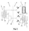
- Figure 3 shows a diagram of the operation of the present invention according to a further embodiment with respect to fig.1 , which can operate also in summer mode and providing, in addition to said radiant heat exchanger 1, a forced cooling air flow heat exchanger 7, which can be used as an alternative to said radiant heat exchanger 1, thus allowing the apparatus to operate alternately in a mode heating or cooling the environment.
- the evaporator 31 acts as a condenser, namely the flowing direction of the fluid is reversed and the evaporator/condenser 31 receives the pressurized conduction fluid from the compressor 2, and by converting said conduction fluid from the gaseous state to the liquid state it transfers heat to the outdoor environment 4.
- Said forced cooling air flow heat exchanger 7 is composed of an evaporator 71 wherein the conduction fluid is converted from the liquid state to the gaseous state, absorbing heat, of heat exchange means 72 and of forced air flow generating means 73 which generate said forced air flow 74 and convey it through said evaporator 71 and/or said heat exchange means 72, cooling the air and then releasing it into the environment.
- Such forced cooling air flow heat exchanger 7 is connected in parallel to said radiant heat exchanger 1 and it can be activated or deactivated via valves V3, V4, V5, V6.
- valves V3 and V5 When valves V3 and V5 are opened, valves V4 and V6 are closed, as seen in figure by broken lines, said radiant heat exchanger 1 is activated, said forced cooling air flow heat exchanger 7 is deactivated and the system works in a heating mode.
- valves V4 and V6 are opened, valves V3 and V5 are closed, said forced cooling air flow heat exchanger 7 is activated, said radiant heat exchanger 1 is deactivated, the fluid reverses its direction, and the system operates in cooling mode.
- valves V3, V4, V5 and V6 can be replaced by a single, properly connected, four-way valve, which adjusts the flowing direction of the conduction fluid coming out from the compressor 2.
- Fig. 4 shows an embodiment of the apparatus of the present invention, according to which the heat exchangers are housed within a cabinet 8, and said cabinet 8 has a front recess 81 intended for housing said radiant heat exchanger 1, a surrounding air intake port 82 and a port 83 for releasing air into the environment, through which ports the surrounding air is withdrawn, heated or cooled, and realased into the environment, a forced air flow heat exchanger, not shown in the figure, being provided into the cabinet.
- Fig. 5 is a cross-section view of said embodiment of the apparatus of the present invention, according to which heat exchangers are housed within a cabinet 8.
- Said cabinet 8 has said front recess 81 intended for housing said radiant heat exchanger 1, said radiant heat exchanger 1 being composed of said condenser 11 and said radiant members 12, and moreover said radiant heat exchanger 1 being spaced from the walls of said recess 81 such that an air channel 84 is formed passing between said radiant heat exchanger 1 and said recess 81.
- Said air channel 84 is run by an air flow 18, heating the air that finally is released into the environment.
- Said cabinet 8 has also said surrounding air intake port 82, through which the surrounding air, by said forced air flow generating means 63, is withdrawn and conveyed through said heat exchanger 6, then released into the environment, after having been heated, through said port 83 for releasing air into the environment.
- heat exchanger 6 can be used as a refrigerator for generating a forced cooling air flow, instead of an heating one, to be used as an alternative to said radiant heat exchanger 1.
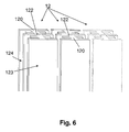
- Fig. 6 shows a front view of the radiant members 12, composed of parallelepiped shaped elongated elements 120 having such a thickness that a longitudinal hole 122 housing a condensation duct passes therethrough and having fins 121 arranged lenghtwise on the side surfaces.
- Said radiant members 12 that can be seen in the figure can be put one near the other, each one applied on a condensation duct, and at the front they can be provided with the flat surface 123 that can be seen in the figure.
- they can be rotated by 90° about the longitudinal axis passing by the longitudinal hole 122 such that the finned surface 124 is on the front thereof.
- Fig.7 shows three examples of possible sections of said radiant members 12.
- Section A is the same section shown in figure 6 , wherein fins 121 are lengthwise arranged on the parallelepiped shaped elongated element 120, the longitudinal hole 122 housing a condensation duct passes therethrough.
- Section B is substantially equal to section A but fins 121 are arranged in a different way.
- Section C shows a section of a radiant member composed of a substantially cylindrical element 125 through which said longitudinal hole 122 housing a condensation duct passes and it is composed of fins 121 which are lengthwise arranged on the shell surface and are radially oriented.
- the radiant member is composed of the condensation duct itself, which has such a shape that fins 121 are lentghwise arranged and radially oriented on the shell surface.
- Fig.8 shows a section view of a part of an embodiment of said radiant heat exchanger 1, which radiant heat exchanger 1 is composed of a condenser 11, which is composed in turn of a plurality of ducts 111, and of two radiant members 12 in the form of plates made of high thermal conductivity material, preferably of aluminium, in thermal contact with said ducts 111, which radiant plates 12 have fins 121 extending parallel each other throughout all the extension of the radiant plates 12, said fins 121 being intended for increasing the surface to volume ratio of said radiant members 12 and/or the surface for the thermal exchange with the surrounding air.
- Broken lines 86 and 87 are the back wall and the open front wall respectively of said recess of said cabinet wherein said radiant heat exchanger 1 is housed.
- Fig.9 shows the gaseous to liquid state conversion of the conduction fluid within the condensation ducts having a different diameter.
- the conduction fluid in the gaseous state transmits heat to the condenser itself, at the beginning it being converted to the liquid state along the inner walls of the ducts of said condenser; thus there is the situation where the conduction fluid is in its liquid state along the walls of the ducts but it is in its gaseous state yet at the core of said ducts.
- the figure shows two ducts E and F, having the same length x, with a diameter D and d respectively, where D > d; in both the ducts the liquid state 113 is already condensed on the duct walls and the gaseous state 112 is in the core, persisting for a predetermined length, before being completely condensed.
- Such predetermined length changes depending on the diameter and so on the surface/volume ratio of the duct, and it is L for duct E and 1 for duct F, where L > 1.
- the length of the duct portion where the gaseous state and the liquid state coexist is reduced, reducing the acoustic level of the generated gurgling noise; moreover a greater number of ducts is necessary, increasing the radiant surface the volume being the same, obtaining a better transfer of heat, and reducing the speed of the refrigerant fluid passing through the condensation ducts.
- the ratio between the diameter and the length of each condensation duct is comprised between 0.01 and 0.02, and is preferably about 0.015.
- each condensation duct is between 0.3 cm and 1 cm, in particular between 0.4 cm and 0.8 cm, and the length of each condensation duct is between 20 cm and 80 cm, in particular between 40 cm and 60 cm.
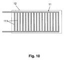
- Fig. 10 shows said embodiment of said radiant heat exchanger 1, where radiant members are as plates, and wherein the front radiant plate is omitted for clarity purposes and the rear radiant plate 12 is in thermal contact with the condenser 11, which is composed of a plurality of ducts 111.
Landscapes
- Engineering & Computer Science (AREA)
- Physics & Mathematics (AREA)
- General Engineering & Computer Science (AREA)
- Mechanical Engineering (AREA)
- Thermal Sciences (AREA)
- Chemical & Material Sciences (AREA)
- Combustion & Propulsion (AREA)
- Geometry (AREA)
- Life Sciences & Earth Sciences (AREA)
- Sustainable Development (AREA)
- Devices For Blowing Cold Air, Devices For Blowing Warm Air, And Means For Preventing Water Condensation In Air Conditioning Units (AREA)
- Heating, Cooling, Or Curing Plastics Or The Like In General (AREA)
- Central Heating Systems (AREA)
- Air Filters, Heat-Exchange Apparatuses, And Housings Of Air-Conditioning Units (AREA)
Claims (17)
- Strahlungsheizgerät bestehend aus einer Wärmepumpe, die
mit Hilfe eines Kompressors (2) eine leitende Flüssigkeit in gasförmigem Zustand zusammendrückt, wodurch sie in einem Kondensator (11) in den flüssigen Zustand umgewandelt wird, und anschließend gibt der Kondensator (11) die Wärme in die Umgebung (5) ab.
bestehend aus Wärmetauschern mit der Umgebung (5) durch Strahlung , die aus dem genannten Kondensator (11) mit mehrere Kondensationsröhren (111) und ein oder mehrere gerippte Strahlerelemente (12) aus einem Material mit einer Wärmeleitfähigkeit, die höher ist als 40 W x K-1x m-1 und vorzugsweise höher als 100 W x K-1x m-1, welche Strahlerelemente (12) auf die Kondensationsröhren (111) aufgebracht sind und sich in thermischem Kontakt mit dem Kondensator (11) befinden, um die Kondensationswärme vom Kondensator (11) zu den Strahlerelementen (12) zu übertragen,
dieses Gerät verfügt über einen zweiten Wärmeaustauscher (6, 7), der als Kondensator oder als Verdampfer fungieren kann, durch eine Inversion der Flussrichtung der Flüssigkeit, mit Mitteln für den Wärmeaustausch mit einem Luftstrom und Mitteln, die einen Zwangsluftstrom durch dieses Wärmeaustauschmittel des Verdampfers/Kondensators (61, 71) erzeugen,
dieser zweite Wärmeaustauscher (6, 7) ist parallel an den Strahlungswärmeaustauscher (1) angeschlossen und kann mit Hilfe der Ventile (V1, V2) aktiviert oder deaktiviert werden,
diese Wärmeaustauscher sind in einem Schrank (8) untergebracht, der:- einen umgebenden Luftansaugstutzen (82) und einen Stutzen (83) aufweist, um die Luft in die Umgebung (5) abzuleiten, welche Luft aus der Umgebung (5) flussaufwärts des zweiten Wärmeaustauschers (6, 7) entnommen wird und nach dem Wärmeaustausch mit diesem zweiten Wärmeaustauscher (6, 7) wieder in die Umgebung (5) abgegeben wirddadurch gekennzeichnet dass- auf einer Seite des Schrankes, vorzugsweise auf der Vorderseite, einen Einschnitt (81) vorgesehen ist, in dem der Strahlungswärmeaustauscher untergebracht ist, so dass dieser Strahlungswärmeaustauscher sich im Wesentlichen in diesem Schrank(8)raum befindet. - Ein Gerät gemäß Anspruch 1, dadurch gekennzeichnet dass der Strahlungswärmeaustauscher aus einem Kondensator (11) besteht, der mit einem Anschlussstück verbunden ist, das die leitende Flüssigkeit im gasförmigen Zustand liefert und in dessen Kondensationsröhren (111) die genannte leitende Flüssigkeit vom gasförmigen Zustand in den flüssigen Zustand umgewandelt wird, wobei Kondensationswärme übertragen wird.
- Gerät gemäß einer oder mehrerer der vorhergehenden Ansprüche, dadurch gekennzeichnet dass jeder der besagten Strahlerelemente (12) mit einer Durchgangsbohrung versehen ist, um mindestens eine Kondensationsröhre (111) darin aufzunehmen und ist in thermischen Kontakt mi diesen.
- Ein Gerät gemäß einem oder mehrerer der vorhergehenden Ansprüche, dadurch gekennzeichnet dass diese Kondensationsröhren (111) parallel angeschlossen sind und die Manteloberfläche dieser Kondensationsröhren (111) sind entlang einer tangentialen Hüllfläche oder entlang von zwei tangentialen Hüllflächen, auf den diametral gegenüberliegenden Seiten der Manteloberflächen der Kondensationsröhren (111) in Bezug auf die zentrale Längsachse der Kondensationsröhren (111) angeordnet und die Strahlerelemente (12) bestehen aus ein oder zwei Strahlerplatten (12), von der sich jede entlang der Hüllfläche erstreckt welche tangential zu den Mantelflächen der Kondensationsröhren (111) ist.
- Gerät gemäß Anspruch 1 oder 2, dadurch gekennzeichnet dass die Kondensationsröhren (111) nahe nebeneinander in einem vorgegebenen Abstand voneinander und entlang einer flachen oder gekrümmten Fläche entsprechend mindestens einer Krümmungsachse angeordnet sind, wobei die Strahlerplatte (12) flach bzw. gekrümmt ist.
- Gerät gemäß einem oder mehrerer der vorhergehenden Ansprüche, dadurch gekennzeichnet dass es zwei parallele Strahlerplatten (12) mit den dazwischengefügten Kondensationsröhren (111) aufweist, die in Kontakt mit jeder der beiden Platten (12) sind.
- Gerät gemäß einem oder mehrerer der vorhergehenden Ansprüche, dadurch gekennzeichnet dass der Durchmesser, die Länge und die Anzahl der Kondensationsröhren (111) einerseits in Bezug auf die Wärmeübertragung und auf die Kondensation vom gasförmigen Zustand in den flüssigen Zustand der leitenden Flüssigkeit und andererseits in Bezug auf die Reduzierung der akustischen Höhe des Glucksens, das durch die Umwandlung des Zustandes erzeugt wird, optimiert sind.
- Gerät gemäß einem oder mehrerer der vorhergehenden Ansprüche, dadurch gekennzeichnet dass das Verhältnis zwischen dem Durchmesser und der Länge jeder Kondensationsröhre (111) zwischen 0,01 und 0.02 liegt und vorzugweise 0,015 ist.
- Gerät gemäß einem oder mehrerer der vorhergehenden Ansprüche, in dem der besagte Strahlungswärmeaustauscher in einem Abstand von den Wänden des Einschnittes (81) angeordnet ist, so dass ein Luftkanal zwischen dem Strahlungswärmeaustauscher und dem Einschnitt (81) gebildet wird.
- Gerät gemäß einem oder mehrerer der vorhergehenden Ansprüche, dadurch gekennzeichnet dass die Strahlungselemente (12) aus Aluminium bestehen und eine gerippte Oberfläche haben, so dass das Verhältnis Oberfläche gegen Volumen der Strahlungselemente (12) bzw. die Oberfläche für den Wärmeaustausch mit der Umgebungsluft erhöht wird.
- Gerät gemäß einem oder mehrerer der vorhergehenden Ansprüche, dadurch gekennzeichnet dass besagte Mittel zur Erzeugung eines Zwangsluftstroms der Kühlluft werden als Alternative zu dem Mittel für den Wärmeaustausch mit der Umgebung (5) durch Strahlung bzw. durch einen Zwangsluftstrom betrieben.
- Gerät gemäß einem oder mehrerer der vorhergehenden Ansprüche, dadurch gekennzeichnet dass photovoltaische Mittel zur Erzeugung von Strom vorgesehen sind, welche solche Abmessungen aufweisen, dass die Oberfläche, die die elektrische Energie erzeugt und die der Sonne ausgesetzt ist, genug Strom garantiert, um das Wärmegerät sowohl im Falle eines Einzel-nutzers, als auch bei einem Zentralsystem selbständig zu speisen.
- Gerät gemäß einem oder mehrerer der vorhergehenden Ansprüche, dadurch gekennzeichnet dass, der Schrank (8) eine solche Größe und Form hat, dass er unter einem Fenster angeordnet werden kann.
- Gerät gemäß einem oder mehrerer der vorhergehenden Ansprüche, dadurch gekennzeichnet dass der Schrank (8) eine solche Größe und Form hat, dass er an einer Wand bzw. an der Decke aufgehängt werden kann.
- Gerät gemäß einem oder mehrerer der vorhergehenden Ansprüche, dadurch gekennzeichnet dass es die an der Wand montierbaren Wärmeaustauscher wie z.B. gebräuchliche Heizkörper aufweist, und dieses Mittel einen Zwangsheizungsfluss bzw. Kühlluftfluss erzeugt, das an einer Wand oder Decke oder alternativ entfernt von der Stelle angebracht ist, wo dieser Zwangsluftstrom hinausgelassen und in der Umgebung (5) verteilt wird, wobei dieser Zwangsluftstrom durch Röhren zu entsprechenden Öffnungen zum Ablassen und Verteilen in die Umgebung (5) zugeleitet wird.
- Gerät gemäß einem oder mehrerer der vorhergehenden Ansprüche, dadurch gekennzeichnet dass es aus einem handelsüblichen Klimagerät besteht.
- Verfahren zur Erwärmung durch Strahlung, dadurch gekennzeichnet dass folgende Schritten vorgesehen sind:- eine Leitmedium die im gasförmigen Zustand ist unter Druck setzen mit Hilfe eines Kompressors (2);- der unter Druck stehende Medium zu einem Kondensator (11) zuleiten;- Umwandeln des besagten Medium im Kondensator (11) aus dem gasförmigen in den flüssigen Zustand der besagte Kondensator (11) bestehend aus mehreren Kondensationsröhren (111), die entsprechend einer vorgegebenen Anordnung arrangiert sind und die mit einem Anschlussstück verbunden sind, das das gasförmige Leitmedium zufuehrt und in welchen Kondensationsröhren (111) dieser Leitmedium vom gasförmigen Zustand in den flüssigen Zustand umgewandelt wird und die Kondensationswärme dorthin übertragen wird;- Übertragen der Kondensationswärme in die Umgebung (5) durch Strahlung und Konvektion zwischen den Strahlungswärmeaustauschern und der Umgebung (5), die aus dem Kondensator (11) und mindestens einem gerippten Strahlungselement (12) aus einem Material mit einer Leitfähigkeit höher als 40 W x K-1x m-1 und vorzugsweise höher als 100 W x K-1x m-1 bestehen, wobei das Strahlungselement (12) auf mindestens eine der genannten Kondensationsröhren (111) aufgebracht werden kann und in thermischem Kontakt mit dem Kondensator (11) zur Übertragung der Kondensationswärme vom Kondensator (11) zum Strahlungselement oder den Strahlungselementen (12) ist, indem die Leitflüssigkeit im flüssigen Zustand zu einem Verdampfer (31) zur Wiederaufnahme des Kältekreislaufes strömt,- wobei ein zweiter Wärmeaustauscher (6, 7) durch Umkehr der Fließrichtung der Flüssigkeit als Kondensator oder als Verdampfer fungieren kann und Mittel zum Wärmeaustausch mit einem Luftstrom und Mittel zur Erzeugung eines Zwangsluft-stromes durch dieses Wärmeaustauschmittel des Kondensators/Verdampfers (61, 71) aufweist,der besagte zweite Wärmeaustauscher (6, 7) ist parallel am Strahlungswärmeaustauscher (1) angeschlossen und kann mit Hilfe der Ventile (V1, V2) aktiviert oder deaktiviert werden,
die besagten Wärmeaustauscher sind in einem Schrank (8) untergebracht, der:- auf einer seiner Seiten, vorzugweise auf der Vorderseite, einen Einschnitt (81) für die Unterbringung dieses Strahlungswärmeaustauscher aufweist, so dass der Strahlungswärmeaustauscher sich innerhalb dieses Schrankes (8) befindet,- einen umgebenden Luftansaugstutzen (82) und einen Stutzen (83) aufweist, um die Luft in die Umgebung (5) abzuleiten, welche Luft aus der Umgebung(5) flussaufwärts des zweiten Wärmeaustauscher (6, 7) entnommen wird und nach dem Wärmeaustausch mit diesem zweiten Wärmeaustauscher (6, 7) wieder in die Umgebung (5) abgegeben wird.
Applications Claiming Priority (2)
| Application Number | Priority Date | Filing Date | Title |
|---|---|---|---|
| ITGE2009A000054A IT1397613B1 (it) | 2009-07-16 | 2009-07-16 | Dispositivo di riscaldamento ad irraggiamento |
| PCT/EP2010/059963 WO2011006858A1 (en) | 2009-07-16 | 2010-07-12 | Radiation heating apparatus |
Publications (2)
| Publication Number | Publication Date |
|---|---|
| EP2454537A1 EP2454537A1 (de) | 2012-05-23 |
| EP2454537B1 true EP2454537B1 (de) | 2016-01-13 |
Family
ID=41614904
Family Applications (1)
| Application Number | Title | Priority Date | Filing Date |
|---|---|---|---|
| EP10732359.4A Revoked EP2454537B1 (de) | 2009-07-16 | 2010-07-12 | Strahlungsheizgerät |
Country Status (4)
| Country | Link |
|---|---|
| EP (1) | EP2454537B1 (de) |
| JP (1) | JP2012533048A (de) |
| IT (1) | IT1397613B1 (de) |
| WO (1) | WO2011006858A1 (de) |
Cited By (1)
| Publication number | Priority date | Publication date | Assignee | Title |
|---|---|---|---|---|
| CN108778793A (zh) * | 2016-03-11 | 2018-11-09 | 株式会社电装 | 控制车辆用空调装置的空调控制装置 |
Families Citing this family (4)
| Publication number | Priority date | Publication date | Assignee | Title |
|---|---|---|---|---|
| JP5544580B1 (ja) * | 2013-07-26 | 2014-07-09 | 株式会社 エコファクトリー | 空気調和装置及び空気調和装置の運転方法 |
| MY184976A (en) * | 2014-05-09 | 2021-04-30 | Eco Factory Co Ltd | Air conditioning system |
| CN106839497A (zh) * | 2017-02-07 | 2017-06-13 | 海信(山东)空调有限公司 | 一种换热循环系统及其控制方法以及空调 |
| CN113970164B (zh) * | 2020-07-24 | 2022-12-09 | 广东美的制冷设备有限公司 | 空调器及其辐射控制方法与装置、计算机可存储介质 |
Citations (41)
| Publication number | Priority date | Publication date | Assignee | Title |
|---|---|---|---|---|
| JPS5232152U (de) | 1975-08-28 | 1977-03-07 | ||
| JPS52141258U (de) | 1976-04-20 | 1977-10-26 | ||
| JPS5367352U (de) | 1976-11-09 | 1978-06-06 | ||
| JPS5396356U (de) | 1977-01-07 | 1978-08-05 | ||
| JPS558570A (en) | 1978-07-04 | 1980-01-22 | Matsushita Electric Ind Co Ltd | Air conditioner |
| JPS5818136Y2 (ja) | 1976-02-09 | 1983-04-12 | 松下電器産業株式会社 | 冷暖房装置 |
| JPS58221337A (ja) | 1982-06-18 | 1983-12-23 | Hitachi Ltd | ヒ−トポンプ式空気調和装置 |
| JPS62228844A (ja) | 1986-03-31 | 1987-10-07 | 株式会社東芝 | 空気調和機 |
| JPS6329025U (de) | 1986-08-11 | 1988-02-25 | ||
| EP0269282A2 (de) * | 1986-10-30 | 1988-06-01 | Kabushiki Kaisha Toshiba | Klimaanlage |
| JPS63188421A (ja) | 1987-01-30 | 1988-08-04 | Sumitomo Heavy Ind Ltd | 材料の任意温度抽出可能な冷却設備 |
| JPS63210575A (ja) | 1987-02-27 | 1988-09-01 | 株式会社東芝 | 空気調和機 |
| JPS63185023U (de) | 1987-05-21 | 1988-11-28 | ||
| JPS6419832A (en) | 1987-07-15 | 1989-01-23 | Nec Corp | Narrow band detector |
| JPS6458965A (en) | 1987-08-31 | 1989-03-06 | Toshiba Corp | Air conditioner with radiation panel |
| JPS6458968A (en) | 1987-08-31 | 1989-03-06 | Toshiba Corp | Air conditioner |
| JPH01172614U (de) | 1988-05-27 | 1989-12-07 | ||
| JPH0257830A (ja) | 1988-08-22 | 1990-02-27 | Toshiba Corp | 空気調和機 |
| JPH02259348A (ja) | 1988-12-26 | 1990-10-22 | Toshiba Audio Video Eng Corp | 空気調和装置 |
| JPH03127126A (ja) | 1989-10-13 | 1991-05-30 | Nec Corp | 情報処理装置 |
| JPH0357310U (de) | 1989-10-04 | 1991-06-03 | ||
| JPH03127123U (de) | 1990-03-30 | 1991-12-20 | ||
| JPH0436527A (ja) | 1990-05-30 | 1992-02-06 | Sanyo Electric Co Ltd | 熱交換ユニット |
| JPH0432434U (de) | 1990-07-16 | 1992-03-17 | ||
| JPH0436520U (de) | 1990-07-17 | 1992-03-26 | ||
| JPH04236073A (ja) | 1991-01-21 | 1992-08-25 | Matsushita Electric Ind Co Ltd | 空気調和装置 |
| JPH05133165A (ja) | 1991-11-14 | 1993-05-28 | Natl House Ind Co Ltd | 出窓空調装置 |
| JPH05152151A (ja) | 1991-11-29 | 1993-06-18 | Tokin Corp | 自動巻線装置 |
| JPH05280762A (ja) | 1992-03-30 | 1993-10-26 | Toshiba Corp | 輻射パネル付室内ユニット |
| JPH05346261A (ja) | 1991-04-18 | 1993-12-27 | Matsushita Electric Ind Co Ltd | 空気調和装置 |
| WO1994023257A1 (en) | 1993-03-29 | 1994-10-13 | Melanesia International Trust Company Limited | Heat exchanger assembly |
| JPH07127994A (ja) | 1993-11-05 | 1995-05-19 | Toshiba Corp | 空気調和機の輻射パネル |
| JPH07190400A (ja) | 1993-12-27 | 1995-07-28 | Toshiba Corp | 空気調和装置 |
| US5493155A (en) | 1991-04-22 | 1996-02-20 | Sharp Kabushiki Kaisha | Electric power supply system |
| JPH09152146A (ja) | 1995-11-30 | 1997-06-10 | Sanyo Electric Co Ltd | 輻射式空調装置及びそれに用いられる輻射パネル |
| EP0789216A2 (de) | 1995-09-14 | 1997-08-13 | Sanyo Electric Co. Ltd | Wärmetauscher mit gewellten Rippen und hiermit versehene Klimaanlage |
| JP2004132560A (ja) | 2002-10-08 | 2004-04-30 | Daikin Ind Ltd | 空気調和機 |
| JP2005016919A (ja) | 2003-06-30 | 2005-01-20 | Daikin Ind Ltd | 空気調和装置 |
| WO2006009339A1 (en) | 2004-07-23 | 2006-01-26 | Lg Electronics Inc. | Condenser of refrigerator |
| JP2006029705A (ja) | 2004-07-16 | 2006-02-02 | Daikin Ind Ltd | 空気調和装置 |
| EP2040009A1 (de) | 2006-07-06 | 2009-03-25 | Daikin Industries, Ltd. | Klimaanlage |
Family Cites Families (5)
| Publication number | Priority date | Publication date | Assignee | Title |
|---|---|---|---|---|
| GB355050A (en) * | 1930-11-11 | 1931-08-20 | Clement Henry Stevens | Improvements in radiators for cooling or heating fluids |
| NL8202860A (nl) * | 1982-07-15 | 1984-02-01 | Burnham Europa Bv | Warmtewisselaar. |
| EP0183211A3 (de) * | 1984-11-23 | 1986-10-29 | Norsk Hydro A/S | Modulwärmetauscher und Verfahren zu seiner Herstellung |
| GB9012080D0 (en) * | 1990-05-31 | 1990-07-18 | Servotomic Ltd | Improvements in or relating to heat exchangers |
| CN101158525A (zh) * | 2007-09-11 | 2008-04-09 | 东莞高宝铝材制品厂有限公司 | 一种一体成型翅片式铝合金复合材料无缝微孔散热片的冷凝器和散热网 |
-
2009
- 2009-07-16 IT ITGE2009A000054A patent/IT1397613B1/it active
-
2010
- 2010-07-12 JP JP2012519988A patent/JP2012533048A/ja not_active Withdrawn
- 2010-07-12 WO PCT/EP2010/059963 patent/WO2011006858A1/en active Application Filing
- 2010-07-12 EP EP10732359.4A patent/EP2454537B1/de not_active Revoked
Patent Citations (41)
| Publication number | Priority date | Publication date | Assignee | Title |
|---|---|---|---|---|
| JPS5232152U (de) | 1975-08-28 | 1977-03-07 | ||
| JPS5818136Y2 (ja) | 1976-02-09 | 1983-04-12 | 松下電器産業株式会社 | 冷暖房装置 |
| JPS52141258U (de) | 1976-04-20 | 1977-10-26 | ||
| JPS5367352U (de) | 1976-11-09 | 1978-06-06 | ||
| JPS5396356U (de) | 1977-01-07 | 1978-08-05 | ||
| JPS558570A (en) | 1978-07-04 | 1980-01-22 | Matsushita Electric Ind Co Ltd | Air conditioner |
| JPS58221337A (ja) | 1982-06-18 | 1983-12-23 | Hitachi Ltd | ヒ−トポンプ式空気調和装置 |
| JPS62228844A (ja) | 1986-03-31 | 1987-10-07 | 株式会社東芝 | 空気調和機 |
| JPS6329025U (de) | 1986-08-11 | 1988-02-25 | ||
| EP0269282A2 (de) * | 1986-10-30 | 1988-06-01 | Kabushiki Kaisha Toshiba | Klimaanlage |
| JPS63188421A (ja) | 1987-01-30 | 1988-08-04 | Sumitomo Heavy Ind Ltd | 材料の任意温度抽出可能な冷却設備 |
| JPS63210575A (ja) | 1987-02-27 | 1988-09-01 | 株式会社東芝 | 空気調和機 |
| JPS63185023U (de) | 1987-05-21 | 1988-11-28 | ||
| JPS6419832A (en) | 1987-07-15 | 1989-01-23 | Nec Corp | Narrow band detector |
| JPS6458965A (en) | 1987-08-31 | 1989-03-06 | Toshiba Corp | Air conditioner with radiation panel |
| JPS6458968A (en) | 1987-08-31 | 1989-03-06 | Toshiba Corp | Air conditioner |
| JPH01172614U (de) | 1988-05-27 | 1989-12-07 | ||
| JPH0257830A (ja) | 1988-08-22 | 1990-02-27 | Toshiba Corp | 空気調和機 |
| JPH02259348A (ja) | 1988-12-26 | 1990-10-22 | Toshiba Audio Video Eng Corp | 空気調和装置 |
| JPH0357310U (de) | 1989-10-04 | 1991-06-03 | ||
| JPH03127126A (ja) | 1989-10-13 | 1991-05-30 | Nec Corp | 情報処理装置 |
| JPH03127123U (de) | 1990-03-30 | 1991-12-20 | ||
| JPH0436527A (ja) | 1990-05-30 | 1992-02-06 | Sanyo Electric Co Ltd | 熱交換ユニット |
| JPH0432434U (de) | 1990-07-16 | 1992-03-17 | ||
| JPH0436520U (de) | 1990-07-17 | 1992-03-26 | ||
| JPH04236073A (ja) | 1991-01-21 | 1992-08-25 | Matsushita Electric Ind Co Ltd | 空気調和装置 |
| JPH05346261A (ja) | 1991-04-18 | 1993-12-27 | Matsushita Electric Ind Co Ltd | 空気調和装置 |
| US5493155A (en) | 1991-04-22 | 1996-02-20 | Sharp Kabushiki Kaisha | Electric power supply system |
| JPH05133165A (ja) | 1991-11-14 | 1993-05-28 | Natl House Ind Co Ltd | 出窓空調装置 |
| JPH05152151A (ja) | 1991-11-29 | 1993-06-18 | Tokin Corp | 自動巻線装置 |
| JPH05280762A (ja) | 1992-03-30 | 1993-10-26 | Toshiba Corp | 輻射パネル付室内ユニット |
| WO1994023257A1 (en) | 1993-03-29 | 1994-10-13 | Melanesia International Trust Company Limited | Heat exchanger assembly |
| JPH07127994A (ja) | 1993-11-05 | 1995-05-19 | Toshiba Corp | 空気調和機の輻射パネル |
| JPH07190400A (ja) | 1993-12-27 | 1995-07-28 | Toshiba Corp | 空気調和装置 |
| EP0789216A2 (de) | 1995-09-14 | 1997-08-13 | Sanyo Electric Co. Ltd | Wärmetauscher mit gewellten Rippen und hiermit versehene Klimaanlage |
| JPH09152146A (ja) | 1995-11-30 | 1997-06-10 | Sanyo Electric Co Ltd | 輻射式空調装置及びそれに用いられる輻射パネル |
| JP2004132560A (ja) | 2002-10-08 | 2004-04-30 | Daikin Ind Ltd | 空気調和機 |
| JP2005016919A (ja) | 2003-06-30 | 2005-01-20 | Daikin Ind Ltd | 空気調和装置 |
| JP2006029705A (ja) | 2004-07-16 | 2006-02-02 | Daikin Ind Ltd | 空気調和装置 |
| WO2006009339A1 (en) | 2004-07-23 | 2006-01-26 | Lg Electronics Inc. | Condenser of refrigerator |
| EP2040009A1 (de) | 2006-07-06 | 2009-03-25 | Daikin Industries, Ltd. | Klimaanlage |
Cited By (2)
| Publication number | Priority date | Publication date | Assignee | Title |
|---|---|---|---|---|
| CN108778793A (zh) * | 2016-03-11 | 2018-11-09 | 株式会社电装 | 控制车辆用空调装置的空调控制装置 |
| CN108778793B (zh) * | 2016-03-11 | 2021-12-14 | 株式会社电装 | 控制车辆用空调装置的空调控制装置 |
Also Published As
| Publication number | Publication date |
|---|---|
| JP2012533048A (ja) | 2012-12-20 |
| WO2011006858A1 (en) | 2011-01-20 |
| EP2454537A1 (de) | 2012-05-23 |
| IT1397613B1 (it) | 2013-01-18 |
| ITGE20090054A1 (it) | 2011-01-17 |
Similar Documents
| Publication | Publication Date | Title |
|---|---|---|
| EP2454537B1 (de) | Strahlungsheizgerät | |
| CN203704150U (zh) | 一种双系统节能的机柜散热空调 | |
| WO2020029582A1 (zh) | 空气源热泵空调器用无风机且内置蓄热介质的室内换热器 | |
| CN101959388A (zh) | 一种带制冷剂循环换热的电信机柜及其冷却方法 | |
| CN107548263B (zh) | 高热流密度机柜散热冷却方法及其复合换热器 | |
| US11441789B2 (en) | Convection/radiation air conditioning terminal and air conditioning system | |
| CN201074879Y (zh) | 自然对流换热空调室内机 | |
| CN202282922U (zh) | 一种节能散热机柜 | |
| CN102252385A (zh) | 双回路空调系统 | |
| CN201509386U (zh) | 一种带制冷剂循环换热的电信机柜 | |
| CN101806478A (zh) | 交叉风道半导体热电制冷空调器 | |
| CN205812621U (zh) | 高热流密度机柜复合换热器 | |
| CN104266411B (zh) | 一种复合制冷系统用组合式风冷换热总成 | |
| CN215295145U (zh) | 散热器和空调器 | |
| CN104613799A (zh) | 具有板式微热管的自然对流式暖气片 | |
| CN201621996U (zh) | 一种热管 | |
| CN204084954U (zh) | 一种复合制冷系统用组合式风冷换热总成 | |
| CN216347154U (zh) | 一种内外双循环半导体冷藏暖藏箱 | |
| CN103954073A (zh) | 热管辐射立式采暖/制冷系统和方法 | |
| CN201622006U (zh) | 一种热管散热器 | |
| CN201032438Y (zh) | 机房用空气热交换装置 | |
| CN201100792Y (zh) | 多功能型翅片管式冷凝器 | |
| CN216716399U (zh) | 空调器 | |
| CN105485969B (zh) | 换热装置及具有该换热装置的半导体制冷冰箱 | |
| CN217302982U (zh) | 一种空调系统 |
Legal Events
| Date | Code | Title | Description |
|---|---|---|---|
| PUAI | Public reference made under article 153(3) epc to a published international application that has entered the european phase |
Free format text: ORIGINAL CODE: 0009012 |
|
| 17P | Request for examination filed |
Effective date: 20120116 |
|
| AK | Designated contracting states |
Kind code of ref document: A1 Designated state(s): AL AT BE BG CH CY CZ DE DK EE ES FI FR GB GR HR HU IE IS IT LI LT LU LV MC MK MT NL NO PL PT RO SE SI SK SM TR |
|
| DAX | Request for extension of the european patent (deleted) | ||
| TPAC | Observations filed by third parties |
Free format text: ORIGINAL CODE: EPIDOSNTIPA |
|
| 17Q | First examination report despatched |
Effective date: 20131118 |
|
| GRAP | Despatch of communication of intention to grant a patent |
Free format text: ORIGINAL CODE: EPIDOSNIGR1 |
|
| INTG | Intention to grant announced |
Effective date: 20150714 |
|
| GRAS | Grant fee paid |
Free format text: ORIGINAL CODE: EPIDOSNIGR3 |
|
| GRAA | (expected) grant |
Free format text: ORIGINAL CODE: 0009210 |
|
| STAA | Information on the status of an ep patent application or granted ep patent |
Free format text: STATUS: THE PATENT HAS BEEN GRANTED |
|
| AK | Designated contracting states |
Kind code of ref document: B1 Designated state(s): AL AT BE BG CH CY CZ DE DK EE ES FI FR GB GR HR HU IE IS IT LI LT LU LV MC MK MT NL NO PL PT RO SE SI SK SM TR |
|
| REG | Reference to a national code |
Ref country code: GB Ref legal event code: FG4D |
|
| REG | Reference to a national code |
Ref country code: CH Ref legal event code: EP |
|
| REG | Reference to a national code |
Ref country code: IE Ref legal event code: FG4D |
|
| REG | Reference to a national code |
Ref country code: AT Ref legal event code: REF Ref document number: 770797 Country of ref document: AT Kind code of ref document: T Effective date: 20160215 |
|
| REG | Reference to a national code |
Ref country code: DE Ref legal event code: R096 Ref document number: 602010030160 Country of ref document: DE |
|
| REG | Reference to a national code |
Ref country code: LT Ref legal event code: MG4D |
|
| REG | Reference to a national code |
Ref country code: NL Ref legal event code: MP Effective date: 20160113 |
|
| REG | Reference to a national code |
Ref country code: AT Ref legal event code: MK05 Ref document number: 770797 Country of ref document: AT Kind code of ref document: T Effective date: 20160113 |
|
| PG25 | Lapsed in a contracting state [announced via postgrant information from national office to epo] |
Ref country code: NL Free format text: LAPSE BECAUSE OF FAILURE TO SUBMIT A TRANSLATION OF THE DESCRIPTION OR TO PAY THE FEE WITHIN THE PRESCRIBED TIME-LIMIT Effective date: 20160113 |
|
| REG | Reference to a national code |
Ref country code: FR Ref legal event code: PLFP Year of fee payment: 7 |
|
| PG25 | Lapsed in a contracting state [announced via postgrant information from national office to epo] |
Ref country code: ES Free format text: LAPSE BECAUSE OF FAILURE TO SUBMIT A TRANSLATION OF THE DESCRIPTION OR TO PAY THE FEE WITHIN THE PRESCRIBED TIME-LIMIT Effective date: 20160113 Ref country code: GR Free format text: LAPSE BECAUSE OF FAILURE TO SUBMIT A TRANSLATION OF THE DESCRIPTION OR TO PAY THE FEE WITHIN THE PRESCRIBED TIME-LIMIT Effective date: 20160414 Ref country code: HR Free format text: LAPSE BECAUSE OF FAILURE TO SUBMIT A TRANSLATION OF THE DESCRIPTION OR TO PAY THE FEE WITHIN THE PRESCRIBED TIME-LIMIT Effective date: 20160113 Ref country code: NO Free format text: LAPSE BECAUSE OF FAILURE TO SUBMIT A TRANSLATION OF THE DESCRIPTION OR TO PAY THE FEE WITHIN THE PRESCRIBED TIME-LIMIT Effective date: 20160413 Ref country code: FI Free format text: LAPSE BECAUSE OF FAILURE TO SUBMIT A TRANSLATION OF THE DESCRIPTION OR TO PAY THE FEE WITHIN THE PRESCRIBED TIME-LIMIT Effective date: 20160113 |
|
| PG25 | Lapsed in a contracting state [announced via postgrant information from national office to epo] |
Ref country code: IS Free format text: LAPSE BECAUSE OF FAILURE TO SUBMIT A TRANSLATION OF THE DESCRIPTION OR TO PAY THE FEE WITHIN THE PRESCRIBED TIME-LIMIT Effective date: 20160513 Ref country code: AT Free format text: LAPSE BECAUSE OF FAILURE TO SUBMIT A TRANSLATION OF THE DESCRIPTION OR TO PAY THE FEE WITHIN THE PRESCRIBED TIME-LIMIT Effective date: 20160113 Ref country code: PL Free format text: LAPSE BECAUSE OF FAILURE TO SUBMIT A TRANSLATION OF THE DESCRIPTION OR TO PAY THE FEE WITHIN THE PRESCRIBED TIME-LIMIT Effective date: 20160113 Ref country code: LV Free format text: LAPSE BECAUSE OF FAILURE TO SUBMIT A TRANSLATION OF THE DESCRIPTION OR TO PAY THE FEE WITHIN THE PRESCRIBED TIME-LIMIT Effective date: 20160113 Ref country code: PT Free format text: LAPSE BECAUSE OF FAILURE TO SUBMIT A TRANSLATION OF THE DESCRIPTION OR TO PAY THE FEE WITHIN THE PRESCRIBED TIME-LIMIT Effective date: 20160513 Ref country code: LT Free format text: LAPSE BECAUSE OF FAILURE TO SUBMIT A TRANSLATION OF THE DESCRIPTION OR TO PAY THE FEE WITHIN THE PRESCRIBED TIME-LIMIT Effective date: 20160113 Ref country code: SE Free format text: LAPSE BECAUSE OF FAILURE TO SUBMIT A TRANSLATION OF THE DESCRIPTION OR TO PAY THE FEE WITHIN THE PRESCRIBED TIME-LIMIT Effective date: 20160113 |
|
| PGFP | Annual fee paid to national office [announced via postgrant information from national office to epo] |
Ref country code: LU Payment date: 20160728 Year of fee payment: 7 |
|
| REG | Reference to a national code |
Ref country code: DE Ref legal event code: R026 Ref document number: 602010030160 Country of ref document: DE |
|
| PLBI | Opposition filed |
Free format text: ORIGINAL CODE: 0009260 |
|
| PG25 | Lapsed in a contracting state [announced via postgrant information from national office to epo] |
Ref country code: DK Free format text: LAPSE BECAUSE OF FAILURE TO SUBMIT A TRANSLATION OF THE DESCRIPTION OR TO PAY THE FEE WITHIN THE PRESCRIBED TIME-LIMIT Effective date: 20160113 Ref country code: EE Free format text: LAPSE BECAUSE OF FAILURE TO SUBMIT A TRANSLATION OF THE DESCRIPTION OR TO PAY THE FEE WITHIN THE PRESCRIBED TIME-LIMIT Effective date: 20160113 |
|
| PGFP | Annual fee paid to national office [announced via postgrant information from national office to epo] |
Ref country code: IE Payment date: 20160726 Year of fee payment: 7 Ref country code: CH Payment date: 20160728 Year of fee payment: 7 Ref country code: MC Payment date: 20160729 Year of fee payment: 7 |
|
| 26 | Opposition filed |
Opponent name: DAIKIN AIR CONDITIONING ITALY S.P.A Effective date: 20161005 |
|
| PLAX | Notice of opposition and request to file observation + time limit sent |
Free format text: ORIGINAL CODE: EPIDOSNOBS2 |
|
| PG25 | Lapsed in a contracting state [announced via postgrant information from national office to epo] |
Ref country code: CZ Free format text: LAPSE BECAUSE OF FAILURE TO SUBMIT A TRANSLATION OF THE DESCRIPTION OR TO PAY THE FEE WITHIN THE PRESCRIBED TIME-LIMIT Effective date: 20160113 Ref country code: SK Free format text: LAPSE BECAUSE OF FAILURE TO SUBMIT A TRANSLATION OF THE DESCRIPTION OR TO PAY THE FEE WITHIN THE PRESCRIBED TIME-LIMIT Effective date: 20160113 Ref country code: RO Free format text: LAPSE BECAUSE OF FAILURE TO SUBMIT A TRANSLATION OF THE DESCRIPTION OR TO PAY THE FEE WITHIN THE PRESCRIBED TIME-LIMIT Effective date: 20160113 Ref country code: SM Free format text: LAPSE BECAUSE OF FAILURE TO SUBMIT A TRANSLATION OF THE DESCRIPTION OR TO PAY THE FEE WITHIN THE PRESCRIBED TIME-LIMIT Effective date: 20160113 |
|
| PG25 | Lapsed in a contracting state [announced via postgrant information from national office to epo] |
Ref country code: BE Free format text: LAPSE BECAUSE OF FAILURE TO SUBMIT A TRANSLATION OF THE DESCRIPTION OR TO PAY THE FEE WITHIN THE PRESCRIBED TIME-LIMIT Effective date: 20160113 |
|
| PLAB | Opposition data, opponent's data or that of the opponent's representative modified |
Free format text: ORIGINAL CODE: 0009299OPPO |
|
| R26 | Opposition filed (corrected) |
Opponent name: DAIKIN AIR CONDITIONING ITALY S.P.A Effective date: 20161005 |
|
| PG25 | Lapsed in a contracting state [announced via postgrant information from national office to epo] |
Ref country code: SI Free format text: LAPSE BECAUSE OF FAILURE TO SUBMIT A TRANSLATION OF THE DESCRIPTION OR TO PAY THE FEE WITHIN THE PRESCRIBED TIME-LIMIT Effective date: 20160113 Ref country code: BG Free format text: LAPSE BECAUSE OF FAILURE TO SUBMIT A TRANSLATION OF THE DESCRIPTION OR TO PAY THE FEE WITHIN THE PRESCRIBED TIME-LIMIT Effective date: 20160413 |
|
| PLBB | Reply of patent proprietor to notice(s) of opposition received |
Free format text: ORIGINAL CODE: EPIDOSNOBS3 |
|
| REG | Reference to a national code |
Ref country code: FR Ref legal event code: PLFP Year of fee payment: 8 |
|
| REG | Reference to a national code |
Ref country code: CH Ref legal event code: PL |
|
| REG | Reference to a national code |
Ref country code: IE Ref legal event code: MM4A |
|
| PG25 | Lapsed in a contracting state [announced via postgrant information from national office to epo] |
Ref country code: IE Free format text: LAPSE BECAUSE OF NON-PAYMENT OF DUE FEES Effective date: 20170712 Ref country code: LI Free format text: LAPSE BECAUSE OF NON-PAYMENT OF DUE FEES Effective date: 20170731 Ref country code: CH Free format text: LAPSE BECAUSE OF NON-PAYMENT OF DUE FEES Effective date: 20170731 |
|
| PG25 | Lapsed in a contracting state [announced via postgrant information from national office to epo] |
Ref country code: HU Free format text: LAPSE BECAUSE OF FAILURE TO SUBMIT A TRANSLATION OF THE DESCRIPTION OR TO PAY THE FEE WITHIN THE PRESCRIBED TIME-LIMIT; INVALID AB INITIO Effective date: 20100712 Ref country code: CY Free format text: LAPSE BECAUSE OF FAILURE TO SUBMIT A TRANSLATION OF THE DESCRIPTION OR TO PAY THE FEE WITHIN THE PRESCRIBED TIME-LIMIT Effective date: 20160113 |
|
| PG25 | Lapsed in a contracting state [announced via postgrant information from national office to epo] |
Ref country code: MK Free format text: LAPSE BECAUSE OF FAILURE TO SUBMIT A TRANSLATION OF THE DESCRIPTION OR TO PAY THE FEE WITHIN THE PRESCRIBED TIME-LIMIT Effective date: 20160113 Ref country code: MT Free format text: LAPSE BECAUSE OF NON-PAYMENT OF DUE FEES Effective date: 20160731 Ref country code: TR Free format text: LAPSE BECAUSE OF FAILURE TO SUBMIT A TRANSLATION OF THE DESCRIPTION OR TO PAY THE FEE WITHIN THE PRESCRIBED TIME-LIMIT Effective date: 20160113 Ref country code: LU Free format text: LAPSE BECAUSE OF NON-PAYMENT OF DUE FEES Effective date: 20170712 |
|
| RDAF | Communication despatched that patent is revoked |
Free format text: ORIGINAL CODE: EPIDOSNREV1 |
|
| STAA | Information on the status of an ep patent application or granted ep patent |
Free format text: STATUS: THE PATENT HAS BEEN GRANTED |
|
| REG | Reference to a national code |
Ref country code: FR Ref legal event code: PLFP Year of fee payment: 9 |
|
| APBM | Appeal reference recorded |
Free format text: ORIGINAL CODE: EPIDOSNREFNO |
|
| APBP | Date of receipt of notice of appeal recorded |
Free format text: ORIGINAL CODE: EPIDOSNNOA2O |
|
| APAH | Appeal reference modified |
Free format text: ORIGINAL CODE: EPIDOSCREFNO |
|
| PG25 | Lapsed in a contracting state [announced via postgrant information from national office to epo] |
Ref country code: AL Free format text: LAPSE BECAUSE OF FAILURE TO SUBMIT A TRANSLATION OF THE DESCRIPTION OR TO PAY THE FEE WITHIN THE PRESCRIBED TIME-LIMIT Effective date: 20160113 |
|
| APBQ | Date of receipt of statement of grounds of appeal recorded |
Free format text: ORIGINAL CODE: EPIDOSNNOA3O |
|
| PG25 | Lapsed in a contracting state [announced via postgrant information from national office to epo] |
Ref country code: MC Free format text: LAPSE BECAUSE OF NON-PAYMENT OF DUE FEES Effective date: 20170731 |
|
| PGFP | Annual fee paid to national office [announced via postgrant information from national office to epo] |
Ref country code: FR Payment date: 20190715 Year of fee payment: 10 Ref country code: IT Payment date: 20190726 Year of fee payment: 10 Ref country code: DE Payment date: 20190725 Year of fee payment: 10 |
|
| PGFP | Annual fee paid to national office [announced via postgrant information from national office to epo] |
Ref country code: GB Payment date: 20190716 Year of fee payment: 10 |
|
| REG | Reference to a national code |
Ref country code: DE Ref legal event code: R119 Ref document number: 602010030160 Country of ref document: DE |
|
| GBPC | Gb: european patent ceased through non-payment of renewal fee |
Effective date: 20200712 |
|
| PG25 | Lapsed in a contracting state [announced via postgrant information from national office to epo] |
Ref country code: FR Free format text: LAPSE BECAUSE OF NON-PAYMENT OF DUE FEES Effective date: 20200731 Ref country code: IT Free format text: LAPSE BECAUSE OF NON-PAYMENT OF DUE FEES Effective date: 20210131 |
|
| PG25 | Lapsed in a contracting state [announced via postgrant information from national office to epo] |
Ref country code: GB Free format text: LAPSE BECAUSE OF NON-PAYMENT OF DUE FEES Effective date: 20200712 |
|
| APBY | Invitation to file observations in appeal sent |
Free format text: ORIGINAL CODE: EPIDOSNOBA2O |
|
| PG25 | Lapsed in a contracting state [announced via postgrant information from national office to epo] |
Ref country code: DE Free format text: LAPSE BECAUSE OF NON-PAYMENT OF DUE FEES Effective date: 20210202 |
|
| APBU | Appeal procedure closed |
Free format text: ORIGINAL CODE: EPIDOSNNOA9O |
|
| REG | Reference to a national code |
Ref country code: DE Ref legal event code: R103 Ref document number: 602010030160 Country of ref document: DE Ref country code: DE Ref legal event code: R064 Ref document number: 602010030160 Country of ref document: DE |
|
| RDAG | Patent revoked |
Free format text: ORIGINAL CODE: 0009271 |
|
| STAA | Information on the status of an ep patent application or granted ep patent |
Free format text: STATUS: PATENT REVOKED |
|
| PG25 | Lapsed in a contracting state [announced via postgrant information from national office to epo] |
Ref country code: IT Free format text: LAPSE BECAUSE OF NON-PAYMENT OF DUE FEES Effective date: 20200712 |
|
| REG | Reference to a national code |
Ref country code: FI Ref legal event code: MGE |
|
| 27W | Patent revoked |
Effective date: 20210924 |