EP2454514B1 - Steckkupplung - Google Patents
Steckkupplung Download PDFInfo
- Publication number
- EP2454514B1 EP2454514B1 EP10730375.2A EP10730375A EP2454514B1 EP 2454514 B1 EP2454514 B1 EP 2454514B1 EP 10730375 A EP10730375 A EP 10730375A EP 2454514 B1 EP2454514 B1 EP 2454514B1
- Authority
- EP
- European Patent Office
- Prior art keywords
- latching
- coupling
- plug
- arm
- locking
- Prior art date
- Legal status (The legal status is an assumption and is not a legal conclusion. Google has not performed a legal analysis and makes no representation as to the accuracy of the status listed.)
- Active
Links
- 230000008878 coupling Effects 0.000 claims description 202
- 238000010168 coupling process Methods 0.000 claims description 202
- 238000005859 coupling reaction Methods 0.000 claims description 202
- 239000002184 metal Substances 0.000 claims description 3
- 230000013011 mating Effects 0.000 claims 4
- 238000002347 injection Methods 0.000 claims 1
- 239000007924 injection Substances 0.000 claims 1
- 238000006073 displacement reaction Methods 0.000 description 33
- 210000002105 tongue Anatomy 0.000 description 8
- 238000003825 pressing Methods 0.000 description 7
- 239000012530 fluid Substances 0.000 description 6
- 230000003993 interaction Effects 0.000 description 4
- 238000007789 sealing Methods 0.000 description 3
- 230000005489 elastic deformation Effects 0.000 description 2
- 210000005224 forefinger Anatomy 0.000 description 2
- 238000004519 manufacturing process Methods 0.000 description 2
- 239000000463 material Substances 0.000 description 2
- 230000002093 peripheral effect Effects 0.000 description 2
- 210000003813 thumb Anatomy 0.000 description 2
- 210000000078 claw Anatomy 0.000 description 1
- 230000001419 dependent effect Effects 0.000 description 1
- 230000000694 effects Effects 0.000 description 1
- 239000013013 elastic material Substances 0.000 description 1
- 238000005516 engineering process Methods 0.000 description 1
- 230000008014 freezing Effects 0.000 description 1
- 238000007710 freezing Methods 0.000 description 1
- 238000001746 injection moulding Methods 0.000 description 1
- 238000009434 installation Methods 0.000 description 1
- 238000000034 method Methods 0.000 description 1
- 230000000284 resting effect Effects 0.000 description 1
- 125000006850 spacer group Chemical group 0.000 description 1
- 238000009827 uniform distribution Methods 0.000 description 1
Images


Classifications
-
- F—MECHANICAL ENGINEERING; LIGHTING; HEATING; WEAPONS; BLASTING
- F16—ENGINEERING ELEMENTS AND UNITS; GENERAL MEASURES FOR PRODUCING AND MAINTAINING EFFECTIVE FUNCTIONING OF MACHINES OR INSTALLATIONS; THERMAL INSULATION IN GENERAL
- F16L—PIPES; JOINTS OR FITTINGS FOR PIPES; SUPPORTS FOR PIPES, CABLES OR PROTECTIVE TUBING; MEANS FOR THERMAL INSULATION IN GENERAL
- F16L37/00—Couplings of the quick-acting type
- F16L37/08—Couplings of the quick-acting type in which the connection between abutting or axially overlapping ends is maintained by locking members
- F16L37/084—Couplings of the quick-acting type in which the connection between abutting or axially overlapping ends is maintained by locking members combined with automatic locking
- F16L37/098—Couplings of the quick-acting type in which the connection between abutting or axially overlapping ends is maintained by locking members combined with automatic locking by means of flexible hooks
- F16L37/0985—Couplings of the quick-acting type in which the connection between abutting or axially overlapping ends is maintained by locking members combined with automatic locking by means of flexible hooks the flexible hook extending radially inwardly from an outer part and engaging a bead, recess or the like on an inner part
-
- F—MECHANICAL ENGINEERING; LIGHTING; HEATING; WEAPONS; BLASTING
- F16—ENGINEERING ELEMENTS AND UNITS; GENERAL MEASURES FOR PRODUCING AND MAINTAINING EFFECTIVE FUNCTIONING OF MACHINES OR INSTALLATIONS; THERMAL INSULATION IN GENERAL
- F16L—PIPES; JOINTS OR FITTINGS FOR PIPES; SUPPORTS FOR PIPES, CABLES OR PROTECTIVE TUBING; MEANS FOR THERMAL INSULATION IN GENERAL
- F16L37/00—Couplings of the quick-acting type
- F16L37/08—Couplings of the quick-acting type in which the connection between abutting or axially overlapping ends is maintained by locking members
- F16L37/084—Couplings of the quick-acting type in which the connection between abutting or axially overlapping ends is maintained by locking members combined with automatic locking
- F16L37/098—Couplings of the quick-acting type in which the connection between abutting or axially overlapping ends is maintained by locking members combined with automatic locking by means of flexible hooks
- F16L37/0982—Couplings of the quick-acting type in which the connection between abutting or axially overlapping ends is maintained by locking members combined with automatic locking by means of flexible hooks with a separate member for releasing the coupling
Definitions
- the invention relates to a plug-in coupling for releasably connecting two lines, with a first coupling member, a second coupling member, a fastened to the first coupling member support member and at least one latching arm, arranged on the carrier element latching element, wherein the latching arm in a detent position for latching holding the a latching counter element having the second coupling member is formed and the latching element is arranged to be slidable in the
- Plug-in couplings of the type mentioned are known from the prior art.
- this describes EP 0 465 896 B1 a connecting element for corrugated pipes and hoses with parallel corrugated hose wall, wherein the connecting element comprises an approximately cylindrical housing with a connector and in the housing wall a plurality of window-like openings and an attachable to the housing support ring with a frontal annular surface and with legs and locking parts at the free ends.
- the support ring in the form of a sliding sleeve of a stop ring, an axially spaced inner ring, the stop ring and the inner ring connecting webs and extending from the inner ring to the stop ring down legs with the locking claws at the free ends.
- two opposing locking elements are provided, which surround a locking counter-element - a circumferential rib - a nozzle and keep it in place.
- the latching arms are provided on an annular latching element and connected to each other via this.
- said sliding sleeve must be displaced axially, so that the locking element or the latching arms attached thereto reach a Rastarmuzagabewolf.
- the two coupling members can be separated from one another by vigorous pulling in the axial direction, wherein the latching arms are pressed outward in the radial direction by this pulling, so that they are present in a disconnected position.
- the latching arms can each comprise only a small angular range (in the circumferential direction) of the latching counter element. This reduces the reliability of the plug-in coupling especially with an application of lateral load, as may occur, for example, in an accident of a motor vehicle.
- the second coupling member which is held by means of the latching arms, even under tensile load (ie during operation) by axially displacing the sliding sleeve are released from the first coupling member. This represents a further source of danger in the event of an accident since under certain circumstances an unintentional release of the connection can occur.
- FIG. 1 Another, similar plug-in coupling shows the DE 198 31 897 C2 ,
- a plug-in coupling for connecting two fluid lines is presented, wherein the one fluid line has a holding rib.
- the plug-in coupling has a sleeve and an axially displaceably guided in the sleeve latching device on a ring axially extending and resiliently flexible retaining arms with a hook formed on the free end for engaging behind the retaining rib having.
- a decoupling of the two fluid lines is provided by the support arms are brought into an axially retracted unlocking position of the latching device in which the hooks are not pressed with a radially outer inclined surface against a front edge of a breakthrough and can be spread radially outward.
- a force in the radial direction is applied inwardly to at least one of the latching arms, whereby the latching element is displaced in the axial direction to the rear.
- the locking element is displaced into the Rastarmuzagabegna.
- the application of force can be done for example by pressing with the thumb and forefinger of one hand.
- the latching arms can be spread by pulling apart the lines or the coupling members axially so that thereafter by further axial pulling apart of the lines they can be separated from each other. For displacing the latching element into the latching arm release position, it is sufficient to actuate one of the latching arms.
- Plug-in couplings of this type are usually mounted and released by hand, with certain assembly or disassembly forces must not be exceeded.
- the latching arms must hold the latching counter element as possible in such a way that they be moved in an axial displacement of the second coupling member relative to the first coupling member (away from this) in the locking position or pushed into it.
- the plug-in coupling must be easy to solve in case of disassembly. This forces in the interpretation of the locking arms to compromise. In particular, the biasing forces of the locking arms must not be too high.
- the locking lugs provided on the latching arms may not completely enclose the latching counter element of the second coupling member for this purpose. Rather, it must be ensured by curves or oblique surfaces on an inner side of the latching lugs or the latching arms that when opening the plug-in coupling by the axial pulling apart of the coupling members or the lines, the latching arms can be displaced radially outwardly without much resistance.
- even small external influences which may be caused for example by jamming or freezing, are sufficient to allow the latching element to remain in its latching arm release position. This can lead to unintentional release of the plug-in coupling by pulling on one of the coupling members. In particular, even with the occurrence of strong vibrations or in an accident, there may be an unintentional displacement of the locking element and thus to a release of the connection.
- the carrier element can be fastened, on which the latching element is arranged.
- the latching element has the at least one latching arm, which cooperates with a latching counter element (for example, a retaining rib) of the second coupling member to hold this detent when the latching arm is in the latching position. If the connection is to be released, then the locking element is to be displaced in the
- the locking arms are secured so that they do not release the locking counter-element of the second coupling member and thus this can not be separated from the first coupling member.
- the latching arms are in contrast in the radial direction by actuation of the control element elastically deflectable, so that the second coupling member can be separated by axial displacement of the first coupling member.
- the latching arm can be brought into the disconnected position only in the Rastarmokgabe ein the locking element by actuation of the at least one operating element.
- the operating element can for example be assigned to the carrier element or attached thereto.
- the control element can also be brought into connection for releasing the connection with the plug-in coupling. For this purpose, it is introduced for example by a recess in the carrier element for displacing the latching arm.
- the connection of the two lines or the coupling members can not be solved by accidentally pressing the control element in such a plug-in coupling, whereby a very secure and reliable connection of the two lines is achieved.
- connection made by the plug-in coupling of the two lines is self-locking, a mere displacement of the coupling members in the axial direction to each other - without the Rastarmuzagabegna and operating the control element - thus only leads to that the locking arm is urged in the direction of the locking counter-element, so that the connection the more secure it is.
- a development of the invention provides that the Rastarmokgabegnagnagnan an engagement position in which the operating element cooperates with the at least one latching arm, and the Rastarm refreshmentssggi is a non-engagement position.
- the operating element is assigned to the carrier element.
- the disengaged position so that the control can not interact with the locking arms.
- engagement elements of the operating element can interact with counter-engagement elements of the latching arm.
- the latching element has at least one stop element which cooperates with the latching counter element for displacing the latching element in Rastarmgolgabewolf. It is thus not only intended that the latching arm cooperates with the locking counter-element, but it is also the stop element before.
- the stop element can engage, for example, on the side facing away from the locking arm of the locking counter-element on this.
- a development of the invention provides that the stop element is provided on a support arm and / or the support arm.
- the support arm is assigned to the locking element or attached to this.
- the locking element thus has both the locking arm and the support arm. If a plurality of latching arms or support arms are provided, then the latching arms and support arms can be provided alternately. Preferably, two locking arms and two support arms are each provided diametrically opposite each other.
- the stop element can be arranged both on the support arm and on the latching arm or in each case on both.
- the support arm has latching means to cooperate, at least in the Rastarmtechnischswolf with the locking counter-element for engaging behind the second coupling member.
- the latching means is provided on the support arm.
- the latching means is, in contrast to the latching arm, but only intended to engage behind the locking counter-element, so as to hold the second coupling member, while the latching element is in the Rastarmtechnischswolf.
- the latching element is in the latching arm release position, then it can be provided that the latching engagement (or latching) can be achieved by displacing the coupling members axially relative to one another.
- the locking means may be configured such that they are deflected resiliently in the axial displacement in the radial direction outwards, so that the locking counter-element can be moved away under them.
- the latching element if the latching element is in the latching arm securing position, then the latching means having support arms as well as the latching arms are provided to ensure reliable holding of the second coupling member or of the latching counter-element.
- the support arm, as well as the latching arm at an axial displacement of the coupling members apart, when the locking element in the Rastarm Kliswolf and not in the Rastarmgolgabewolf ein, urged in the direction of the locking counter-element, that the connection of the lines or the coupling members is ensured.
- the locking means may for example be provided with a sliding surface, which ensures the radial displacement of the support arm.
- the sliding surface may be an inclined surface and / or bent.
- the carrier element has at least one holding means to hold the latching arm and / or the latching means of the support arm in the presence of Rastarmtechnischswolf the locking element in the locked position.
- the holding means is used in particular to the locking arm and / or the support arm or its locking means in an axial displacement of the coupling members apart, while the locking element is in the Rastarmtechnischswolf to hold the locking arm or the support arm in the locked position or to urge into it and thus the latching holding or to ensure the latching interaction with the locking counter-element.
- a rear grip connection - that is, a positive connection - before.
- a development of the invention provides that a plurality of latching arms are provided, each latching arm is associated with an operating element and only when actuated at least two of the operating elements, the latching elements can be brought into the disconnected position.
- the latching arms are preferably distributed over a circumference of the latching element.
- the provided for example on the support element controls are assigned to the latching arms so that each control can act exclusively on a latching arm, especially when the latching element is in the Rastarmuzagabewolfwolfwolfwolf. Only the locking arms, but not the support arms associated with the controls.
- at least two of the controls preferably all controls must be operated to bring the locking arms in the disconnected position. So it is only then a release of the connection possible if both the locking element has been moved to the Rastarmokgabegnagna, and at least two controls are actuated.
- a very reliable and secured against incorrect operation or unintentional release system is created.
- a development of the invention provides that the latching arms are arranged diametrically opposite one another. Such an arrangement is particularly advantageous when each locking arm is associated with a control element, since in this case the then also oppositely arranged operating elements can be actuated, for example, with thumb and forefinger each with opposing force. At the same time results from the diametrical arrangement of the locking arms uniform introduction of the holding force of the locking arms and / or support arms on the locking counter-element of the second coupling member.
- the latching element is socket-shaped and / or the at least one latching arm and the at least one support arm are arranged distributed over the circumference of the latching element.
- Socket-shaped means that the second coupling member and / or a portion of the support member is received in the locking element, in particular the locking element is precisely matched to this or this.
- the latching element can thus essentially have a circular cross section and also serve - together with the carrier element - as a guide element for the second coupling member and / or the carrier element.
- the locking arm and the support arm are provided on the latching element in a preferred embodiment, wherein these are distributed over the circumference of the latching element. For example, it can be provided a uniform distribution and locking arm and support arm can be arranged alternately.
- the operating element is a flexible tongue.
- the flexible tongue is on it as well bush-shaped support member attached or formed together with this.
- the control element need not have an additional joint, since it has sufficient flexibility of itself to be actuated to release the connection and to cooperate with the latching arm.
- the flexible tongue is in the form of a rocker, so preferably has a free end.
- a further development of the invention provides that the latching arm and the latching counter element have cooperating stop surfaces which are substantially perpendicular to a longitudinal axis of the first and / or the second coupling member.
- the stop surfaces are provided. With these locking arm and locking counter-element contact each other to prevent release of the first coupling member of the two coupling member when the locking arms are not present in the disconnected position.
- the vertical arrangement to the longitudinal axis of the coupling members prevents sliding of the abutment surfaces on each other when an axial force acts on the coupling members to divide them apart.
- the vertically arranged stop surface allows a simple release of the connection, should this be intended.
- the carrier element has a guide surface for the latching element, which lies at least partially between the second coupling member and the latching element.
- the guide surface may be part of the sleeve-shaped carrier element or a sleeve-shaped region of the carrier element which guides both the detent element and the second coupling member.
- the latching element rests on the guide surface of the carrier element, wherein the contact between latching element and guide surface is formed such that a tilting of the latching element with respect to the carrier element is largely prevented.
- the locking element is thus on with a certain axial extent on the guide surface.
- the guide surface is provided between the second coupling member and the latching element. This means that the carrier element comes into contact with the side facing away from the guide surface with the second coupling member and this also leads or supports, ie stabilized in the radial direction.
- a further development of the invention provides that a bearing point for the latching element is present on the carrier element, in particular on its guide surface.
- the bearing is, for example, a fulcrum, so a support point around which a rotational movement can take place.
- the latching element rests on the carrier element or the guide surface in such a way that the rotational movement is permitted - at least of regions, in particular of the latching arm and / or the support arm - of the latching element.
- This is intended primarily to enable a rotational movement of the latching arm or of the support arm.
- the rotational movement is described by the latching arm or support arm during a displacement into the disconnected position, that is then, when the control is operated.
- the latching element is supported on the bearing point in such a way that the forces caused by the displacement in the radial direction are absorbed by the carrier element. This means that they will not be impressed on the second coupling member, which would make it difficult to move the coupling members apart when the connection is released. The release of the connection is thus supported by the support member by radial forces acting on the locking element or portions thereof, are absorbed by the support member and not transmitted to one of the coupling members.
- the carrier element has an engagement element which is arranged radially between the first coupling member and the second coupling member.
- the engagement element is at least bereivati on its circumference to the first and / or second coupling member.
- a further development of the invention provides that the engagement element is designed to hold at least one seal axially.
- the engagement element engages in a gap, which is present in the radial direction between the coupling members.
- a seal is also arranged to produce a tight connection by means of the plug-in coupling can.
- the engaging element is suitably arranged to prevent the seal from moving out of this gap.
- the seal is fixed by means of the engagement element in the axial direction.
- a further development of the invention provides a deformable base element of the latching element for substantially independent axial displacement of a plurality of latching arms.
- the locking element is axially displaced as a unit to bring it in Rastarm remediess- or Rastarmgolgabegna.
- the plug-in coupling is designed such that only one actuation of a plurality of operating elements, which are each assigned to a latching arm, leads to displacing the latching arms into the disconnected position, the latching arms should be able to be displaced essentially independently of one another. In this way it is achieved that a portion of the locking element may be present in the Rastarmgolgabegna, while the other is in the Rastarm remediesswolf.
- the operating element is integrally formed with the carrier element and / or the latching arm with the latching element. So there is no multi-part design, in particular, the control element or the locking arm is not subsequently attached to the support member or the locking element.
- a uniform material design of the operating element with the carrier element or the latching arm with the latching element are present, but it may also be advantageous to have a multi-component design.
- the support element itself can be made of a comparatively rigid material, while the control element is flexible or elastic.
- a development of the invention provides that the latching element and / or the carrier element consists of a plastic. Manufacturing plastic is easy, fast and inexpensive possible. At the same time, a plastic can be selected, which meets the strength requirements of the plug-in coupling.
- a development of the invention provides that the latching element and / or the carrier element is a molded part.
- the elements can be manufactured by means of an injection molding process. This also makes it possible to carry out a quick, simple and cost-effective production.
- a development of the invention provides that the carrier element and / or latching element at least partially in a housing, in particular made of plastic or metal, are arranged.
- the above described plug-in coupling allows a universal installation of carrier element and locking element in the housing.
- the housing may for example consist of plastic or be made of metal.
- An attachment of carrier element and locking element on the housing may be provided, for example, by latching or other suitable connection technology.
- a development of the invention provides that the carrier element and / or the housing has a recess for the operating element.
- the operating element can be arranged by or in the recess so that it can cooperate in the engaged position with the latching arm to bring it into the release position.
- the control element must therefore not be fixedly attached to the support member or the housing (which may be the case), but rather only then fed through the recess when a displacement of the latching arm in the disconnected position - after moving the locking element in the Rastarmokgabewolf ein - should be done.
- FIG. 1 shows a locking element 1 in a sectional view, which in the illustrated example via two diametrically opposed locking arms 2 and two also diametrically opposite each other arranged support arms 3 has.
- the latching arms 2 and the support arms 3 are arranged on an annular base element 4. It is provided that both the latching arms 2 and the support arms 3 in the radial direction are at least partially flexible, but at least with respect to the base member 4 are elastically deflectable in the radial direction.
- the latching arm 2 has a latching region 5 and an actuating region 6.
- the latching area 5 is on the one hand (in FIG. 1 right) of the base member 4, the actuating portion 6 arranged on the other one.
- the latching region 5 can be deflected in the opposite direction due to the flexible attachment to the base element 4.
- the latching arm 2 in its latching region 5 has a latching means 7, which is designed as a latching lug 8.
- the locking lug 8 has on its one side a stop surface 9 and on its other side a sliding surface 10.
- the stop surface 9 is provided, for example, substantially perpendicular to a longitudinal axis 11 of the latching element 1 and shows, starting from the latching arm 2, radially inwardly. Alternatively, however, the stop surface 9 may also be inclined with its radially inward-pointing end in the direction of the actuating region 6.
- the sliding surface 10 is arranged obliquely with respect to the longitudinal axis 11.
- a securing element 12 is formed on the latching arm 2.
- the fuse element 12 is a substantially rectangular projection which faces radially outward.
- the bearing point 13 The area in which the latching arm 2 is fastened to the base element 4 is referred to hereinafter as the bearing point 13, also if only in a figurative sense.
- the locking arm 2 can be angled with respect to the base member 4, for example, when in the operating region 6, the radially inwardly directed force is applied.
- the latching arm 2 itself must be designed such that it is stiff enough to implement a displacement of the actuating region 6 radially inwardly into a radially outwardly pointing displacement of the latching region 5.
- the base member 4 is elastically deformed in the region of the bearing 13.
- stiffening means may be provided.
- the latching arm 2 has an engagement counter-element 14 and a support region 15. Both the engagement counter-element 14 and the support region 15 are increased in the radial direction relative to the intermediate region outwardly, so that a later-described engagement element 16 can engage in this area.
- the stop element 17 is substantially rectangular in its cross section and has, starting from the support arm 3, radially inwards. In this case, an inwardly and in the direction of the locking means 7 facing edge have a chamfer, so be bevelled.
- the latching means 18, however, is similar to the latching means 7, thus has radially inward and next to a stop surface 19 has a facing away from this sliding surface 20 and a radially outwardly facing securing element 21 (not here visible).
- the stop surface 19 of the support arm 3 is inclined and has, with its radially inwardly directed end not in the direction of the actuating portion 6, but in the opposite direction.
- the abutment surface 19 need not be a plane, but may for example have a curvature or a radius in its cross section.
- the latching element 1 is formed substantially bush-shaped, wherein the latching arms 2 and the support arms 3 are arranged distributed radially over the circumference of the latching element 1 and in each case diametrically opposite each other.
- the FIG. 2 shows a carrier element 22 in a sectional view.
- controls 24 are arranged elastically deflectable. Overall, two controls 24 are provided, which are diametrically opposed to each other.
- the controls 24 are attached to a ring 25 of the base member 23 so that they are elastically deformable in a bearing 26 and thus by a radially inwardly directed force on an operating area 27 together with the engaging member 16 which is provided on the control element 24 radially can be relocated inside.
- the operating element 24 is formed in this embodiment as a flexible tongue 28 or flexible rocker.
- the base element 23 of the carrier element 22 also has a sleeve 29, which forms a guide surface 30 on its outer peripheral surface.
- the sleeve 29 has with its radially inner circumferential surface over a bearing surface 31.
- the sleeve 29 and the ring 25 are preferably held by the base member 23 relative to each other positionally fixed, this area of the support member 22 is thus preferably designed to be rigid.
- the carrier element 22 is formed substantially symmetrically to its longitudinal axis 32.
- the sleeve 29 forms with its guide surface 30 at the same time a pivot point for the locking element 1 and its base element 4, when the inward-facing force for displacing the latching area 5 is applied to the actuating portion 6.
- FIG. 3 shows a common sectional view of the locking element 1 and the support member 22, wherein the locking element 1 is supported in the support member 22.
- the latching element 1 and the carrier element 22 have a common longitudinal axis 33, in which the longitudinal axis 11 and the longitudinal axis 32 extend coaxially.
- the latching element 1 is arranged in the carrier element 22 such that it is supported by a running surface 34 - which may be formed by the latching arms 2 and / or the support arms 3 - of the guide surface 30 of the sleeve 29.
- the latching element 1 is arranged displaceably in this way in the support member 22, so in the axial direction - that is, in the direction of the longitudinal axis 33 - to be moved.
- Moving out of the locking element 1 from the carrier element 22 is not possible.
- a movement of the locking element 1 out of the carrier element 22 to the right is prevented by an interaction of the securing element 12 and an inclined surface 35, which is provided on the ring 25 of the support member 22.
- the inclined surface 35 is formed such that it comes to a right movement in a further movement of the locking element 1 to a radial displacement of the latching portion 5 and the locking means 7 of the latching arm 2.
- the latching arm 2 is elastically deformed.
- a move out the latching element 1 from the carrier element 22 to the left is prevented by an interaction of the stop surface 9 with a counter-surface 36, which is represented by an end face of the ring 25.
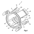
- FIG. 4 shows an isometric view of the locking element 1.
- the locking means 7 is in the form of the locking lug 8, which points radially inward, while the securing element 12 points radially outwards.
- the stop element 17, which is in the form of a rib, and the latching means 18 are provided, wherein the stop element 17 and locking means 18 point radially inward, while the securing element 21 extends radially outwards.
- the securing elements 12 and the securing elements 21 form an interrupted circular ring, ie have the same distance from the longitudinal axes 11, 32 or 33 (not shown here). That way - like out FIG. 3 can be seen - both the securing elements 12 and the securing elements 21 with the inclined surface 35 of the support member 22 cooperate to effect a limitation of the axial movement of the locking element 1 and an elastic deformation of the locking arms 2 radially inwardly.
- the FIG. 5 shows a plug-in coupling 37 for releasably connecting two lines 38 and 39.
- the first line 38 is assigned to a first coupling member 40 and the second line to a second coupling member 41.
- the support member 22 is fixed, wherein it is arranged in a housing 42 which has recesses 43 to allow actuation of the operating region 27 of the tongues 28.
- the recesses 43 are formed for this reason, also in the circumferential direction, only in the area of the operating areas 27.
- the locking element 1 is slidably disposed in the support member 22, wherein it is slidably mounted on the guide surface 30 of the sleeve 29.
- the sleeve 29 serves at the same time as a bearing surface 31 for the second coupling member 41.
- the sleeve 29 in this case comprises the second coupling member 41 in the circumferential direction completely. This is the case in particular in the region of an engagement element 29 'of the sleeve 29.
- This engagement element 29 ' engages in a radial gap between the coupling members 40 and 41 a. In this way, a radial guiding of the coupling members 40 and 41 and a radial displacement and / or tilting of the coupling members 40 and 41 is prevented, which increases both the stability and the tightness of the plug-in coupling 37.
- the second coupling member 41 has a retaining rib 44, which has a (advantageously flat) stop surface 45, which can cooperate with the (for example also flat) abutment surface 9 of the locking arm 2.
- the locking means 7 and the locking lug 8 engages over the retaining rib 44 in the radial direction such that the abutment surface 9 rests on the abutment surface 45.
- a possibly provided on the retaining rib 44 rounding or bevel is bridged so that the locking means 7 can not inadvertently slide off the retaining rib 44. Rather, there should always be a positive connection of latching means 7 and retaining rib 44 or the stop surfaces 9 and 45.
- the first coupling member 40 is designed in the embodiment shown here as an SAE housing.
- SAE housing a housing that corresponds to the first and / or the second coupling member 40 and / or 41 of the SAE standard.
- one or more seals for example in Shape of O-rings 51, arranged between the two O-rings 51 provided in this embodiment.
- a spacer 52 is arranged, which holds the two O-rings 51 in the axial direction at a defined minimum distance.
- the O-rings 51 are held by the engagement member 29 'at its axial position.
- the plug-in coupling 37 is provided to releasably connect the first line 38 to the second line 39.
- the second coupling member 41 as in the FIG. 5 shown, inserted into the first coupling member 40 until the locking lug 8 and the locking means 7, the retaining rib 44 engages behind and thus a latching holding the retaining rib 44 - which can also be referred to as a counter-locking element - realized.
- Holding stop surfaces 9 and 45 and 19 and 45 act together.
- FIG. 6 illustrates this connection operation of the coupling members 40 and 41 of the plug-in coupling 37.
- the second coupling member 41 is provided as a connection flange, for example on a housing, while the first coupling member 40, for example, a hose assembly is associated.
- the coupling members 40 and 41 are pushed onto each other or into each other.
- the second coupling member 41 is inserted into the first coupling member 40, which is illustrated by the arrow 53.
- the retaining rib 44 can be moved under the locking means 7 and the locking means 18 therethrough in the axial direction. Due to the interaction of the retaining rib 44 and the sliding surfaces 10 and 20, the locking element 1 is displaced into the position shown simultaneously or beforehand.
- the latching element 1 is supported in the radial direction by the guide surface 30 of the sleeve 29, while a recess 54 of the latching arm 2, which is provided in the radial direction below the actuating portion 6, cooperating with a portion of the first coupling member to another axial To shift the locking element 1 in the direction of the first coupling member 40 to prevent.
- the locking element 1 is in a Rastarmuzagabewolf. This means that the latching arm 2 or its latching means 7 can be readily displaced in the radial direction to the outside, as shown in the FIG. 6 is shown clearly. This applies analogously to the support arm. 3
- the securing element 12 enters into contact with the inclined surface 35 and, on the one hand, prevents further axial displacement of the latching element 1 and thus also of the second coupling element 41 and, on the other hand, causes a displacement of the latching means 7 in the radial direction inwards, so that this in the direction the retaining rib 44 is urged.
- the latching holding the retaining rib 44 by the locking means 7 and 18 thus represents a self-locking connection.
- the ring 25 of the base member 23 of the support member 22 thus prevents the second coupling member 41 can be pulled out of the first coupling member 40 and thus, that the lines 38 and 39 are separated from each other.
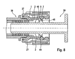
- FIG. 8 illustrates how the connection of the lines 38 and 39 can be solved.
- the locking element 1 must be moved to the Rastarmokgabegnasburg. This is done by the second coupling member 41 is displaced in the direction of the first coupling member 40.
- the holding rib 44 or its actuator surface 46 cooperates with the stop element 17 of the support arm 3 (not visible here), so that the latching element 1 is also moved in this direction.
- the latching element 1 is in its latching arm release position, the latching arms 2 can be displaced into a disconnected position by a simultaneous actuation of the two opposite operating areas 27. In this release position, the locking means 7 is brought into a position in which the stop surface 9 can no longer interact with the stop surface 45 of the retaining rib 44, so that it can be readily moved under the locking means 7.
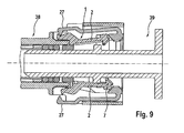
- FIG. 10 further clarifies the function of the stop element 17, which is provided on the support arms 3. It is shown that the actuator surface 46 of the retaining rib 44 cooperates with the stop member 17 to axially displace the detent member 1 toward the first coupling member 40 when the second coupling member 41 is displaced in that direction. It is also shown that the latching means 18 of the support arm 3 is slightly different from the latching means 7 of the latching arm 2. Here, too, lies the abutment surface 19, the sliding surface 20 and the securing element 21 before, however, the stop surface 19 is not provided here perpendicular to the longitudinal axis 33.
- the stop surface 19 may be an inclined surface, or, as in FIG. 10 shown, have a curvature or rounding, so that the retaining rib 44 for radially outward displacement of the locking means 18 can cooperate with this.
- the locking means 18 of the support arms 3 hold the retaining rib 44 only in the Rastarmtechnischswolf of the locking element 1.
- the carrier element 22 is simultaneously designed to hold the O-rings 51, that is to say the sealing elements, in position. For this purpose, it has the engagement element 29 '. Likewise, it serves as a guide element for the locking element 1 in the axial and radial directions and also as a stop for the locking element 1.
- the locking element 1 is guided on the guide surface 30 of the sleeve 29 of the support member 22.
- the carrier body 22 thus absorbs in the Rastarmuzagabe ein the radial forces which are caused for the radial displacement of the latching arms 2 in the disconnected position, without these forces on the first coupling member 40, which would lead to increased pull-out forces, that would make it difficult to take off the second coupling member 41 from the first coupling member 40.
- the locking element 1 can be made of a particularly flexurally elastic material, for example plastic.
- the locking element 1 structurally comparatively simple, since no stiffening ribs or the like must be provided in order to generate the forces necessary for the opening of the locking arms 2 and their displacement in the disconnected position.
Landscapes
- Engineering & Computer Science (AREA)
- General Engineering & Computer Science (AREA)
- Mechanical Engineering (AREA)
- Quick-Acting Or Multi-Walled Pipe Joints (AREA)
Applications Claiming Priority (2)
| Application Number | Priority Date | Filing Date | Title |
|---|---|---|---|
| DE102009033943A DE102009033943A1 (de) | 2009-07-14 | 2009-07-14 | Steckkupplung |
| PCT/EP2010/004027 WO2011006591A1 (de) | 2009-07-14 | 2010-07-03 | Steckkupplung |
Publications (2)
| Publication Number | Publication Date |
|---|---|
| EP2454514A1 EP2454514A1 (de) | 2012-05-23 |
| EP2454514B1 true EP2454514B1 (de) | 2013-09-11 |
Family
ID=42675187
Family Applications (1)
| Application Number | Title | Priority Date | Filing Date |
|---|---|---|---|
| EP10730375.2A Active EP2454514B1 (de) | 2009-07-14 | 2010-07-03 | Steckkupplung |
Country Status (5)
| Country | Link |
|---|---|
| US (1) | US9194521B2 (zh) |
| EP (1) | EP2454514B1 (zh) |
| CN (1) | CN102472424B (zh) |
| DE (1) | DE102009033943A1 (zh) |
| WO (1) | WO2011006591A1 (zh) |
Families Citing this family (33)
| Publication number | Priority date | Publication date | Assignee | Title |
|---|---|---|---|---|
| DE102011118099A1 (de) * | 2011-11-10 | 2013-05-16 | Illinois Tool Works Inc. | Vorrichtung zum Verbinden zweier Leitungsabschnitte |
| DE102012000607A1 (de) * | 2012-01-16 | 2013-07-18 | Norma Germany Gmbh | Kupplungselement und Entriegelungselement für das Kupplungselement |
| EP3332938B1 (en) * | 2012-07-02 | 2020-04-22 | Norma U.S. Holding LLC | Fuel line connector, method of making |
| DE102012106925A1 (de) * | 2012-07-30 | 2014-06-12 | Contitech Schlauch Gmbh | Schnellverbindungsanordnung zur lösbaren Verbindung einer Medienleitung mit einem Stutzen |
| DE102012107463A1 (de) * | 2012-08-15 | 2014-06-12 | Contitech Schlauch Gmbh | Schnellverbindungsanordnung zur lösbaren Verbindung einer Medienleitung mit einem Stutzen |
| EP3399220B1 (de) * | 2013-01-15 | 2019-05-15 | TI Automotive (Fuldabrück) GmbH | Schnellkupplung |
| US9523453B2 (en) * | 2013-03-20 | 2016-12-20 | Miniature Precision Components, Inc. | Locking quick connect assembly |
| FR3004506B1 (fr) * | 2013-04-15 | 2015-11-06 | Sartorius Stedim Biotech | Connexion fluidique securisee. |
| FR3021387B1 (fr) * | 2014-05-23 | 2016-07-01 | Staubli Sa Ets | Element male de raccord fluidique et raccord comprenant un tel element et un element femelle complementaire |
| DE112016003703T5 (de) * | 2015-08-14 | 2018-04-26 | Dana Canada Corporation | Rücklaufsperrventilanordnung mit einer integrierten Befestigungsfunktion |
| US10006577B2 (en) | 2016-07-15 | 2018-06-26 | Miniature Precision Components, Inc. | Permanent quick connector and assembly therewith |
| EP3379129B1 (de) * | 2017-03-23 | 2022-09-28 | Georg Fischer JRG AG | Anschlussverbinder |
| US11215306B2 (en) | 2017-04-19 | 2022-01-04 | Mueller International, Llc | Joint restraint device |
| US10677381B2 (en) | 2017-04-19 | 2020-06-09 | Mueller International, Llc | Joint restraint device |
| US11199280B2 (en) * | 2017-04-19 | 2021-12-14 | Mueller Intemational, LLC | Joint restraint device |
| US11131412B2 (en) * | 2017-04-19 | 2021-09-28 | Mueller International, Llc | Joint restraint device |
| DE102017208643B4 (de) * | 2017-05-22 | 2021-03-04 | Aft Automotive Gmbh | Kupplungselement zum Verbinden einer ersten fluidführenden Leitung mit einer zweiten fluidführenden Leitung sowie Kupplungsanordnung |
| EP3413405B1 (de) * | 2017-06-08 | 2019-03-13 | Rosenberger Hochfrequenztechnik GmbH & Co. KG | Verbinder |
| US10941887B2 (en) | 2017-07-13 | 2021-03-09 | Mueller International Llc | Wide range coupling |
| US10865922B2 (en) | 2017-10-05 | 2020-12-15 | Novares Us Engine Components, Inc. | Anti-tamper permanent quick connect coupling device |
| CN107816590A (zh) * | 2017-12-01 | 2018-03-20 | 重庆溯联汽车零部件有限公司 | 冷却管快速接头 |
| US11193609B2 (en) | 2018-02-28 | 2021-12-07 | Mueller International, Llc | Pipe coupling |
| US11867335B1 (en) * | 2018-06-13 | 2024-01-09 | Central Plastic Products LLC | Flexible tap tee fitting |
| US11473705B2 (en) | 2018-08-22 | 2022-10-18 | Mueller International, Llc | Joint restraint device |
| US10774508B2 (en) | 2018-09-04 | 2020-09-15 | Mueller International, Llc | Hydrant shoe assembly |
| US11162621B2 (en) | 2019-02-04 | 2021-11-02 | Mueller International, Llc | Gland assembly |
| DE102019107909A1 (de) * | 2019-03-27 | 2020-10-01 | Voss Fluid Gmbh | Steckverbindung für Fluid-Leitungen |
| US11396965B2 (en) | 2019-07-19 | 2022-07-26 | Mueller International, Llc | Restraint gripper cover with lockout breakaway |
| WO2021069048A1 (en) * | 2019-10-10 | 2021-04-15 | Oetiker Schweiz Ag | Quick connector made of plastics |
| DE102020104170A1 (de) * | 2020-02-18 | 2021-08-19 | Bayerische Motoren Werke Aktiengesellschaft | Anschlusseinrichtung für einen Getriebeentlüfter |
| CN113745900A (zh) * | 2021-08-19 | 2021-12-03 | 瑞肯耐特流体控制系统(镇江)有限公司 | 连接器 |
| US20230200348A1 (en) * | 2021-12-28 | 2023-06-29 | PetSmart Home Office, Inc. | Connecting rings for small animal habitat parts |
| DE102023108138B3 (de) | 2023-03-30 | 2024-05-16 | AUDI HUNGARIA Zrt. | Lösevorrichtung, Anordnung und Verfahren zum zerstörungsfreien Lösen einer Rastverbindung eines Bedienbauteils für ein Kraftfahrzeug |
Family Cites Families (12)
| Publication number | Priority date | Publication date | Assignee | Title |
|---|---|---|---|---|
| US1910706A (en) * | 1932-06-10 | 1933-05-23 | Hercules Coupling Company | Pipe or hose coupling |
| DE3705610A1 (de) * | 1987-02-21 | 1988-09-01 | Heinrich Vorschepoth | Loesbare steckverbindung fuer rohrleitungen |
| DE4020171C1 (zh) | 1990-06-25 | 1991-12-05 | Flexa Gmbh & Co Kg | |
| JPH0462012A (ja) | 1990-06-25 | 1992-02-27 | Toray Dow Corning Silicone Co Ltd | シリコーンゴム成形品の製造方法及び該成形品製造用の成形材料 |
| DE4107603C1 (zh) * | 1991-03-09 | 1992-02-06 | Rasmussen Gmbh, 6457 Maintal, De | |
| FR2715454B1 (fr) * | 1994-01-26 | 1996-04-12 | Caillau Ets | Connexion rapide. |
| DE19735491C1 (de) * | 1997-08-16 | 1998-07-16 | Rasmussen Gmbh | Steckkupplung zum Verbinden zweier Fluidleitungen |
| US6343630B1 (en) * | 1998-05-22 | 2002-02-05 | Delaware Capital Formation, Inc. | High pressure filling nozzle |
| DE19831897C2 (de) | 1998-07-16 | 2000-07-06 | Rasmussen Gmbh | Steckkupplung zum Verbinden zweier Fluidleitungen |
| EP1561990B1 (en) * | 2004-02-05 | 2008-08-20 | TI Group Automotive Systems LLC | Quick connector for high pressure applications |
| DE102004053541A1 (de) | 2004-11-05 | 2006-05-11 | Veritas Ag | Kupplungsvorrichtung zum Verbinden von Leitungen und Kraftfahrzeug mit einer derartigen Kupplungsvorrichtung |
| US7900972B2 (en) * | 2007-03-29 | 2011-03-08 | King Yuan Wang | Fluid connector for garden use |
-
2009
- 2009-07-14 DE DE102009033943A patent/DE102009033943A1/de not_active Withdrawn
-
2010
- 2010-07-03 WO PCT/EP2010/004027 patent/WO2011006591A1/de active Application Filing
- 2010-07-03 US US13/384,368 patent/US9194521B2/en active Active
- 2010-07-03 EP EP10730375.2A patent/EP2454514B1/de active Active
- 2010-07-03 CN CN201080032218.5A patent/CN102472424B/zh active Active
Also Published As
| Publication number | Publication date |
|---|---|
| US20120119485A1 (en) | 2012-05-17 |
| US9194521B2 (en) | 2015-11-24 |
| DE102009033943A1 (de) | 2011-01-20 |
| WO2011006591A1 (de) | 2011-01-20 |
| CN102472424A (zh) | 2012-05-23 |
| CN102472424B (zh) | 2014-02-26 |
| EP2454514A1 (de) | 2012-05-23 |
Similar Documents
| Publication | Publication Date | Title |
|---|---|---|
| EP2454514B1 (de) | Steckkupplung | |
| EP2880349B1 (de) | Schnellverbindungsanordnung zur lösbaren verbindung einer medienleitung mit einem stutzen | |
| EP1158236B1 (de) | Kupplungsvorrichtung mit einem U-förmigen Verriegelungselement | |
| DE102006062894B4 (de) | Schutzkappe | |
| EP3591277B1 (de) | Schnellkupplung | |
| EP1781979B1 (de) | Steckverbindung für fluid-leitungen | |
| EP2439439B1 (de) | Verbindungselement für eine Fluidverbindung | |
| WO1998028565A1 (de) | Zum anschluss eines schlauches mit einem zweiten bauteil vorgesehene schlauchkupplung | |
| EP2169293B1 (de) | Steckkupplung für Rohre, sowie Kupplungseinrichtung mit wenigstens zwei solchen Steckkupplungen | |
| EP3631275B1 (de) | Kupplungselement zum verbinden einer ersten fluidführenden leitung mit einer zweiten fluidführenden leitung sowie kupplungsanordnung | |
| EP2479470B1 (de) | Steckkupplung für Druckmittel-Leitungen | |
| EP1567800B1 (de) | Steckbarer und verrastbarer leitungsverbinder | |
| DE102009050076B3 (de) | Einsteckkupplung | |
| EP1731821A2 (de) | Schnellkupplung für ein Rohrsystem | |
| DE3705610A1 (de) | Loesbare steckverbindung fuer rohrleitungen | |
| EP2733403B1 (de) | Kupplungseinrichtung für Medienleitungen | |
| EP3361135B1 (de) | Schnellverbindungsvorrichtung und schnellverbindungssystem | |
| EP0691501B1 (de) | Steckverbinder für Schlauch- und/oder Rohrleitungen | |
| DE4328316C1 (de) | Steckkupplung | |
| EP1233227B9 (de) | Steckverbindung für Strömungsmittelleitungen | |
| DE10309725B3 (de) | Verfahren zum Herstellen einer Schnellkupplungsverbindung | |
| EP1790899B1 (de) | Steckkupplung zum Verbinden zweier Fluidleitungen | |
| EP0949442A2 (de) | Steckverbindung zweier Fluidleitungen |
Legal Events
| Date | Code | Title | Description |
|---|---|---|---|
| PUAI | Public reference made under article 153(3) epc to a published international application that has entered the european phase |
Free format text: ORIGINAL CODE: 0009012 |
|
| 17P | Request for examination filed |
Effective date: 20120214 |
|
| AK | Designated contracting states |
Kind code of ref document: A1 Designated state(s): AL AT BE BG CH CY CZ DE DK EE ES FI FR GB GR HR HU IE IS IT LI LT LU LV MC MK MT NL NO PL PT RO SE SI SK SM TR |
|
| RAP1 | Party data changed (applicant data changed or rights of an application transferred) |
Owner name: VOLKSWAGEN AKTIENGESELLSCHAFT Owner name: AFT AUTOMOTIVE GMBH&CO. KG |
|
| RIN1 | Information on inventor provided before grant (corrected) |
Inventor name: KRAMER, DIRK Inventor name: LAUMANN, ALFONS Inventor name: CELOVIC, SEVKET Inventor name: CICHOREK, HERMANN |
|
| DAX | Request for extension of the european patent (deleted) | ||
| GRAP | Despatch of communication of intention to grant a patent |
Free format text: ORIGINAL CODE: EPIDOSNIGR1 |
|
| GRAS | Grant fee paid |
Free format text: ORIGINAL CODE: EPIDOSNIGR3 |
|
| GRAA | (expected) grant |
Free format text: ORIGINAL CODE: 0009210 |
|
| AK | Designated contracting states |
Kind code of ref document: B1 Designated state(s): AL AT BE BG CH CY CZ DE DK EE ES FI FR GB GR HR HU IE IS IT LI LT LU LV MC MK MT NL NO PL PT RO SE SI SK SM TR |
|
| REG | Reference to a national code |
Ref country code: GB Ref legal event code: FG4D Free format text: NOT ENGLISH |
|
| REG | Reference to a national code |
Ref country code: CH Ref legal event code: EP |
|
| REG | Reference to a national code |
Ref country code: AT Ref legal event code: REF Ref document number: 631843 Country of ref document: AT Kind code of ref document: T Effective date: 20130915 |
|
| REG | Reference to a national code |
Ref country code: IE Ref legal event code: FG4D Free format text: LANGUAGE OF EP DOCUMENT: GERMAN |
|
| REG | Reference to a national code |
Ref country code: DE Ref legal event code: R096 Ref document number: 502010004704 Country of ref document: DE Effective date: 20131107 |
|
| RAP2 | Party data changed (patent owner data changed or rights of a patent transferred) |
Owner name: VOLKSWAGEN AKTIENGESELLSCHAFT Owner name: AFT AUTOMOTIVE GMBH & CO. KG |
|
| REG | Reference to a national code |
Ref country code: DE Ref legal event code: R081 Ref document number: 502010004704 Country of ref document: DE Owner name: VOLKSWAGEN AG, DE Free format text: FORMER OWNER: AFT AUTOMOTIVE GMBH & CO.KG, VOLKSWAGEN AG, , DE Effective date: 20131114 Ref country code: DE Ref legal event code: R081 Ref document number: 502010004704 Country of ref document: DE Owner name: AFT AUTOMOTIVE GMBH & CO. KG, DE Free format text: FORMER OWNER: AFT AUTOMOTIVE GMBH & CO.KG, VOLKSWAGEN AG, , DE Effective date: 20131114 Ref country code: DE Ref legal event code: R081 Ref document number: 502010004704 Country of ref document: DE Owner name: AFT AUTOMOTIVE GMBH & CO. KG, DE Free format text: FORMER OWNERS: AFT AUTOMOTIVE GMBH & CO.KG, 48356 NORDWALDE, DE; VOLKSWAGEN AG, 38440 WOLFSBURG, DE Effective date: 20131114 Ref country code: DE Ref legal event code: R081 Ref document number: 502010004704 Country of ref document: DE Owner name: VOLKSWAGEN AG, DE Free format text: FORMER OWNERS: AFT AUTOMOTIVE GMBH & CO.KG, 48356 NORDWALDE, DE; VOLKSWAGEN AG, 38440 WOLFSBURG, DE Effective date: 20131114 |
|
| PG25 | Lapsed in a contracting state [announced via postgrant information from national office to epo] |
Ref country code: SE Free format text: LAPSE BECAUSE OF FAILURE TO SUBMIT A TRANSLATION OF THE DESCRIPTION OR TO PAY THE FEE WITHIN THE PRESCRIBED TIME-LIMIT Effective date: 20130911 Ref country code: NO Free format text: LAPSE BECAUSE OF FAILURE TO SUBMIT A TRANSLATION OF THE DESCRIPTION OR TO PAY THE FEE WITHIN THE PRESCRIBED TIME-LIMIT Effective date: 20131211 Ref country code: LT Free format text: LAPSE BECAUSE OF FAILURE TO SUBMIT A TRANSLATION OF THE DESCRIPTION OR TO PAY THE FEE WITHIN THE PRESCRIBED TIME-LIMIT Effective date: 20130911 Ref country code: CY Free format text: LAPSE BECAUSE OF FAILURE TO SUBMIT A TRANSLATION OF THE DESCRIPTION OR TO PAY THE FEE WITHIN THE PRESCRIBED TIME-LIMIT Effective date: 20130828 Ref country code: HR Free format text: LAPSE BECAUSE OF FAILURE TO SUBMIT A TRANSLATION OF THE DESCRIPTION OR TO PAY THE FEE WITHIN THE PRESCRIBED TIME-LIMIT Effective date: 20130911 |
|
| REG | Reference to a national code |
Ref country code: NL Ref legal event code: VDEP Effective date: 20130911 |
|
| REG | Reference to a national code |
Ref country code: LT Ref legal event code: MG4D |
|
| PG25 | Lapsed in a contracting state [announced via postgrant information from national office to epo] |
Ref country code: SI Free format text: LAPSE BECAUSE OF FAILURE TO SUBMIT A TRANSLATION OF THE DESCRIPTION OR TO PAY THE FEE WITHIN THE PRESCRIBED TIME-LIMIT Effective date: 20130911 Ref country code: LV Free format text: LAPSE BECAUSE OF FAILURE TO SUBMIT A TRANSLATION OF THE DESCRIPTION OR TO PAY THE FEE WITHIN THE PRESCRIBED TIME-LIMIT Effective date: 20130911 Ref country code: GR Free format text: LAPSE BECAUSE OF FAILURE TO SUBMIT A TRANSLATION OF THE DESCRIPTION OR TO PAY THE FEE WITHIN THE PRESCRIBED TIME-LIMIT Effective date: 20131212 Ref country code: FI Free format text: LAPSE BECAUSE OF FAILURE TO SUBMIT A TRANSLATION OF THE DESCRIPTION OR TO PAY THE FEE WITHIN THE PRESCRIBED TIME-LIMIT Effective date: 20130911 |
|
| PG25 | Lapsed in a contracting state [announced via postgrant information from national office to epo] |
Ref country code: CY Free format text: LAPSE BECAUSE OF FAILURE TO SUBMIT A TRANSLATION OF THE DESCRIPTION OR TO PAY THE FEE WITHIN THE PRESCRIBED TIME-LIMIT Effective date: 20130911 |
|
| REG | Reference to a national code |
Ref country code: HU Ref legal event code: AG4A Ref document number: E019046 Country of ref document: HU |
|
| PG25 | Lapsed in a contracting state [announced via postgrant information from national office to epo] |
Ref country code: EE Free format text: LAPSE BECAUSE OF FAILURE TO SUBMIT A TRANSLATION OF THE DESCRIPTION OR TO PAY THE FEE WITHIN THE PRESCRIBED TIME-LIMIT Effective date: 20130911 Ref country code: RO Free format text: LAPSE BECAUSE OF FAILURE TO SUBMIT A TRANSLATION OF THE DESCRIPTION OR TO PAY THE FEE WITHIN THE PRESCRIBED TIME-LIMIT Effective date: 20130911 Ref country code: SK Free format text: LAPSE BECAUSE OF FAILURE TO SUBMIT A TRANSLATION OF THE DESCRIPTION OR TO PAY THE FEE WITHIN THE PRESCRIBED TIME-LIMIT Effective date: 20130911 Ref country code: IS Free format text: LAPSE BECAUSE OF FAILURE TO SUBMIT A TRANSLATION OF THE DESCRIPTION OR TO PAY THE FEE WITHIN THE PRESCRIBED TIME-LIMIT Effective date: 20140111 Ref country code: NL Free format text: LAPSE BECAUSE OF FAILURE TO SUBMIT A TRANSLATION OF THE DESCRIPTION OR TO PAY THE FEE WITHIN THE PRESCRIBED TIME-LIMIT Effective date: 20130911 Ref country code: CZ Free format text: LAPSE BECAUSE OF FAILURE TO SUBMIT A TRANSLATION OF THE DESCRIPTION OR TO PAY THE FEE WITHIN THE PRESCRIBED TIME-LIMIT Effective date: 20130911 |
|
| PG25 | Lapsed in a contracting state [announced via postgrant information from national office to epo] |
Ref country code: ES Free format text: LAPSE BECAUSE OF FAILURE TO SUBMIT A TRANSLATION OF THE DESCRIPTION OR TO PAY THE FEE WITHIN THE PRESCRIBED TIME-LIMIT Effective date: 20130911 Ref country code: PL Free format text: LAPSE BECAUSE OF FAILURE TO SUBMIT A TRANSLATION OF THE DESCRIPTION OR TO PAY THE FEE WITHIN THE PRESCRIBED TIME-LIMIT Effective date: 20130911 |
|
| REG | Reference to a national code |
Ref country code: DE Ref legal event code: R097 Ref document number: 502010004704 Country of ref document: DE |
|
| PG25 | Lapsed in a contracting state [announced via postgrant information from national office to epo] |
Ref country code: PT Free format text: LAPSE BECAUSE OF FAILURE TO SUBMIT A TRANSLATION OF THE DESCRIPTION OR TO PAY THE FEE WITHIN THE PRESCRIBED TIME-LIMIT Effective date: 20140113 |
|
| PLBE | No opposition filed within time limit |
Free format text: ORIGINAL CODE: 0009261 |
|
| STAA | Information on the status of an ep patent application or granted ep patent |
Free format text: STATUS: NO OPPOSITION FILED WITHIN TIME LIMIT |
|
| 26N | No opposition filed |
Effective date: 20140612 |
|
| PG25 | Lapsed in a contracting state [announced via postgrant information from national office to epo] |
Ref country code: IT Free format text: LAPSE BECAUSE OF FAILURE TO SUBMIT A TRANSLATION OF THE DESCRIPTION OR TO PAY THE FEE WITHIN THE PRESCRIBED TIME-LIMIT Effective date: 20130911 |
|
| REG | Reference to a national code |
Ref country code: DE Ref legal event code: R097 Ref document number: 502010004704 Country of ref document: DE Effective date: 20140612 |
|
| PG25 | Lapsed in a contracting state [announced via postgrant information from national office to epo] |
Ref country code: DK Free format text: LAPSE BECAUSE OF FAILURE TO SUBMIT A TRANSLATION OF THE DESCRIPTION OR TO PAY THE FEE WITHIN THE PRESCRIBED TIME-LIMIT Effective date: 20130911 |
|
| PG25 | Lapsed in a contracting state [announced via postgrant information from national office to epo] |
Ref country code: LU Free format text: LAPSE BECAUSE OF FAILURE TO SUBMIT A TRANSLATION OF THE DESCRIPTION OR TO PAY THE FEE WITHIN THE PRESCRIBED TIME-LIMIT Effective date: 20140703 |
|
| REG | Reference to a national code |
Ref country code: CH Ref legal event code: PL |
|
| REG | Reference to a national code |
Ref country code: IE Ref legal event code: MM4A |
|
| PG25 | Lapsed in a contracting state [announced via postgrant information from national office to epo] |
Ref country code: CH Free format text: LAPSE BECAUSE OF NON-PAYMENT OF DUE FEES Effective date: 20140731 Ref country code: LI Free format text: LAPSE BECAUSE OF NON-PAYMENT OF DUE FEES Effective date: 20140731 |
|
| PG25 | Lapsed in a contracting state [announced via postgrant information from national office to epo] |
Ref country code: IE Free format text: LAPSE BECAUSE OF NON-PAYMENT OF DUE FEES Effective date: 20140703 |
|
| PGFP | Annual fee paid to national office [announced via postgrant information from national office to epo] |
Ref country code: AT Payment date: 20150722 Year of fee payment: 6 |
|
| PG25 | Lapsed in a contracting state [announced via postgrant information from national office to epo] |
Ref country code: SM Free format text: LAPSE BECAUSE OF FAILURE TO SUBMIT A TRANSLATION OF THE DESCRIPTION OR TO PAY THE FEE WITHIN THE PRESCRIBED TIME-LIMIT Effective date: 20130911 Ref country code: MC Free format text: LAPSE BECAUSE OF FAILURE TO SUBMIT A TRANSLATION OF THE DESCRIPTION OR TO PAY THE FEE WITHIN THE PRESCRIBED TIME-LIMIT Effective date: 20130911 |
|
| PG25 | Lapsed in a contracting state [announced via postgrant information from national office to epo] |
Ref country code: BG Free format text: LAPSE BECAUSE OF FAILURE TO SUBMIT A TRANSLATION OF THE DESCRIPTION OR TO PAY THE FEE WITHIN THE PRESCRIBED TIME-LIMIT Effective date: 20130911 Ref country code: MT Free format text: LAPSE BECAUSE OF FAILURE TO SUBMIT A TRANSLATION OF THE DESCRIPTION OR TO PAY THE FEE WITHIN THE PRESCRIBED TIME-LIMIT Effective date: 20130911 |
|
| REG | Reference to a national code |
Ref country code: FR Ref legal event code: PLFP Year of fee payment: 7 |
|
| PG25 | Lapsed in a contracting state [announced via postgrant information from national office to epo] |
Ref country code: BE Free format text: LAPSE BECAUSE OF FAILURE TO SUBMIT A TRANSLATION OF THE DESCRIPTION OR TO PAY THE FEE WITHIN THE PRESCRIBED TIME-LIMIT Effective date: 20140731 |
|
| REG | Reference to a national code |
Ref country code: AT Ref legal event code: MM01 Ref document number: 631843 Country of ref document: AT Kind code of ref document: T Effective date: 20160703 |
|
| PG25 | Lapsed in a contracting state [announced via postgrant information from national office to epo] |
Ref country code: AT Free format text: LAPSE BECAUSE OF NON-PAYMENT OF DUE FEES Effective date: 20160703 |
|
| REG | Reference to a national code |
Ref country code: FR Ref legal event code: PLFP Year of fee payment: 8 |
|
| PGFP | Annual fee paid to national office [announced via postgrant information from national office to epo] |
Ref country code: TR Payment date: 20150703 Year of fee payment: 6 |
|
| PG25 | Lapsed in a contracting state [announced via postgrant information from national office to epo] |
Ref country code: MK Free format text: LAPSE BECAUSE OF FAILURE TO SUBMIT A TRANSLATION OF THE DESCRIPTION OR TO PAY THE FEE WITHIN THE PRESCRIBED TIME-LIMIT Effective date: 20130911 |
|
| REG | Reference to a national code |
Ref country code: FR Ref legal event code: PLFP Year of fee payment: 9 |
|
| PG25 | Lapsed in a contracting state [announced via postgrant information from national office to epo] |
Ref country code: AL Free format text: LAPSE BECAUSE OF FAILURE TO SUBMIT A TRANSLATION OF THE DESCRIPTION OR TO PAY THE FEE WITHIN THE PRESCRIBED TIME-LIMIT Effective date: 20130911 |
|
| PGFP | Annual fee paid to national office [announced via postgrant information from national office to epo] |
Ref country code: HU Payment date: 20180716 Year of fee payment: 9 |
|
| PG25 | Lapsed in a contracting state [announced via postgrant information from national office to epo] |
Ref country code: HU Free format text: LAPSE BECAUSE OF NON-PAYMENT OF DUE FEES Effective date: 20190704 |
|
| PG25 | Lapsed in a contracting state [announced via postgrant information from national office to epo] |
Ref country code: TR Free format text: LAPSE BECAUSE OF NON-PAYMENT OF DUE FEES Effective date: 20160703 |
|
| P01 | Opt-out of the competence of the unified patent court (upc) registered |
Effective date: 20230526 |
|
| PGFP | Annual fee paid to national office [announced via postgrant information from national office to epo] |
Ref country code: GB Payment date: 20230720 Year of fee payment: 14 |
|
| PGFP | Annual fee paid to national office [announced via postgrant information from national office to epo] |
Ref country code: FR Payment date: 20230725 Year of fee payment: 14 Ref country code: DE Payment date: 20230727 Year of fee payment: 14 |
|
| P02 | Opt-out of the competence of the unified patent court (upc) changed |
Effective date: 20231121 |