EP2454514B1 - Plug-in connector - Google Patents
Plug-in connector Download PDFInfo
- Publication number
- EP2454514B1 EP2454514B1 EP10730375.2A EP10730375A EP2454514B1 EP 2454514 B1 EP2454514 B1 EP 2454514B1 EP 10730375 A EP10730375 A EP 10730375A EP 2454514 B1 EP2454514 B1 EP 2454514B1
- Authority
- EP
- European Patent Office
- Prior art keywords
- latching
- coupling
- plug
- arm
- locking
- Prior art date
- Legal status (The legal status is an assumption and is not a legal conclusion. Google has not performed a legal analysis and makes no representation as to the accuracy of the status listed.)
- Active
Links
- 230000008878 coupling Effects 0.000 claims description 202
- 238000010168 coupling process Methods 0.000 claims description 202
- 238000005859 coupling reaction Methods 0.000 claims description 202
- 239000002184 metal Substances 0.000 claims description 3
- 230000013011 mating Effects 0.000 claims 4
- 238000002347 injection Methods 0.000 claims 1
- 239000007924 injection Substances 0.000 claims 1
- 238000006073 displacement reaction Methods 0.000 description 33
- 210000002105 tongue Anatomy 0.000 description 8
- 238000003825 pressing Methods 0.000 description 7
- 239000012530 fluid Substances 0.000 description 6
- 230000003993 interaction Effects 0.000 description 4
- 238000007789 sealing Methods 0.000 description 3
- 230000005489 elastic deformation Effects 0.000 description 2
- 210000005224 forefinger Anatomy 0.000 description 2
- 238000004519 manufacturing process Methods 0.000 description 2
- 239000000463 material Substances 0.000 description 2
- 230000002093 peripheral effect Effects 0.000 description 2
- 210000003813 thumb Anatomy 0.000 description 2
- 210000000078 claw Anatomy 0.000 description 1
- 230000001419 dependent effect Effects 0.000 description 1
- 230000000694 effects Effects 0.000 description 1
- 239000013013 elastic material Substances 0.000 description 1
- 238000005516 engineering process Methods 0.000 description 1
- 230000008014 freezing Effects 0.000 description 1
- 238000007710 freezing Methods 0.000 description 1
- 238000001746 injection moulding Methods 0.000 description 1
- 238000009434 installation Methods 0.000 description 1
- 238000000034 method Methods 0.000 description 1
- 230000000284 resting effect Effects 0.000 description 1
- 125000006850 spacer group Chemical group 0.000 description 1
- 238000009827 uniform distribution Methods 0.000 description 1
Images


Classifications
-
- F—MECHANICAL ENGINEERING; LIGHTING; HEATING; WEAPONS; BLASTING
- F16—ENGINEERING ELEMENTS AND UNITS; GENERAL MEASURES FOR PRODUCING AND MAINTAINING EFFECTIVE FUNCTIONING OF MACHINES OR INSTALLATIONS; THERMAL INSULATION IN GENERAL
- F16L—PIPES; JOINTS OR FITTINGS FOR PIPES; SUPPORTS FOR PIPES, CABLES OR PROTECTIVE TUBING; MEANS FOR THERMAL INSULATION IN GENERAL
- F16L37/00—Couplings of the quick-acting type
- F16L37/08—Couplings of the quick-acting type in which the connection between abutting or axially overlapping ends is maintained by locking members
- F16L37/084—Couplings of the quick-acting type in which the connection between abutting or axially overlapping ends is maintained by locking members combined with automatic locking
- F16L37/098—Couplings of the quick-acting type in which the connection between abutting or axially overlapping ends is maintained by locking members combined with automatic locking by means of flexible hooks
- F16L37/0985—Couplings of the quick-acting type in which the connection between abutting or axially overlapping ends is maintained by locking members combined with automatic locking by means of flexible hooks the flexible hook extending radially inwardly from an outer part and engaging a bead, recess or the like on an inner part
-
- F—MECHANICAL ENGINEERING; LIGHTING; HEATING; WEAPONS; BLASTING
- F16—ENGINEERING ELEMENTS AND UNITS; GENERAL MEASURES FOR PRODUCING AND MAINTAINING EFFECTIVE FUNCTIONING OF MACHINES OR INSTALLATIONS; THERMAL INSULATION IN GENERAL
- F16L—PIPES; JOINTS OR FITTINGS FOR PIPES; SUPPORTS FOR PIPES, CABLES OR PROTECTIVE TUBING; MEANS FOR THERMAL INSULATION IN GENERAL
- F16L37/00—Couplings of the quick-acting type
- F16L37/08—Couplings of the quick-acting type in which the connection between abutting or axially overlapping ends is maintained by locking members
- F16L37/084—Couplings of the quick-acting type in which the connection between abutting or axially overlapping ends is maintained by locking members combined with automatic locking
- F16L37/098—Couplings of the quick-acting type in which the connection between abutting or axially overlapping ends is maintained by locking members combined with automatic locking by means of flexible hooks
- F16L37/0982—Couplings of the quick-acting type in which the connection between abutting or axially overlapping ends is maintained by locking members combined with automatic locking by means of flexible hooks with a separate member for releasing the coupling
Definitions
- the invention relates to a plug-in coupling for releasably connecting two lines, with a first coupling member, a second coupling member, a fastened to the first coupling member support member and at least one latching arm, arranged on the carrier element latching element, wherein the latching arm in a detent position for latching holding the a latching counter element having the second coupling member is formed and the latching element is arranged to be slidable in the
- Plug-in couplings of the type mentioned are known from the prior art.
- this describes EP 0 465 896 B1 a connecting element for corrugated pipes and hoses with parallel corrugated hose wall, wherein the connecting element comprises an approximately cylindrical housing with a connector and in the housing wall a plurality of window-like openings and an attachable to the housing support ring with a frontal annular surface and with legs and locking parts at the free ends.
- the support ring in the form of a sliding sleeve of a stop ring, an axially spaced inner ring, the stop ring and the inner ring connecting webs and extending from the inner ring to the stop ring down legs with the locking claws at the free ends.
- two opposing locking elements are provided, which surround a locking counter-element - a circumferential rib - a nozzle and keep it in place.
- the latching arms are provided on an annular latching element and connected to each other via this.
- said sliding sleeve must be displaced axially, so that the locking element or the latching arms attached thereto reach a Rastarmuzagabewolf.
- the two coupling members can be separated from one another by vigorous pulling in the axial direction, wherein the latching arms are pressed outward in the radial direction by this pulling, so that they are present in a disconnected position.
- the latching arms can each comprise only a small angular range (in the circumferential direction) of the latching counter element. This reduces the reliability of the plug-in coupling especially with an application of lateral load, as may occur, for example, in an accident of a motor vehicle.
- the second coupling member which is held by means of the latching arms, even under tensile load (ie during operation) by axially displacing the sliding sleeve are released from the first coupling member. This represents a further source of danger in the event of an accident since under certain circumstances an unintentional release of the connection can occur.
- FIG. 1 Another, similar plug-in coupling shows the DE 198 31 897 C2 ,
- a plug-in coupling for connecting two fluid lines is presented, wherein the one fluid line has a holding rib.
- the plug-in coupling has a sleeve and an axially displaceably guided in the sleeve latching device on a ring axially extending and resiliently flexible retaining arms with a hook formed on the free end for engaging behind the retaining rib having.
- a decoupling of the two fluid lines is provided by the support arms are brought into an axially retracted unlocking position of the latching device in which the hooks are not pressed with a radially outer inclined surface against a front edge of a breakthrough and can be spread radially outward.
- a force in the radial direction is applied inwardly to at least one of the latching arms, whereby the latching element is displaced in the axial direction to the rear.
- the locking element is displaced into the Rastarmuzagabegna.
- the application of force can be done for example by pressing with the thumb and forefinger of one hand.
- the latching arms can be spread by pulling apart the lines or the coupling members axially so that thereafter by further axial pulling apart of the lines they can be separated from each other. For displacing the latching element into the latching arm release position, it is sufficient to actuate one of the latching arms.
- Plug-in couplings of this type are usually mounted and released by hand, with certain assembly or disassembly forces must not be exceeded.
- the latching arms must hold the latching counter element as possible in such a way that they be moved in an axial displacement of the second coupling member relative to the first coupling member (away from this) in the locking position or pushed into it.
- the plug-in coupling must be easy to solve in case of disassembly. This forces in the interpretation of the locking arms to compromise. In particular, the biasing forces of the locking arms must not be too high.
- the locking lugs provided on the latching arms may not completely enclose the latching counter element of the second coupling member for this purpose. Rather, it must be ensured by curves or oblique surfaces on an inner side of the latching lugs or the latching arms that when opening the plug-in coupling by the axial pulling apart of the coupling members or the lines, the latching arms can be displaced radially outwardly without much resistance.
- even small external influences which may be caused for example by jamming or freezing, are sufficient to allow the latching element to remain in its latching arm release position. This can lead to unintentional release of the plug-in coupling by pulling on one of the coupling members. In particular, even with the occurrence of strong vibrations or in an accident, there may be an unintentional displacement of the locking element and thus to a release of the connection.
- the carrier element can be fastened, on which the latching element is arranged.
- the latching element has the at least one latching arm, which cooperates with a latching counter element (for example, a retaining rib) of the second coupling member to hold this detent when the latching arm is in the latching position. If the connection is to be released, then the locking element is to be displaced in the
- the locking arms are secured so that they do not release the locking counter-element of the second coupling member and thus this can not be separated from the first coupling member.
- the latching arms are in contrast in the radial direction by actuation of the control element elastically deflectable, so that the second coupling member can be separated by axial displacement of the first coupling member.
- the latching arm can be brought into the disconnected position only in the Rastarmokgabe ein the locking element by actuation of the at least one operating element.
- the operating element can for example be assigned to the carrier element or attached thereto.
- the control element can also be brought into connection for releasing the connection with the plug-in coupling. For this purpose, it is introduced for example by a recess in the carrier element for displacing the latching arm.
- the connection of the two lines or the coupling members can not be solved by accidentally pressing the control element in such a plug-in coupling, whereby a very secure and reliable connection of the two lines is achieved.
- connection made by the plug-in coupling of the two lines is self-locking, a mere displacement of the coupling members in the axial direction to each other - without the Rastarmuzagabegna and operating the control element - thus only leads to that the locking arm is urged in the direction of the locking counter-element, so that the connection the more secure it is.
- a development of the invention provides that the Rastarmokgabegnagnagnan an engagement position in which the operating element cooperates with the at least one latching arm, and the Rastarm refreshmentssggi is a non-engagement position.
- the operating element is assigned to the carrier element.
- the disengaged position so that the control can not interact with the locking arms.
- engagement elements of the operating element can interact with counter-engagement elements of the latching arm.
- the latching element has at least one stop element which cooperates with the latching counter element for displacing the latching element in Rastarmgolgabewolf. It is thus not only intended that the latching arm cooperates with the locking counter-element, but it is also the stop element before.
- the stop element can engage, for example, on the side facing away from the locking arm of the locking counter-element on this.
- a development of the invention provides that the stop element is provided on a support arm and / or the support arm.
- the support arm is assigned to the locking element or attached to this.
- the locking element thus has both the locking arm and the support arm. If a plurality of latching arms or support arms are provided, then the latching arms and support arms can be provided alternately. Preferably, two locking arms and two support arms are each provided diametrically opposite each other.
- the stop element can be arranged both on the support arm and on the latching arm or in each case on both.
- the support arm has latching means to cooperate, at least in the Rastarmtechnischswolf with the locking counter-element for engaging behind the second coupling member.
- the latching means is provided on the support arm.
- the latching means is, in contrast to the latching arm, but only intended to engage behind the locking counter-element, so as to hold the second coupling member, while the latching element is in the Rastarmtechnischswolf.
- the latching element is in the latching arm release position, then it can be provided that the latching engagement (or latching) can be achieved by displacing the coupling members axially relative to one another.
- the locking means may be configured such that they are deflected resiliently in the axial displacement in the radial direction outwards, so that the locking counter-element can be moved away under them.
- the latching element if the latching element is in the latching arm securing position, then the latching means having support arms as well as the latching arms are provided to ensure reliable holding of the second coupling member or of the latching counter-element.
- the support arm, as well as the latching arm at an axial displacement of the coupling members apart, when the locking element in the Rastarm Kliswolf and not in the Rastarmgolgabewolf ein, urged in the direction of the locking counter-element, that the connection of the lines or the coupling members is ensured.
- the locking means may for example be provided with a sliding surface, which ensures the radial displacement of the support arm.
- the sliding surface may be an inclined surface and / or bent.
- the carrier element has at least one holding means to hold the latching arm and / or the latching means of the support arm in the presence of Rastarmtechnischswolf the locking element in the locked position.
- the holding means is used in particular to the locking arm and / or the support arm or its locking means in an axial displacement of the coupling members apart, while the locking element is in the Rastarmtechnischswolf to hold the locking arm or the support arm in the locked position or to urge into it and thus the latching holding or to ensure the latching interaction with the locking counter-element.
- a rear grip connection - that is, a positive connection - before.
- a development of the invention provides that a plurality of latching arms are provided, each latching arm is associated with an operating element and only when actuated at least two of the operating elements, the latching elements can be brought into the disconnected position.
- the latching arms are preferably distributed over a circumference of the latching element.
- the provided for example on the support element controls are assigned to the latching arms so that each control can act exclusively on a latching arm, especially when the latching element is in the Rastarmuzagabewolfwolfwolfwolf. Only the locking arms, but not the support arms associated with the controls.
- at least two of the controls preferably all controls must be operated to bring the locking arms in the disconnected position. So it is only then a release of the connection possible if both the locking element has been moved to the Rastarmokgabegnagna, and at least two controls are actuated.
- a very reliable and secured against incorrect operation or unintentional release system is created.
- a development of the invention provides that the latching arms are arranged diametrically opposite one another. Such an arrangement is particularly advantageous when each locking arm is associated with a control element, since in this case the then also oppositely arranged operating elements can be actuated, for example, with thumb and forefinger each with opposing force. At the same time results from the diametrical arrangement of the locking arms uniform introduction of the holding force of the locking arms and / or support arms on the locking counter-element of the second coupling member.
- the latching element is socket-shaped and / or the at least one latching arm and the at least one support arm are arranged distributed over the circumference of the latching element.
- Socket-shaped means that the second coupling member and / or a portion of the support member is received in the locking element, in particular the locking element is precisely matched to this or this.
- the latching element can thus essentially have a circular cross section and also serve - together with the carrier element - as a guide element for the second coupling member and / or the carrier element.
- the locking arm and the support arm are provided on the latching element in a preferred embodiment, wherein these are distributed over the circumference of the latching element. For example, it can be provided a uniform distribution and locking arm and support arm can be arranged alternately.
- the operating element is a flexible tongue.
- the flexible tongue is on it as well bush-shaped support member attached or formed together with this.
- the control element need not have an additional joint, since it has sufficient flexibility of itself to be actuated to release the connection and to cooperate with the latching arm.
- the flexible tongue is in the form of a rocker, so preferably has a free end.
- a further development of the invention provides that the latching arm and the latching counter element have cooperating stop surfaces which are substantially perpendicular to a longitudinal axis of the first and / or the second coupling member.
- the stop surfaces are provided. With these locking arm and locking counter-element contact each other to prevent release of the first coupling member of the two coupling member when the locking arms are not present in the disconnected position.
- the vertical arrangement to the longitudinal axis of the coupling members prevents sliding of the abutment surfaces on each other when an axial force acts on the coupling members to divide them apart.
- the vertically arranged stop surface allows a simple release of the connection, should this be intended.
- the carrier element has a guide surface for the latching element, which lies at least partially between the second coupling member and the latching element.
- the guide surface may be part of the sleeve-shaped carrier element or a sleeve-shaped region of the carrier element which guides both the detent element and the second coupling member.
- the latching element rests on the guide surface of the carrier element, wherein the contact between latching element and guide surface is formed such that a tilting of the latching element with respect to the carrier element is largely prevented.
- the locking element is thus on with a certain axial extent on the guide surface.
- the guide surface is provided between the second coupling member and the latching element. This means that the carrier element comes into contact with the side facing away from the guide surface with the second coupling member and this also leads or supports, ie stabilized in the radial direction.
- a further development of the invention provides that a bearing point for the latching element is present on the carrier element, in particular on its guide surface.
- the bearing is, for example, a fulcrum, so a support point around which a rotational movement can take place.
- the latching element rests on the carrier element or the guide surface in such a way that the rotational movement is permitted - at least of regions, in particular of the latching arm and / or the support arm - of the latching element.
- This is intended primarily to enable a rotational movement of the latching arm or of the support arm.
- the rotational movement is described by the latching arm or support arm during a displacement into the disconnected position, that is then, when the control is operated.
- the latching element is supported on the bearing point in such a way that the forces caused by the displacement in the radial direction are absorbed by the carrier element. This means that they will not be impressed on the second coupling member, which would make it difficult to move the coupling members apart when the connection is released. The release of the connection is thus supported by the support member by radial forces acting on the locking element or portions thereof, are absorbed by the support member and not transmitted to one of the coupling members.
- the carrier element has an engagement element which is arranged radially between the first coupling member and the second coupling member.
- the engagement element is at least bereivati on its circumference to the first and / or second coupling member.
- a further development of the invention provides that the engagement element is designed to hold at least one seal axially.
- the engagement element engages in a gap, which is present in the radial direction between the coupling members.
- a seal is also arranged to produce a tight connection by means of the plug-in coupling can.
- the engaging element is suitably arranged to prevent the seal from moving out of this gap.
- the seal is fixed by means of the engagement element in the axial direction.
- a further development of the invention provides a deformable base element of the latching element for substantially independent axial displacement of a plurality of latching arms.
- the locking element is axially displaced as a unit to bring it in Rastarm remediess- or Rastarmgolgabegna.
- the plug-in coupling is designed such that only one actuation of a plurality of operating elements, which are each assigned to a latching arm, leads to displacing the latching arms into the disconnected position, the latching arms should be able to be displaced essentially independently of one another. In this way it is achieved that a portion of the locking element may be present in the Rastarmgolgabegna, while the other is in the Rastarm remediesswolf.
- the operating element is integrally formed with the carrier element and / or the latching arm with the latching element. So there is no multi-part design, in particular, the control element or the locking arm is not subsequently attached to the support member or the locking element.
- a uniform material design of the operating element with the carrier element or the latching arm with the latching element are present, but it may also be advantageous to have a multi-component design.
- the support element itself can be made of a comparatively rigid material, while the control element is flexible or elastic.
- a development of the invention provides that the latching element and / or the carrier element consists of a plastic. Manufacturing plastic is easy, fast and inexpensive possible. At the same time, a plastic can be selected, which meets the strength requirements of the plug-in coupling.
- a development of the invention provides that the latching element and / or the carrier element is a molded part.
- the elements can be manufactured by means of an injection molding process. This also makes it possible to carry out a quick, simple and cost-effective production.
- a development of the invention provides that the carrier element and / or latching element at least partially in a housing, in particular made of plastic or metal, are arranged.
- the above described plug-in coupling allows a universal installation of carrier element and locking element in the housing.
- the housing may for example consist of plastic or be made of metal.
- An attachment of carrier element and locking element on the housing may be provided, for example, by latching or other suitable connection technology.
- a development of the invention provides that the carrier element and / or the housing has a recess for the operating element.
- the operating element can be arranged by or in the recess so that it can cooperate in the engaged position with the latching arm to bring it into the release position.
- the control element must therefore not be fixedly attached to the support member or the housing (which may be the case), but rather only then fed through the recess when a displacement of the latching arm in the disconnected position - after moving the locking element in the Rastarmokgabewolf ein - should be done.
- FIG. 1 shows a locking element 1 in a sectional view, which in the illustrated example via two diametrically opposed locking arms 2 and two also diametrically opposite each other arranged support arms 3 has.
- the latching arms 2 and the support arms 3 are arranged on an annular base element 4. It is provided that both the latching arms 2 and the support arms 3 in the radial direction are at least partially flexible, but at least with respect to the base member 4 are elastically deflectable in the radial direction.
- the latching arm 2 has a latching region 5 and an actuating region 6.
- the latching area 5 is on the one hand (in FIG. 1 right) of the base member 4, the actuating portion 6 arranged on the other one.
- the latching region 5 can be deflected in the opposite direction due to the flexible attachment to the base element 4.
- the latching arm 2 in its latching region 5 has a latching means 7, which is designed as a latching lug 8.
- the locking lug 8 has on its one side a stop surface 9 and on its other side a sliding surface 10.
- the stop surface 9 is provided, for example, substantially perpendicular to a longitudinal axis 11 of the latching element 1 and shows, starting from the latching arm 2, radially inwardly. Alternatively, however, the stop surface 9 may also be inclined with its radially inward-pointing end in the direction of the actuating region 6.
- the sliding surface 10 is arranged obliquely with respect to the longitudinal axis 11.
- a securing element 12 is formed on the latching arm 2.
- the fuse element 12 is a substantially rectangular projection which faces radially outward.
- the bearing point 13 The area in which the latching arm 2 is fastened to the base element 4 is referred to hereinafter as the bearing point 13, also if only in a figurative sense.
- the locking arm 2 can be angled with respect to the base member 4, for example, when in the operating region 6, the radially inwardly directed force is applied.
- the latching arm 2 itself must be designed such that it is stiff enough to implement a displacement of the actuating region 6 radially inwardly into a radially outwardly pointing displacement of the latching region 5.
- the base member 4 is elastically deformed in the region of the bearing 13.
- stiffening means may be provided.
- the latching arm 2 has an engagement counter-element 14 and a support region 15. Both the engagement counter-element 14 and the support region 15 are increased in the radial direction relative to the intermediate region outwardly, so that a later-described engagement element 16 can engage in this area.
- the stop element 17 is substantially rectangular in its cross section and has, starting from the support arm 3, radially inwards. In this case, an inwardly and in the direction of the locking means 7 facing edge have a chamfer, so be bevelled.
- the latching means 18, however, is similar to the latching means 7, thus has radially inward and next to a stop surface 19 has a facing away from this sliding surface 20 and a radially outwardly facing securing element 21 (not here visible).
- the stop surface 19 of the support arm 3 is inclined and has, with its radially inwardly directed end not in the direction of the actuating portion 6, but in the opposite direction.
- the abutment surface 19 need not be a plane, but may for example have a curvature or a radius in its cross section.
- the latching element 1 is formed substantially bush-shaped, wherein the latching arms 2 and the support arms 3 are arranged distributed radially over the circumference of the latching element 1 and in each case diametrically opposite each other.
- the FIG. 2 shows a carrier element 22 in a sectional view.
- controls 24 are arranged elastically deflectable. Overall, two controls 24 are provided, which are diametrically opposed to each other.
- the controls 24 are attached to a ring 25 of the base member 23 so that they are elastically deformable in a bearing 26 and thus by a radially inwardly directed force on an operating area 27 together with the engaging member 16 which is provided on the control element 24 radially can be relocated inside.
- the operating element 24 is formed in this embodiment as a flexible tongue 28 or flexible rocker.
- the base element 23 of the carrier element 22 also has a sleeve 29, which forms a guide surface 30 on its outer peripheral surface.
- the sleeve 29 has with its radially inner circumferential surface over a bearing surface 31.
- the sleeve 29 and the ring 25 are preferably held by the base member 23 relative to each other positionally fixed, this area of the support member 22 is thus preferably designed to be rigid.
- the carrier element 22 is formed substantially symmetrically to its longitudinal axis 32.
- the sleeve 29 forms with its guide surface 30 at the same time a pivot point for the locking element 1 and its base element 4, when the inward-facing force for displacing the latching area 5 is applied to the actuating portion 6.
- FIG. 3 shows a common sectional view of the locking element 1 and the support member 22, wherein the locking element 1 is supported in the support member 22.
- the latching element 1 and the carrier element 22 have a common longitudinal axis 33, in which the longitudinal axis 11 and the longitudinal axis 32 extend coaxially.
- the latching element 1 is arranged in the carrier element 22 such that it is supported by a running surface 34 - which may be formed by the latching arms 2 and / or the support arms 3 - of the guide surface 30 of the sleeve 29.
- the latching element 1 is arranged displaceably in this way in the support member 22, so in the axial direction - that is, in the direction of the longitudinal axis 33 - to be moved.
- Moving out of the locking element 1 from the carrier element 22 is not possible.
- a movement of the locking element 1 out of the carrier element 22 to the right is prevented by an interaction of the securing element 12 and an inclined surface 35, which is provided on the ring 25 of the support member 22.
- the inclined surface 35 is formed such that it comes to a right movement in a further movement of the locking element 1 to a radial displacement of the latching portion 5 and the locking means 7 of the latching arm 2.
- the latching arm 2 is elastically deformed.
- a move out the latching element 1 from the carrier element 22 to the left is prevented by an interaction of the stop surface 9 with a counter-surface 36, which is represented by an end face of the ring 25.
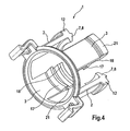
- FIG. 4 shows an isometric view of the locking element 1.
- the locking means 7 is in the form of the locking lug 8, which points radially inward, while the securing element 12 points radially outwards.
- the stop element 17, which is in the form of a rib, and the latching means 18 are provided, wherein the stop element 17 and locking means 18 point radially inward, while the securing element 21 extends radially outwards.
- the securing elements 12 and the securing elements 21 form an interrupted circular ring, ie have the same distance from the longitudinal axes 11, 32 or 33 (not shown here). That way - like out FIG. 3 can be seen - both the securing elements 12 and the securing elements 21 with the inclined surface 35 of the support member 22 cooperate to effect a limitation of the axial movement of the locking element 1 and an elastic deformation of the locking arms 2 radially inwardly.
- the FIG. 5 shows a plug-in coupling 37 for releasably connecting two lines 38 and 39.
- the first line 38 is assigned to a first coupling member 40 and the second line to a second coupling member 41.
- the support member 22 is fixed, wherein it is arranged in a housing 42 which has recesses 43 to allow actuation of the operating region 27 of the tongues 28.
- the recesses 43 are formed for this reason, also in the circumferential direction, only in the area of the operating areas 27.
- the locking element 1 is slidably disposed in the support member 22, wherein it is slidably mounted on the guide surface 30 of the sleeve 29.
- the sleeve 29 serves at the same time as a bearing surface 31 for the second coupling member 41.
- the sleeve 29 in this case comprises the second coupling member 41 in the circumferential direction completely. This is the case in particular in the region of an engagement element 29 'of the sleeve 29.
- This engagement element 29 ' engages in a radial gap between the coupling members 40 and 41 a. In this way, a radial guiding of the coupling members 40 and 41 and a radial displacement and / or tilting of the coupling members 40 and 41 is prevented, which increases both the stability and the tightness of the plug-in coupling 37.
- the second coupling member 41 has a retaining rib 44, which has a (advantageously flat) stop surface 45, which can cooperate with the (for example also flat) abutment surface 9 of the locking arm 2.
- the locking means 7 and the locking lug 8 engages over the retaining rib 44 in the radial direction such that the abutment surface 9 rests on the abutment surface 45.
- a possibly provided on the retaining rib 44 rounding or bevel is bridged so that the locking means 7 can not inadvertently slide off the retaining rib 44. Rather, there should always be a positive connection of latching means 7 and retaining rib 44 or the stop surfaces 9 and 45.
- the first coupling member 40 is designed in the embodiment shown here as an SAE housing.
- SAE housing a housing that corresponds to the first and / or the second coupling member 40 and / or 41 of the SAE standard.
- one or more seals for example in Shape of O-rings 51, arranged between the two O-rings 51 provided in this embodiment.
- a spacer 52 is arranged, which holds the two O-rings 51 in the axial direction at a defined minimum distance.
- the O-rings 51 are held by the engagement member 29 'at its axial position.
- the plug-in coupling 37 is provided to releasably connect the first line 38 to the second line 39.
- the second coupling member 41 as in the FIG. 5 shown, inserted into the first coupling member 40 until the locking lug 8 and the locking means 7, the retaining rib 44 engages behind and thus a latching holding the retaining rib 44 - which can also be referred to as a counter-locking element - realized.
- Holding stop surfaces 9 and 45 and 19 and 45 act together.
- FIG. 6 illustrates this connection operation of the coupling members 40 and 41 of the plug-in coupling 37.
- the second coupling member 41 is provided as a connection flange, for example on a housing, while the first coupling member 40, for example, a hose assembly is associated.
- the coupling members 40 and 41 are pushed onto each other or into each other.
- the second coupling member 41 is inserted into the first coupling member 40, which is illustrated by the arrow 53.
- the retaining rib 44 can be moved under the locking means 7 and the locking means 18 therethrough in the axial direction. Due to the interaction of the retaining rib 44 and the sliding surfaces 10 and 20, the locking element 1 is displaced into the position shown simultaneously or beforehand.
- the latching element 1 is supported in the radial direction by the guide surface 30 of the sleeve 29, while a recess 54 of the latching arm 2, which is provided in the radial direction below the actuating portion 6, cooperating with a portion of the first coupling member to another axial To shift the locking element 1 in the direction of the first coupling member 40 to prevent.
- the locking element 1 is in a Rastarmuzagabewolf. This means that the latching arm 2 or its latching means 7 can be readily displaced in the radial direction to the outside, as shown in the FIG. 6 is shown clearly. This applies analogously to the support arm. 3
- the securing element 12 enters into contact with the inclined surface 35 and, on the one hand, prevents further axial displacement of the latching element 1 and thus also of the second coupling element 41 and, on the other hand, causes a displacement of the latching means 7 in the radial direction inwards, so that this in the direction the retaining rib 44 is urged.
- the latching holding the retaining rib 44 by the locking means 7 and 18 thus represents a self-locking connection.
- the ring 25 of the base member 23 of the support member 22 thus prevents the second coupling member 41 can be pulled out of the first coupling member 40 and thus, that the lines 38 and 39 are separated from each other.
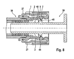
- FIG. 8 illustrates how the connection of the lines 38 and 39 can be solved.
- the locking element 1 must be moved to the Rastarmokgabegnasburg. This is done by the second coupling member 41 is displaced in the direction of the first coupling member 40.
- the holding rib 44 or its actuator surface 46 cooperates with the stop element 17 of the support arm 3 (not visible here), so that the latching element 1 is also moved in this direction.
- the latching element 1 is in its latching arm release position, the latching arms 2 can be displaced into a disconnected position by a simultaneous actuation of the two opposite operating areas 27. In this release position, the locking means 7 is brought into a position in which the stop surface 9 can no longer interact with the stop surface 45 of the retaining rib 44, so that it can be readily moved under the locking means 7.
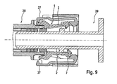
- FIG. 10 further clarifies the function of the stop element 17, which is provided on the support arms 3. It is shown that the actuator surface 46 of the retaining rib 44 cooperates with the stop member 17 to axially displace the detent member 1 toward the first coupling member 40 when the second coupling member 41 is displaced in that direction. It is also shown that the latching means 18 of the support arm 3 is slightly different from the latching means 7 of the latching arm 2. Here, too, lies the abutment surface 19, the sliding surface 20 and the securing element 21 before, however, the stop surface 19 is not provided here perpendicular to the longitudinal axis 33.
- the stop surface 19 may be an inclined surface, or, as in FIG. 10 shown, have a curvature or rounding, so that the retaining rib 44 for radially outward displacement of the locking means 18 can cooperate with this.
- the locking means 18 of the support arms 3 hold the retaining rib 44 only in the Rastarmtechnischswolf of the locking element 1.
- the carrier element 22 is simultaneously designed to hold the O-rings 51, that is to say the sealing elements, in position. For this purpose, it has the engagement element 29 '. Likewise, it serves as a guide element for the locking element 1 in the axial and radial directions and also as a stop for the locking element 1.
- the locking element 1 is guided on the guide surface 30 of the sleeve 29 of the support member 22.
- the carrier body 22 thus absorbs in the Rastarmuzagabe ein the radial forces which are caused for the radial displacement of the latching arms 2 in the disconnected position, without these forces on the first coupling member 40, which would lead to increased pull-out forces, that would make it difficult to take off the second coupling member 41 from the first coupling member 40.
- the locking element 1 can be made of a particularly flexurally elastic material, for example plastic.
- the locking element 1 structurally comparatively simple, since no stiffening ribs or the like must be provided in order to generate the forces necessary for the opening of the locking arms 2 and their displacement in the disconnected position.
Description
Die Erfindung betrifft eine Steckkupplung zum lösbaren Verbinden zweier Leitungen, mit einem ersten Kupplungsglied, einem zweiten Kupplungsglied, einem an dem ersten Kupplungsglied befestigbaren Trägerelement und einem mindestens einen Rastarm aufweisenden, an dem Trägerelement angeordneten Rastelement, wobei der Rastarm in einer Raststellung zum rastenden Halten des ein Rastgegenelement aufweisenden zweiten Kupplungsglieds ausgebildet ist und das Rastelement in axialer Richtung zum Einnehmen zumindest einer Rastarmsicherungs- und einer Rastarmfreigabestellung zu dem Trägerelement verschieblich angeordnet ist.The invention relates to a plug-in coupling for releasably connecting two lines, with a first coupling member, a second coupling member, a fastened to the first coupling member support member and at least one latching arm, arranged on the carrier element latching element, wherein the latching arm in a detent position for latching holding the a latching counter element having the second coupling member is formed and the latching element is arranged to be slidable in the axial direction for taking at least one Rastarmsicherungs- and a Rastarmfreigabestellung to the support element.
Steckkupplungen der eingangs genannten Art sind aus dem Stand der Technik bekannt. Beispielsweise beschreibt die
Eine weitere, ähnliche Steckkupplung zeigt die
Zum Lösen der Steckkupplung wird eine Kraft in radialer Richtung nach innen auf zumindest einen der Rastarme aufgebracht, wodurch das Rastelement in axialer Richtung nach hinten verlagert wird. Dadurch wird das Rastelement in die Rastarmfreigabestellung verlagert. Das Aufbringen der Kraft kann beispielsweise durch Drücken mittels Daumen und Zeigefinger einer Hand erfolgen. In der Rastarmfreigabestellung, auch als Entriegelungslage bezeichnet, können die Rastarme durch axiales Auseinanderziehen der Leitungen beziehungsweise der Kupplungsglieder derart gespreizt werden, dass danach durch weiteres axiales Auseinanderziehen der Leitungen diese voneinander getrennt werden können. Zum Verlagern des Rastelements in die Rastarmfreigabestellung genügt es, einen der Rastarme zu betätigen.To release the plug-in coupling, a force in the radial direction is applied inwardly to at least one of the latching arms, whereby the latching element is displaced in the axial direction to the rear. As a result, the locking element is displaced into the Rastarmfreigabestellung. The application of force can be done for example by pressing with the thumb and forefinger of one hand. In the Rastarmfreigabestellung, also referred to as Entriegelungslage, the latching arms can be spread by pulling apart the lines or the coupling members axially so that thereafter by further axial pulling apart of the lines they can be separated from each other. For displacing the latching element into the latching arm release position, it is sufficient to actuate one of the latching arms.
Steckkupplungen dieser Art werden in der Regel von Hand montiert und gelöst, wobei bestimmte Montage- beziehungsweise Demontagekräfte nicht überschritten werden dürfen. Einerseits müssen die Rastarme das Rastgegenelement möglichst derart halten, dass sie bei einer axialen Verlagerung des zweiten Kupplungsglieds relativ zum ersten Kupplungsglied (von diesem weg) in die Raststellung bewegt beziehungsweise in diese hineingedrängt werden. Andererseits muss sich die Steckkupplung im Demontagefall leicht lösen lassen. Dies zwingt bei der Auslegung der Rastarme zu Kompromissen. Insbesondere dürfen die Vorspannkräfte der Rastarme nicht zu hoch sein.Plug-in couplings of this type are usually mounted and released by hand, with certain assembly or disassembly forces must not be exceeded. On the one hand, the latching arms must hold the latching counter element as possible in such a way that they be moved in an axial displacement of the second coupling member relative to the first coupling member (away from this) in the locking position or pushed into it. On the other hand, the plug-in coupling must be easy to solve in case of disassembly. This forces in the interpretation of the locking arms to compromise. In particular, the biasing forces of the locking arms must not be too high.
Die an den Rastarmen vorgesehenen Rastnasen dürfen dazu das Rastgegenelement des zweiten Kupplungsglieds nicht vollständig umschließen. Vielmehr muss durch Rundungen oder Schrägflächen an einer Innenseite der Rastnasen beziehungsweise der Rastarme sichergestellt sein, dass bei einem Öffnen der Steckkupplung durch das axiale Auseinanderziehen der Kupplungsglieder beziehungsweise der Leitungen die Rastarme ohne großen Widerstand radial nach außen verlagert werden können. Allerdings reichen bereits kleine äußere Einflüsse, die beispielsweise durch Verklemmen oder Festfrieren verursacht sein können, aus, um das Rastelement in seiner Rastarmfreigabestellung verharren zu lassen. Dies kann zu einem unbeabsichtigten Lösen der Steckkupplung durch Ziehen an einem der Kupplungsglieder führen. Insbesondere auch bei Auftreten von starken Vibrationen beziehungsweise bei einem Unfall kann es zu einem unbeabsichtigten Verlagern des Rastelements und damit zu einem Lösen der Verbindung kommen.The locking lugs provided on the latching arms may not completely enclose the latching counter element of the second coupling member for this purpose. Rather, it must be ensured by curves or oblique surfaces on an inner side of the latching lugs or the latching arms that when opening the plug-in coupling by the axial pulling apart of the coupling members or the lines, the latching arms can be displaced radially outwardly without much resistance. However, even small external influences, which may be caused for example by jamming or freezing, are sufficient to allow the latching element to remain in its latching arm release position. This can lead to unintentional release of the plug-in coupling by pulling on one of the coupling members. In particular, even with the occurrence of strong vibrations or in an accident, there may be an unintentional displacement of the locking element and thus to a release of the connection.
Bedingt durch die relativ geringe Haltekraft, die notwendig ist, um das Rastelement in der Rastarmfreigabestellung zu halten, ist es auch nicht möglich, ohne großen konstruktiven Aufwand eine Steckkupplung zu realisieren, welche nur durch Betätigen von mindestens zwei Rastarmen geöffnet werden kann. Selbst wenn die aus dem Stand der Technik bekannten Steckkupplungen mit mehreren, insbesondere zwei gegenüberliegenden Rastarmen beziehungsweise Bedienelementen versehen sind, reicht üblicherweise die Betätigung eines Rastarms beziehungsweise Bedienelement aus, um das Rastelement in die Rastarmfreigabestellung zu verschieben und damit ein Lösen der Verbindung, welche mittels der Steckkupplung hergestellt ist, zu ermöglichen. Dies ist beispielsweise bei einem Unfall kritisch zu sehen, da dabei die Steckkupplung gegen ein benachbartes Bauteil gedrückt werden kann, wodurch es zu einem Betätigen des Rastarms beziehungsweise des Bedienelements und damit zu einem Lösen der Verbindung kommen kann.Due to the relatively low holding force, which is necessary to hold the locking element in the Rastarmfreigabestellung, it is also not possible to realize a plug-in coupling without great design effort, which can only be opened by pressing at least two locking arms. Even if those from the Prior art known plug-in couplings are provided with several, in particular two opposing locking arms or controls, usually sufficient to actuate a latching arm or control element to move the locking element in the Rastarmfreigabestellung and thus releasing the connection, which is made by means of the plug-in to enable. This can be seen critically in an accident, for example, because the plug-in coupling can be pressed against an adjacent component, which can lead to an actuation of the latching arm or the operating element and thus to a release of the connection.
Bei der Steckkupplung, wie sie in der
Weitere Steckkupplungen mit den Merkmalen gemäß des Oberbegriffs von Anspruch 1 sind bekannt aus
Es ist daher Aufgabe der Erfindung, eine Steckkupplung zum lösbaren Verbinden zweier Leitungen vorzuschlagen, welche die eingangs genannten Nachteile nicht aufweist, sondern insbesondere ein Lösen der Verbindung lediglich zulässt, wenn das Rastelement zuvor bewusst in die Rastarmfreigabestellung bewegt wurde.It is therefore an object of the invention to provide a plug-in coupling for releasably connecting two lines, which does not have the disadvantages mentioned, but in particular release of the connection only allows if the locking element was previously deliberately moved into the Rastarmfreigabestellung.
Dies wird erfindungsgemäß mit einer Steckkupplung mit den in Anspruch 1 genannten Merkmalen erreicht. Dabei ist vorgesehen, dass, insbesondere an dem Trägerelement, ein in der Rastarmfreigabestellung zur Verlagerung des Rastarms in eine Trennstellung betätigbares Bedienelement vorgesehen ist, welches bei Betätigung in der Rastarmsicherungsstellung das Rastelement in der Rastarmsicherungsstellung hält. Mittels der beschriebenen Steckkupplung können zwei Leitungen lösbar verbunden werden. Dazu weist die Steckkupplung das erste Kupplungsglied und das zweite Kupplungsglied auf - die zum Beispiel jeweils nach der SAE-Norm (SAE: Society of Automotive Engineers) ausgebildet sind -, die jeweils einer der beiden Leitungen zugeordnet sind. An dem ersten Kupplungsglied ist das Trägerelement befestigbar, an welchem das Rastelement angeordnet ist. Das Rastelement weist den mindestens einen Rastarm auf, der mit einem Rastgegenelement (beispielsweise einer Halterippe) des zweiten Kupplungsglieds zusammenwirkt, um dieses rastend zu halten, wenn sich der Rastarm in der Raststellung befindet. Soll die Verbindung gelöst werden, so ist das Rastelement in axialer Richtung zu verlagern, wobei es die Rastarmsicherungsstellung und die Rastarmfreigabestellung einnehmen kann. Das Verlagern erfolgt relativ zu dem Trägerelement.This is achieved according to the invention with a plug-in coupling with the features mentioned in
In der Rastarmsicherungsstellung sind die Rastarme derart gesichert, dass sie das Rastgegenelement des zweiten Kupplungsglieds nicht freigeben und dies somit nicht von dem ersten Kupplungsglied getrennt werden kann. In der Rastarmfreigabestellung sind die Rastarme hingegen insbesondere in radialer Richtung durch Betätigung des Bedienelements elastisch auslenkbar, sodass das zweite Kupplungsglied durch axiales Verlagern von dem ersten Kupplungsglied getrennt werden kann. Durch das Betätigen des Bedienelements wird der Rastarm in die Trennstellung verlagert, in welcher das zweite Kupplungsglied von dem ersten Kupplungsglied getrennt werden kann. Es muss also zunächst das Rastelement axial verschoben werden, sodass es in die Rastarmfreigabestellung gelangt. Anschließend muss das Bedienelement betätigt werden, um den Rastarm in die Trennstellung zu bringen. Nur bei Vorliegen des Rastelements in der Rastarmfreigabestellung kann der Rastarm durch Betätigung des Bedienelements in die Trennstellung gelangen, welche zum Lösen der Verbindung notwendig ist. Somit ist kein unbeabsichtigtes Lösen der Verbindung möglich, sondern es ist stets ein aktives Eingreifen des Nutzers notwendig, der bewusst die beiden zum Lösen der Verbindung notwendigen Schritte durchführen muss. Bei einer Betätigung des Bedienelements in der Rastarmsicherungsstellung verleibt das Rastelement in der Rastarmsicherungsstellung oder wird sogar in dieser gehalten oder in diese gedrängt.In the Rastarmsicherungsstellung the locking arms are secured so that they do not release the locking counter-element of the second coupling member and thus this can not be separated from the first coupling member. In the Rastarmfreigabestellung, however, the latching arms are in contrast in the radial direction by actuation of the control element elastically deflectable, so that the second coupling member can be separated by axial displacement of the first coupling member. By pressing the operating element of the locking arm is displaced into the release position, in which the second coupling member are separated from the first coupling member can. So it must first be moved axially the locking element so that it enters the Rastarmfreigabestellung. Subsequently, the operating element must be actuated to bring the locking arm in the disconnected position. Only in the presence of the locking element in the Rastarmfreigabestellung the locking arm can reach by operating the control element in the disconnected position, which is necessary to release the connection. Thus, no unintentional release of the connection is possible, but it is always an active intervention of the user necessary, which must consciously perform the two necessary to release the connection steps. Upon actuation of the operating element in the Rastarmsicherungsstellung the locking element in the Rastarmsicherungsstellung or is even held in this or pushed into it.
Zusätzlich ist vorgesehen, dass bei Betätigung des Bedienelements das Rastelement in der Rastarmsicherungsstellung gehalten ist beziehungsweise in diese gedrängt wird, wenn das Bedienelement betätigt wird, während sich das Rastelement in der Rastarmsicherungsstellung befindet. Es sind also stets zwei Schritte zum Lösen der Verbindung beziehungsweise der Steckkupplung notwendig. Das axiale Verschieben des Rastelements kann dabei beispielsweise derart erfolgen, dass das zweite Kupplungsglied mit dem Rastelement zusammenwirkt, um es bei einem axialen Verlagern des zweiten Kupplungsglieds in Richtung des ersten Kupplungsglieds in Richtung der Rastarmfreigabestellung zu verlagern. Lediglich ein Betätigen des Bedienelements kann das Rastelement nicht in die Rastarmfreigabestellung bringen und somit nicht zu einem Lösen der Verbindung führen.In addition, it is provided that upon actuation of the operating element, the latching element is held in the Rastarmsicherungsstellung or is urged into this, when the operating element is actuated, while the latching element is in the Rastarmsicherungsstellung. So there are always two steps to release the connection or the plug-in coupling necessary. The axial displacement of the latching element can for example be such that the second coupling member cooperates with the latching element to displace it in the direction of the first coupling member in the direction of Rastarmfreigabestellung upon axial displacement of the second coupling member. Only an actuation of the operating element can not bring the locking element into the Rastarmfreigabestellung and thus do not lead to a release of the connection.
Es ist also eine Steckkupplung realisiert, bei welcher der Rastarm nur in der Rastarmfreigabestellung des Rastelements durch Betätigung des mindestens einen Bedienelements in die Trennstellung bringbar ist. Das Bedienelement kann beispielsweise dem Trägerelement zugeordnet beziehungsweise an diesem befestigt sein. Das Bedienelement kann auch erst zum Lösen der Verbindung mit der Steckkupplung in Verbindung gebracht werden. Dazu wird es beispielsweise durch eine Ausnehmung in dem Trägerelement zur Verlagerung des Rastarms eingebracht. Die Verbindung der beiden Leitungen beziehungsweise der Kupplungsglieder kann bei einer solchen Steckkupplung nicht durch versehentliches Betätigen des Bedienelements gelöst werden, wodurch eine sehr sichere und zuverlässige Verbindung der beiden Leitungen erreicht ist. Dabei ist die mittels der Steckkupplung hergestellte Verbindung der beiden Leitungen selbsthemmend, ein bloßes Verlagern der Kupplungsglieder in axialer Richtung zueinander - ohne Vorliegen der Rastarmfreigabestellung und Betätigen des Bedienelements - führt also lediglich dazu, dass der Rastarm in Richtung des Rastgegenelements gedrängt wird, sodass die Verbindung umso sicherer gehalten wird.It is thus realized a plug-in coupling, wherein the latching arm can be brought into the disconnected position only in the Rastarmfreigabestellung the locking element by actuation of the at least one operating element. The operating element can for example be assigned to the carrier element or attached thereto. The control element can also be brought into connection for releasing the connection with the plug-in coupling. For this purpose, it is introduced for example by a recess in the carrier element for displacing the latching arm. The connection of the two lines or the coupling members can not be solved by accidentally pressing the control element in such a plug-in coupling, whereby a very secure and reliable connection of the two lines is achieved. In this case, the connection made by the plug-in coupling of the two lines is self-locking, a mere displacement of the coupling members in the axial direction to each other - without the Rastarmfreigabestellung and operating the control element - thus only leads to that the locking arm is urged in the direction of the locking counter-element, so that the connection the more secure it is.
Weitere vorteilhafte Ausgestaltungen ergeben sich aus den Unteransprüchen.Further advantageous embodiments will be apparent from the dependent claims.
Eine Weiterbildung der Erfindung sieht vor, dass die Rastarmfreigabestellung eine Eingriffsstellung, in welcher das Bedienelement mit dem mindestens einen Rastarm zusammenwirkt, und die Rastarmsicherungsstellung eine Nichteingriffsstellung ist. Dabei ist das Bedienelement dem Trägerelement zugeordnet. Durch das axiale Verschieben des Rastelements bezüglich des Trägerelements wird erreicht, dass in der Rastarmsicherungsstellung das Bedienelement mit dem Rastarm zusammenwirken kann, um diesen in die Trennstellung zu verlagern. Dahingegen ist dies in der Rastarmsicherungsstellung gerade nicht vorgesehen. Hier liegt also die Nichteingriffsstellung vor, sodass das Bedienelement nicht mit den Rastarmen zusammenwirken kann. In der Eingriffsstellung können beispielsweise Eingriffselemente des Bedienelements mit Eingriffsgegenelementen des Rastarms zusammenwirken.A development of the invention provides that the Rastarmfreigabestellung an engagement position in which the operating element cooperates with the at least one latching arm, and the Rastarmsicherungsstellung is a non-engagement position. In this case, the operating element is assigned to the carrier element. By the axial displacement of the locking element relative to the carrier element is achieved that in the Rastarmsicherungsstellung the operating element can interact with the latching arm to move it to the release position. In contrast, this is just not provided in the Rastarmsicherungsstellung. So here is the disengaged position, so that the control can not interact with the locking arms. In the engaged position, for example, engagement elements of the operating element can interact with counter-engagement elements of the latching arm.
Eine Weiterbildung der Erfindung sieht vor, dass das Rastelement mindestens ein Anschlagelement aufweist, welches mit dem Rastgegenelement zum Verlagern des Rastelements in Rastarmfreigabestellung zusammenwirkt. Es ist somit nicht nur vorgesehen, dass der Rastarm mit dem Rastgegenelement zusammenwirkt, sondern es liegt zusätzlich das Anschlagelement vor. Dabei kann das Anschlagelement beispielsweise auf der dem Rastarm abgewandten Seite des Rastgegenelements an diesem angreifen. Mittels des Anschlagelements kann erreicht werden, dass das Rastelement bei einem Verlagern des zweiten Kupplungsglieds in Richtung des ersten Kupplungsglieds das Rastelement in Richtung der Rastarmfreigabestellung bewegt beziehungsweise tatsächlich in diese verlagert wird. Somit ist ein Lösen der Verbindung der beiden Leitungen einfach möglich, indem die beiden Kupplungsglieder in axialer Richtung aufeinander zu verlagert werden und bei Erreichen der Rastarmfreigabestellung durch das Rastelement das Bedienelement betätigt wird. Anschließend können die Kupplungsglieder in axialer Richtung auseinandergezogen werden, womit die Verbindung gelöst ist.A further development of the invention provides that the latching element has at least one stop element which cooperates with the latching counter element for displacing the latching element in Rastarmfreigabestellung. It is thus not only intended that the latching arm cooperates with the locking counter-element, but it is also the stop element before. In this case, the stop element can engage, for example, on the side facing away from the locking arm of the locking counter-element on this. By means of the stop element can be achieved that the locking element is moved in a displacement of the second coupling member in the direction of the first coupling member, the locking element in the direction of Rastarmfreigabestellung or actually shifted in this. Thus, a release of the connection of the two lines is easily possible by the two coupling members are displaced toward each other in the axial direction and upon reaching the Rastarmfreigabestellung by the locking element, the operating element is actuated. Subsequently, the coupling members can be pulled apart in the axial direction, whereby the connection is released.
Eine Weiterbildung der Erfindung sieht vor, dass das Anschlagelement an einem Stützarm und/oder dem Stützarm vorgesehen ist. Der Stützarm ist dabei dem Rastelement zugeordnet beziehungsweise an diesem befestigt. Das Rastelement weist somit sowohl den Rastarm als auch den Stützarm auf. Sind mehrere Rastarme beziehungsweise Stützarme vorgesehen, so können die Rastarme und Stützarme alternierend vorgesehen sein. Vorzugsweise sind jeweils zwei Rastarme und zwei Stützarme jeweils diametral zueinander vorgesehen. Das Anschlagelement kann sowohl an dem Stützarm als auch an dem Rastarm oder jeweils an beiden angeordnet sein.A development of the invention provides that the stop element is provided on a support arm and / or the support arm. The support arm is assigned to the locking element or attached to this. The locking element thus has both the locking arm and the support arm. If a plurality of latching arms or support arms are provided, then the latching arms and support arms can be provided alternately. Preferably, two locking arms and two support arms are each provided diametrically opposite each other. The stop element can be arranged both on the support arm and on the latching arm or in each case on both.
Eine Weiterbildung der Erfindung sieht vor, dass der Stützarm Rastmittel aufweist, um zumindest in der Rastarmsicherungsstellung mit dem Rastgegenelement zum hintergreifenden Halten des zweiten Kupplungsglieds zusammenzuwirken. Neben dem Anschlagelement ist also an dem Stützarm das Rastmittel vorgesehen. Das Rastmittel ist, im Gegensatz zu dem Rastarm, jedoch lediglich dazu vorgesehen, das Rastgegenelement zu hintergreifen, um so das zweite Kupplungsglied zu halten, während sich das Rastelement in der Rastarmsicherungsstellung befindet. Liegt das Rastelement dagegen in der Rastarmfreigabestellung vor, so kann es vorgesehen sein, dass das hintergreifende (oder ebenfalls rastende) Halten durch axiales Verlagern der Kupplungsglieder zueinander gelöst werden kann. Dazu können die Rastmittel derart ausgestaltet sein, dass sie bei dem axialen Verlagern in radialer Richtung nach außen federnd ausgelenkt werden, sodass das Rastgegenelement unter ihnen hinwegverlagert werden kann. Liegt das Rastelement dagegen in der Rastarmsicherungsstellung vor, so sind die Rastmittel aufweisenden Stützarme ebenso wie die Rastarme dazu vorgesehen, ein zuverlässiges Halten des zweiten Kupplungsglieds beziehungsweise des Rastgegenelements sicherzustellen. Dabei wird der Stützarm, ebenso wie der Rastarm, bei einem axialen Verlagern der Kupplungsglieder auseinander, wenn sich das Rastelement in der Rastarmsicherungsstellung und nicht in der Rastarmfreigabestellung befindet, derart in Richtung des Rastgegenelements gedrängt, dass die Verbindung der Leitungen beziehungsweise der Kupplungsglieder sichergestellt ist. Zu diesem Zweck kann das Rastmittel beispielsweise mit einer Gleitfläche versehen sein, welche das radiale Verlagern des Stützarms sicherstellt. Die Gleitfläche kann eine Schrägfläche sein und/oder gebogen verlaufen. Durch das gleichzeitige Vorsehen von Rastarm und Stützarm kann die Abstützung des zweiten Kupplungsglieds in Bezug auf das erste Kupplungsglied deutlich verbessert werden. Insbesondere wird auf diese Weise eine Mehrpunktabstützung bei Zugbelastung der Verbindung in axialer Richtung erreicht. Mit Vorteil werden zwei Rastarme und zwei Stützarme an dem Rastelement angeordnet, sodass eine Vierpunktabstützung erreicht wird.A further development of the invention provides that the support arm has latching means to cooperate, at least in the Rastarmsicherungsstellung with the locking counter-element for engaging behind the second coupling member. In addition to the stop element so the latching means is provided on the support arm. The latching means is, in contrast to the latching arm, but only intended to engage behind the locking counter-element, so as to hold the second coupling member, while the latching element is in the Rastarmsicherungsstellung. On the other hand, if the latching element is in the latching arm release position, then it can be provided that the latching engagement (or latching) can be achieved by displacing the coupling members axially relative to one another. For this purpose, the locking means may be configured such that they are deflected resiliently in the axial displacement in the radial direction outwards, so that the locking counter-element can be moved away under them. On the other hand, if the latching element is in the latching arm securing position, then the latching means having support arms as well as the latching arms are provided to ensure reliable holding of the second coupling member or of the latching counter-element. In this case, the support arm, as well as the latching arm, at an axial displacement of the coupling members apart, when the locking element in the Rastarmsicherungsstellung and not in the Rastarmfreigabestellung, urged in the direction of the locking counter-element, that the connection of the lines or the coupling members is ensured. For this purpose, the locking means may for example be provided with a sliding surface, which ensures the radial displacement of the support arm. The sliding surface may be an inclined surface and / or bent. By the simultaneous provision of locking arm and support arm, the support of the second coupling member with respect to the first coupling member can be significantly improved. In particular, in this way a multi-point support is achieved with tensile load of the connection in the axial direction. Advantageously, two locking arms and two support arms are arranged on the locking element, so that a four-point support is achieved.
Eine Weiterbildung der Erfindung sieht vor, dass das Trägerelement mindestens ein Haltemittel aufweist, um den Rastarm und/oder die Rastmittel des Stützarms bei Vorliegen der Rastarmsicherungsstellung des Rastelements in der Raststellung zu halten. Das Haltemittel dient insbesondere dazu, den Rastarm und/oder den Stützarm beziehungsweise dessen Rastmittel bei einem axialen Verlagern der Kupplungsglieder auseinander, während das Rastelement in der Rastarmsicherungsstellung vorliegt, den Rastarm beziehungsweise den Stützarm in der Raststellung zu halten beziehungsweise in diese zu drängen und damit das rastende Halten beziehungsweise das rastende Zusammenwirken mit dem Rastgegenelement sicherzustellen. Beispielsweise liegt in der Raststellung zwischen Rastarm und/oder den Rastmitteln und dem Rastgegenelement eine Hintergriffsverbindung - also eine Formschlussverbindung - vor. Mittels der Haltemittel wird verhindert, dass Rastarm beziehungsweise Rastmittel aus dieser heraus in die Trennstellung gelangen können.A development of the invention provides that the carrier element has at least one holding means to hold the latching arm and / or the latching means of the support arm in the presence of Rastarmsicherungsstellung the locking element in the locked position. The holding means is used in particular to the locking arm and / or the support arm or its locking means in an axial displacement of the coupling members apart, while the locking element is in the Rastarmsicherungsstellung to hold the locking arm or the support arm in the locked position or to urge into it and thus the latching holding or to ensure the latching interaction with the locking counter-element. For example, in the locking position between the latching arm and / or the latching means and the latching counter element, a rear grip connection - that is, a positive connection - before. By means of the holding means prevents latching arm or locking means can get out of this out into the release position.
Es handelt sich also bei der lösbaren Verbindung um eine selbsthemmende Verbindung, welche vorzugsweise derart ausgestaltet ist, dass bei einem axialen Verlagern der Kupplungsglieder voneinander weg - ohne vorheriges Verlagern des Rastelements in die Rastarmfreigabestellung und Betätigen des Bedienelements - der Rastarm und/oder die Rastmittel des Stützarms in die Raststellung gedrängt werden.So it is at the releasable connection to a self-locking connection, which is preferably designed such that in an axial displacement of the coupling members away from each other - without prior displacement of the locking element in the Rastarmfreigabestellung and operating the operating element - the locking arm and / or the locking means of Support arm are urged into the locked position.
Eine Weiterbildung der Erfindung sieht vor, dass mehrere Rastarme vorgesehen sind, jedem Rastarm ein Bedienelement zugeordnet ist und ausschließlich bei Betätigung mindestens zwei der Bedienelemente die Rastelemente in die Trennstellung bringbar sind. Die Rastarme sind dabei vorzugsweise über einen Umfang des Rastelements verteilt angeordnet. Die beispielsweise an dem Trägerelement vorgesehenen Bedienelemente sind derart den Rastarmen zugeordnet, dass jedes Bedienelement exklusiv auf einen Rastarm wirken kann, insbesondere wenn sich das Rastelement in der Rastarmfreigabestellung befindet. Dabei sind lediglich den Rastarmen, nicht jedoch den Stützarmen die Bedienelemente zugeordnet. Um die Verbindung der beiden Leitungen beziehungsweise Kupplungsglieder zu lösen, ist es nun vorgesehen, dass mindestens zwei der Bedienelemente, vorzugsweise alle Bedienelemente, betätigt werden müssen, um die Rastarme in die Trennstellung zu bringen. Es ist also lediglich dann ein Lösen der Verbindung möglich, wenn sowohl das Rastelement in die Rastarmfreigabestellung verlagert wurde als auch mindestens zwei Bedienelemente betätigt werden. Somit ist ein sehr zuverlässiges und gegen Fehlbedienungen beziehungsweise unbeabsichtigtes Lösen gesichertes System geschaffen.A development of the invention provides that a plurality of latching arms are provided, each latching arm is associated with an operating element and only when actuated at least two of the operating elements, the latching elements can be brought into the disconnected position. The latching arms are preferably distributed over a circumference of the latching element. The provided for example on the support element controls are assigned to the latching arms so that each control can act exclusively on a latching arm, especially when the latching element is in the Rastarmfreigabestellung. Only the locking arms, but not the support arms associated with the controls. In order to solve the connection of the two lines or coupling members, it is now provided that at least two of the controls, preferably all controls must be operated to bring the locking arms in the disconnected position. So it is only then a release of the connection possible if both the locking element has been moved to the Rastarmfreigabestellung and at least two controls are actuated. Thus, a very reliable and secured against incorrect operation or unintentional release system is created.
Eine Weiterbildung der Erfindung sieht vor, dass die Rastarme einander diametral gegenüberliegend angeordnet sind. Eine solche Anordnung ist insbesondere dann vorteilhaft, wenn jedem Rastarm ein Bedienelement zugeordnet ist, da in diesem Fall die dann ebenfalls gegenüberliegend angeordneten Bedienelemente beispielsweise mit Daumen und Zeigefinger mit jeweils entgegengerichteter Krafteinwirkung betätigt werden können. Gleichzeitig ergibt sich durch die diametrale Anordnung der Rastarme eine gleichmäßige Einleitung der Haltekraft der Rastarme und/oder Stützarme auf das Rastgegenelement des zweiten Kupplungsglieds.A development of the invention provides that the latching arms are arranged diametrically opposite one another. Such an arrangement is particularly advantageous when each locking arm is associated with a control element, since in this case the then also oppositely arranged operating elements can be actuated, for example, with thumb and forefinger each with opposing force. At the same time results from the diametrical arrangement of the locking arms uniform introduction of the holding force of the locking arms and / or support arms on the locking counter-element of the second coupling member.
Eine Weiterbildung der Erfindung sieht vor, dass das Rastelement buchsenförmig ist und/oder der mindestens eine Rastarm und der mindestens eine Stützarm über den Umfang des Rastelements verteilt angeordnet sind. Buchsenförmig bedeutet hierbei, dass das zweite Kupplungsglied und/oder ein Bereich des Trägerelements in dem Rastelement aufgenommen ist, insbesondere das Rastelement passgenau auf dieses beziehungsweise diesen abgestimmt ist. Das Rastelement kann also im Wesentlichen einen kreisrunden Querschnitt aufweisen und auch - zusammen mit dem Trägerelement - als Führungselement für das zweite Kupplungsglied und/oder das Trägerelement dienen. Wie bereits vorstehend erläutert, sind an dem Rastelement in einer bevorzugten Ausführungsform der Rastarm und der Stützarm vorgesehen, wobei diese über den Umfang des Rastelements verteilt sind. Beispielsweise kann dabei eine gleichmäßige Verteilung vorgesehen und Rastarm und Stützarm jeweils abwechselnd angeordnet sein.A development of the invention provides that the latching element is socket-shaped and / or the at least one latching arm and the at least one support arm are arranged distributed over the circumference of the latching element. Socket-shaped here means that the second coupling member and / or a portion of the support member is received in the locking element, in particular the locking element is precisely matched to this or this. The latching element can thus essentially have a circular cross section and also serve - together with the carrier element - as a guide element for the second coupling member and / or the carrier element. As already explained above, the locking arm and the support arm are provided on the latching element in a preferred embodiment, wherein these are distributed over the circumference of the latching element. For example, it can be provided a uniform distribution and locking arm and support arm can be arranged alternately.
Eine Weiterbildung der Erfindung sieht vor, dass das Bedienelement eine flexible Zunge ist. Die flexible Zunge ist dabei an dem ebenfalls buchsenförmigen Trägerelement befestigt beziehungsweise zusammen mit diesem ausgebildet. Durch eine solche Ausbildung muss das Bedienelement kein zusätzliches Gelenk aufweisen, da es von sich aus eine ausreichende Flexibilität aufweist, um zum Lösen der Verbindung betätigt zu werden und dazu mit dem Rastarm zusammenzuwirken. Die flexible Zunge liegt in Form einer Schwinge vor, weist also vorzugsweise ein freies Ende auf.A development of the invention provides that the operating element is a flexible tongue. The flexible tongue is on it as well bush-shaped support member attached or formed together with this. By such a design, the control element need not have an additional joint, since it has sufficient flexibility of itself to be actuated to release the connection and to cooperate with the latching arm. The flexible tongue is in the form of a rocker, so preferably has a free end.
Eine Weiterbildung der Erfindung sieht vor, dass der Rastarm und das Rastgegenelement zusammenwirkende Anschlagflächen aufweisen, welche im Wesentlichen senkrecht zu einer Längsachse des ersten und/oder des zweiten Kupplungsglieds stehen. Um ein Herausschieben beziehungsweise Herauspressen des Rastarms aus der Formschlussverbindung mit dem Rastgegenelement zu verhindern, sind die Anschlagflächen vorgesehen. Mit diesen treten Rastarm und Rastgegenelement gegenseitig in Kontakt, um ein Lösen des ersten Kupplungsglieds von dem zweien Kupplungsglied zu verhindern, wenn die Rastarme nicht in der Trennstellung vorliegen. Die senkrechte Anordnung zu der Längsachse der Kupplungsglieder verhindert ein Abgleiten der Anschlagflächen aufeinander, wenn eine axiale Kraft auf die Kupplungsglieder wirkt, um diese auseinanderzutreiben. Gleichzeitig erlaubt die senkrecht angeordnete Anschlagfläche jedoch ein einfaches Lösen der Verbindung, sollte dies beabsichtigt sein. Es muss jedoch ein aktives Lösen der Steckkupplung, also durch Nutzereinfluss, erfolgen. Alternativ kann jedoch auch ein Hinterklammern vorliegen, also die Anschlagsflächen derart geneigt sein, dass der Rastarm auf das Rastgegenelement zugedrängt wird, wenn eine axiale Kraft zum Trennen der Kupplungsglieder vorliegt.A further development of the invention provides that the latching arm and the latching counter element have cooperating stop surfaces which are substantially perpendicular to a longitudinal axis of the first and / or the second coupling member. In order to prevent a pushing out or pressing out of the latching arm from the positive connection with the locking counter-element, the stop surfaces are provided. With these locking arm and locking counter-element contact each other to prevent release of the first coupling member of the two coupling member when the locking arms are not present in the disconnected position. The vertical arrangement to the longitudinal axis of the coupling members prevents sliding of the abutment surfaces on each other when an axial force acts on the coupling members to divide them apart. At the same time, however, the vertically arranged stop surface allows a simple release of the connection, should this be intended. However, there must be an active release of the plug-in coupling, so by user influence. Alternatively, however, there may also be a Hinterklammern, so the stop surfaces are inclined so that the latching arm is urged toward the locking counter-element when an axial force for separating the coupling members is present.
Eine Weiterbildung der Erfindung sieht vor, dass das Trägerelement eine Führungsfläche für das Rastelement aufweist, welche zumindest bereichsweise zwischen dem zweiten Kupplungsglied und dem Rastelement liegt. Die Führungsfläche kann dabei Teil des hülsenförmigen Trägerelements beziehungsweise ein hülsenförmiger Bereich des Trägerelements sein, welcher sowohl das Rastelement führt als auch das zweite Kupplungsglied stützt. Das Rastelement liegt auf der Führungsfläche des Trägerelements auf, wobei der Kontakt zwischen Rastelement und Führungsfläche derart ausgebildet ist, dass ein Verkippen des Rastelements in Bezug auf das Trägerelement weitestgehend verhindert ist. Das Rastelement liegt also mit einer gewissen axialen Erstreckung auf der Führungsfläche auf. Die Führungsfläche ist zwischen dem zweiten Kupplungsglied und dem Rastelement vorgesehen. Das bedeutet, dass das Trägerelement mit einer der Führungsfläche abgewandten Seite mit dem zweiten Kupplungsglied in Kontakt tritt und dieses ebenfalls führt beziehungsweise abstützt, also in radialer Richtung stabilisiert.A development of the invention provides that the carrier element has a guide surface for the latching element, which lies at least partially between the second coupling member and the latching element. The guide surface may be part of the sleeve-shaped carrier element or a sleeve-shaped region of the carrier element which guides both the detent element and the second coupling member. The latching element rests on the guide surface of the carrier element, wherein the contact between latching element and guide surface is formed such that a tilting of the latching element with respect to the carrier element is largely prevented. The locking element is thus on with a certain axial extent on the guide surface. The guide surface is provided between the second coupling member and the latching element. This means that the carrier element comes into contact with the side facing away from the guide surface with the second coupling member and this also leads or supports, ie stabilized in the radial direction.
Eine Weiterbildung der Erfindung sieht vor, dass an dem Trägerelement, insbesondere an dessen Führungsfläche, eine Lagerstelle für das Rastelement vorliegt. Die Lagerstelle ist beispielsweise ein Drehpunkt, also ein Auflagepunkt, um welchen eine Rotationsbewegung erfolgen kann. An der Lagerstelle liegt das Rastelement derart auf dem Trägerelement beziehungsweise der Führungsfläche auf, dass die Rotationsbewegung - zumindest von Bereichen, insbesondere des Rastarms und/oder des Stützarms - des Rastelements zugelassen ist. Damit soll vor allem eine Rotationsbewegung des Rastarms beziehungsweise des Stützarms ermöglicht werden. Die Rotationsbewegung wird von dem Rastarm beziehungsweise Stützarm bei einem Verlagern in die Trennstellung beschrieben, also dann, wenn das Bedienelement betätigt wird. Dabei stützt sich das Rastelement derart auf die Lagerstelle auf, dass die durch das Verlagern verursachten Kräfte in radialer Richtung von dem Trägerelement aufgenommen werden. Das bedeutet, dass sie nicht auf das zweite Kupplungsglied aufgeprägt werden, was das Auseinanderbewegen der Kupplungsglieder bei einem Lösen der Verbindung erschweren würde. Das Lösen der Verbindung wird also von dem Trägerelement unterstützt, indem radiale Kräfte, die auf das Rastelement beziehungsweise Bereiche davon wirken, von dem Trägerelement aufgenommen und nicht auf eines der Kupplungsglieder übertragen werden.A further development of the invention provides that a bearing point for the latching element is present on the carrier element, in particular on its guide surface. The bearing is, for example, a fulcrum, so a support point around which a rotational movement can take place. At the bearing point, the latching element rests on the carrier element or the guide surface in such a way that the rotational movement is permitted - at least of regions, in particular of the latching arm and / or the support arm - of the latching element. This is intended primarily to enable a rotational movement of the latching arm or of the support arm. The rotational movement is described by the latching arm or support arm during a displacement into the disconnected position, that is then, when the control is operated. In this case, the latching element is supported on the bearing point in such a way that the forces caused by the displacement in the radial direction are absorbed by the carrier element. This means that they will not be impressed on the second coupling member, which would make it difficult to move the coupling members apart when the connection is released. The release of the connection is thus supported by the support member by radial forces acting on the locking element or portions thereof, are absorbed by the support member and not transmitted to one of the coupling members.
Eine Weiterbildung der Erfindung sieht vor, dass das Trägerelement ein Eingriffelement aufweist, das radial zwischen dem ersten Kupplungsglied und dem zweiten Kupplungsglied angeordnet ist. Das Eingriffelement liegt dabei zumindest bereisweise über seinen Umfang an dem ersten und/oder zweiten Kupplungsglied an. So kann ein Abstützen eines Kupplungsglieds oder beider Kupplungsglieder erzielt werden, so dass diese vorteilhafterweise gegen ein Verkippen gegeneinander gesichert sind. Mit Hilfe des Eingriffelements kann eine Führung der Kupplungsglieder erzielt werden, die insbesondere ein Verschieben der Kupplungsglieder gegeneinander in axialer Richtung vereinfacht.A development of the invention provides that the carrier element has an engagement element which is arranged radially between the first coupling member and the second coupling member. The engagement element is at least bereisweise on its circumference to the first and / or second coupling member. Thus, a support of a coupling member or both coupling members can be achieved, so that they are advantageously secured against tilting against each other. With the aid of the engagement element, a guide of the coupling members can be achieved, which in particular simplifies a displacement of the coupling members against each other in the axial direction.
Eine Weiterbildung der Erfindung sieht vor, dass das Eingriffelement zum axialen Halten mindestens einer Dichtung ausgebildet ist. Das Eingriffelement greift in einen Zwischenraum ein, der in radialer Richtung zwischen den Kupplungsgliedern vorliegt. An dieser Stelle ist ebenso eine Dichtung angeordnet, um eine dichte Verbindung mittels der Steckkupplung herstellen zu können. Das Eingriffelement ist auf geeignete Weise angeordnet, um ein Herausbewegen der Dichtung aus diesem Zwischenraum zu verhindern. Vorteilhafterweise ist die Dichtung mittels des Eingriffelements in axialer Richtung festgesetzt.A further development of the invention provides that the engagement element is designed to hold at least one seal axially. The engagement element engages in a gap, which is present in the radial direction between the coupling members. At this point, a seal is also arranged to produce a tight connection by means of the plug-in coupling can. The engaging element is suitably arranged to prevent the seal from moving out of this gap. Advantageously, the seal is fixed by means of the engagement element in the axial direction.
Eine Weiterbildung der Erfindung sieht ein verformbares Basiselement des Rastelements zum im Wesentlichen unabhängigen axialen Verlagern mehrerer Rastarme vor. Normalerweise wird das Rastelement als Einheit axial verlagert, um es in Rastarmsicherungs- oder Rastarmfreigabestellung zu bringen. Wenn die Steckkupplung jedoch derart ausgelegt ist, dass nur eine Betätigung mehrerer Bedienelemente, die jeweils einem Rastarm zugeordnet sind, zum Verlagern der Rastarme in die Trennstellung führt, so sollen die Rastarme im Wesentlichen unabhängig voneinander verlagerbar sein. Auf diese Weise wird erreicht, dass ein Bereich des Rastelements in der Rastarmfreigabestellung vorliegen kann, während sich der andere in der Rastarmsicherungsstellung befindet. Dies wird durch das elastische Verformen des Basiselements erreicht. Wird nun lediglich eines der Bedienelemente betätigt, wenn sich das (gesamte) Rastelement in Rastarmfreigabestellung befindet und versucht, die Kupplungsglieder voneinander zu trennen, so wird der Rastarm, dessen Bedienelement nicht betätigt wurde, von dem Rastgegenelement des zweiten Kupplungsglieds in axialer Richtung "mitgenommen" - insbesondere bedingt durch den Formschluss zwischen dem Rastarm und dem Rastgegenelement - und in eine Stellung gebracht, die er in der Rastarmsicherungsstellung des Rastelements einnehmen würde. Der Rastarm kann somit nicht mehr in seine Trennstellung gelangen, auch wenn nachträglich noch das dazugehörige Bedienelement betätigt würde. Es müssen also stets alle Bedienelemente betätigt werden, wenn sich das Rastelement in der Rastarmfreigabestellung befindet, um die Verbindung zu lösen.A further development of the invention provides a deformable base element of the latching element for substantially independent axial displacement of a plurality of latching arms. Normally, the locking element is axially displaced as a unit to bring it in Rastarmsicherungs- or Rastarmfreigabestellung. However, if the plug-in coupling is designed such that only one actuation of a plurality of operating elements, which are each assigned to a latching arm, leads to displacing the latching arms into the disconnected position, the latching arms should be able to be displaced essentially independently of one another. In this way it is achieved that a portion of the locking element may be present in the Rastarmfreigabestellung, while the other is in the Rastarmsicherungsstellung. This is achieved by the elastic deformation of the base element. Now, if only one of the controls is actuated when the (entire) locking element is in Rastarmfreigabestellung and tries to separate the coupling members from each other, the locking arm whose control element has not been operated, "taken" by the locking counter-element of the second coupling member in the axial direction - Especially due to the positive connection between the locking arm and the locking counter element - and brought into a position that he would occupy in the Rastarmsicherungsstellung the locking element. The locking arm can thus no longer get into its release position, even if subsequently the associated control would be pressed. It must therefore always have all controls be actuated when the locking element is in the Rastarmfreigabestellung to release the connection.
Eine Weiterbildung der Erfindung sieht vor, dass das Bedienelement mit dem Trägerelement und/oder der Rastarm mit dem Rastelement einstückig ausgebildet ist. Es liegt also keine mehrteilige Ausführung vor, insbesondere wird das Bedienelement beziehungsweise der Rastarm nicht nachträglich an dem Trägerelements beziehungsweise dem Rastelement angebracht. Mit Vorteil kann eine materialeinheitliche Ausführung des Bedienelements mit dem Trägerelement beziehungsweise dem Rastarm mit dem Rastelement vorliegen, es kann jedoch auch eine Mehrkomponentenausführung vorteilhaft sein. Somit kann beispielsweise das Trägerelement selbst aus einem vergleichsweise starren Material gefertigt sein, während das Bedienelement flexibel beziehungsweise elastisch ist.A further development of the invention provides that the operating element is integrally formed with the carrier element and / or the latching arm with the latching element. So there is no multi-part design, in particular, the control element or the locking arm is not subsequently attached to the support member or the locking element. Advantageously, a uniform material design of the operating element with the carrier element or the latching arm with the latching element are present, but it may also be advantageous to have a multi-component design. Thus, for example, the support element itself can be made of a comparatively rigid material, while the control element is flexible or elastic.
Eine Weiterbildung der Erfindung sieht vor, dass das Rastelement und/oder das Trägerelement aus einem Kunststoff besteht. Eine Fertigung aus Kunststoff ist einfach, schnell und kostengünstig möglich. Gleichzeitig kann ein Kunststoff gewählt werden, welcher die Festigkeitsanforderungen der Steckkupplung erfüllt.A development of the invention provides that the latching element and / or the carrier element consists of a plastic. Manufacturing plastic is easy, fast and inexpensive possible. At the same time, a plastic can be selected, which meets the strength requirements of the plug-in coupling.
Eine Weiterbildung der Erfindung sieht vor, dass das Rastelement und/oder das Trägerelement ein Spritzteil ist. Beispielsweise können die Elemente mit Hilfe eines Spritzgussverfahrens gefertigt werden. Auch dies erlaubt es, eine schnelle, einfache und kostengünstige Fertigung vorzunehmen.A development of the invention provides that the latching element and / or the carrier element is a molded part. For example, the elements can be manufactured by means of an injection molding process. This also makes it possible to carry out a quick, simple and cost-effective production.
Eine Weiterbildung der Erfindung sieht vor, dass Trägerelement und/oder Rastelement zumindest bereichsweise in einem Gehäuse, insbesondere aus Kunststoff oder Metall, angeordnet sind. Die vorstehend beschriebene Steckkupplung ermöglicht einen universellen Einbau von Trägerelement und Rastelement in das Gehäuse. Das Gehäuse kann beispielsweise aus Kunststoff bestehen oder auch aus Metall gefertigt sein. Eine Befestigung von Trägerelement und Rastelement an dem Gehäuse kann zum Beispiel durch Verrastung oder einer anderen geeigneten Verbindungstechnik vorgesehen sein.A development of the invention provides that the carrier element and / or latching element at least partially in a housing, in particular made of plastic or metal, are arranged. The above described plug-in coupling allows a universal installation of carrier element and locking element in the housing. The housing may for example consist of plastic or be made of metal. An attachment of carrier element and locking element on the housing may be provided, for example, by latching or other suitable connection technology.
Eine Weiterbildung der Erfindung sieht vor, dass das Trägerelement und/oder das Gehäuse eine Ausnehmung für das Bedienelement aufweist. Das Bedienelement kann durch die oder in der Ausnehmung derart angeordnet werden, dass es in der Eingriffsstellung mit dem Rastarm zusammenwirken kann, um diesen in die Trennstellung zu bringen. Das Bedienelement muss demzufolge nicht fest an dem Trägerelement oder dem Gehäuse befestigt sein (was der Fall sein kann), sondern wird vielmehr erst dann durch die Ausnehmung zugeführt, wenn ein Verlagern des Rastarms in die Trennstellung - nach dem Verlagern des Rastelements in die Rastarmfreigabestellung - erfolgen soll.A development of the invention provides that the carrier element and / or the housing has a recess for the operating element. The operating element can be arranged by or in the recess so that it can cooperate in the engaged position with the latching arm to bring it into the release position. The control element must therefore not be fixedly attached to the support member or the housing (which may be the case), but rather only then fed through the recess when a displacement of the latching arm in the disconnected position - after moving the locking element in the Rastarmfreigabestellung - should be done.
Die Erfindung wird im Folgenden anhand der in der Zeichnung dargestellten Ausführungsbeispiele näher erläutert, ohne dass eine Beschränkung der Erfindung erfolgt. Es zeigen:
Figur 1- eine Schnittansicht eines Rastelements mit Rastarmen und Stützarmen, welche jeweils über ein Anschlagelement und ein Rastmittel verfügen,
Figur 2- eine Schnittansicht eines Trägerelements zum Halten des Rastelements,
Figur 3- eine Schnittansicht einer gemeinsamen Anordnung von Trägerelement und Rastelement,
Figur 4- eine isometrische Darstellung des Rastelements,
Figur 5- eine Steckkupplung zum Verbinden zweier Leitungen, wobei ein erstes Kupplungsglied und ein zweites Kupplungsglied vorgesehen sind und an dem ersten Kupplungsglied das das Rastelement haltende Trägerelement befestigt ist,
Figur 6- die Steckkupplung, wobei ein Verbindungsvorgang der Kupplungsglieder dargestellt ist,
Figur 7- die Steckkupplung, wobei das Rastelement in einer Rastarmsicherungsstellung vorliegt,
Figur 8- die Steckkupplung, wobei das Rastelement in einer Rastarmfreigabestellung vorliegt und ein Bedienelement des Trägerelements zur Verlagerung des Rastarms in eine Trennstellung betätigt ist,
Figur 9- die Steckkupplung, wobei sich das Rastelement in der Rastarmfreigabestellung befindet, jedoch lediglich einer der beiden Rastarme betätigt wird, und
Figur 10- eine Schnittansicht einer um 90° gedrehten Steckkupplung.
- FIG. 1
- a sectional view of a locking element with locking arms and support arms, which each have a stop element and a locking means,
- FIG. 2
- a sectional view of a support member for holding the locking element,
- FIG. 3
- a sectional view of a common arrangement of carrier element and locking element,
- FIG. 4
- an isometric view of the locking element,
- FIG. 5
- a plug-in coupling for connecting two lines, wherein a first coupling member and a second coupling member are provided and on the first coupling member, the locking element holding the support member is fixed,
- FIG. 6
- the plug-in coupling, wherein a connection process of the coupling members is shown,
- FIG. 7
- the plug-in coupling, wherein the latching element is present in a Rastarmsicherungsstellung,
- FIG. 8
- the plug-in coupling, wherein the latching element is present in a Rastarmfreigabestellung and an operating element of the support element is actuated for displacing the latching arm in a disconnected position,
- FIG. 9
- the plug-in coupling, wherein the locking element is in the Rastarmfreigabestellung, but only one of the two latching arms is actuated, and
- FIG. 10
- a sectional view of a 90 ° turned plug-in coupling.
Die
Der Rastarm 2 weist einen Rastbereich 5 und einen Betätigungsbereich 6 auf. Der Rastbereich 5 ist dabei auf der einen Seite (in
Der Bereich, in welchem der Rastarm 2 an dem Basiselement 4 befestigt ist, wird im Folgenden als Lagerstelle 13 bezeichnet, auch wenn dies nur im übertragenen Sinn zu verstehen ist. Der Rastarm 2 kann in Bezug auf das Basiselement 4 angewinkelt werden, beispielsweise wenn in dem Betätigungsbereich 6 die radial nach innen weisende Kraft aufgebracht wird. Das bedeutet, dass der Rastarm 2 selbst derart ausgestaltet sein muss, dass er steif genug ist, um eine Verlagerung des Betätigungsbereichs 6 radial nach innen in eine radial nach außen weisende Verlagerung des Rastbereichs 5 umzusetzen. Dabei wird das Basiselement 4 im Bereich der Lagerstelle 13 elastisch verformt. Um das durch die Kraft auf den Rastarm 2 aufgeprägte Drehmoment übertragen zu können, ist er im Bereich der Lagerstelle 13 vergleichsweise massiv ausgelegt, weist also einen größeren Querschnitt auf, als in restlichen Bereichen. Alternativ können Versteifungsmittel vorgesehen sein.The area in which the
In dem Betätigungsbereich 6 weist der Rastarm 2 ein Eingriffsgegenelement 14 und einen Abstützbereich 15 auf. Sowohl das Eingriffsgegenelement 14 als auch der Abstützbereich 15 sind in radialer Richtung gegenüber dem dazwischen liegenden Bereich nach außen gerichtet erhöht, sodass ein später beschriebenes Eingriffselement 16 in diesen Bereich eingreifen kann.In the
An dem Stützarm 3 sind ein Anschlagelement 17 und ein Rastmittel 18 angeordnet. Das Anschlagelement 17 ist in seinem Querschnitt im Wesentlichen rechteckig und weist ausgehend von dem Stützarm 3 radial nach innen. Dabei kann eine nach innen und in Richtung des Rastmittels 7 weisende Kante eine Fase aufweisen, also angeschrägt sein. Das Rastmittel 18 ist hingegen eine ähnlich ausgebildet wie das Rastmittel 7, weist also radial nach innen und besitzt neben einer Anschlagfläche 19 eine dieser abgewandte Gleitfläche 20 und ein radial nach außen weisendes Sicherungselement 21 (hier nicht erkennbar). Im Gegensatz zu der Anschlagfläche 9 des Rastarms 2 ist die Anschlagfläche 19 des Stützarms 3 geneigt und weist dabei mit ihrem radial nach innen gerichteten Ende nicht in Richtung des Betätigungsbereichs 6, sondern in die entgegengesetzte Richtung. Dabei muss die Anschlagfläche 19 keine Ebene sein, sondern kann beispielsweise in ihrem Querschnitt eine Krümmung beziehungsweise einen Radius aufweisen.On the
Wie in
Die
Die
Die
Das zweite Kupplungsglied 41 weist eine Halterippe 44 auf, welche über eine (vorteilhafterweise ebene) Anschlagfläche 45 verfügt, die mit der (beispielsweise ebenfalls ebenen) Anschlagfläche 9 des Rastarms 2 zusammenwirken kann. Zu diesem Zweck übergreift das Rastmittel 7 beziehungsweise die Rastnase 8 die Halterippe 44 in radialer Richtung derart, dass die Anschlagfläche 9 auf der Anschlagfläche 45 aufliegt. Insbesondere wird dadurch eine eventuell an der Halterippe 44 vorgesehene Rundung oder Fase derart überbrückt, dass das Rastmittel 7 nicht unbeabsichtigt von der Halterippe 44 abgleiten kann. Es soll vielmehr stets ein Formschluss von Rastmittel 7 und Halterippe 44 beziehungsweise den Anschlagflächen 9 und 45 vorliegen. Auf der der Anschlagfläche 45 abgewandten Seite der Halterippe 44 ist eine Aktuatorfläche 46 vorgesehen. Diese arbeitet - was hier nicht erkennbar ist - mit dem Anschlagelement 17 des Stützarms 3 zusammen, um bei einem Verschieben des zweiten Kupplungsglieds 41 in Richtung des ersten Kupplungsglieds 40 ein Verlagern des Rastelements 1 in eben diese Richtung zu bewirken. Das erste Kupplungsglied 40 ist in dem hier dargestellten Ausführungsbeispiel als SAE-Gehäuse ausgeführt. Vorteilhafterweise entsprechen also das erste und/oder das zweite Kupplungsglied 40 und/oder 41 der SAE-Norm.The
Um eine zuverlässige Fluidverbindung zwischen einem ersten Fluid führenden Bereich 47 und einem zweiten Fluid führenden Bereich der zweiten Leitung 39 zu erreichen, sind zwischen einer äußeren Umfangsfläche 49 des zweiten Kupplungsglieds 41 und einer inneren Umfangsfläche 50 des ersten Kupplungsglieds 40 ein oder mehrere Dichtungen, beispielsweise in Form von O-Ringen 51, angeordnet. Zwischen den in diesem Ausführungsbeispiel vorgesehenen beiden O-Ringen 51 ist ein Abstandhalter 52 angeordnet, welcher die beiden O-Ringe 51 in axialer Richtung auf einem definierten Mindestabstand hält. Die O-Ringe 51 werden von dem Eingriffelement 29' an ihrer axialen Position gehalten.In order to achieve a reliable fluid connection between a first fluid-carrying
Die Steckkupplung 37 ist dazu vorgesehen, die erste Leitung 38 mit der zweiten Leitung 39 lösbar zu verbinden. Zu diesem Zweck wird das zweite Kupplungsglied 41, wie in der
Um das Einbringen des zweiten Kupplungsglieds 41 und insbesondere der Halterippe 44 in das erste Kupplungsglied 40 zu erleichtern, weist das Rastmittel 7 die Gleitfläche 10 auf. Tritt während des Einbringens des zweiten Kupplungsglieds 41 die Halterippe 44 der Gleitfläche 10 entgegen, so bewirkt diese ein radiales Ausfedern des Rastarms 2 beziehungsweise des Stützarms 3, sodass die Halterippe 44 den Bereich des Rastmittels 7 beziehungsweise 18 durchlaufen kann, wonach Rastarm 2 und Stützarm 3 elastisch in ihre Ausgangsposition zurückfedern und damit das Rastmittel 7 beziehungsweise das Rastmittel 18 die Halterippe 44 hintergreifen und somit eine formschlüssige Hintergriffsverbindung herstellen. Das bedeutet, dass das zweite Kupplungsglied 41 nicht mehr ohne Weiteres aus dem ersten Kupplungsglied 40 herausgezogen werden kann.In order to facilitate the introduction of the
Die
Dargestellt ist ein Zustand, in welcher die Halterippe 44 durch Zusammenwirken mit der Gleitfläche 10 beziehungsweise der Gleitfläche 20 (letzteres ist hier nicht erkennbar) ein radiales Verlagern des Rastmittels 7 beziehungsweise des Rastmittels 18 bewirkt. Damit kann die Halterippe 44 unter dem Rastmittel 7 beziehungsweise dem Rastmittel 18 hindurch in axialer Richtung verschoben werden. Durch das Zusammenwirken der Halterippe 44 und der Gleitflächen 10 beziehungsweise 20 wird gleichzeitig beziehungsweise vorher das Rastelement 1 in die dargestellte Position verlagert. In dieser Position wird das Rastelement 1 in radialer Richtung durch die Führungsfläche 30 der Hülse 29 gestützt, während eine Ausnehmung 54 des Rastarms 2, welche in radialer Richtung unterhalb des Betätigungsbereichs 6 vorgesehen ist, mit einem Bereich des ersten Kupplungsglieds zusammenwirkt, um ein weiteres axiales Verlagern des Rastelements 1 in Richtung des ersten Kupplungsglieds 40 zu verhindern. In dieser axialen Stellung liegt das Rastelement 1 in einer Rastarmfreigabestellung vor. Dies bedeutet, dass der Rastarm 2 beziehungsweise dessen Rastmittel 7 ohne Weiteres in radialer Richtung nach außen verlagert werden kann, wie dies in der
Wird das zweite Kupplungsglied 41 weiter in Richtung des ersten Kupplungsglieds 40 verlagert, so hintergreifen, wie bereits beschrieben, die Rastmittel 7 und 18 die Halterippe 44. Somit ist eine Verbindung zwischen den Kupplungsgliedern 40 und 41 beziehungsweise den Leitungen 38 und 39 hergestellt. Wird nun die mittels der Steckkupplung 37 hergestellte Verbindung in axialer Richtung auf Zug belastet, beispielsweise durch einen in den Fluid führenden Bereichen 47 und 48 vorliegenden Fluiddruck, so wirkt die Anschlagfläche 9 des Rastmittels 7 mit der Anschlagfläche 45 des zweiten Kupplungsglieds 41 zusammen, um das Rastelement 1 in die in Figur 7 dargestellte Axialposition zu verlagern. Diese wird als Rastarmsicherungsstellung bezeichnet. In diesem Zustand tritt das Sicherungselement 12 mit der Schrägfläche 35 in Verbindung und verhindert zum Einen ein weiteres axiales Verlagern des Rastelements 1 und damit auch des zweiten Kupplungsglieds 41 und bewirkt zum Anderen eine Verlagerung des Rastmittels 7 in radialer Richtung nach innen, sodass dieses in Richtung der Halterippe 44 gedrängt wird.If the
Das rastende Halten der Halterippe 44 durch das Rastmittel 7 beziehungsweise 18 stellt also eine selbsthemmende Verbindung dar. Je größer die Kraft ist, mit welcher das zweite Kupplungsglied 41 in die dem ersten Kupplungsglied 40 abgewandte Richtung bewegt werden soll, umso ausgeprägter liegt das rastende Halten der Halterippe 44 durch das Rastmittel 7 beziehungsweise 18 vor. Der Ring 25 des Grundelements 23 des Trägerelements 22 verhindert also, dass das zweite Kupplungsglied 41 aus dem ersten Kupplungsglied 40 ausgezogen werden kann und somit, dass die Leitungen 38 und 39 voneinander getrennt werden.The latching holding the retaining
An dieser Stelle ist es von Bedeutung festzustellen, dass in der Rastarmsicherungsstellung, die gemäß
Die
Um die Verbindung der Leitungen 38 und 39 zu lösen, ist es also notwendig, zunächst das Rastelement 1 in seine Rastarmfreigabestellung zu verschieben, und anschließend beide Bedienbereiche 27 gleichzeitig zu betätigen. Wie vorstehend gezeigt, führt ein Betätigen der Bedienbereiche 27 - befindet sich das Rastelement 1 in der Rastarmsicherungsstellung - nicht zu einem Lösen der Verbindung.To solve the connection of the
Ebenso wenig kann das Betätigen lediglich eines Bedienbereichs 27 zu einem Lösen der Verbindung führen, was anhand von
Die
Dabei kann die Anschlagfläche 19 eine Schrägfläche sein, oder, wie in
Das Trägerelement 22 ist gleichzeitig dazu ausgebildet, die O-Ringe 51, also die Dichtelemente, auf Position zu halten. Dazu weist es das Eingriffelement 29' auf. Ebenso dient es als Führungselement für das Rastelement 1 in axialer und radialer Richtung und ebenso als Anschlag für das Rastelement 1. Das Rastelement 1 wird dabei auf der Führungsfläche 30 der Hülse 29 des Trägerelements 22 geführt. Der Trägerkörper 22 nimmt somit in der Rastarmfreigabestellung die radialen Kräfte auf, die zum radialen Verlagern der Rastarme 2 in die Trennstellung bewirkt werden, ohne diese Kräfte auf das erste Kupplungsglied 40 zu übertragen, was zu erhöhten Auszugskräften führen, also ein Ausziehen des zweiten Kupplungsglieds 41 aus dem ersten Kupplungsglied 40 erschweren würde. Aus diesem Grund kann das Rastelement 1 aus einem besonders biegeelastischen Werkstoff, beispielsweise Kunststoff, hergestellt werden. Ebenso kann das Rastelement 1 konstruktiv vergleichsweise einfach aufgebaut werden, da keinerlei Versteifungsrippen oder ähnliches vorgesehen werden müssen, um die für das Öffnen der Rastarme 2 beziehungsweise deren Verlagerung in die Trennstellung notwendigen Kräfte zu erzeugen.The
Claims (21)
- A plug-in coupling (37) for releasably connecting two lines (38,39), with a first coupling member (40), a second coupling member (41), a carrier element (22) which can be fastened to the first coupling member (40), and a latching element (1), which has at least one latching arm (2) and is arranged on the carrier element (22), wherein, in a latching position, the latching arm (2) is designed for the latching holding of the second coupling member (41) having a latching mating element (44), and the latching element (1) is arranged displaceably in the axial direction so as to take up at least one latching arm securing position and one latching arm release position in relation to the carrier element (22), characterized in that in particular on the carrier element (22) an operation element (24) is provided, which upon actuating in the latching arm securing position holding the latching element (1) in the latching arm securing position and that the operation element (24) can be actuated in the latching arm release position in order to shift the latching arm (2) into a separating position.
- The plug-in coupling as claimed in claim 1, characterized in that the latching arm release position is an engagement position in which the operating element (24) interacts with the at least one latching arm (2), and the latching arm securing position is a non-engagement position.
- The plug-in coupling as claimed in one of the preceding claims, characterized in that the latching element (1) has at least one stop element (17) which interacts with the latching mating element (44) in order to shift the latching element (1) into the latching arm release position.
- The plug-in coupling as claimed in claim 3, characterized in that the stop element (17) is provided on a supporting arm (3) and/or the latching arm (2).
- The plug-in coupling as claimed in claim 4, characterized in that the supporting arm (3) has latching means (18) in order, at least in the latching arm securing position, to interact with the latching mating element (44) in order to hold the second coupling member (41) by engaging therebehind.
- The plug-in coupling as claimed in one of the preceding claims, characterized in that the carrier element (22) has at least one holding means (25) in order to hold the latching arm (2) and/or the latching means (7) of the supporting arm (3) in the latching position when the latching element (1) is in the latching arm securing position.
- The plug-in coupling as claimed in one of the preceding claims, characterized in that a plurality of latching arms (2) are provided, each latching arm (2) is assigned an operating element (24) and the latching arms (2) can be brought into the separating position only when at least two of the operating elements (24) are actuated.
- The plug-in coupling as claimed in claim 7, characterized in that the latching arms (2) are arranged lying diametrically opposite one another.
- The plug-in coupling as claimed in one of the preceding claims, characterized in that the latching element (1) is in the form of a bushing, and/or the at least one latching arm (2) and the at least one supporting arm (3) are distributed over the circumference of the latching element (1).
- The plug-in coupling as claimed in one of the preceding claims, characterized in that the operating element (24) is a flexible tongue (28).
- The plug-in coupling as claimed in one of the preceding claims, characterized in that the latching arm (2) and the latching mating element (44) have interacting stop surfaces (9,45) which is substantially perpendicular to a longitudinal axis (11,32,33) of the first and/or the second coupling member (40,41).
- The plug-in coupling as claimed in one of the preceding claims, characterized in that the carrier element (22) has a guide surface (30) for the latching element (1), at least regions of which guide surface lie between the second coupling member (41) and the latching element (1).
- The plug-in coupling as claimed in claim 12, characterized in that there is a bearing point for the latching element (1) on the carrier element (22), in particular on the guide surface (30) thereof.
- The plug-in coupling as claimed in one of the preceding claims, characterized in that the carrier element (22) has an engagement element (29') which is arranged radially between the first coupling member (40) and the second coupling member (41).
- The plug-in coupling as claimed in claim 14, characterized in that the engagement element (29') is designed for the axial holding of at least one seal (51).
- The plug-in coupling as claimed in one of the preceding claims, characterized by a deformable base element (4) of the latching element (1) for the substantially independent axial shifting of a plurality of latching arms (2).
- The plug-in coupling as claimed in one of the preceding claims, characterized in that the operating element (24) is formed integrally with the carrier element (22), and/or the latching arm (2) is formed integrally with the latching element (1).
- The plug-in coupling as claimed in one of the preceding claims, characterized in that the latching element (1) and/or the carrier element (22) are/is composed of a plastic.
- The plug-in coupling as claimed in one of the preceding claims, characterized in that the latching element (1) and/or the carrier element (22) are/is an injection molded part.
- The plug-in coupling as claimed in one of the preceding claims, characterized in that the carrier element (22) and/or latching element (1) are/is arranged at least in regions in a housing (42), in particular of plastic or metal.
- The plug-in coupling as claimed in claim 20, characterized in that the carrier element (22) and/or the housing (42) have/has a recess (43) for the operating element (24).
Applications Claiming Priority (2)
| Application Number | Priority Date | Filing Date | Title |
|---|---|---|---|
| DE102009033943A DE102009033943A1 (en) | 2009-07-14 | 2009-07-14 | plug-in coupling |
| PCT/EP2010/004027 WO2011006591A1 (en) | 2009-07-14 | 2010-07-03 | Plug-in connector |
Publications (2)
| Publication Number | Publication Date |
|---|---|
| EP2454514A1 EP2454514A1 (en) | 2012-05-23 |
| EP2454514B1 true EP2454514B1 (en) | 2013-09-11 |
Family
ID=42675187
Family Applications (1)
| Application Number | Title | Priority Date | Filing Date |
|---|---|---|---|
| EP10730375.2A Active EP2454514B1 (en) | 2009-07-14 | 2010-07-03 | Plug-in connector |
Country Status (5)
| Country | Link |
|---|---|
| US (1) | US9194521B2 (en) |
| EP (1) | EP2454514B1 (en) |
| CN (1) | CN102472424B (en) |
| DE (1) | DE102009033943A1 (en) |
| WO (1) | WO2011006591A1 (en) |
Families Citing this family (32)
| Publication number | Priority date | Publication date | Assignee | Title |
|---|---|---|---|---|
| DE102011118099A1 (en) * | 2011-11-10 | 2013-05-16 | Illinois Tool Works Inc. | Device for connecting two line sections |
| DE102012000607A1 (en) * | 2012-01-16 | 2013-07-18 | Norma Germany Gmbh | Coupling element and unlocking element for the coupling element |
| EP3332938B1 (en) * | 2012-07-02 | 2020-04-22 | Norma U.S. Holding LLC | Fuel line connector, method of making |
| DE102012106925A1 (en) * | 2012-07-30 | 2014-06-12 | Contitech Schlauch Gmbh | Quick connection arrangement for the detachable connection of a media line with a nozzle |
| DE102012107463A1 (en) * | 2012-08-15 | 2014-06-12 | Contitech Schlauch Gmbh | Quick connection arrangement for the detachable connection of a media line with a nozzle |
| EP3839317A1 (en) * | 2013-01-15 | 2021-06-23 | TI Automotive (Fuldabrück) GmbH | Quick coupling |
| US9523453B2 (en) * | 2013-03-20 | 2016-12-20 | Miniature Precision Components, Inc. | Locking quick connect assembly |
| FR3004506B1 (en) * | 2013-04-15 | 2015-11-06 | Sartorius Stedim Biotech | SECURE FLUID CONNECTION. |
| FR3021387B1 (en) | 2014-05-23 | 2016-07-01 | Staubli Sa Ets | MALE FLUID CONNECTION ELEMENT AND CONNECTION COMPRISING SUCH A COMPLEMENTARY ELEMENT AND FEMALE ELEMENT |
| CA2993872A1 (en) * | 2015-08-14 | 2017-02-23 | Dana Canada Corporation | Anti-drain valve assembly with integrated fixation function |
| US10006577B2 (en) | 2016-07-15 | 2018-06-26 | Miniature Precision Components, Inc. | Permanent quick connector and assembly therewith |
| ES2930049T3 (en) * | 2017-03-23 | 2022-12-05 | Fischer Georg Jrg Ag | connection connector |
| US11131412B2 (en) * | 2017-04-19 | 2021-09-28 | Mueller International, Llc | Joint restraint device |
| US10677381B2 (en) | 2017-04-19 | 2020-06-09 | Mueller International, Llc | Joint restraint device |
| US11215306B2 (en) | 2017-04-19 | 2022-01-04 | Mueller International, Llc | Joint restraint device |
| US11199280B2 (en) * | 2017-04-19 | 2021-12-14 | Mueller Intemational, LLC | Joint restraint device |
| DE102017208643B4 (en) * | 2017-05-22 | 2021-03-04 | Aft Automotive Gmbh | Coupling element for connecting a first fluid-carrying line to a second fluid-carrying line and a coupling arrangement |
| EP3413405B1 (en) * | 2017-06-08 | 2019-03-13 | Rosenberger Hochfrequenztechnik GmbH & Co. KG | Connector |
| US10941887B2 (en) | 2017-07-13 | 2021-03-09 | Mueller International Llc | Wide range coupling |
| US10865922B2 (en) | 2017-10-05 | 2020-12-15 | Novares Us Engine Components, Inc. | Anti-tamper permanent quick connect coupling device |
| CN107816590A (en) * | 2017-12-01 | 2018-03-20 | 重庆溯联汽车零部件有限公司 | Cooling tube snap joint |
| US11193609B2 (en) | 2018-02-28 | 2021-12-07 | Mueller International, Llc | Pipe coupling |
| US11867335B1 (en) * | 2018-06-13 | 2024-01-09 | Central Plastic Products LLC | Flexible tap tee fitting |
| US11473705B2 (en) | 2018-08-22 | 2022-10-18 | Mueller International, Llc | Joint restraint device |
| US10774508B2 (en) | 2018-09-04 | 2020-09-15 | Mueller International, Llc | Hydrant shoe assembly |
| US11162621B2 (en) | 2019-02-04 | 2021-11-02 | Mueller International, Llc | Gland assembly |
| DE102019107909A1 (en) * | 2019-03-27 | 2020-10-01 | Voss Fluid Gmbh | Plug connection for fluid lines |
| US11396965B2 (en) | 2019-07-19 | 2022-07-26 | Mueller International, Llc | Restraint gripper cover with lockout breakaway |
| JP7359954B2 (en) * | 2019-10-10 | 2023-10-11 | オエティカ シュヴァイツ アーゲー | plastic quick connector |
| DE102020104170A1 (en) * | 2020-02-18 | 2021-08-19 | Bayerische Motoren Werke Aktiengesellschaft | Connection device for a transmission ventilator |
| CN113745900A (en) * | 2021-08-19 | 2021-12-03 | 瑞肯耐特流体控制系统(镇江)有限公司 | Connector with a locking member |
| US20230200348A1 (en) * | 2021-12-28 | 2023-06-29 | PetSmart Home Office, Inc. | Connecting rings for small animal habitat parts |
Family Cites Families (12)
| Publication number | Priority date | Publication date | Assignee | Title |
|---|---|---|---|---|
| US1910706A (en) * | 1932-06-10 | 1933-05-23 | Hercules Coupling Company | Pipe or hose coupling |
| DE3705610A1 (en) * | 1987-02-21 | 1988-09-01 | Heinrich Vorschepoth | DETACHABLE CONNECTOR FOR PIPELINES |
| JPH0462012A (en) | 1990-06-25 | 1992-02-27 | Toray Dow Corning Silicone Co Ltd | Manufacture of silicone rubber molding piece and molding material for manufacturing the same |
| DE4020171C1 (en) | 1990-06-25 | 1991-12-05 | Flexa Gmbh & Co Kg | |
| DE4107603C1 (en) * | 1991-03-09 | 1992-02-06 | Rasmussen Gmbh, 6457 Maintal, De | |
| FR2715454B1 (en) * | 1994-01-26 | 1996-04-12 | Caillau Ets | Quick connection. |
| DE19735491C1 (en) | 1997-08-16 | 1998-07-16 | Rasmussen Gmbh | Coupling device for use with hose |
| US6343630B1 (en) * | 1998-05-22 | 2002-02-05 | Delaware Capital Formation, Inc. | High pressure filling nozzle |
| DE19831897C2 (en) | 1998-07-16 | 2000-07-06 | Rasmussen Gmbh | Plug-in coupling for connecting two fluid lines |
| EP1561990B1 (en) * | 2004-02-05 | 2008-08-20 | TI Group Automotive Systems LLC | Quick connector for high pressure applications |
| DE102004053541A1 (en) | 2004-11-05 | 2006-05-11 | Veritas Ag | Coupling device for connecting lines and motor vehicle with such a coupling device |
| US7900972B2 (en) * | 2007-03-29 | 2011-03-08 | King Yuan Wang | Fluid connector for garden use |
-
2009
- 2009-07-14 DE DE102009033943A patent/DE102009033943A1/en not_active Withdrawn
-
2010
- 2010-07-03 US US13/384,368 patent/US9194521B2/en active Active
- 2010-07-03 EP EP10730375.2A patent/EP2454514B1/en active Active
- 2010-07-03 WO PCT/EP2010/004027 patent/WO2011006591A1/en active Application Filing
- 2010-07-03 CN CN201080032218.5A patent/CN102472424B/en active Active
Also Published As
| Publication number | Publication date |
|---|---|
| CN102472424A (en) | 2012-05-23 |
| EP2454514A1 (en) | 2012-05-23 |
| CN102472424B (en) | 2014-02-26 |
| DE102009033943A1 (en) | 2011-01-20 |
| US20120119485A1 (en) | 2012-05-17 |
| US9194521B2 (en) | 2015-11-24 |
| WO2011006591A1 (en) | 2011-01-20 |
Similar Documents
| Publication | Publication Date | Title |
|---|---|---|
| EP2454514B1 (en) | Plug-in connector | |
| EP2880349B1 (en) | Quick connection arrangement for detachably connecting a media line to a connecting piece | |
| EP1158236B1 (en) | Coupling device having a U-shaped locking member | |
| DE102006062894B4 (en) | protective cap | |
| EP3591277B1 (en) | Quick connector | |
| EP1781979B1 (en) | Plug connection for fluid lines | |
| EP2439439B1 (en) | Connecting element for a fluid connection | |
| WO1998028565A1 (en) | Hose coupling for connecting a hose with a second component | |
| EP2169293B1 (en) | Coupling for pipes and coupling device with at least two such couplings | |
| EP3631275B1 (en) | Coupling element for connecting a first fluid-conducting line to a second fluid-conducting line, and coupling assembly | |
| EP2479470B1 (en) | Coupling for pressure lines | |
| EP1567800B1 (en) | Pluggable and lockable line connector | |
| DE102009050076B3 (en) | An insertion | |
| EP1731821A2 (en) | Quick-acting coupling for a pipe system | |
| DE3705610A1 (en) | DETACHABLE CONNECTOR FOR PIPELINES | |
| EP2733403B1 (en) | Coupling device for media conduits | |
| EP3361135B1 (en) | Quick connecting device and quick connecting system | |
| EP0691501B1 (en) | Plug-in connector for hoses and/or pipe conduits | |
| DE4328316C1 (en) | Plug-in-type pipe union | |
| EP1233227B9 (en) | Plug connection for fluid pipes | |
| DE10309725B3 (en) | Quick coupling for vehicle fuel lines has locking sleeve fitted with flexible, split locking ring which is held between shoulders on socket and sleeve and is in position on sleeve when socket and plug are connected | |
| EP1790899B1 (en) | Plug-in coupling for connecting two fluid conduits | |
| EP0949442A2 (en) | Plug connection for joining two fluid conduits |
Legal Events
| Date | Code | Title | Description |
|---|---|---|---|
| PUAI | Public reference made under article 153(3) epc to a published international application that has entered the european phase |
Free format text: ORIGINAL CODE: 0009012 |
|
| 17P | Request for examination filed |
Effective date: 20120214 |
|
| AK | Designated contracting states |
Kind code of ref document: A1 Designated state(s): AL AT BE BG CH CY CZ DE DK EE ES FI FR GB GR HR HU IE IS IT LI LT LU LV MC MK MT NL NO PL PT RO SE SI SK SM TR |
|
| RAP1 | Party data changed (applicant data changed or rights of an application transferred) |
Owner name: VOLKSWAGEN AKTIENGESELLSCHAFT Owner name: AFT AUTOMOTIVE GMBH&CO. KG |
|
| RIN1 | Information on inventor provided before grant (corrected) |
Inventor name: KRAMER, DIRK Inventor name: LAUMANN, ALFONS Inventor name: CELOVIC, SEVKET Inventor name: CICHOREK, HERMANN |
|
| DAX | Request for extension of the european patent (deleted) | ||
| GRAP | Despatch of communication of intention to grant a patent |
Free format text: ORIGINAL CODE: EPIDOSNIGR1 |
|
| GRAS | Grant fee paid |
Free format text: ORIGINAL CODE: EPIDOSNIGR3 |
|
| GRAA | (expected) grant |
Free format text: ORIGINAL CODE: 0009210 |
|
| AK | Designated contracting states |
Kind code of ref document: B1 Designated state(s): AL AT BE BG CH CY CZ DE DK EE ES FI FR GB GR HR HU IE IS IT LI LT LU LV MC MK MT NL NO PL PT RO SE SI SK SM TR |
|
| REG | Reference to a national code |
Ref country code: GB Ref legal event code: FG4D Free format text: NOT ENGLISH |
|
| REG | Reference to a national code |
Ref country code: CH Ref legal event code: EP |
|
| REG | Reference to a national code |
Ref country code: AT Ref legal event code: REF Ref document number: 631843 Country of ref document: AT Kind code of ref document: T Effective date: 20130915 |
|
| REG | Reference to a national code |
Ref country code: IE Ref legal event code: FG4D Free format text: LANGUAGE OF EP DOCUMENT: GERMAN |
|
| REG | Reference to a national code |
Ref country code: DE Ref legal event code: R096 Ref document number: 502010004704 Country of ref document: DE Effective date: 20131107 |
|
| RAP2 | Party data changed (patent owner data changed or rights of a patent transferred) |
Owner name: VOLKSWAGEN AKTIENGESELLSCHAFT Owner name: AFT AUTOMOTIVE GMBH & CO. KG |
|
| REG | Reference to a national code |
Ref country code: DE Ref legal event code: R081 Ref document number: 502010004704 Country of ref document: DE Owner name: VOLKSWAGEN AG, DE Free format text: FORMER OWNER: AFT AUTOMOTIVE GMBH & CO.KG, VOLKSWAGEN AG, , DE Effective date: 20131114 Ref country code: DE Ref legal event code: R081 Ref document number: 502010004704 Country of ref document: DE Owner name: AFT AUTOMOTIVE GMBH & CO. KG, DE Free format text: FORMER OWNER: AFT AUTOMOTIVE GMBH & CO.KG, VOLKSWAGEN AG, , DE Effective date: 20131114 Ref country code: DE Ref legal event code: R081 Ref document number: 502010004704 Country of ref document: DE Owner name: AFT AUTOMOTIVE GMBH & CO. KG, DE Free format text: FORMER OWNERS: AFT AUTOMOTIVE GMBH & CO.KG, 48356 NORDWALDE, DE; VOLKSWAGEN AG, 38440 WOLFSBURG, DE Effective date: 20131114 Ref country code: DE Ref legal event code: R081 Ref document number: 502010004704 Country of ref document: DE Owner name: VOLKSWAGEN AG, DE Free format text: FORMER OWNERS: AFT AUTOMOTIVE GMBH & CO.KG, 48356 NORDWALDE, DE; VOLKSWAGEN AG, 38440 WOLFSBURG, DE Effective date: 20131114 |
|
| PG25 | Lapsed in a contracting state [announced via postgrant information from national office to epo] |
Ref country code: SE Free format text: LAPSE BECAUSE OF FAILURE TO SUBMIT A TRANSLATION OF THE DESCRIPTION OR TO PAY THE FEE WITHIN THE PRESCRIBED TIME-LIMIT Effective date: 20130911 Ref country code: NO Free format text: LAPSE BECAUSE OF FAILURE TO SUBMIT A TRANSLATION OF THE DESCRIPTION OR TO PAY THE FEE WITHIN THE PRESCRIBED TIME-LIMIT Effective date: 20131211 Ref country code: LT Free format text: LAPSE BECAUSE OF FAILURE TO SUBMIT A TRANSLATION OF THE DESCRIPTION OR TO PAY THE FEE WITHIN THE PRESCRIBED TIME-LIMIT Effective date: 20130911 Ref country code: CY Free format text: LAPSE BECAUSE OF FAILURE TO SUBMIT A TRANSLATION OF THE DESCRIPTION OR TO PAY THE FEE WITHIN THE PRESCRIBED TIME-LIMIT Effective date: 20130828 Ref country code: HR Free format text: LAPSE BECAUSE OF FAILURE TO SUBMIT A TRANSLATION OF THE DESCRIPTION OR TO PAY THE FEE WITHIN THE PRESCRIBED TIME-LIMIT Effective date: 20130911 |
|
| REG | Reference to a national code |
Ref country code: NL Ref legal event code: VDEP Effective date: 20130911 |
|
| REG | Reference to a national code |
Ref country code: LT Ref legal event code: MG4D |
|
| PG25 | Lapsed in a contracting state [announced via postgrant information from national office to epo] |
Ref country code: SI Free format text: LAPSE BECAUSE OF FAILURE TO SUBMIT A TRANSLATION OF THE DESCRIPTION OR TO PAY THE FEE WITHIN THE PRESCRIBED TIME-LIMIT Effective date: 20130911 Ref country code: LV Free format text: LAPSE BECAUSE OF FAILURE TO SUBMIT A TRANSLATION OF THE DESCRIPTION OR TO PAY THE FEE WITHIN THE PRESCRIBED TIME-LIMIT Effective date: 20130911 Ref country code: GR Free format text: LAPSE BECAUSE OF FAILURE TO SUBMIT A TRANSLATION OF THE DESCRIPTION OR TO PAY THE FEE WITHIN THE PRESCRIBED TIME-LIMIT Effective date: 20131212 Ref country code: FI Free format text: LAPSE BECAUSE OF FAILURE TO SUBMIT A TRANSLATION OF THE DESCRIPTION OR TO PAY THE FEE WITHIN THE PRESCRIBED TIME-LIMIT Effective date: 20130911 |
|
| PG25 | Lapsed in a contracting state [announced via postgrant information from national office to epo] |
Ref country code: CY Free format text: LAPSE BECAUSE OF FAILURE TO SUBMIT A TRANSLATION OF THE DESCRIPTION OR TO PAY THE FEE WITHIN THE PRESCRIBED TIME-LIMIT Effective date: 20130911 |
|
| REG | Reference to a national code |
Ref country code: HU Ref legal event code: AG4A Ref document number: E019046 Country of ref document: HU |
|
| PG25 | Lapsed in a contracting state [announced via postgrant information from national office to epo] |
Ref country code: EE Free format text: LAPSE BECAUSE OF FAILURE TO SUBMIT A TRANSLATION OF THE DESCRIPTION OR TO PAY THE FEE WITHIN THE PRESCRIBED TIME-LIMIT Effective date: 20130911 Ref country code: RO Free format text: LAPSE BECAUSE OF FAILURE TO SUBMIT A TRANSLATION OF THE DESCRIPTION OR TO PAY THE FEE WITHIN THE PRESCRIBED TIME-LIMIT Effective date: 20130911 Ref country code: SK Free format text: LAPSE BECAUSE OF FAILURE TO SUBMIT A TRANSLATION OF THE DESCRIPTION OR TO PAY THE FEE WITHIN THE PRESCRIBED TIME-LIMIT Effective date: 20130911 Ref country code: IS Free format text: LAPSE BECAUSE OF FAILURE TO SUBMIT A TRANSLATION OF THE DESCRIPTION OR TO PAY THE FEE WITHIN THE PRESCRIBED TIME-LIMIT Effective date: 20140111 Ref country code: NL Free format text: LAPSE BECAUSE OF FAILURE TO SUBMIT A TRANSLATION OF THE DESCRIPTION OR TO PAY THE FEE WITHIN THE PRESCRIBED TIME-LIMIT Effective date: 20130911 Ref country code: CZ Free format text: LAPSE BECAUSE OF FAILURE TO SUBMIT A TRANSLATION OF THE DESCRIPTION OR TO PAY THE FEE WITHIN THE PRESCRIBED TIME-LIMIT Effective date: 20130911 |
|
| PG25 | Lapsed in a contracting state [announced via postgrant information from national office to epo] |
Ref country code: ES Free format text: LAPSE BECAUSE OF FAILURE TO SUBMIT A TRANSLATION OF THE DESCRIPTION OR TO PAY THE FEE WITHIN THE PRESCRIBED TIME-LIMIT Effective date: 20130911 Ref country code: PL Free format text: LAPSE BECAUSE OF FAILURE TO SUBMIT A TRANSLATION OF THE DESCRIPTION OR TO PAY THE FEE WITHIN THE PRESCRIBED TIME-LIMIT Effective date: 20130911 |
|
| REG | Reference to a national code |
Ref country code: DE Ref legal event code: R097 Ref document number: 502010004704 Country of ref document: DE |
|
| PG25 | Lapsed in a contracting state [announced via postgrant information from national office to epo] |
Ref country code: PT Free format text: LAPSE BECAUSE OF FAILURE TO SUBMIT A TRANSLATION OF THE DESCRIPTION OR TO PAY THE FEE WITHIN THE PRESCRIBED TIME-LIMIT Effective date: 20140113 |
|
| PLBE | No opposition filed within time limit |
Free format text: ORIGINAL CODE: 0009261 |
|
| STAA | Information on the status of an ep patent application or granted ep patent |
Free format text: STATUS: NO OPPOSITION FILED WITHIN TIME LIMIT |
|
| 26N | No opposition filed |
Effective date: 20140612 |
|
| PG25 | Lapsed in a contracting state [announced via postgrant information from national office to epo] |
Ref country code: IT Free format text: LAPSE BECAUSE OF FAILURE TO SUBMIT A TRANSLATION OF THE DESCRIPTION OR TO PAY THE FEE WITHIN THE PRESCRIBED TIME-LIMIT Effective date: 20130911 |
|
| REG | Reference to a national code |
Ref country code: DE Ref legal event code: R097 Ref document number: 502010004704 Country of ref document: DE Effective date: 20140612 |
|
| PG25 | Lapsed in a contracting state [announced via postgrant information from national office to epo] |
Ref country code: DK Free format text: LAPSE BECAUSE OF FAILURE TO SUBMIT A TRANSLATION OF THE DESCRIPTION OR TO PAY THE FEE WITHIN THE PRESCRIBED TIME-LIMIT Effective date: 20130911 |
|
| PG25 | Lapsed in a contracting state [announced via postgrant information from national office to epo] |
Ref country code: LU Free format text: LAPSE BECAUSE OF FAILURE TO SUBMIT A TRANSLATION OF THE DESCRIPTION OR TO PAY THE FEE WITHIN THE PRESCRIBED TIME-LIMIT Effective date: 20140703 |
|
| REG | Reference to a national code |
Ref country code: CH Ref legal event code: PL |
|
| REG | Reference to a national code |
Ref country code: IE Ref legal event code: MM4A |
|
| PG25 | Lapsed in a contracting state [announced via postgrant information from national office to epo] |
Ref country code: CH Free format text: LAPSE BECAUSE OF NON-PAYMENT OF DUE FEES Effective date: 20140731 Ref country code: LI Free format text: LAPSE BECAUSE OF NON-PAYMENT OF DUE FEES Effective date: 20140731 |
|
| PG25 | Lapsed in a contracting state [announced via postgrant information from national office to epo] |
Ref country code: IE Free format text: LAPSE BECAUSE OF NON-PAYMENT OF DUE FEES Effective date: 20140703 |
|
| PGFP | Annual fee paid to national office [announced via postgrant information from national office to epo] |
Ref country code: AT Payment date: 20150722 Year of fee payment: 6 |
|
| PG25 | Lapsed in a contracting state [announced via postgrant information from national office to epo] |
Ref country code: SM Free format text: LAPSE BECAUSE OF FAILURE TO SUBMIT A TRANSLATION OF THE DESCRIPTION OR TO PAY THE FEE WITHIN THE PRESCRIBED TIME-LIMIT Effective date: 20130911 Ref country code: MC Free format text: LAPSE BECAUSE OF FAILURE TO SUBMIT A TRANSLATION OF THE DESCRIPTION OR TO PAY THE FEE WITHIN THE PRESCRIBED TIME-LIMIT Effective date: 20130911 |
|
| PG25 | Lapsed in a contracting state [announced via postgrant information from national office to epo] |
Ref country code: BG Free format text: LAPSE BECAUSE OF FAILURE TO SUBMIT A TRANSLATION OF THE DESCRIPTION OR TO PAY THE FEE WITHIN THE PRESCRIBED TIME-LIMIT Effective date: 20130911 Ref country code: MT Free format text: LAPSE BECAUSE OF FAILURE TO SUBMIT A TRANSLATION OF THE DESCRIPTION OR TO PAY THE FEE WITHIN THE PRESCRIBED TIME-LIMIT Effective date: 20130911 |
|
| REG | Reference to a national code |
Ref country code: FR Ref legal event code: PLFP Year of fee payment: 7 |
|
| PG25 | Lapsed in a contracting state [announced via postgrant information from national office to epo] |
Ref country code: BE Free format text: LAPSE BECAUSE OF FAILURE TO SUBMIT A TRANSLATION OF THE DESCRIPTION OR TO PAY THE FEE WITHIN THE PRESCRIBED TIME-LIMIT Effective date: 20140731 |
|
| REG | Reference to a national code |
Ref country code: AT Ref legal event code: MM01 Ref document number: 631843 Country of ref document: AT Kind code of ref document: T Effective date: 20160703 |
|
| PG25 | Lapsed in a contracting state [announced via postgrant information from national office to epo] |
Ref country code: AT Free format text: LAPSE BECAUSE OF NON-PAYMENT OF DUE FEES Effective date: 20160703 |
|
| REG | Reference to a national code |
Ref country code: FR Ref legal event code: PLFP Year of fee payment: 8 |
|
| PGFP | Annual fee paid to national office [announced via postgrant information from national office to epo] |
Ref country code: TR Payment date: 20150703 Year of fee payment: 6 |
|
| PG25 | Lapsed in a contracting state [announced via postgrant information from national office to epo] |
Ref country code: MK Free format text: LAPSE BECAUSE OF FAILURE TO SUBMIT A TRANSLATION OF THE DESCRIPTION OR TO PAY THE FEE WITHIN THE PRESCRIBED TIME-LIMIT Effective date: 20130911 |
|
| REG | Reference to a national code |
Ref country code: FR Ref legal event code: PLFP Year of fee payment: 9 |
|
| PG25 | Lapsed in a contracting state [announced via postgrant information from national office to epo] |
Ref country code: AL Free format text: LAPSE BECAUSE OF FAILURE TO SUBMIT A TRANSLATION OF THE DESCRIPTION OR TO PAY THE FEE WITHIN THE PRESCRIBED TIME-LIMIT Effective date: 20130911 |
|
| PGFP | Annual fee paid to national office [announced via postgrant information from national office to epo] |
Ref country code: HU Payment date: 20180716 Year of fee payment: 9 |
|
| PG25 | Lapsed in a contracting state [announced via postgrant information from national office to epo] |
Ref country code: HU Free format text: LAPSE BECAUSE OF NON-PAYMENT OF DUE FEES Effective date: 20190704 |
|
| PG25 | Lapsed in a contracting state [announced via postgrant information from national office to epo] |
Ref country code: TR Free format text: LAPSE BECAUSE OF NON-PAYMENT OF DUE FEES Effective date: 20160703 |
|
| P01 | Opt-out of the competence of the unified patent court (upc) registered |
Effective date: 20230526 |
|
| PGFP | Annual fee paid to national office [announced via postgrant information from national office to epo] |
Ref country code: GB Payment date: 20230720 Year of fee payment: 14 |
|
| PGFP | Annual fee paid to national office [announced via postgrant information from national office to epo] |
Ref country code: FR Payment date: 20230725 Year of fee payment: 14 Ref country code: DE Payment date: 20230727 Year of fee payment: 14 |
|
| P02 | Opt-out of the competence of the unified patent court (upc) changed |
Effective date: 20231121 |