EP2453955B1 - Drive mechanism for an injection device and an injection device with such a drive mechanism - Google Patents
Drive mechanism for an injection device and an injection device with such a drive mechanism Download PDFInfo
- Publication number
- EP2453955B1 EP2453955B1 EP10732713.2A EP10732713A EP2453955B1 EP 2453955 B1 EP2453955 B1 EP 2453955B1 EP 10732713 A EP10732713 A EP 10732713A EP 2453955 B1 EP2453955 B1 EP 2453955B1
- Authority
- EP
- European Patent Office
- Prior art keywords
- drive
- drive member
- drive mechanism
- piston
- medicament
- Prior art date
- Legal status (The legal status is an assumption and is not a legal conclusion. Google has not performed a legal analysis and makes no representation as to the accuracy of the status listed.)
- Active
Links
Images
Classifications
-
- A—HUMAN NECESSITIES
- A61—MEDICAL OR VETERINARY SCIENCE; HYGIENE
- A61M—DEVICES FOR INTRODUCING MEDIA INTO, OR ONTO, THE BODY; DEVICES FOR TRANSDUCING BODY MEDIA OR FOR TAKING MEDIA FROM THE BODY; DEVICES FOR PRODUCING OR ENDING SLEEP OR STUPOR
- A61M5/00—Devices for bringing media into the body in a subcutaneous, intra-vascular or intramuscular way; Accessories therefor, e.g. filling or cleaning devices, arm-rests
- A61M5/14—Infusion devices, e.g. infusing by gravity; Blood infusion; Accessories therefor
- A61M5/142—Pressure infusion, e.g. using pumps
- A61M5/145—Pressure infusion, e.g. using pumps using pressurised reservoirs, e.g. pressurised by means of pistons
- A61M5/1452—Pressure infusion, e.g. using pumps using pressurised reservoirs, e.g. pressurised by means of pistons pressurised by means of pistons
Definitions
- the present invention relates to a drive mechanism for an injection device and an injection device with such a drive mechanism.
- the present invention relates to improvements in a drive mechanism for a portable injection device for dispensing controlled quantities of a medicament.
- the invention also relates to an injection device incorporating the improved drive mechanism.
- Injection devices are known for the self administration of a medicament by patients. For example, those suffering from diabetes may require regular injections of insulin, others may require regular injections of a growth hormone. Injection devices allow the patient to select a dose and to administer that dose. It is known to automate this process so that a user need only press a button and the injection device will dispense a selected dose of medicament. This relieves the patient of the task of controlling the amount dispensed while manually expelling the medicament from the injection device. This is a particular problem for the elderly, the infirm, those suffering from vision difficulties and those suffering from diabetes related problems which impair their faculties.
- the medicament is typically contained within a cartridge located within the injection device.
- the cartridge has a bung or piston at one end which is driven towards a second end of the cartridge to expel the medicament for the injection device. It is a problem that injection devices should be small enough to fit into a jacket pocket or a hand bag without difficulty. At the same time, the injection device must be of a size that enables a piston or the like used to drive the cartridge and to be fully withdrawn from the cartridge to allow for replacement of the cartridge.
- a drive mechanism as defined in the preamble of claim 1 is disclosed in WO2006/078817 .
- the object of the invention is to provide a drive mechanism for an injection device and an injection device with such a drive mechanism b which these conflicting requirements are fulfilled.
- a drive mechanism for an injection device in which a piston is successively moved in a first axial direction in relation to a medicament cartridge containing a medicament selectively to drive a bung closing a first end of the medicament cartridge into the medicament cartridge to expel medicament through a delivery member located at a second end of the medicament cartridge
- the drive mechanism comprising a base member, a first drive member fixed relative to the base member, a second drive member axially and rotatably moveable relative to the first drive member and a piston member axially moveable relative to the first and second drive members, characterised in that the second drive member is drivingly connected between the first drive member and the piston member such that rotation of the second drive member in a first direction of rotation relative to the first drive member and the piston member causes the second drive member to move in the first axial direction relative to the first drive member and the piston member to move in the first axial direction relative to both the first and second drive members.
- the second drive member is in screw threaded engagement with the first drive member and the piston member. More preferably, the second drive member comprises a generally annular sleeve member, the sleeve member having a first internal thread for engagement with a corresponding thread on the first drive member, and a second internal thread for engagement with a corresponding thread on the piston member.
- the first drive member comprises a first axially extending elongate spigot portion having a thread formed about an external surface for engagement with the corresponding first internal thread of the second drive member
- the piston member comprises a piston head and an axially extending piston rod having a thread formed about an external surface for engagement with the corresponding second internal thread of the second drive member.
- the first drive member and the piston member each have an axially extending bore
- the mechanism further comprising a support member having a first portion adapted to slidingly engage with the bore of the first drive member and a second portion adapted to slidingly engage with the bore of the piston member, the arrangement being such that the support member prevents the piston member from rotating relative to the first drive member.
- the arrangement is adapted such that when the drive mechanism is fully retracted, the spigot portion of the first drive member is substantially entirely received within the second drive member, and the piston rod is substantially entirely received within the internal bore of the first drive member.
- the first drive member can be formed as an integral component with the base member.
- the drive mechanism further comprises drive means for selectively rotating the second drive member in at least the first direction of rotation.
- the drive means for selectively rotating second drive member comprises an electric motor arranged to drive the second drive member in at least the first direction of rotation.
- a plurality of elongate splines may be provided on a surface on the second drive member and the electric motor may be adapted to drive the second drive member through the splines.
- the electric motor drives the second drive member through one or more gears.
- the electric motor drives the second drive member by means of a worm gear which engages with the splines.
- the electric motor drives the second drive member by means of a spur gear which engages with the splines.
- the drive mechanism further comprises an electronic control device for controlling the operation of the drive mechanism so as to regulate delivery of the medicament in use.
- an injection device comprising a drive mechanism in accordance with the first aspect of the invention.
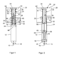
- FIG. 1 there may be seen part of an injection device comprising a drive mechanism in accordance with a first embodiment of the present invention, indicated generally at 10, and a medicament cartridge 12.
- the injection device will comprise a main housing and a needle unit including a delivery member in the form of a hollow needle which can be secured to a first end of the main housing.
- a medicament cartridge 12 having a first end 14 and a second end 15 may be stored in the main housing.
- the needle unit When the needle unit is in place, the needle unit pierces a flexible membrane 16 at the second end 15 of the medicament cartridge 12.
- a displaceable bung 18 is located at the first end of the medicament cartridge 12 when the cartridge is full as shown in Figure 1 .
- a cover (also not shown) may be provided over the first end of the main housing to protect the needle unit from damage and a user from inadvertent pricking by the needle. The cover also provides a discrete appearance for the injection device.
- the drive mechanism comprises a base member 20, a first drive member 22, a second drive member 24, a piston member 26, a control device (indicated schematically at 28 in Fig. 2 ), and a drive means, indicated generally at 30.
- the base member 20 may form part of the main housing of the injection device and has a planar portion 32, a mounting tab 34 projecting from the planar portion 32 for supporting one end of the first drive member 22 and an annular guide 35 for slidingly supporting the second drive member 24.
- the first drive member 22 has a mounting portion 33 at one end which can be attached to the mounting tab 34 of the base member such that the first drive member is fixed both axially and rotationally relative to the base member.
- the first drive member also has a spigot portion 36 that extends axially from the mounting portion 33 towards the medicament cartridge.
- a screw thread 38 is formed on the outer surface of the spigot portion 36 over most of its length.
- the second drive member 24 is in the form of a generally annular sleeve and has a first bore portion 40 that extends over the majority of its length.
- a first internal screw thread (not shown) is formed on the surface of the first bore portion for engagement with the thread 38 on the outer surface of the spigot portion 36 of the first drive member 22. The arrangement is such that rotation of the second drive member 24 results in the second drive member advancing axially relative to the first drive member towards the second end 15 of the medicament cartridge 12 along the thread 38.
- the end of the second drive member 24 closest to the medicament cartridge 12 is partially closed off by means of a wall 42 in which is formed a second bore portion 44 of smaller diameter than the first bore portion 40.
- a second internal thread (also not shown) is formed on the surface of the second bore portion 44 for engagement with a corresponding thread 46 formed on a piston rod 48 of the piston member 26.
- the screw thread 46 on the piston rod 48 and the second internal thread in the second bore portion 44 of the second drive member are arranged such that rotation of the second drive member relative to the piston member in the direction of arrow A in Figure 3 results in the piston member 26 advancing axially towards the second end 15 of medicament cartridge relative to the second drive member 24.
- thread 38 on the spigot portion 36 of the first drive member 22 and the thread 46 on the piston rod 48 are of opposite hand.
- the outer surface of the second drive member 24 is slidingly received within the annular guide 35 of the base member which acts to support the second drive member24 and to guide its movement in the axial direction.
- a plurality of axial splines are provided on the outer surface of the second drive member for engagement with a worm gear that forms part of the drive means 30 for rotating the second drive member as will be described in more detail below.
- the piston member 26 comprises a piston head 54 which can be received within the medicament cartridge 12 for contact with the bung 18.
- the piston rod 48 extends axially away from the piston head 54 towards the first drive member22 and is in screw threaded engagement with the second bore portion 44 of the second drive member 24 as has been described above.
- An elongate support member 56 interconnects the first drive member and the piston member and has a first, relatively short portion 58 and a second, relatively long portion 60.
- the first portion 58 is dimensioned so as to be slidingly received within a bore 62 formed in the spigot portion 36 of the first drive member 22.
- the second portion 60 of the support member 56 is dimensioned so as to be slidingly received within a bore 64 formed in the piston rod 48.
- the profiles of the first portion 58 of the support member and the bore 62 in the first drive member are selected so that the support member 56 cannot rotate relative to the first drive member 22.
- the outer profile of the second portion 60 of the support member 56 and the bore 64 in the piston rod are selected so that the piston member 26 cannot rotate relative to the support member 56.
- the support member 56 acts as an internal key for preventing the piston member26 from rotating relative to the first drive member 22 when the second drive member 24 is rotated.
- the bore 62 in the first drive member and the piston rod 48 are sized so that the piston rod 48 can be received within the bore 62 when the drive mechanism is fully retracted.
- Rotation of the second drive member 24 is carried out by the drive means 30.
- the drive means 30 comprises an electric motor 66, a gear train indicated generally at 68, a control device (not shown in the figures), and a power source in the form of a battery which provides power for the motor 66 and the control device by means of cables (not shown).
- the electric motor 66 is mounted to the base member 20 adjacent to the second drive member 24 and with the axis of its output shaft arranged generally perpendicular to the axis of rotation of the second drive member 24.
- Drive is transmitted from the electric motor 66 to the second drive member by means of the gear train 68 which includes a first, relatively small gearwheel mounted to the output shaft of the electric motor 66, a second, relatively large gear wheel in mesh with the first gearwheel, and the worm: gear which is mounted for rotation with the second gear wheel.
- the worm gear is supported for rotation about an axis that is generally parallel to the axis of rotation of the output shaft of the electric motor 66 by means of a pair of flanges projecting from the annular guide 35 of the base member 20.
- the worm gear has a spigot portion at either end, each spigot portion being received in a hole in a respective one of the flanges.
- the worm gear engages with the splines on the second drive member 24 through an opening in the wall of he annular guide 35.
- Part of the second gear wheel is accommodated in a recess provided in the base of the annular guide 35, to enable the worm gear to be positioned adjacent the second drive member 24. It will also be noted that the second drive member 24 effectively forms the final gear in the gear train.
- the piston head 54 contacts the bung 18 to move the bung towards the second end of the medicament cartridge to expel medicament.
- the piston member 26 can be caused to advance towards the second end 15 of the medicament cartridge by a predetermined amount in order to expel a predetermined dose of medicament in a controlled manner.
- Rotation of the output shaft of the motor 66 in a second direction opposite to the first will result in the second drive member 24 being rotated relative to the first drive member 22 in a direction opposite to the direction of arrow A in Figure 3. This will cause the piston member 26 and the second drive member 24 to be moved axially away from the second end 15 of the medicament cartridge, thus retracting the drive mechanism.
- the device 28 may include a microprocessor (not shown) and a user interface having a display through which information can be displayed to the user and input means by which a user can input instructions, for example to set a required dose of the medicament (also not shown).
- FIG. 1 the injection device is shown with a medicament cartridge 12 in position.
- the medicament cartridge 12 is full, so that the bung 18 is positioned close to the first end 14 of the cartridge and the drive mechanism is fully retracted.
- the spigot portion 36 of the first drive member is almost fully received within the second drive member 24 and the piston rod 48 is almost fully received within the bore 62 of the first drive member and the support member 56 is accommodated within the bores 62, 64 of the first drive member and the piston rod 48, respectively.
- the control device determines the length of time the motor 66 must be operated in the first direction in order to move the piston member axially towards the second end 15 of the cartridge by an amount that will deliver the required dose.
- the above sequence can be repeated a number of times to administer medicament to a user until the medicament cartridge is empty or until it has insufficient medicament to deliver a predetermined minimum dose.
- the drive mechanism will be fully extended in the maximum dispense position as shown in Figure 3.
- the electric motor 66 is operated in the reverse direction to move the piston member 26 and the second drive member 24 axially in a direction away from the second end 15 of the medicament cartridge 12 until the drive mechanism is fully retracted as shown in Figure 1 . This can be done in response to an input from a user or automatically by the control device when it detects that the medicament cartridge 12 is empty or has insufficient medicament to deliver the predetermined minimum dose.
- the empty medicament cartridge 12 can then be removed and replaced by a new cartridge.
- the spigot portion 36 of the first drive member is formed integrally with the mounting tab 34 on the base member 20. Also formed integrally with the tab 34 and surrounding the spigot portion 36 is the annular guide 35. The annular guide 35 is spaced from the spigot portion 36 so that the second drive member 24 can be slidingly received in a gap formed between the annular guide 35 and the spigot portion 36.
- the drive means 30 comprises an electric motor 66 which is mounted to the base member 20 such that the axis of rotation of an output shaft of the motor is substantially parallel with the axis of rotation of the second drive member 24.
- Drive is transmitted from the electric motor to the second drive member 24 via a series of spur gears. Whilst most of the spur gears in the series have their axes of rotation aligned substantially parallel with the axis of rotation of the second drive member 24, it will be noted that the axis of rotation of the final spur gear 90 in the series is arranged at an angle to the axis of rotation of the second drive member 24.
- the final spur gear also has a spigot that is rotatably supported in a hole in a flange projecting from one side of the annular guide 35.
- the drive mechanism 10 is constructed and operates in the same manner as the guide mechanism 10 described above in relation to Figures 1 to 2 .
- the inventive drive arrangement is very compact when fully retracted but is capable of being extended so as to move the bung 18 to the maximum dispense position.
- an internal key or support member 56 can be used to prevent the piston member 26 from rotating. This arrangement is simpler than that used in known telescopic, threaded drive mechanisms for injection devices in which additional external sleeves are used to prevent the piston member or other components from rotating.
- the term "medicament”, as used herein, means a pharmaceutical formulation containing at least one pharmaceutically active compound, wherein in one embodiment the pharmaceutically active compound has a molecular weight up to 1500 Da and/or is a peptide, a proteine, a polysaccharide, a vaccine, a DNA, a RNA, a antibody, an enzyme, an antibody, a hormone or an oligonucleotide, or a mixture of the above-mentioned pharmaceutically active compound, wherein in a further embodiment the pharmaceutically active compound is useful for the treatment and/or prophylaxis of diabetes mellitus or complications associated with diabetes mellitus such as diabetic retinopathy, thromboembolism disorders such as deep vein or pulmonary thromboembolism, acute coronary syndrome (ACS), angina, myocardial infarction, cancer, macular degeneration, inflammation, hay fever, atherosclerosis and/or rheumatoid arthritis, wherein in a further embodiment the pharmaceutically active
- Insulin analogues are for example Gly(A21), Arg(B31), Arg(B32) human insulin; Lys(B3), Glu(B29) human insulin; Lys(B28), Pro(B29) human insulin; Asp(B28) human insulin; human insulin, wherein proline in position B28 is replaced by Asp, Lys, Leu, Val or Ala and wherein in position B29 Lys may be replaced by Pro; Ala(B26) human insulin; Des(B28-B30) human insulin; Des(B27) human insulin and Des(B30) human insulin.
- Insulin derivates are for example B29-N-myristoyl-des(B30) human insulin; B29-N-palmitoyl-des(B30) human insulin; B29-N-myristoyl human insulin; B29-N-palmitoyl human insulin; B28-N-myristoyl LysB28ProB29 human insulin; B28-N-palmitoyl-LysB28ProB29 human insulin; B30-N-myristoyl-ThrB29LysB30 human insulin; B30-N-palmitoyl- ThrB29LysB30 human insulin; B29-N-(N-palmitoyl-Y-glutamyl)-des(B30) human insulin; B29-N-(N-lithocholyl-Y-glutamyl)-des(B30) human insulin; B29-N-( ⁇ -carboxyheptadecanoyl)-des(B30) human insulin and B29-N-( ⁇ -carbox
- Exendin-4 for example means Exendin-4(1-39), a peptide of the sequence H His-Gly-Glu-Gly-Thr-Phe-Thr-Ser-Asp-Leu-Ser-Lys-Gln-Met-Glu-Glu-Glu-Ala-Val-Arg-Leu-Phe-Ile-Glu-Trp-Leu-Lys-Asn-Gly-Gly-Pro-Ser-Ser-Gly-Ala-Pro-Pro-Pro-Ser-NH2.
- Exendin-4 derivatives are for example selected from the following list of compounds:
- Hormones are for example hypophysis hormones or hypothalamus hormones or regulatory active peptides and their antagonists as listed in Rote Liste, ed. 2008, Chapter 50 , such as Gonadotropine (Follitropin, Lutropin, Choriongonadotropin, Menotropin), Somatropine (Somatropin), Desmopressin, Terlipressin, Gonadorelin, Triptorelin, Leuprorelin, Buserelin, Nafarelin, Goserelin.
- Gonadotropine Follitropin, Lutropin, Choriongonadotropin, Menotropin
- Somatropine Somatropin
- Desmopressin Terlipressin
- Gonadorelin Triptorelin
- Leuprorelin Buserelin
- Nafarelin Goserelin.
- a polysaccharide is for example a glucosaminoglycane, a hyaluronic acid, a heparin, a low molecular weight heparin or an ultra low molecular weight heparin or a derivative thereof, or a sulphated, e.g. a poly-sulphated form of the above-mentioned polysaccharides, and/or a pharmaceutically acceptable salt thereof.
- An example of a pharmaceutically acceptable salt of a poly-sulphated low molecular weight heparin is enoxaparin sodium.
- Pharmaceutically acceptable salts are for example acid addition salts and basic salts.
- Acid addition salts are e.g. HCl or HBr salts.
- Basic salts are e.g. salts having a cation selected from alkali or alkaline, e.g. Na+, or K+, or Ca2+, or an ammonium ion N+(R1)(R2)(R3)(R4), wherein R1 to R4 independently of each other mean: hydrogen, an optionally substituted C1 C6-alkyl group, an optionally substituted C2-C6-alkenyl group, an optionally substituted C6-C10-aryl group, or an optionally substituted C6-C10-heteroaryl group.
- solvates are for example hydrates.
Landscapes
- Health & Medical Sciences (AREA)
- Vascular Medicine (AREA)
- Engineering & Computer Science (AREA)
- Anesthesiology (AREA)
- Biomedical Technology (AREA)
- Heart & Thoracic Surgery (AREA)
- Hematology (AREA)
- Life Sciences & Earth Sciences (AREA)
- Animal Behavior & Ethology (AREA)
- General Health & Medical Sciences (AREA)
- Public Health (AREA)
- Veterinary Medicine (AREA)
- Infusion, Injection, And Reservoir Apparatuses (AREA)
Priority Applications (1)
| Application Number | Priority Date | Filing Date | Title |
|---|---|---|---|
| EP10732713.2A EP2453955B1 (en) | 2009-07-15 | 2010-07-14 | Drive mechanism for an injection device and an injection device with such a drive mechanism |
Applications Claiming Priority (3)
| Application Number | Priority Date | Filing Date | Title |
|---|---|---|---|
| EP09009214 | 2009-07-15 | ||
| EP10732713.2A EP2453955B1 (en) | 2009-07-15 | 2010-07-14 | Drive mechanism for an injection device and an injection device with such a drive mechanism |
| PCT/EP2010/060127 WO2011006925A1 (en) | 2009-07-15 | 2010-07-14 | Drive mechanism for an injection device and an injection device with such a drive mechanism |
Publications (2)
| Publication Number | Publication Date |
|---|---|
| EP2453955A1 EP2453955A1 (en) | 2012-05-23 |
| EP2453955B1 true EP2453955B1 (en) | 2015-08-19 |
Family
ID=41480147
Family Applications (1)
| Application Number | Title | Priority Date | Filing Date |
|---|---|---|---|
| EP10732713.2A Active EP2453955B1 (en) | 2009-07-15 | 2010-07-14 | Drive mechanism for an injection device and an injection device with such a drive mechanism |
Country Status (10)
Cited By (2)
| Publication number | Priority date | Publication date | Assignee | Title |
|---|---|---|---|---|
| DE102015214088A1 (de) * | 2015-07-24 | 2017-01-26 | Vetter Pharma-Fertigung GmbH & Co. KG | Injektionseinrichtung und Verfahren zum Betreiben einer Injektionseinrichtung |
| DE102015214091A1 (de) * | 2015-07-24 | 2017-01-26 | Vetter Pharma-Fertigung GmbH & Co. KG | Injektionseinrichtung und Verfahren zum Betreiben einer Injektionseinrichtung |
Families Citing this family (31)
| Publication number | Priority date | Publication date | Assignee | Title |
|---|---|---|---|---|
| EP1476210B1 (en) | 2002-02-11 | 2008-09-24 | Antares Pharma, Inc. | Intradermal injector |
| DK1850892T4 (da) | 2005-01-24 | 2023-06-06 | Antares Pharma Inc | Forfyldt nål-assisteret sprøjtejetinjektor |
| WO2007131025A1 (en) | 2006-05-03 | 2007-11-15 | Antares Pharma, Inc. | Injector with adjustable dosing |
| US8251947B2 (en) | 2006-05-03 | 2012-08-28 | Antares Pharma, Inc. | Two-stage reconstituting injector |
| US9173997B2 (en) | 2007-10-02 | 2015-11-03 | Medimop Medical Projects Ltd. | External drug pump |
| ES2548447T3 (es) | 2008-03-10 | 2015-10-16 | Antares Pharma, Inc. | Dispositivo de seguridad para inyector |
| ES2738539T3 (es) | 2008-08-05 | 2020-01-23 | Antares Pharma Inc | Inyector de dosis múltiples |
| AU2010226442A1 (en) | 2009-03-20 | 2011-10-13 | Antares Pharma, Inc. | Hazardous agent injection system |
| CN103442748B (zh) * | 2011-02-19 | 2016-08-10 | 图什医疗有限公司 | 紧凑型医用泵装置 |
| US8496619B2 (en) | 2011-07-15 | 2013-07-30 | Antares Pharma, Inc. | Injection device with cammed ram assembly |
| US9220660B2 (en) | 2011-07-15 | 2015-12-29 | Antares Pharma, Inc. | Liquid-transfer adapter beveled spike |
| FI2822618T3 (fi) | 2012-03-06 | 2024-03-21 | Antares Pharma Inc | Esitäytetty injektioruisku laukeamisvoimaominaisuuden kera |
| CA2868500C (en) | 2012-04-06 | 2020-04-21 | Antares Pharma, Inc. | Needle assisted jet injection administration of testosterone compositions |
| WO2013169800A1 (en) | 2012-05-07 | 2013-11-14 | Antares Pharma, Inc. | Injection device with cammed ram assembly |
| CN102793966B (zh) * | 2012-08-02 | 2014-04-16 | 联合质量实业有限公司 | 便携可编程自动给药装置 |
| ES2763633T3 (es) | 2013-02-11 | 2020-05-29 | Antares Pharma Inc | Dispositivo de inyección por chorro asistido por aguja que tiene fuerza de disparo reducida |
| EP3572108A1 (en) | 2013-03-11 | 2019-11-27 | Antares Pharma, Inc. | Dosage injector with pinion system |
| WO2014165136A1 (en) | 2013-03-12 | 2014-10-09 | Antares Pharma, Inc. | Constant volume prefilled syringes and kits thereof |
| TWI689326B (zh) * | 2014-08-06 | 2020-04-01 | 加拿大商複製細胞生命科學公司 | 注射裝置 |
| JP6820104B2 (ja) | 2014-12-08 | 2021-01-27 | ジェネンテック, インコーポレイテッド | 多用途シリンジ基盤 |
| US10576207B2 (en) | 2015-10-09 | 2020-03-03 | West Pharma. Services IL, Ltd. | Angled syringe patch injector |
| CN108472438B (zh) | 2015-10-09 | 2022-01-28 | 西医药服务以色列分公司 | 至预填充的流体储存器的弯曲流体路径附加装置 |
| CN113041432B (zh) | 2016-01-21 | 2023-04-07 | 西医药服务以色列有限公司 | 包括视觉指示物的药剂输送装置 |
| JP6513297B2 (ja) | 2016-01-21 | 2019-05-22 | ウェスト ファーマ サービシーズ イスラエル リミテッド | 自動注射器、受け入れフレーム及び自動注射器におけるカートリッジの接続方法 |
| EP3405229A1 (en) | 2016-01-21 | 2018-11-28 | West Pharma. Services Il, Ltd. | Needle insertion and retraction mechanism |
| WO2017161076A1 (en) | 2016-03-16 | 2017-09-21 | Medimop Medical Projects Ltd. | Staged telescopic screw assembly having different visual indicators |
| JP6869327B2 (ja) | 2016-08-01 | 2021-05-12 | ウェスト ファーマ サービシーズ イスラエル リミテッド | 回転防止カートリッジ |
| EP3978047B1 (en) | 2016-08-01 | 2023-08-23 | West Pharma Services IL, Ltd | Partial door closure prevention spring |
| EP3315154B1 (de) | 2016-10-28 | 2021-07-07 | maxon international ag | Zweistufiger teleskopspindelantrieb |
| US11819666B2 (en) | 2017-05-30 | 2023-11-21 | West Pharma. Services IL, Ltd. | Modular drive train for wearable injector |
| CN111973841A (zh) * | 2019-05-22 | 2020-11-24 | 上海微创生命科技有限公司 | 输注设备 |
Family Cites Families (14)
| Publication number | Priority date | Publication date | Assignee | Title |
|---|---|---|---|---|
| GB2109690B (en) * | 1981-02-12 | 1985-02-20 | Robert Charles Turner | Dose metering plunger devices for use with syringes |
| US5269762A (en) | 1992-04-21 | 1993-12-14 | Sterling Winthrop, Inc. | Portable hand-held power assister device |
| DE19717107B4 (de) * | 1997-04-23 | 2005-06-23 | Disetronic Licensing Ag | System aus Behältnis und Antriebsvorrichtung für einen Kolben, der in dem ein Medikamentfluid enthaltenden Behältnis gehalten ist |
| US5893838A (en) * | 1997-08-15 | 1999-04-13 | Therox, Inc. | System and method for high pressure delivery of gas-supersaturated fluids |
| TW445157B (en) * | 1998-01-30 | 2001-07-11 | Novo Nordisk As | An injection syringe |
| US6248093B1 (en) * | 1998-10-29 | 2001-06-19 | Minimed Inc. | Compact pump drive system |
| ES2258469T3 (es) * | 1999-08-05 | 2006-09-01 | Becton Dickinson And Company | Lapiz de administracion de medicacion. |
| US6716198B2 (en) * | 2000-05-18 | 2004-04-06 | Novo Nordisk A/S | Injection device |
| BRPI0411212A (pt) * | 2003-06-09 | 2006-07-18 | Nipro Diabetes Systems Inc | sistema de liberação de lìquido |
| JP4549079B2 (ja) * | 2004-03-05 | 2010-09-22 | パナソニック株式会社 | 医療用投与器具 |
| US7670315B2 (en) * | 2005-01-21 | 2010-03-02 | Medrad, Inc. | Injectors, injector systems and methods for injecting fluids |
| ATE519513T1 (de) * | 2005-07-08 | 2011-08-15 | Novo Nordisk As | Injektionsvorrichtung |
| DE102006004563A1 (de) * | 2006-01-17 | 2007-07-19 | Tecpharma Licensing Ag | Ausfahrbarer Dosierknopf |
| DE102006038103B4 (de) * | 2006-08-14 | 2017-02-23 | Tecpharma Licensing Ag | Injektionsvorrichtung mit variabler Gewindeführung |
-
2010
- 2010-07-14 DK DK10732713.2T patent/DK2453955T3/en active
- 2010-07-14 BR BR112012000795A patent/BR112012000795A2/pt not_active IP Right Cessation
- 2010-07-14 CA CA2765899A patent/CA2765899A1/en not_active Abandoned
- 2010-07-14 CN CN201080030691XA patent/CN102470213A/zh active Pending
- 2010-07-14 EP EP10732713.2A patent/EP2453955B1/en active Active
- 2010-07-14 JP JP2012520023A patent/JP5701871B2/ja active Active
- 2010-07-14 WO PCT/EP2010/060127 patent/WO2011006925A1/en active Application Filing
- 2010-07-14 AU AU2010272600A patent/AU2010272600A1/en not_active Abandoned
- 2010-07-14 US US13/384,049 patent/US8517992B2/en active Active
-
2012
- 2012-01-08 IL IL217420A patent/IL217420A0/en unknown
Cited By (2)
| Publication number | Priority date | Publication date | Assignee | Title |
|---|---|---|---|---|
| DE102015214088A1 (de) * | 2015-07-24 | 2017-01-26 | Vetter Pharma-Fertigung GmbH & Co. KG | Injektionseinrichtung und Verfahren zum Betreiben einer Injektionseinrichtung |
| DE102015214091A1 (de) * | 2015-07-24 | 2017-01-26 | Vetter Pharma-Fertigung GmbH & Co. KG | Injektionseinrichtung und Verfahren zum Betreiben einer Injektionseinrichtung |
Also Published As
| Publication number | Publication date |
|---|---|
| IL217420A0 (en) | 2012-02-29 |
| BR112012000795A2 (pt) | 2016-02-23 |
| EP2453955A1 (en) | 2012-05-23 |
| WO2011006925A1 (en) | 2011-01-20 |
| CN102470213A (zh) | 2012-05-23 |
| US8517992B2 (en) | 2013-08-27 |
| US20120220941A1 (en) | 2012-08-30 |
| JP2012532721A (ja) | 2012-12-20 |
| JP5701871B2 (ja) | 2015-04-15 |
| DK2453955T3 (en) | 2015-11-23 |
| AU2010272600A1 (en) | 2012-02-02 |
| CA2765899A1 (en) | 2011-01-20 |
Similar Documents
| Publication | Publication Date | Title |
|---|---|---|
| EP2453955B1 (en) | Drive mechanism for an injection device and an injection device with such a drive mechanism | |
| US8961020B2 (en) | Thrust bearing assembly, drive train, and medicament delivery device | |
| CA2762043C (en) | Dose setting mechanism for a drug delivery device | |
| EP2512563B1 (en) | Dose setting mechanism with maximum dose limiting element | |
| EP2475410B1 (en) | Drive mechanism for a medication delivery device and medication delivery device | |
| US9089656B2 (en) | Spindle and bearing combination and drug delivery device | |
| US20120209200A1 (en) | Drive Assembly for a Pen-Type Injector and Pen-Type Injector with a Drive Assembly | |
| EP2482887B1 (en) | Drive mechanism for a drug delivery device | |
| EP2470150A2 (en) | Reminder device for drug delivery devices | |
| HK1177704B (en) | Dose setting mechanism with maximum dose limiting element | |
| HK1177704A (en) | Dose setting mechanism with maximum dose limiting element | |
| HK1168056B (en) | Spindle and bearing combination and drug delivery device | |
| HK1168056A (en) | Spindle and bearing combination and drug delivery device | |
| HK1168810B (en) | Dose setting mechanism for a drug delivery device for limiting dose setting corresponding to amount of medicament left | |
| HK1168810A (en) | Dose setting mechanism for a drug delivery device for limiting dose setting corresponding to amount of medicament left | |
| HK1169054B (en) | Drive mechanism for a drug delivery device |
Legal Events
| Date | Code | Title | Description |
|---|---|---|---|
| PUAI | Public reference made under article 153(3) epc to a published international application that has entered the european phase |
Free format text: ORIGINAL CODE: 0009012 |
|
| 17P | Request for examination filed |
Effective date: 20120215 |
|
| AK | Designated contracting states |
Kind code of ref document: A1 Designated state(s): AL AT BE BG CH CY CZ DE DK EE ES FI FR GB GR HR HU IE IS IT LI LT LU LV MC MK MT NL NO PL PT RO SE SI SK SM TR |
|
| DAX | Request for extension of the european patent (deleted) | ||
| REG | Reference to a national code |
Ref country code: HK Ref legal event code: DE Ref document number: 1170965 Country of ref document: HK |
|
| GRAP | Despatch of communication of intention to grant a patent |
Free format text: ORIGINAL CODE: EPIDOSNIGR1 |
|
| INTG | Intention to grant announced |
Effective date: 20150126 |
|
| GRAS | Grant fee paid |
Free format text: ORIGINAL CODE: EPIDOSNIGR3 |
|
| GRAA | (expected) grant |
Free format text: ORIGINAL CODE: 0009210 |
|
| AK | Designated contracting states |
Kind code of ref document: B1 Designated state(s): AL AT BE BG CH CY CZ DE DK EE ES FI FR GB GR HR HU IE IS IT LI LT LU LV MC MK MT NL NO PL PT RO SE SI SK SM TR |
|
| REG | Reference to a national code |
Ref country code: GB Ref legal event code: FG4D |
|
| REG | Reference to a national code |
Ref country code: CH Ref legal event code: EP |
|
| REG | Reference to a national code |
Ref country code: IE Ref legal event code: FG4D |
|
| REG | Reference to a national code |
Ref country code: AT Ref legal event code: REF Ref document number: 743347 Country of ref document: AT Kind code of ref document: T Effective date: 20150915 |
|
| REG | Reference to a national code |
Ref country code: DE Ref legal event code: R096 Ref document number: 602010026814 Country of ref document: DE |
|
| REG | Reference to a national code |
Ref country code: DK Ref legal event code: T3 Effective date: 20151117 |
|
| REG | Reference to a national code |
Ref country code: AT Ref legal event code: MK05 Ref document number: 743347 Country of ref document: AT Kind code of ref document: T Effective date: 20150819 |
|
| REG | Reference to a national code |
Ref country code: LT Ref legal event code: MG4D |
|
| REG | Reference to a national code |
Ref country code: NL Ref legal event code: MP Effective date: 20150819 |
|
| PG25 | Lapsed in a contracting state [announced via postgrant information from national office to epo] |
Ref country code: GR Free format text: LAPSE BECAUSE OF FAILURE TO SUBMIT A TRANSLATION OF THE DESCRIPTION OR TO PAY THE FEE WITHIN THE PRESCRIBED TIME-LIMIT Effective date: 20151120 Ref country code: LT Free format text: LAPSE BECAUSE OF FAILURE TO SUBMIT A TRANSLATION OF THE DESCRIPTION OR TO PAY THE FEE WITHIN THE PRESCRIBED TIME-LIMIT Effective date: 20150819 Ref country code: NO Free format text: LAPSE BECAUSE OF FAILURE TO SUBMIT A TRANSLATION OF THE DESCRIPTION OR TO PAY THE FEE WITHIN THE PRESCRIBED TIME-LIMIT Effective date: 20151119 Ref country code: LV Free format text: LAPSE BECAUSE OF FAILURE TO SUBMIT A TRANSLATION OF THE DESCRIPTION OR TO PAY THE FEE WITHIN THE PRESCRIBED TIME-LIMIT Effective date: 20150819 Ref country code: FI Free format text: LAPSE BECAUSE OF FAILURE TO SUBMIT A TRANSLATION OF THE DESCRIPTION OR TO PAY THE FEE WITHIN THE PRESCRIBED TIME-LIMIT Effective date: 20150819 |
|
| PG25 | Lapsed in a contracting state [announced via postgrant information from national office to epo] |
Ref country code: IS Free format text: LAPSE BECAUSE OF FAILURE TO SUBMIT A TRANSLATION OF THE DESCRIPTION OR TO PAY THE FEE WITHIN THE PRESCRIBED TIME-LIMIT Effective date: 20151219 Ref country code: ES Free format text: LAPSE BECAUSE OF FAILURE TO SUBMIT A TRANSLATION OF THE DESCRIPTION OR TO PAY THE FEE WITHIN THE PRESCRIBED TIME-LIMIT Effective date: 20150819 Ref country code: PT Free format text: LAPSE BECAUSE OF FAILURE TO SUBMIT A TRANSLATION OF THE DESCRIPTION OR TO PAY THE FEE WITHIN THE PRESCRIBED TIME-LIMIT Effective date: 20151221 Ref country code: PL Free format text: LAPSE BECAUSE OF FAILURE TO SUBMIT A TRANSLATION OF THE DESCRIPTION OR TO PAY THE FEE WITHIN THE PRESCRIBED TIME-LIMIT Effective date: 20150819 Ref country code: AT Free format text: LAPSE BECAUSE OF FAILURE TO SUBMIT A TRANSLATION OF THE DESCRIPTION OR TO PAY THE FEE WITHIN THE PRESCRIBED TIME-LIMIT Effective date: 20150819 Ref country code: SE Free format text: LAPSE BECAUSE OF FAILURE TO SUBMIT A TRANSLATION OF THE DESCRIPTION OR TO PAY THE FEE WITHIN THE PRESCRIBED TIME-LIMIT Effective date: 20150819 |
|
| PG25 | Lapsed in a contracting state [announced via postgrant information from national office to epo] |
Ref country code: NL Free format text: LAPSE BECAUSE OF FAILURE TO SUBMIT A TRANSLATION OF THE DESCRIPTION OR TO PAY THE FEE WITHIN THE PRESCRIBED TIME-LIMIT Effective date: 20150819 |
|
| PG25 | Lapsed in a contracting state [announced via postgrant information from national office to epo] |
Ref country code: SK Free format text: LAPSE BECAUSE OF FAILURE TO SUBMIT A TRANSLATION OF THE DESCRIPTION OR TO PAY THE FEE WITHIN THE PRESCRIBED TIME-LIMIT Effective date: 20150819 Ref country code: IT Free format text: LAPSE BECAUSE OF FAILURE TO SUBMIT A TRANSLATION OF THE DESCRIPTION OR TO PAY THE FEE WITHIN THE PRESCRIBED TIME-LIMIT Effective date: 20150819 Ref country code: EE Free format text: LAPSE BECAUSE OF FAILURE TO SUBMIT A TRANSLATION OF THE DESCRIPTION OR TO PAY THE FEE WITHIN THE PRESCRIBED TIME-LIMIT Effective date: 20150819 Ref country code: CZ Free format text: LAPSE BECAUSE OF FAILURE TO SUBMIT A TRANSLATION OF THE DESCRIPTION OR TO PAY THE FEE WITHIN THE PRESCRIBED TIME-LIMIT Effective date: 20150819 |
|
| REG | Reference to a national code |
Ref country code: DE Ref legal event code: R097 Ref document number: 602010026814 Country of ref document: DE |
|
| PG25 | Lapsed in a contracting state [announced via postgrant information from national office to epo] |
Ref country code: RO Free format text: LAPSE BECAUSE OF FAILURE TO SUBMIT A TRANSLATION OF THE DESCRIPTION OR TO PAY THE FEE WITHIN THE PRESCRIBED TIME-LIMIT Effective date: 20150819 |
|
| REG | Reference to a national code |
Ref country code: FR Ref legal event code: PLFP Year of fee payment: 7 |
|
| PLBE | No opposition filed within time limit |
Free format text: ORIGINAL CODE: 0009261 |
|
| STAA | Information on the status of an ep patent application or granted ep patent |
Free format text: STATUS: NO OPPOSITION FILED WITHIN TIME LIMIT |
|
| 26N | No opposition filed |
Effective date: 20160520 |
|
| PG25 | Lapsed in a contracting state [announced via postgrant information from national office to epo] |
Ref country code: SI Free format text: LAPSE BECAUSE OF FAILURE TO SUBMIT A TRANSLATION OF THE DESCRIPTION OR TO PAY THE FEE WITHIN THE PRESCRIBED TIME-LIMIT Effective date: 20150819 |
|
| PG25 | Lapsed in a contracting state [announced via postgrant information from national office to epo] |
Ref country code: BE Free format text: LAPSE BECAUSE OF FAILURE TO SUBMIT A TRANSLATION OF THE DESCRIPTION OR TO PAY THE FEE WITHIN THE PRESCRIBED TIME-LIMIT Effective date: 20150819 |
|
| PG25 | Lapsed in a contracting state [announced via postgrant information from national office to epo] |
Ref country code: MC Free format text: LAPSE BECAUSE OF FAILURE TO SUBMIT A TRANSLATION OF THE DESCRIPTION OR TO PAY THE FEE WITHIN THE PRESCRIBED TIME-LIMIT Effective date: 20150819 |
|
| REG | Reference to a national code |
Ref country code: IE Ref legal event code: MM4A |
|
| REG | Reference to a national code |
Ref country code: FR Ref legal event code: PLFP Year of fee payment: 8 |
|
| PG25 | Lapsed in a contracting state [announced via postgrant information from national office to epo] |
Ref country code: IE Free format text: LAPSE BECAUSE OF NON-PAYMENT OF DUE FEES Effective date: 20160714 |
|
| PG25 | Lapsed in a contracting state [announced via postgrant information from national office to epo] |
Ref country code: LU Free format text: LAPSE BECAUSE OF NON-PAYMENT OF DUE FEES Effective date: 20160714 |
|
| PG25 | Lapsed in a contracting state [announced via postgrant information from national office to epo] |
Ref country code: SM Free format text: LAPSE BECAUSE OF FAILURE TO SUBMIT A TRANSLATION OF THE DESCRIPTION OR TO PAY THE FEE WITHIN THE PRESCRIBED TIME-LIMIT Effective date: 20150819 Ref country code: HU Free format text: LAPSE BECAUSE OF FAILURE TO SUBMIT A TRANSLATION OF THE DESCRIPTION OR TO PAY THE FEE WITHIN THE PRESCRIBED TIME-LIMIT; INVALID AB INITIO Effective date: 20100714 Ref country code: CY Free format text: LAPSE BECAUSE OF FAILURE TO SUBMIT A TRANSLATION OF THE DESCRIPTION OR TO PAY THE FEE WITHIN THE PRESCRIBED TIME-LIMIT Effective date: 20150819 |
|
| REG | Reference to a national code |
Ref country code: FR Ref legal event code: PLFP Year of fee payment: 9 |
|
| PG25 | Lapsed in a contracting state [announced via postgrant information from national office to epo] |
Ref country code: MT Free format text: LAPSE BECAUSE OF NON-PAYMENT OF DUE FEES Effective date: 20160731 Ref country code: HR Free format text: LAPSE BECAUSE OF FAILURE TO SUBMIT A TRANSLATION OF THE DESCRIPTION OR TO PAY THE FEE WITHIN THE PRESCRIBED TIME-LIMIT Effective date: 20150819 Ref country code: MK Free format text: LAPSE BECAUSE OF FAILURE TO SUBMIT A TRANSLATION OF THE DESCRIPTION OR TO PAY THE FEE WITHIN THE PRESCRIBED TIME-LIMIT Effective date: 20150819 |
|
| PG25 | Lapsed in a contracting state [announced via postgrant information from national office to epo] |
Ref country code: BG Free format text: LAPSE BECAUSE OF FAILURE TO SUBMIT A TRANSLATION OF THE DESCRIPTION OR TO PAY THE FEE WITHIN THE PRESCRIBED TIME-LIMIT Effective date: 20150819 |
|
| PG25 | Lapsed in a contracting state [announced via postgrant information from national office to epo] |
Ref country code: AL Free format text: LAPSE BECAUSE OF FAILURE TO SUBMIT A TRANSLATION OF THE DESCRIPTION OR TO PAY THE FEE WITHIN THE PRESCRIBED TIME-LIMIT Effective date: 20150819 |
|
| PGFP | Annual fee paid to national office [announced via postgrant information from national office to epo] |
Ref country code: SE Payment date: 20180725 Year of fee payment: 8 |
|
| REG | Reference to a national code |
Ref country code: HK Ref legal event code: WD Ref document number: 1170965 Country of ref document: HK |
|
| PG25 | Lapsed in a contracting state [announced via postgrant information from national office to epo] |
Ref country code: TR Free format text: LAPSE BECAUSE OF NON-PAYMENT OF DUE FEES Effective date: 20190714 |
|
| PGFP | Annual fee paid to national office [announced via postgrant information from national office to epo] |
Ref country code: DE Payment date: 20240604 Year of fee payment: 15 |
|
| PGFP | Annual fee paid to national office [announced via postgrant information from national office to epo] |
Ref country code: DK Payment date: 20240712 Year of fee payment: 15 |
|
| PGFP | Annual fee paid to national office [announced via postgrant information from national office to epo] |
Ref country code: CH Payment date: 20240801 Year of fee payment: 15 |
|
| PGFP | Annual fee paid to national office [announced via postgrant information from national office to epo] |
Ref country code: GB Payment date: 20250529 Year of fee payment: 16 |
|
| PGFP | Annual fee paid to national office [announced via postgrant information from national office to epo] |
Ref country code: FR Payment date: 20250610 Year of fee payment: 16 |