EP2453178A2 - Control device for a heating system and heating system - Google Patents
Control device for a heating system and heating system Download PDFInfo
- Publication number
- EP2453178A2 EP2453178A2 EP11189152A EP11189152A EP2453178A2 EP 2453178 A2 EP2453178 A2 EP 2453178A2 EP 11189152 A EP11189152 A EP 11189152A EP 11189152 A EP11189152 A EP 11189152A EP 2453178 A2 EP2453178 A2 EP 2453178A2
- Authority
- EP
- European Patent Office
- Prior art keywords
- heat exchanger
- building
- control device
- temperature
- rooms
- Prior art date
- Legal status (The legal status is an assumption and is not a legal conclusion. Google has not performed a legal analysis and makes no representation as to the accuracy of the status listed.)
- Granted
Links
- 238000010438 heat treatment Methods 0.000 title claims abstract description 53
- 239000012530 fluid Substances 0.000 claims abstract description 29
- 230000003134 recirculating effect Effects 0.000 claims abstract description 3
- 230000000977 initiatory effect Effects 0.000 claims 1
- 238000011144 upstream manufacturing Methods 0.000 claims 1
- 238000001816 cooling Methods 0.000 description 5
- 230000001276 controlling effect Effects 0.000 description 3
- 230000004913 activation Effects 0.000 description 2
- 230000001105 regulatory effect Effects 0.000 description 2
- XLYOFNOQVPJJNP-UHFFFAOYSA-N water Substances O XLYOFNOQVPJJNP-UHFFFAOYSA-N 0.000 description 2
- 230000003247 decreasing effect Effects 0.000 description 1
- 230000000694 effects Effects 0.000 description 1
- 230000003760 hair shine Effects 0.000 description 1
- 239000002689 soil Substances 0.000 description 1
- 230000036962 time dependent Effects 0.000 description 1
- 238000009423 ventilation Methods 0.000 description 1
Images


Classifications
-
- F—MECHANICAL ENGINEERING; LIGHTING; HEATING; WEAPONS; BLASTING
- F24—HEATING; RANGES; VENTILATING
- F24D—DOMESTIC- OR SPACE-HEATING SYSTEMS, e.g. CENTRAL HEATING SYSTEMS; DOMESTIC HOT-WATER SUPPLY SYSTEMS; ELEMENTS OR COMPONENTS THEREFOR
- F24D19/00—Details
- F24D19/10—Arrangement or mounting of control or safety devices
- F24D19/1006—Arrangement or mounting of control or safety devices for water heating systems
- F24D19/1009—Arrangement or mounting of control or safety devices for water heating systems for central heating
-
- F—MECHANICAL ENGINEERING; LIGHTING; HEATING; WEAPONS; BLASTING
- F24—HEATING; RANGES; VENTILATING
- F24D—DOMESTIC- OR SPACE-HEATING SYSTEMS, e.g. CENTRAL HEATING SYSTEMS; DOMESTIC HOT-WATER SUPPLY SYSTEMS; ELEMENTS OR COMPONENTS THEREFOR
- F24D3/00—Hot-water central heating systems
- F24D3/08—Hot-water central heating systems in combination with systems for domestic hot-water supply
Definitions
- the application relates to a control device for a heating system and further relates to a heating system provided with and controlled by a control device.
- the room temperature is often regulated by means of controlled or regulated throttling of the fluid heating medium (heat exchange medium) being transported, such as water, that is fed into the radiators of each room, or in concrete slabs or other types of surface heating elements that form the walls, floors, and/or ceilings of the rooms.
- heat exchange medium fluid heating medium
- the optimal flow rate of the fluid medium is often different in the various rooms of a building; it depends on the prescribed target temperature of the room (as a function of the time and day of the week), but also on the additional energy input or energy output due to sunlight, wind, soil temperature, manual or automatic ventilation, or other influences.
- the infeed of the fluid medium or its flow rate in the heating system of the room is conventionally throttled or interrupted. If this is not sufficient, then the room temperature can be decreased again by automatically ventilating the room. But even if the heated discharge air is recycled to recapture energy, then energy savings are limited. Particularly if heating is still performed in other rooms of the building, such on the north side or on the ground floor (that is the lowermost story above the ground) because the temperature there is below the provided target temperature, greater and more efficient energy savings would be desirable.
- the application provides a control device for controlling a heating system having at least one first heat exchanger disposed in a first part of a building, and at least one second heat exchanger disposed in a second part of a building. wherein the control device comprises at least the following:
- the control device uses the fluid medium not only for heating, but also for cooling. However, no active cooling is used; rather the fluid medium is exchanged between at rooms, groups of rooms, sides or other parts of buildings having different temperatures.
- the control device measures opposing deviations from the target temperature provided in the different parts of the building (like a temperature too high in first, overheated rooms of the building as opposed to a temperature too low in further, second subcooled rooms of the building) and uses the fluid medium itself to adjust the room temperature.
- the flow streams of the fluid medium are diverted, that is re-routed, in a way that differs from the flow scheme in conventional operation.
- the control device or its control station adjusts the heating system which it is a part of, such that a closed circuit of the fluid medium is established between a first and a second heat exchanger each associated with different parts of the building, which may for instance be different rooms, different groups of rooms, different floors or stories, or different sides of the building.
- each side of the two opposite sides of the building may comprise a room or a groups of rooms arranged at that respective side of the building and/or having windows at that respective side of the building).
- the medium circulates between both heat exchangers but remains separated or cut off from any remaining quantity of fluid medium and from active heat input.
- groups of first or second heat exchangers can also be provided, leading into a plurality of overheated or subcooled rooms at the same time.
- the circulating partial circuit arising from simple recirculation of the medium, cut off from the other heat exchangers of the arrangement of heat exchangers, is automatically initiated and maintained by the control device whenever and as long as the first part of the building is heated above its target temperature and the second part of the building at the same time is colder than its target temperature.
- this temperature compensation is initiated and executed at least when and/or as long as overheated rooms and other subcooled rooms are present in the same time in the building, and it is particularly initiated and executed between those rooms, groups of rooms, floors or sides of the building where the target temperature of the overheated rooms is greater than the target temperature of the subcooled rooms.
- the overheated rooms (excessively high temperature) is then cooled and the subcooled rooms are heated, exploiting merely the locally varying temperature of the fluid medium without consuming additional energy from a furnace, a heating or a cooling unit.
- temperature control can be effected merely by means of the continuous or intermittent recirculation of the fluid medium in the closed circuit between the first and the second heat exchanger.
- the local deviations from the target temperature in individual rooms or groups of rooms are thereby compensated for more quickly and efficiently, while saving more energy.
- the first part of the building in which the at least one first heat exchanger is disposed comprises a first room, a first group of rooms, a first story, or a first side of a building
- the second part of the building in which the at least one second heat exchanger is disposed comprises another second room, another second group of rooms, another second story, or another second side of a building, respectively.
- the first part and the second part are opposed to one another.
- the first part may comprise all rooms constituting the south side or façade of the building whereas the second part may comprise all rooms constituting the north side or façade of the building.
- the first part may comprise rooms on upper floors or stories whereas the second part may comprise rooms on lower floors or stories of the building, for instance.
- the first and second heat exchangers are arranged distant from one another and are particularly arranged in different, preferably opposite parts of a building.
- one single heat exchanger or group of heat exchangers is provided which is usable, at a time, either as the first or as the second heat exchanger, depending on whether the respective room is to be momentarily cooled or heated.
- the control device comprises just one single heat exchanger or group of heat exchangers in each room, which heat exchanger or group of heat exchangers is usable either as the at least one first heat exchanger or, alternatively, as the at least one second heat exchanger at a time.
- the heat exchangers installed in it or in its walls, its floor and/or its ceiling or its radiators temporarily can serves as the at least one first heat exchanger and, at other times, can serve as the at least one second heat exchanger, depending on whether the room is overheated or subcooled and on whether there are other rooms in the building which at the same time are subcooled or overheated.
- This preferably applies to all rooms of the building. Accordingly, there is no need to install two types of heat exchangers for heating and cooling (especially not in one and the same wall); instead the control station (particularly its distributor and/or its mixing valves) controls which heat exchangers are connected with one another, particularly in series, and thus effects cooling of the first and heating of the second room merely by circulation of the fluid medium.
- first and second heat exchangers preferably likewise apply to the first and second temperature sensors.
- first or, alternatively, second temperature sensors are installed in (and measure the temperature of) the first or, alternatively, second part of the building as defined above.
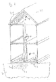
- Figure 1 shows a heating system 10 and a control device 20 according to a first embodiment, controlling the heating system 10.
- the rooms shown on the right in Figure 1 represent the rooms on the sunlit south side (first part of the building 21), while the rooms shown on the left in Figure 1 , for example, correspond to the cooler north side (second part of the building 22) of the building 25.
- Each of the building parts that can have separately controlled temperature can comprise a plurality of rooms, or just one room.
- the building 25 comprises surface heating elements 7, such as in the form of floors, ceilings, walls, or even the roof, permeated by heat exchanger lines.
- the heat exchangers 1, 2 disposed in the surface heating elements 7 are indicated by spiral shapes and further shown as dashed lines in the section plane; they are connected to the heating system 10, which can be disposed at an arbitrary location in the building and which is shown only schematically, as is the control device 20.
- the heating system 10 which can be disposed at an arbitrary location in the building and which is shown only schematically, as is the control device 20.
- the first temperature sensor 11 measures the time dependent actual temperature T1 in the first part of the building 21
- the second temperature sensor 12 measures the temperature T2 in the second part of the building 22. Both sensors are connected to the control device 20 by connecting lines or in some other manner.
- the control device 20 compares each of the current temperatures T1, T2 to the target temperature ST1, ST2 for each room or part of the building, and particularly checks whether the actual temperature T1 exceeds the first target temperature ST1 in the first part of the building 21. It further checks whether the actual temperature T2 in the second part of the building 22 is lower than the second target temperature ST2. Finally, the control device 20 also checks whether both events occur at the same time.
- the control device 20 initiates the heating system 10 to produce a closed circuit between the first 1 and the second heat exchanger 2, separated from the other heat exchangers of the arrangement of heat exchangers, and decoupled from further heat input from a heat source, such as a furnace of the heating system 10.
- the control device 20 further activates the circulating pump of the heating system 10, whereupon the medium circulates in the closed circuit formed by the first heat exchanger 1 and the second heat exchanger 2 (and optionally short connecting lines in the distributor).
- first target temperature ST1 is at least as high as the second target temperature ST2, so that each of the temperatures in the two rooms or parts of the building 21, 22 approach the corresponding target temperatures ST1, ST2 again.
- the rooms on the south side are thereby cooled and the rooms on the north side are heated, simply by circulating water or some other fluid medium in the heating system, without additional heating energy being consumed in the furnace or heating source.
- the first and the second heat exchanger 1, 2 can each also be a group of first and second heat exchangers 1, 2.
- the embodiment according to Figure 1 can further be combined with that according to Figure 2 .
- Figure 2 shows a heating system 10 and a control device 20 according to a second embodiment, controlling the heating system 10.
- the first heat exchanger 1 or the group of first heat exchangers 1 leads to the roof of the building 25.
- the second heat exchanger 2 or the group of second heat exchangers 2 leads to the floor of a lower story, or, as indicated by a first heat exchanger 2a shown in dashed lines, is located within a basement of the building (not shown) which may be provided beneath a floor slab of the ground story.
- First and second temperature sensors 11, 12 connected to the control device 20 are further indicated.
- the heating system 10 and the control device 20 function as in Figure 1 , with the difference that in Figure 2 a temperature compensation takes place between two parts of the building at different heights in or on the building.
- a temperature compensation takes place between two parts of the building at different heights in or on the building.
- the roof story on which the sun shines is cooled during the day, and the lowest story is heated as soon as the temperature T1 on the roof has risen above the first local target temperature ST1 (T1 > ST1) and the temperature T2 at the ground story is simultaneously lower than the lower local target temperature ST2 (T2 ⁇ ST2).
- FIG 3 shows a schematic representation of an embodiment example of the control device 20 and the heating system 10, by means of which, for example, the temperature in the rooms of the building of Figures 1 and 2 can be controlled.
- the control device 20 measures the temperatures in at least two parts of the building by means of the temperature sensors 11, 12.
- the control device 20 or its control station 15 checks whether the temperature T1 in a first 21 of the building parts is above the target value ST1 set for this part of the building 21. A corresponding check is made as to whether the temperature T2 in the second part of the building is below the target temperature ST2 there.
- the control device 20 or its control station 15 initiates the closed circuit of the fluid medium in the first and second heat exchanger 1, 2, in that the distributor 5 is initiated to separate these heat exchangers 1, 2 from the remaining heat exchangers 8 of the arrangement of heat exchangers 9 and also from the heating source 3 or the furnace.
- This is done by means of the schematically represented switching elements (14) and/or actuating lines 18, or in another manner, such as actuators or the like.
- a mixer valve 6 or a group of mixer valves 6 can thus be set.
- the circulating pump 4 is further switched on and maintained in operation by means of schematically represented switching elements 13 and/or activation lines 17, so that the fluid medium contained in the heat exchangers 1, 2 can circulate therein.
- the surface heating elements 7 having heat exchangers 1, 2 ( Figures 1 or 2 ) thereby adapt their temperatures, leading to the actual room temperature T1, T2 approaching each target temperature.
- the control device 20 or its control station 15 initiates the termination of the circulating closed circuit formed by the heat exchangers 1, 2 and sets the heating system 10 and the distributor 5 back to the original or previous operating settings.
Landscapes
- Engineering & Computer Science (AREA)
- Physics & Mathematics (AREA)
- Thermal Sciences (AREA)
- Chemical & Material Sciences (AREA)
- Combustion & Propulsion (AREA)
- Mechanical Engineering (AREA)
- General Engineering & Computer Science (AREA)
- Water Supply & Treatment (AREA)
- Steam Or Hot-Water Central Heating Systems (AREA)
- Domestic Hot-Water Supply Systems And Details Of Heating Systems (AREA)
Abstract
wherein the control device (20) comprises at least the following:
- at least one first temperature sensor (11) associated with the first heat exchanger (1) and measuring a temperature in the first part of the building (21),
- at least one second temperature sensor (12) associated with the second heat exchanger (2; 2a) and measuring a temperature in the second part of the building (22),
wherein the control device (20) comprises a control station (15) by which a temperature compensation can be initiated by simply recirculating a fluid medium to be used for heat exchange as a function of the temperatures (T1, T2) measured by the first (11) and the second temperature sensor (12), wherein an at least partial exchange of the fluid medium takes place between the first heat exchanger (1) and the second heat exchanger (2; 2a).
Description
- The application relates to a control device for a heating system and further relates to a heating system provided with and controlled by a control device.
- Frugal use of energy is critical to the economic efficiency of heating systems, particularly of heating systems for buildings. The room temperature is often regulated by means of controlled or regulated throttling of the fluid heating medium (heat exchange medium) being transported, such as water, that is fed into the radiators of each room, or in concrete slabs or other types of surface heating elements that form the walls, floors, and/or ceilings of the rooms.
- The optimal flow rate of the fluid medium is often different in the various rooms of a building; it depends on the prescribed target temperature of the room (as a function of the time and day of the week), but also on the additional energy input or energy output due to sunlight, wind, soil temperature, manual or automatic ventilation, or other influences.
- If a room is being heated but has ultimately reached and exceed its desired target temperature, the infeed of the fluid medium or its flow rate in the heating system of the room (or of its wall, ceiling, or floor) is conventionally throttled or interrupted. If this is not sufficient, then the room temperature can be decreased again by automatically ventilating the room. But even if the heated discharge air is recycled to recapture energy, then energy savings are limited. Particularly if heating is still performed in other rooms of the building, such on the north side or on the ground floor (that is the lowermost story above the ground) because the temperature there is below the provided target temperature, greater and more efficient energy savings would be desirable.
- There is thus a need for a control device by means of which a heating system can be operated in a way saving even more energy and by means fo which particularly local deviations from the target temperature in individual rooms or groups of rooms can be compensated for more quickly and efficiently.
- The application provides a control device for controlling a heating system having at least one first heat exchanger disposed in a first part of a building, and at least one second heat exchanger disposed in a second part of a building.
wherein the control device comprises at least the following: - at least one first temperature sensor associated with the first heat exchanger and measuring a temperature in the first part of the building,
- at least one second temperature sensor associated with the second heat exchanger and measuring a temperature in the second part of the building,
- The control device according to the application uses the fluid medium not only for heating, but also for cooling. However, no active cooling is used; rather the fluid medium is exchanged between at rooms, groups of rooms, sides or other parts of buildings having different temperatures. The control device measures opposing deviations from the target temperature provided in the different parts of the building (like a temperature too high in first, overheated rooms of the building as opposed to a temperature too low in further, second subcooled rooms of the building) and uses the fluid medium itself to adjust the room temperature. To this end, the flow streams of the fluid medium are diverted, that is re-routed, in a way that differs from the flow scheme in conventional operation.
- The control device or its control station adjusts the heating system which it is a part of, such that a closed circuit of the fluid medium is established between a first and a second heat exchanger each associated with different parts of the building, which may for instance be different rooms, different groups of rooms, different floors or stories, or different sides of the building. In case that the heat exchangers are associated with different, opposite sides of the building, each side of the two opposite sides of the building may comprise a room or a groups of rooms arranged at that respective side of the building and/or having windows at that respective side of the building). In the closed circuit established between the first and the second heat exchanger, the medium circulates between both heat exchangers but remains separated or cut off from any remaining quantity of fluid medium and from active heat input. In place of the first and second heat exchangers, groups of first or second heat exchangers can also be provided, leading into a plurality of overheated or subcooled rooms at the same time.
- The circulating partial circuit arising from simple recirculation of the medium, cut off from the other heat exchangers of the arrangement of heat exchangers, is automatically initiated and maintained by the control device whenever and as long as the first part of the building is heated above its target temperature and the second part of the building at the same time is colder than its target temperature. Preferably this temperature compensation is initiated and executed at least when and/or as long as overheated rooms and other subcooled rooms are present in the same time in the building, and it is particularly initiated and executed between those rooms, groups of rooms, floors or sides of the building where the target temperature of the overheated rooms is greater than the target temperature of the subcooled rooms. The overheated rooms (excessively high temperature) is then cooled and the subcooled rooms are heated, exploiting merely the locally varying temperature of the fluid medium without consuming additional energy from a furnace, a heating or a cooling unit. Thereby temperature control can be effected merely by means of the continuous or intermittent recirculation of the fluid medium in the closed circuit between the first and the second heat exchanger. The local deviations from the target temperature in individual rooms or groups of rooms are thereby compensated for more quickly and efficiently, while saving more energy.
- Preferably the first part of the building in which the at least one first heat exchanger is disposed comprises a first room, a first group of rooms, a first story, or a first side of a building, whereas the second part of the building in which the at least one second heat exchanger is disposed comprises another second room, another second group of rooms, another second story, or another second side of a building, respectively. Preferably the first part and the second part are opposed to one another. For instance, the first part may comprise all rooms constituting the south side or façade of the building whereas the second part may comprise all rooms constituting the north side or façade of the building. Alternatively, the first part may comprise rooms on upper floors or stories whereas the second part may comprise rooms on lower floors or stories of the building, for instance. Accordingly, according to the present application the first and second heat exchangers are arranged distant from one another and are particularly arranged in different, preferably opposite parts of a building. In particular, for each room only one single heat exchanger or group of heat exchangers is provided which is usable, at a time, either as the first or as the second heat exchanger, depending on whether the respective room is to be momentarily cooled or heated. Thus the control device comprises just one single heat exchanger or group of heat exchangers in each room, which heat exchanger or group of heat exchangers is usable either as the at least one first heat exchanger or, alternatively, as the at least one second heat exchanger at a time. Thus there is no need for installing both first and second heat exchangers one and the same room. Instead, the heat exchangers installed in it or in its walls, its floor and/or its ceiling or its radiators temporarily can serves as the at least one first heat exchanger and, at other times, can serve as the at least one second heat exchanger, depending on whether the room is overheated or subcooled and on whether there are other rooms in the building which at the same time are subcooled or overheated. This preferably applies to all rooms of the building. Accordingly, there is no need to install two types of heat exchangers for heating and cooling (especially not in one and the same wall); instead the control station (particularly its distributor and/or its mixing valves) controls which heat exchangers are connected with one another, particularly in series, and thus effects cooling of the first and heating of the second room merely by circulation of the fluid medium. All features and positions enumerated in this paragraph for the first and second heat exchangers preferably likewise apply to the first and second temperature sensors. For instance, the first or, alternatively, second temperature sensors are installed in (and measure the temperature of) the first or, alternatively, second part of the building as defined above.
- The features mentioned herein above are now described in some exemplary embodiments with reference to the figures.
-
Figure 1 shows a heating system and a control device according to a first embodiment in a building, -
Figure 2 shows a heating system and a control device according to a second embodiment, and -
Figure 3 shows a schematic representation of the control device and the heating system. -
Figure 1 shows aheating system 10 and acontrol device 20 according to a first embodiment, controlling theheating system 10. In this embodiment example, the rooms shown on the right inFigure 1 , for example, represent the rooms on the sunlit south side (first part of the building 21), while the rooms shown on the left inFigure 1 , for example, correspond to the cooler north side (second part of the building 22) of thebuilding 25. Each of the building parts that can have separately controlled temperature can comprise a plurality of rooms, or just one room. Thebuilding 25 comprisessurface heating elements 7, such as in the form of floors, ceilings, walls, or even the roof, permeated by heat exchanger lines. Theheat exchangers heating system 10, which can be disposed at an arbitrary location in the building and which is shown only schematically, as is thecontrol device 20. In both parts of the building, at least onetemperature sensor first temperature sensor 11 measures the time dependent actual temperature T1 in the first part of thebuilding 21 and thesecond temperature sensor 12 measures the temperature T2 in the second part of thebuilding 22. Both sensors are connected to thecontrol device 20 by connecting lines or in some other manner. Thecontrol device 20 compares each of the current temperatures T1, T2 to the target temperature ST1, ST2 for each room or part of the building, and particularly checks whether the actual temperature T1 exceeds the first target temperature ST1 in the first part of thebuilding 21. It further checks whether the actual temperature T2 in the second part of thebuilding 22 is lower than the second target temperature ST2. Finally, thecontrol device 20 also checks whether both events occur at the same time. If this is the case, that is, if and as long as both the condition T1 > ST1 and the condition T2 < ST2 are met, thecontrol device 20 initiates theheating system 10 to produce a closed circuit between the first 1 and thesecond heat exchanger 2, separated from the other heat exchangers of the arrangement of heat exchangers, and decoupled from further heat input from a heat source, such as a furnace of theheating system 10. Thecontrol device 20 further activates the circulating pump of theheating system 10, whereupon the medium circulates in the closed circuit formed by thefirst heat exchanger 1 and the second heat exchanger 2 (and optionally short connecting lines in the distributor). This results in an exchange of the fluid heat exchanger medium between bothheat exchangers first heat exchanger 1 is pumped into thesecond heat exchanger 2, and in turn the cooler medium is pumped from thesecond heat exchanger 2 into thefirst heat exchanger 1. In this embodiment example, it is assumed that the first target temperature ST1 is at least as high as the second target temperature ST2, so that each of the temperatures in the two rooms or parts of thebuilding second heat exchanger second heat exchangers Figure 1 can further be combined with that according toFigure 2 . -
Figure 2 shows aheating system 10 and acontrol device 20 according to a second embodiment, controlling theheating system 10. In the example ofFigure 2 , thefirst heat exchanger 1 or the group offirst heat exchangers 1 leads to the roof of thebuilding 25. Thesecond heat exchanger 2 or the group ofsecond heat exchangers 2 leads to the floor of a lower story, or, as indicated by a first heat exchanger 2a shown in dashed lines, is located within a basement of the building (not shown) which may be provided beneath a floor slab of the ground story. First andsecond temperature sensors - The
heating system 10 and thecontrol device 20 function as inFigure 1 , with the difference that inFigure 2 a temperature compensation takes place between two parts of the building at different heights in or on the building. Using the closed circuit between the first 1 and thesecond heat exchanger 2, for example, the roof story on which the sun shines is cooled during the day, and the lowest story is heated as soon as the temperature T1 on the roof has risen above the first local target temperature ST1 (T1 > ST1) and the temperature T2 at the ground story is simultaneously lower than the lower local target temperature ST2 (T2 < ST2). -
Figure 3 shows a schematic representation of an embodiment example of thecontrol device 20 and theheating system 10, by means of which, for example, the temperature in the rooms of the building ofFigures 1 and2 can be controlled. Thecontrol device 20 measures the temperatures in at least two parts of the building by means of thetemperature sensors control device 20 or itscontrol station 15 checks whether the temperature T1 in a first 21 of the building parts is above the target value ST1 set for this part of thebuilding 21. A corresponding check is made as to whether the temperature T2 in the second part of the building is below the target temperature ST2 there. If and as long as both criteria are met, thecontrol device 20 or itscontrol station 15 initiates the closed circuit of the fluid medium in the first andsecond heat exchanger distributor 5 is initiated to separate theseheat exchangers heat exchangers 8 of the arrangement ofheat exchangers 9 and also from theheating source 3 or the furnace. This is done by means of the schematically represented switching elements (14) and/or actuatinglines 18, or in another manner, such as actuators or the like. A mixer valve 6 or a group of mixer valves 6 can thus be set. The circulating pump 4 is further switched on and maintained in operation by means of schematically represented switchingelements 13 and/oractivation lines 17, so that the fluid medium contained in theheat exchangers surface heating elements 7 havingheat exchangers 1, 2 (Figures 1 or2 ) thereby adapt their temperatures, leading to the actual room temperature T1, T2 approaching each target temperature. As soon as the temperature in even one of the two rooms or buildingparts control device 20 or itscontrol station 15 initiates the termination of the circulating closed circuit formed by theheat exchangers heating system 10 and thedistributor 5 back to the original or previous operating settings. -
- 1
- First heat exchanger
- 2; 2a
- Second heat exchanger
- 3
- Heating source
- 4
- Circulating pump
- 5
- Distributor
- 6
- Mixing valve
- 7
- Surface heating element
- 8
- Remaining heat exchangers
- 9
- Arrangement of heat exchangers
- 10
- Heating system
- 11
- First temperature sensor
- 12
- Second temperature sensor
- 13, 14
- Switching element
- 15
- Control station
- 16
- Connecting line
- 17
- Activation line
- 18
- Actuation line
- 20
- Control device
- 21
- First part of the building
- 22
- Second part of the building
- 25
- Building
- 30
- Ground
- ST1 ST2
- Target temperature
- T1, T2
- Temperature
Claims (15)
- A control device (20) for controlling a heating system (10) having at least one first heat exchanger (1) disposed in a first part of a building (21), and at least one second heat exchanger (2; 2a) disposed in a second part of a building (22),
the control device (20) comprising at least the following:- at least one first temperature sensor (11) associated with the first heat exchanger (1) and measuring a temperature in the first part of the building (21),- at least one second temperature sensor (12) associated with the second heat exchanger (2; 2a) and measuring a temperature in the second part of the building (22),the control device (20) comprising a control station (15) by which a temperature compensation can be initiated by simply recirculating a fluid medium to be used for heat exchange depending on the temperatures (T1, T2) measured by the first (11) and the second temperature sensor (12), wherein an at least partial exchange of the fluid medium takes place between the first heat exchanger (1) and the second heat exchanger (2; 2a). - The control device according to claim 1,
characterized in that
the control station (15) is implemented so that it produces a closed circuit between the first heat exchanger (1) and the second heat exchanger (2; 2a) for circulating, in which the fluid medium carried in the first and the second heat exchanger (1, 2) circulates, due to the circulation, between the first (1) and the second heat exchanger (2; 2a) and remains cut off from the remaining fluid medium and/or from an active heat input. - The control device according to claim 1 or 2,
characterized in that
the control station (15) is implemented for always automatically initiating and/or maintaining a circulating circuit between the first heat exchanger (1) and the second heat exchanger (2; 2a) whenever the temperature (T1) in the first part of the building (21) is greater than a first target temperature (ST1) prescribed for the first part of the building (21) and at the same time the temperature (T2) in the second part of the building (22) is less than a second target temperature (ST2) prescribed for the second part of the building (22), wherein the second target temperature (ST2) is less than or equal to the first target temperature (ST1). - The control device according to one of claims 1 to 3,
characterized in that
the at least one first heat exchanger (1) is connected in series to the at least one second heat exchanger (2; 2a). - The control device according to one of claims 2 to 4,
characterized in that
the fluid medium, in the closed circuit between the first heat exchanger (1) and the second heat exchanger (2; 2a), is alternately passing through the first heat exchanger (1) and the second heat exchanger (2; 2a). - The control device according to one of the claims 1 to 5,
characterized in that
the control device (20) comprises switching elements (13, 14) for switching on and off a circulating pump (4) and a mixing valve (6) provided at a heat source (3), at the control station (15), or at a distributor (5), wherein the control station (15), in order to initiate the temperature compensation simply by circulation, uses the switching elements (13, 14) to set the mixing valve (6) to a closed circuit between the first and the second heat exchanger (1, 2) and to switch on the circulating pump (4). - The control device according to one of claims 1 to 6,
characterized in that
the at least one first heat exchanger (1) is disposed in a first room or a first group of rooms of the building (21), whereas the at least one second heat exchanger (2; 2a) is disposed in a second room different from the first room or in a second group of rooms different from the first group of rooms. - The control device according to one of claims 1 to 7,
characterized in that
the at least one first temperature sensor (11) is measuring a temperature in the first room or first group of rooms of the building (21), wherein the at least one second temperature sensor (12) is measuring a temperature in the second room or second group of rooms of the building (21). - The control device according to one of the claims 1 to 8,
characterized in that
the at least one first temperature sensor (11) and the at least one second temperature sensor (12) are disposed in rooms on the same story or group of stories, but on different, particularly opposite sides of a building (25). - The control device according to one of the claims 1 to 9,
characterized in that
the at least one first temperature sensor (11) is disposed in an upper story, in a roof or in an attic of a building (25), whereas the at least one second temperature sensor (12) is disposed in a lower story or in a basement of the building. - The control device according to one of the claims 1 to 10,
characterized in that
the control station (15) is connected to a distributor (5), particularly connected upstream of a distributor (5). - The control device according to one of claim 1 to 11,
characterized in that
the first part of the building (21) in which the at least one first heat exchanger (1) is disposed is a first room, a first group of rooms, a first story or a first side of a building, whereas the second part of the building (22) in which the at least one second heat exchanger (2; 2a) is disposed is another, second room or a group of rooms or story or side of a building. - A heating system (10) for a building (25), comprising at least the following:- an arrangement (9) of heat exchangers, the arrangement (9) comprising at least one first heat exchanger (1) disposed in a first part of the building (21) and at least one second heat exchanger (2) disposed in a second part of the building (22),- a heating source (3) for heating up a fluid medium of the heating system (10) used for heat exchange,- a circulating pump (4) for circulating the fluid medium in the heating system (10),- at least one distributor (5) for distributing the fluid medium within the heating system (10),
characterized in that
the heating system (10) comprises a control device (20) according to one of the claims 1 through 12. - The heating system according to claim 13,
characterized in that
the at least one first heat exchanger (1) and the at least one second heat exchanger (2; 2a) each comprise one or more heat exchangers installed in concrete slabs or in other surface heating elements (7). - The heating system according to claim 13 or 14,
characterized in that
the at least one first heat exchanger (1) and the at least one second heat exchanger (2; 2a) are disposed in the same story or group of stories of the building (25), but in rooms on opposite sides of the building (25), or at different heights, including a roof, an attic or a basement of the building (25).
Applications Claiming Priority (1)
| Application Number | Priority Date | Filing Date | Title |
|---|---|---|---|
| DE202010015516U DE202010015516U1 (en) | 2010-11-15 | 2010-11-15 | Control device for a heating system and heating system |
Publications (3)
| Publication Number | Publication Date |
|---|---|
| EP2453178A2 true EP2453178A2 (en) | 2012-05-16 |
| EP2453178A3 EP2453178A3 (en) | 2018-03-14 |
| EP2453178B1 EP2453178B1 (en) | 2020-09-30 |
Family
ID=45370419
Family Applications (1)
| Application Number | Title | Priority Date | Filing Date |
|---|---|---|---|
| EP11189152.9A Active EP2453178B1 (en) | 2010-11-15 | 2011-11-15 | Control device for a heating system and heating system |
Country Status (6)
| Country | Link |
|---|---|
| US (1) | US9593858B2 (en) |
| EP (1) | EP2453178B1 (en) |
| CA (1) | CA2757677C (en) |
| DE (1) | DE202010015516U1 (en) |
| DK (1) | DK2453178T3 (en) |
| ES (1) | ES2838153T3 (en) |
Families Citing this family (6)
| Publication number | Priority date | Publication date | Assignee | Title |
|---|---|---|---|---|
| US10463148B2 (en) * | 2015-12-16 | 2019-11-05 | David A. Gober | Radiant furniture |
| US11363890B2 (en) | 2015-12-16 | 2022-06-21 | David A. Gober | Radiant furniture |
| US11596264B2 (en) | 2015-12-16 | 2023-03-07 | David A. Gober | Radiant furniture |
| US11751693B2 (en) | 2015-12-16 | 2023-09-12 | David A. Gober | Radiant furniture |
| US20200149748A1 (en) * | 2018-11-14 | 2020-05-14 | Francesco Giovanni Longo | Building System |
| DE102020200057A1 (en) * | 2020-01-07 | 2021-07-08 | Robert Bosch Gesellschaft mit beschränkter Haftung | Process for temperature control of a building |
Family Cites Families (30)
| Publication number | Priority date | Publication date | Assignee | Title |
|---|---|---|---|---|
| US2115706A (en) * | 1937-05-25 | 1938-05-03 | American Radiator Co | Thermal system |
| US2739792A (en) * | 1952-11-18 | 1956-03-27 | York Corp | Air conditioning systems using heat exchangers local to the conditioned space |
| US2784945A (en) * | 1953-07-04 | 1957-03-12 | Fodor Nicholas | Heating and cooling system for a bungalow |
| US3171387A (en) * | 1957-02-26 | 1965-03-02 | Muller Friedrich | Combined room heating and warm water preparing apparatus |
| US2935154A (en) * | 1957-04-22 | 1960-05-03 | Midland Ross Corp | Low temperature air conditioning |
| US3181604A (en) * | 1962-01-08 | 1965-05-04 | Peerless Of America | Air conditioning system for subdivided inhabitable enclosures |
| US3227208A (en) * | 1962-04-26 | 1966-01-04 | Garrett Corp | Thermally stabilized environmental system |
| DE2524426A1 (en) * | 1975-06-03 | 1976-12-16 | Kulmbacher Klimageraete | AIR CONDITIONING SYSTEM FOR BUILDINGS |
| DE2759181A1 (en) * | 1977-12-31 | 1979-07-05 | Hans Weiss | METHOD FOR TEMPERATURE TEMPERATURE AND BUILDING TO BE HEATED BY THIS METHOD |
| US4206874A (en) * | 1978-01-09 | 1980-06-10 | Negea Energy Products, Inc. | Heating |
| DE2952758A1 (en) * | 1979-12-29 | 1981-07-23 | Hans 7321 Birnenbach Weiß | Heat pump building heating system - has two outer heat exchangers connectable in parallel |
| US4410133A (en) * | 1981-02-16 | 1983-10-18 | Toyota Jidosha Kabushiki Kaisha | Two way fluid switchover valve with crossover protection |
| US4907739A (en) * | 1986-04-22 | 1990-03-13 | Gyp-Crete Corporation | Heating method and apparatus |
| US5004149A (en) * | 1989-01-24 | 1991-04-02 | Kabushiki Kaisha Toshiba | Central air conditioning system having compensating control function for total heat load in a plurality of rooms |
| US5183102A (en) * | 1991-11-15 | 1993-02-02 | The Montana Power Company | Heating and cooling system |
| US5586449A (en) * | 1993-07-02 | 1996-12-24 | Krist; Gene | Hydronic interface system, method and apparatus |
| US6302094B1 (en) * | 1999-08-09 | 2001-10-16 | John D. Wehrly | Indoor/outdoor heating and cooling system |
| US6467537B1 (en) * | 2000-05-17 | 2002-10-22 | Carrier Corporation | Advanced starting control for multiple zone system |
| US6834714B2 (en) * | 2002-11-22 | 2004-12-28 | Paul J. Walsh | Variable constant volume cooling/heating unit |
| DE10312825B4 (en) * | 2003-03-22 | 2006-01-12 | Danfoss A/S | Method for setting a plurality of parallel-connected heat exchangers |
| JP4402433B2 (en) * | 2003-11-21 | 2010-01-20 | アサヒビール株式会社 | Air conditioner |
| US20070108307A1 (en) * | 2004-05-21 | 2007-05-17 | Ross Sinclaire | Temperature conditioning radiant wall system for buildings |
| DE202005005670U1 (en) * | 2005-04-09 | 2005-08-04 | Langlotz, Holger | System for air conditioning and gentle cooling of rooms uses already existing radiators and cooling systems and cooling appliance and underground pipe system |
| US8165461B2 (en) * | 2007-05-07 | 2012-04-24 | Sullivan Joseph M | Modular heating system for tankless water heater |
| KR100905924B1 (en) * | 2007-11-28 | 2009-07-02 | 주식회사 경동네트웍 | Device for control each temperature of warm circulation water of each room control system |
| US20090255997A1 (en) * | 2008-04-13 | 2009-10-15 | Richard Goldmann | Apparatus and Method for Flexibly and Efficiently Varying Air Temperatures in Multiple Rooms |
| GB2461077B (en) * | 2008-06-19 | 2010-07-14 | Zenex Technologies Ltd | Heating system |
| DE102009008801A1 (en) | 2009-02-05 | 2010-08-12 | Bam Deutschland Ag | Building and process for tempering and aerating the structure |
| EP2510286B1 (en) * | 2009-12-08 | 2017-05-10 | Electromotion Energy Corporation | Synergistic energy ecosystem |
| US9127897B2 (en) * | 2010-12-30 | 2015-09-08 | Kellogg Brown & Root Llc | Submersed heat exchanger |
-
2010
- 2010-11-15 DE DE202010015516U patent/DE202010015516U1/en not_active Expired - Lifetime
-
2011
- 2011-11-09 CA CA2757677A patent/CA2757677C/en active Active
- 2011-11-10 US US13/293,244 patent/US9593858B2/en active Active
- 2011-11-15 DK DK11189152.9T patent/DK2453178T3/en active
- 2011-11-15 ES ES11189152T patent/ES2838153T3/en active Active
- 2011-11-15 EP EP11189152.9A patent/EP2453178B1/en active Active
Non-Patent Citations (1)
| Title |
|---|
| None |
Also Published As
| Publication number | Publication date |
|---|---|
| US20120118556A1 (en) | 2012-05-17 |
| DE202010015516U1 (en) | 2012-02-29 |
| US9593858B2 (en) | 2017-03-14 |
| DK2453178T3 (en) | 2021-01-04 |
| CA2757677A1 (en) | 2012-05-15 |
| EP2453178B1 (en) | 2020-09-30 |
| ES2838153T3 (en) | 2021-07-01 |
| CA2757677C (en) | 2018-08-07 |
| EP2453178A3 (en) | 2018-03-14 |
Similar Documents
| Publication | Publication Date | Title |
|---|---|---|
| CA2757677C (en) | Control device for a heating system and heating system | |
| US11092347B2 (en) | Chilled beam module, system, and method | |
| US8756943B2 (en) | Refrigerant charge management in a heat pump water heater | |
| US8397799B2 (en) | Automatic switching two pipe hydronic system | |
| US8122944B2 (en) | Combined potable water-surface heating and cooling system | |
| CN101586854A (en) | A kind of cooling system, control method and machine room | |
| US11578882B2 (en) | Combined heating and cooling system | |
| KR101993627B1 (en) | Geothermal heating and cooling system for optimization of heat pump And That control method | |
| CN102667356A (en) | System and method for maintaining air temperature within a building HVAC system | |
| KR102018749B1 (en) | Heat pump type heat source device | |
| US20110100497A1 (en) | Pipe arrangement for temperature control of buildings | |
| JP4446244B2 (en) | Multi air conditioner energy-saving control system | |
| KR101544014B1 (en) | Water heat storage system that intelligent variable flow automatically control using modular | |
| KR101993628B1 (en) | A geothermal heating / cooling device capable of coping with a variable load with a preheating function | |
| CN102506518A (en) | Integrated heat-supplying air-conditioning control mechanism of solar ground source heat pump | |
| Genest et al. | High-Performance Retail Store with Integrated HVAC Systems. | |
| JP3319571B2 (en) | Thermal storage operation control method | |
| JP2023049068A (en) | hybrid air conditioning system | |
| CN115059961A (en) | Distributed indoor climate regulation and control system | |
| JP2018179455A (en) | Hot water-type floor heating system and metho for operating the same | |
| JPH0310855B2 (en) | ||
| Bean et al. | Vertically integrated systems in stand-alone multistory buildings | |
| JP2017145986A (en) | Heat utilization system | |
| SE8903732A0 (en) | Methods and devices for environmental regulation of living spaces |
Legal Events
| Date | Code | Title | Description |
|---|---|---|---|
| PUAI | Public reference made under article 153(3) epc to a published international application that has entered the european phase |
Free format text: ORIGINAL CODE: 0009012 |
|
| AK | Designated contracting states |
Kind code of ref document: A2 Designated state(s): AL AT BE BG CH CY CZ DE DK EE ES FI FR GB GR HR HU IE IS IT LI LT LU LV MC MK MT NL NO PL PT RO RS SE SI SK SM TR |
|
| AX | Request for extension of the european patent |
Extension state: BA ME |
|
| RAP1 | Party data changed (applicant data changed or rights of an application transferred) |
Owner name: UPONOR INNOVATION AB |
|
| PUAL | Search report despatched |
Free format text: ORIGINAL CODE: 0009013 |
|
| AK | Designated contracting states |
Kind code of ref document: A3 Designated state(s): AL AT BE BG CH CY CZ DE DK EE ES FI FR GB GR HR HU IE IS IT LI LT LU LV MC MK MT NL NO PL PT RO RS SE SI SK SM TR |
|
| AX | Request for extension of the european patent |
Extension state: BA ME |
|
| RIC1 | Information provided on ipc code assigned before grant |
Ipc: F24F 12/00 20060101ALI20180206BHEP Ipc: F24D 3/08 20060101AFI20180206BHEP Ipc: F24D 19/10 20060101ALI20180206BHEP Ipc: F24F 3/052 20060101ALI20180206BHEP |
|
| STAA | Information on the status of an ep patent application or granted ep patent |
Free format text: STATUS: REQUEST FOR EXAMINATION WAS MADE |
|
| 17P | Request for examination filed |
Effective date: 20180912 |
|
| RBV | Designated contracting states (corrected) |
Designated state(s): AL AT BE BG CH CY CZ DE DK EE ES FI FR GB GR HR HU IE IS IT LI LT LU LV MC MK MT NL NO PL PT RO RS SE SI SK SM TR |
|
| RIC1 | Information provided on ipc code assigned before grant |
Ipc: F24D 3/08 20060101AFI20190529BHEP Ipc: F24F 3/052 20060101ALI20190529BHEP Ipc: F24F 12/00 20060101ALI20190529BHEP Ipc: F24D 19/10 20060101ALI20190529BHEP |
|
| STAA | Information on the status of an ep patent application or granted ep patent |
Free format text: STATUS: EXAMINATION IS IN PROGRESS |
|
| 17Q | First examination report despatched |
Effective date: 20190809 |
|
| GRAP | Despatch of communication of intention to grant a patent |
Free format text: ORIGINAL CODE: EPIDOSNIGR1 |
|
| STAA | Information on the status of an ep patent application or granted ep patent |
Free format text: STATUS: GRANT OF PATENT IS INTENDED |
|
| INTG | Intention to grant announced |
Effective date: 20200420 |
|
| GRAS | Grant fee paid |
Free format text: ORIGINAL CODE: EPIDOSNIGR3 |
|
| GRAA | (expected) grant |
Free format text: ORIGINAL CODE: 0009210 |
|
| STAA | Information on the status of an ep patent application or granted ep patent |
Free format text: STATUS: THE PATENT HAS BEEN GRANTED |
|
| AK | Designated contracting states |
Kind code of ref document: B1 Designated state(s): AL AT BE BG CH CY CZ DE DK EE ES FI FR GB GR HR HU IE IS IT LI LT LU LV MC MK MT NL NO PL PT RO RS SE SI SK SM TR |
|
| REG | Reference to a national code |
Ref country code: CH Ref legal event code: EP Ref country code: GB Ref legal event code: FG4D |
|
| REG | Reference to a national code |
Ref country code: AT Ref legal event code: REF Ref document number: 1319177 Country of ref document: AT Kind code of ref document: T Effective date: 20201015 |
|
| REG | Reference to a national code |
Ref country code: DE Ref legal event code: R096 Ref document number: 602011068757 Country of ref document: DE |
|
| REG | Reference to a national code |
Ref country code: IE Ref legal event code: FG4D |
|
| REG | Reference to a national code |
Ref country code: FI Ref legal event code: FGE |
|
| REG | Reference to a national code |
Ref country code: DK Ref legal event code: T3 Effective date: 20201222 |
|
| REG | Reference to a national code |
Ref country code: SE Ref legal event code: TRGR |
|
| REG | Reference to a national code |
Ref country code: NL Ref legal event code: FP |
|
| PG25 | Lapsed in a contracting state [announced via postgrant information from national office to epo] |
Ref country code: GR Free format text: LAPSE BECAUSE OF FAILURE TO SUBMIT A TRANSLATION OF THE DESCRIPTION OR TO PAY THE FEE WITHIN THE PRESCRIBED TIME-LIMIT Effective date: 20201231 Ref country code: HR Free format text: LAPSE BECAUSE OF FAILURE TO SUBMIT A TRANSLATION OF THE DESCRIPTION OR TO PAY THE FEE WITHIN THE PRESCRIBED TIME-LIMIT Effective date: 20200930 Ref country code: BG Free format text: LAPSE BECAUSE OF FAILURE TO SUBMIT A TRANSLATION OF THE DESCRIPTION OR TO PAY THE FEE WITHIN THE PRESCRIBED TIME-LIMIT Effective date: 20201230 |
|
| REG | Reference to a national code |
Ref country code: CH Ref legal event code: NV Representative=s name: VALIPAT S.A. C/O BOVARD SA NEUCHATEL, CH |
|
| REG | Reference to a national code |
Ref country code: AT Ref legal event code: MK05 Ref document number: 1319177 Country of ref document: AT Kind code of ref document: T Effective date: 20200930 |
|
| REG | Reference to a national code |
Ref country code: NO Ref legal event code: T2 Effective date: 20200930 |
|
| PG25 | Lapsed in a contracting state [announced via postgrant information from national office to epo] |
Ref country code: LV Free format text: LAPSE BECAUSE OF FAILURE TO SUBMIT A TRANSLATION OF THE DESCRIPTION OR TO PAY THE FEE WITHIN THE PRESCRIBED TIME-LIMIT Effective date: 20200930 Ref country code: RS Free format text: LAPSE BECAUSE OF FAILURE TO SUBMIT A TRANSLATION OF THE DESCRIPTION OR TO PAY THE FEE WITHIN THE PRESCRIBED TIME-LIMIT Effective date: 20200930 |
|
| REG | Reference to a national code |
Ref country code: LT Ref legal event code: MG4D |
|
| PG25 | Lapsed in a contracting state [announced via postgrant information from national office to epo] |
Ref country code: CZ Free format text: LAPSE BECAUSE OF FAILURE TO SUBMIT A TRANSLATION OF THE DESCRIPTION OR TO PAY THE FEE WITHIN THE PRESCRIBED TIME-LIMIT Effective date: 20200930 Ref country code: EE Free format text: LAPSE BECAUSE OF FAILURE TO SUBMIT A TRANSLATION OF THE DESCRIPTION OR TO PAY THE FEE WITHIN THE PRESCRIBED TIME-LIMIT Effective date: 20200930 Ref country code: RO Free format text: LAPSE BECAUSE OF FAILURE TO SUBMIT A TRANSLATION OF THE DESCRIPTION OR TO PAY THE FEE WITHIN THE PRESCRIBED TIME-LIMIT Effective date: 20200930 Ref country code: SM Free format text: LAPSE BECAUSE OF FAILURE TO SUBMIT A TRANSLATION OF THE DESCRIPTION OR TO PAY THE FEE WITHIN THE PRESCRIBED TIME-LIMIT Effective date: 20200930 Ref country code: LT Free format text: LAPSE BECAUSE OF FAILURE TO SUBMIT A TRANSLATION OF THE DESCRIPTION OR TO PAY THE FEE WITHIN THE PRESCRIBED TIME-LIMIT Effective date: 20200930 Ref country code: PT Free format text: LAPSE BECAUSE OF FAILURE TO SUBMIT A TRANSLATION OF THE DESCRIPTION OR TO PAY THE FEE WITHIN THE PRESCRIBED TIME-LIMIT Effective date: 20210201 |
|
| PG25 | Lapsed in a contracting state [announced via postgrant information from national office to epo] |
Ref country code: AL Free format text: LAPSE BECAUSE OF FAILURE TO SUBMIT A TRANSLATION OF THE DESCRIPTION OR TO PAY THE FEE WITHIN THE PRESCRIBED TIME-LIMIT Effective date: 20200930 Ref country code: AT Free format text: LAPSE BECAUSE OF FAILURE TO SUBMIT A TRANSLATION OF THE DESCRIPTION OR TO PAY THE FEE WITHIN THE PRESCRIBED TIME-LIMIT Effective date: 20200930 Ref country code: IS Free format text: LAPSE BECAUSE OF FAILURE TO SUBMIT A TRANSLATION OF THE DESCRIPTION OR TO PAY THE FEE WITHIN THE PRESCRIBED TIME-LIMIT Effective date: 20210130 Ref country code: PL Free format text: LAPSE BECAUSE OF FAILURE TO SUBMIT A TRANSLATION OF THE DESCRIPTION OR TO PAY THE FEE WITHIN THE PRESCRIBED TIME-LIMIT Effective date: 20200930 |
|
| PG25 | Lapsed in a contracting state [announced via postgrant information from national office to epo] |
Ref country code: MC Free format text: LAPSE BECAUSE OF FAILURE TO SUBMIT A TRANSLATION OF THE DESCRIPTION OR TO PAY THE FEE WITHIN THE PRESCRIBED TIME-LIMIT Effective date: 20200930 Ref country code: SK Free format text: LAPSE BECAUSE OF FAILURE TO SUBMIT A TRANSLATION OF THE DESCRIPTION OR TO PAY THE FEE WITHIN THE PRESCRIBED TIME-LIMIT Effective date: 20200930 |
|
| REG | Reference to a national code |
Ref country code: DE Ref legal event code: R097 Ref document number: 602011068757 Country of ref document: DE |
|
| PG25 | Lapsed in a contracting state [announced via postgrant information from national office to epo] |
Ref country code: LU Free format text: LAPSE BECAUSE OF NON-PAYMENT OF DUE FEES Effective date: 20201115 |
|
| PLBE | No opposition filed within time limit |
Free format text: ORIGINAL CODE: 0009261 |
|
| STAA | Information on the status of an ep patent application or granted ep patent |
Free format text: STATUS: NO OPPOSITION FILED WITHIN TIME LIMIT |
|
| REG | Reference to a national code |
Ref country code: BE Ref legal event code: MM Effective date: 20201130 |
|
| 26N | No opposition filed |
Effective date: 20210701 |
|
| PG25 | Lapsed in a contracting state [announced via postgrant information from national office to epo] |
Ref country code: IE Free format text: LAPSE BECAUSE OF NON-PAYMENT OF DUE FEES Effective date: 20201115 |
|
| PG25 | Lapsed in a contracting state [announced via postgrant information from national office to epo] |
Ref country code: SI Free format text: LAPSE BECAUSE OF FAILURE TO SUBMIT A TRANSLATION OF THE DESCRIPTION OR TO PAY THE FEE WITHIN THE PRESCRIBED TIME-LIMIT Effective date: 20200930 |
|
| PG25 | Lapsed in a contracting state [announced via postgrant information from national office to epo] |
Ref country code: IS Free format text: LAPSE BECAUSE OF FAILURE TO SUBMIT A TRANSLATION OF THE DESCRIPTION OR TO PAY THE FEE WITHIN THE PRESCRIBED TIME-LIMIT Effective date: 20210130 Ref country code: TR Free format text: LAPSE BECAUSE OF FAILURE TO SUBMIT A TRANSLATION OF THE DESCRIPTION OR TO PAY THE FEE WITHIN THE PRESCRIBED TIME-LIMIT Effective date: 20200930 Ref country code: MT Free format text: LAPSE BECAUSE OF FAILURE TO SUBMIT A TRANSLATION OF THE DESCRIPTION OR TO PAY THE FEE WITHIN THE PRESCRIBED TIME-LIMIT Effective date: 20200930 Ref country code: CY Free format text: LAPSE BECAUSE OF FAILURE TO SUBMIT A TRANSLATION OF THE DESCRIPTION OR TO PAY THE FEE WITHIN THE PRESCRIBED TIME-LIMIT Effective date: 20200930 |
|
| PG25 | Lapsed in a contracting state [announced via postgrant information from national office to epo] |
Ref country code: MK Free format text: LAPSE BECAUSE OF FAILURE TO SUBMIT A TRANSLATION OF THE DESCRIPTION OR TO PAY THE FEE WITHIN THE PRESCRIBED TIME-LIMIT Effective date: 20200930 |
|
| PG25 | Lapsed in a contracting state [announced via postgrant information from national office to epo] |
Ref country code: BE Free format text: LAPSE BECAUSE OF NON-PAYMENT OF DUE FEES Effective date: 20201130 |
|
| PGFP | Annual fee paid to national office [announced via postgrant information from national office to epo] |
Ref country code: NL Payment date: 20231120 Year of fee payment: 13 |
|
| PGFP | Annual fee paid to national office [announced via postgrant information from national office to epo] |
Ref country code: GB Payment date: 20231123 Year of fee payment: 13 |
|
| PGFP | Annual fee paid to national office [announced via postgrant information from national office to epo] |
Ref country code: SE Payment date: 20231120 Year of fee payment: 13 Ref country code: NO Payment date: 20231124 Year of fee payment: 13 Ref country code: IT Payment date: 20231121 Year of fee payment: 13 Ref country code: FR Payment date: 20231120 Year of fee payment: 13 Ref country code: FI Payment date: 20231121 Year of fee payment: 13 Ref country code: DK Payment date: 20231124 Year of fee payment: 13 Ref country code: DE Payment date: 20231121 Year of fee payment: 13 Ref country code: CH Payment date: 20231201 Year of fee payment: 13 |
|
| PGFP | Annual fee paid to national office [announced via postgrant information from national office to epo] |
Ref country code: ES Payment date: 20240126 Year of fee payment: 13 |