EP2453091A1 - Scharniereinheit für Haushaltsgeräte mit einer horizontal schwenkbaren Vordertür - Google Patents
Scharniereinheit für Haushaltsgeräte mit einer horizontal schwenkbaren Vordertür Download PDFInfo
- Publication number
- EP2453091A1 EP2453091A1 EP10014483A EP10014483A EP2453091A1 EP 2453091 A1 EP2453091 A1 EP 2453091A1 EP 10014483 A EP10014483 A EP 10014483A EP 10014483 A EP10014483 A EP 10014483A EP 2453091 A1 EP2453091 A1 EP 2453091A1
- Authority
- EP
- European Patent Office
- Prior art keywords
- coupling element
- supporting rod
- elastically
- structured
- door
- Prior art date
- Legal status (The legal status is an assumption and is not a legal conclusion. Google has not performed a legal analysis and makes no representation as to the accuracy of the status listed.)
- Granted
Links
- 230000008878 coupling Effects 0.000 claims abstract description 86
- 238000010168 coupling process Methods 0.000 claims abstract description 86
- 238000005859 coupling reaction Methods 0.000 claims abstract description 86
- 230000007246 mechanism Effects 0.000 claims abstract description 17
- 125000006850 spacer group Chemical group 0.000 claims abstract description 14
- 230000006835 compression Effects 0.000 claims abstract description 10
- 238000007906 compression Methods 0.000 claims abstract description 10
- 230000036316 preload Effects 0.000 claims abstract description 10
- 230000000712 assembly Effects 0.000 claims description 12
- 238000000429 assembly Methods 0.000 claims description 12
- 230000000284 resting effect Effects 0.000 claims description 3
- 238000005406 washing Methods 0.000 description 13
- 230000009467 reduction Effects 0.000 description 5
- 238000006073 displacement reaction Methods 0.000 description 4
- 230000000694 effects Effects 0.000 description 3
- 230000001419 dependent effect Effects 0.000 description 1
- 230000005484 gravity Effects 0.000 description 1
- 230000004044 response Effects 0.000 description 1
Images


Classifications
-
- E—FIXED CONSTRUCTIONS
- E05—LOCKS; KEYS; WINDOW OR DOOR FITTINGS; SAFES
- E05D—HINGES OR SUSPENSION DEVICES FOR DOORS, WINDOWS OR WINGS
- E05D7/00—Hinges or pivots of special construction
-
- E—FIXED CONSTRUCTIONS
- E05—LOCKS; KEYS; WINDOW OR DOOR FITTINGS; SAFES
- E05F—DEVICES FOR MOVING WINGS INTO OPEN OR CLOSED POSITION; CHECKS FOR WINGS; WING FITTINGS NOT OTHERWISE PROVIDED FOR, CONCERNED WITH THE FUNCTIONING OF THE WING
- E05F1/00—Closers or openers for wings, not otherwise provided for in this subclass
- E05F1/08—Closers or openers for wings, not otherwise provided for in this subclass spring-actuated, e.g. for horizontally sliding wings
- E05F1/10—Closers or openers for wings, not otherwise provided for in this subclass spring-actuated, e.g. for horizontally sliding wings for swinging wings, e.g. counterbalance
- E05F1/12—Mechanisms in the shape of hinges or pivots, operated by springs
- E05F1/1246—Mechanisms in the shape of hinges or pivots, operated by springs with a coil spring perpendicular to the pivot axis
- E05F1/1253—Mechanisms in the shape of hinges or pivots, operated by springs with a coil spring perpendicular to the pivot axis with a compression spring
- E05F1/1261—Mechanisms in the shape of hinges or pivots, operated by springs with a coil spring perpendicular to the pivot axis with a compression spring for counterbalancing
-
- A—HUMAN NECESSITIES
- A47—FURNITURE; DOMESTIC ARTICLES OR APPLIANCES; COFFEE MILLS; SPICE MILLS; SUCTION CLEANERS IN GENERAL
- A47B—TABLES; DESKS; OFFICE FURNITURE; CABINETS; DRAWERS; GENERAL DETAILS OF FURNITURE
- A47B96/00—Details of cabinets, racks or shelf units not covered by a single one of groups A47B43/00 - A47B95/00; General details of furniture
-
- E—FIXED CONSTRUCTIONS
- E05—LOCKS; KEYS; WINDOW OR DOOR FITTINGS; SAFES
- E05Y—INDEXING SCHEME ASSOCIATED WITH SUBCLASSES E05D AND E05F, RELATING TO CONSTRUCTION ELEMENTS, ELECTRIC CONTROL, POWER SUPPLY, POWER SIGNAL OR TRANSMISSION, USER INTERFACES, MOUNTING OR COUPLING, DETAILS, ACCESSORIES, AUXILIARY OPERATIONS NOT OTHERWISE PROVIDED FOR, APPLICATION THEREOF
- E05Y2201/00—Constructional elements; Accessories therefor
- E05Y2201/40—Motors; Magnets; Springs; Weights; Accessories therefor
- E05Y2201/499—Spring tensioners; Tension sensors
-
- E—FIXED CONSTRUCTIONS
- E05—LOCKS; KEYS; WINDOW OR DOOR FITTINGS; SAFES
- E05Y—INDEXING SCHEME ASSOCIATED WITH SUBCLASSES E05D AND E05F, RELATING TO CONSTRUCTION ELEMENTS, ELECTRIC CONTROL, POWER SUPPLY, POWER SIGNAL OR TRANSMISSION, USER INTERFACES, MOUNTING OR COUPLING, DETAILS, ACCESSORIES, AUXILIARY OPERATIONS NOT OTHERWISE PROVIDED FOR, APPLICATION THEREOF
- E05Y2201/00—Constructional elements; Accessories therefor
- E05Y2201/60—Suspension or transmission members; Accessories therefor
- E05Y2201/622—Suspension or transmission members elements
- E05Y2201/638—Cams; Ramps
-
- E—FIXED CONSTRUCTIONS
- E05—LOCKS; KEYS; WINDOW OR DOOR FITTINGS; SAFES
- E05Y—INDEXING SCHEME ASSOCIATED WITH SUBCLASSES E05D AND E05F, RELATING TO CONSTRUCTION ELEMENTS, ELECTRIC CONTROL, POWER SUPPLY, POWER SIGNAL OR TRANSMISSION, USER INTERFACES, MOUNTING OR COUPLING, DETAILS, ACCESSORIES, AUXILIARY OPERATIONS NOT OTHERWISE PROVIDED FOR, APPLICATION THEREOF
- E05Y2201/00—Constructional elements; Accessories therefor
- E05Y2201/60—Suspension or transmission members; Accessories therefor
- E05Y2201/622—Suspension or transmission members elements
- E05Y2201/686—Rods, links
-
- E—FIXED CONSTRUCTIONS
- E05—LOCKS; KEYS; WINDOW OR DOOR FITTINGS; SAFES
- E05Y—INDEXING SCHEME ASSOCIATED WITH SUBCLASSES E05D AND E05F, RELATING TO CONSTRUCTION ELEMENTS, ELECTRIC CONTROL, POWER SUPPLY, POWER SIGNAL OR TRANSMISSION, USER INTERFACES, MOUNTING OR COUPLING, DETAILS, ACCESSORIES, AUXILIARY OPERATIONS NOT OTHERWISE PROVIDED FOR, APPLICATION THEREOF
- E05Y2201/00—Constructional elements; Accessories therefor
- E05Y2201/60—Suspension or transmission members; Accessories therefor
- E05Y2201/622—Suspension or transmission members elements
- E05Y2201/696—Screw mechanisms
-
- E—FIXED CONSTRUCTIONS
- E05—LOCKS; KEYS; WINDOW OR DOOR FITTINGS; SAFES
- E05Y—INDEXING SCHEME ASSOCIATED WITH SUBCLASSES E05D AND E05F, RELATING TO CONSTRUCTION ELEMENTS, ELECTRIC CONTROL, POWER SUPPLY, POWER SIGNAL OR TRANSMISSION, USER INTERFACES, MOUNTING OR COUPLING, DETAILS, ACCESSORIES, AUXILIARY OPERATIONS NOT OTHERWISE PROVIDED FOR, APPLICATION THEREOF
- E05Y2600/00—Mounting or coupling arrangements for elements provided for in this subclass
- E05Y2600/60—Mounting or coupling members; Accessories therefor
- E05Y2600/634—Spacers
-
- E—FIXED CONSTRUCTIONS
- E05—LOCKS; KEYS; WINDOW OR DOOR FITTINGS; SAFES
- E05Y—INDEXING SCHEME ASSOCIATED WITH SUBCLASSES E05D AND E05F, RELATING TO CONSTRUCTION ELEMENTS, ELECTRIC CONTROL, POWER SUPPLY, POWER SIGNAL OR TRANSMISSION, USER INTERFACES, MOUNTING OR COUPLING, DETAILS, ACCESSORIES, AUXILIARY OPERATIONS NOT OTHERWISE PROVIDED FOR, APPLICATION THEREOF
- E05Y2800/00—Details, accessories and auxiliary operations not otherwise provided for
- E05Y2800/20—Combinations of elements
- E05Y2800/22—Combinations of elements of not identical elements of the same category, e.g. combinations of not identical springs
-
- E—FIXED CONSTRUCTIONS
- E05—LOCKS; KEYS; WINDOW OR DOOR FITTINGS; SAFES
- E05Y—INDEXING SCHEME ASSOCIATED WITH SUBCLASSES E05D AND E05F, RELATING TO CONSTRUCTION ELEMENTS, ELECTRIC CONTROL, POWER SUPPLY, POWER SIGNAL OR TRANSMISSION, USER INTERFACES, MOUNTING OR COUPLING, DETAILS, ACCESSORIES, AUXILIARY OPERATIONS NOT OTHERWISE PROVIDED FOR, APPLICATION THEREOF
- E05Y2900/00—Application of doors, windows, wings or fittings thereof
- E05Y2900/20—Application of doors, windows, wings or fittings thereof for furniture, e.g. cabinets
-
- E—FIXED CONSTRUCTIONS
- E05—LOCKS; KEYS; WINDOW OR DOOR FITTINGS; SAFES
- E05Y—INDEXING SCHEME ASSOCIATED WITH SUBCLASSES E05D AND E05F, RELATING TO CONSTRUCTION ELEMENTS, ELECTRIC CONTROL, POWER SUPPLY, POWER SIGNAL OR TRANSMISSION, USER INTERFACES, MOUNTING OR COUPLING, DETAILS, ACCESSORIES, AUXILIARY OPERATIONS NOT OTHERWISE PROVIDED FOR, APPLICATION THEREOF
- E05Y2900/00—Application of doors, windows, wings or fittings thereof
- E05Y2900/30—Application of doors, windows, wings or fittings thereof for domestic appliances
- E05Y2900/302—Application of doors, windows, wings or fittings thereof for domestic appliances for built-in appliances
-
- E—FIXED CONSTRUCTIONS
- E05—LOCKS; KEYS; WINDOW OR DOOR FITTINGS; SAFES
- E05Y—INDEXING SCHEME ASSOCIATED WITH SUBCLASSES E05D AND E05F, RELATING TO CONSTRUCTION ELEMENTS, ELECTRIC CONTROL, POWER SUPPLY, POWER SIGNAL OR TRANSMISSION, USER INTERFACES, MOUNTING OR COUPLING, DETAILS, ACCESSORIES, AUXILIARY OPERATIONS NOT OTHERWISE PROVIDED FOR, APPLICATION THEREOF
- E05Y2900/00—Application of doors, windows, wings or fittings thereof
- E05Y2900/30—Application of doors, windows, wings or fittings thereof for domestic appliances
- E05Y2900/304—Application of doors, windows, wings or fittings thereof for domestic appliances for dishwashers
-
- E—FIXED CONSTRUCTIONS
- E05—LOCKS; KEYS; WINDOW OR DOOR FITTINGS; SAFES
- E05Y—INDEXING SCHEME ASSOCIATED WITH SUBCLASSES E05D AND E05F, RELATING TO CONSTRUCTION ELEMENTS, ELECTRIC CONTROL, POWER SUPPLY, POWER SIGNAL OR TRANSMISSION, USER INTERFACES, MOUNTING OR COUPLING, DETAILS, ACCESSORIES, AUXILIARY OPERATIONS NOT OTHERWISE PROVIDED FOR, APPLICATION THEREOF
- E05Y2900/00—Application of doors, windows, wings or fittings thereof
- E05Y2900/30—Application of doors, windows, wings or fittings thereof for domestic appliances
- E05Y2900/308—Application of doors, windows, wings or fittings thereof for domestic appliances for ovens
Definitions
- the present invention relates to a hinge assembly for household appliances having an horizontally-pivoted front door.
- the present invention relates to a hinge assembly for a home dishwasher having an horizontally-pivoted front door, and to a front-loading dishwasher provided with such hinge assembly, implementation to which the following description refers purely by way of example without implying any loss of generality.
- today's front-loading dishwashers generally comprise a substantially parallelepiped-shaped, outer casing which is structured for resting on the floor, and is provided with an inner washing chamber which communicates with the outside through a substantially rectangular crockery loading/unloading opening formed in the vertically-oriented front wall of the casing; a substantially rectangular-shaped front door which is pivotally-jointed to the front wall of the casing via two lateral hinge assemblies structured to allow free rotation of the door about a horizontally-oriented rotation axis which is located immediately beneath the access opening to the washing chamber; and usually two dish-racks which are housed inside the washing chamber one above the over, and are fixed to the inner surface of the washing chamber in drawer-like manner so to be manually extractable from the washing chamber through the crockery loading/unloading opening on front wall of the casing.
- the two hinge assemblies are located on opposite sides of the front door, close to the lower horizontal edge of the door, and are aligned one another so as to allow manual rotation of the door about the door rotation axis, between a raised position in which the front door is oriented substantially vertically and rests completely against the front wall of the casing to close the crockery loading/unloading opening and watertight seal the washing chamber, and a lowered position in which the front door is oriented substantially horizontally, beneath the crockery loading/unloading opening, so as to give the user free access to the washing chamber via the crockery loading/ unloading opening.
- Each hinge assembly of currently marketed front-loading dishwashers usually comprises: a first coupling plate which is substantially perpendicular to the front-door rotation axis and is structured for being firmly fixed to a corresponding vertical lateral wall of the casing, immediately adjacent the crockery loading/ unloading opening of the front wall; a second coupling plate which is structured for being firmly fixed to the door side body, and is pivotally jointed to the first coupling plate so as to be able to rotate about the door rotation axis, between a first working position wherein the front door of the dishwasher is arranged in the raised position, and a second working position wherein the front door of the dishwasher is arranged in the completely lowered position; and finally a door-weight balancing device which is interposed between the first and the second coupling plate and it is structured for elastically hampering rotation of the second coupling plate with respect to the first coupling plate from the first to the second working position, so as to get a very slow lowering of the front door.
- hinge assembly currently on the market are also structured so as to allow an on-site adjustment of the hampering effect of the door-weight balancing device, according to the actual weight of the front door.
- This solution avoids an on-site replacement of the standard hinge assemblies when a particularly heavy covering panel is firmly fixed to the front door of the dishwasher to hide the household appliance. This problem is typical of built-in front-loading dishwashers and similar household appliances.
- Hinge assemblies having an on-site adjustable door-weight balancing device are disclosed in DE3140039 and EP1602883 .
- the main drawback of the hinge assembly disclosed in DE3140039 is that the on-site adjustable door-weight balancing device is too complicated to tune up because the user is requested to act on two distinct adjusting mechanisms, namely the front screw and the internal sleeve, and only one of these adjusting mechanisms is directly accessible from the front wall of the casing.
- the main drawback of the hinge assembly disclosed in EP1602883 is that the on-site adjustable door-weight balancing device is structured to allow only a few step-by-step discrete adjustments of the hampering effect of the door-weight balancing device.
- the elastic member of the on-site adjustable door-weight balancing device is a tensile-stressed helical spring which traditionally has a non linear response to loads, with all problems concerned.
- Aim of the present invention is to realize a hinge assembly for front-loading dishwashers which allows a continuous adjustment of hampering effect of the door-weight balancing device via a single adjusting mechanism directly accessible from the front wall of the casing.
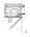
- number 1 indicates as a whole a hinge assembly specifically structured for being used in a household appliance 2 having an horizontally-pivoted front door, such as a stand-alone or built-in, front-loading dishwasher or a stand-alone or built-in, gas or electric oven.
- a built-in front-loading dishwasher 2 which preferably, though not necessarily, comprises:
- the two hinge assemblies 1 are preferably located on opposite sides of front door 4, close to the lower horizontal edge of the door, and are aligned one another so as to allow manual rotation of front door 4 about axis A, between a raised position in which front door 4 is oriented substantially vertically and rests completely against the front wall 3a of casing 3 to close the crockery loading/unloading opening and watertight seal the washing chamber; and a completely lowered position in which front door 4 is oriented substantially horizontally, beneath the crockery loading/unloading opening, so as to give the user free access to the washing chamber via the crockery loading/ unloading opening on front wall 3a.
- dishwasher 2 preferably, though not necessarily, also comprises one or more dish-racks 5 (only one is shown in Figure 1 ) which are housed inside the washing chamber preferably, though not necessarily, one above the other, and each of which is structured for housing the crockery to be washed and is preferably, though not necessarily, fixed to the inner surface of the washing chamber in drawer-like manner so to be manually extractable from the washing chamber through the crockery loading/unloading opening on front wall 3a.
- dish-racks 5 only one is shown in Figure 1
- dish-racks 5 each of which is structured for housing the crockery to be washed and is preferably, though not necessarily, fixed to the inner surface of the washing chamber in drawer-like manner so to be manually extractable from the washing chamber through the crockery loading/unloading opening on front wall 3a.
- each hinge assembly 1 comprises:
- the door-weight balancing device 9 comprises: a straight supporting rod 10 which is coaxial to a longitudinal axis L substantially parallel to coupling plate 6 (i.e. supporting rod 10 lays on a plane substantially perpendicular to the door rotation axis A), and extends in axially sliding manner through a transversally protruding tailpiece 11 which juts out from coupling plates 6; a compression-preloaded helical spring 12 or similar elastically-deformable tubular member which is fitted to supporting rod 10 so as to have a first end 12a rigidly fixed to the distal end 10a of supporting rod 10, and a second end 12b in abutment against the protruding tailpiece 11 of coupling plate 6, so that axial movement of supporting rod 10 varies the length of helical spring 12; and a linking mechanism 13 which connects the proximal end 10b of supporting rod 10 to coupling plate 7, at a given distance from reference axis R of transversal pin 8 (i.e.
- the door-weight balancing device 9 additionally comprises an adjustable spacer element 14 which is interposed between the protruding tailpiece 11 and the second end 12b of helical spring 12, and which is structured so as to allow a manually-operated continuous adjustment, between a lower value and a higher value, of the distance h between the protruding tailpiece 11 and the second end 12b of helical spring 12.
- the adjustable spacer element 14 directly increases or reduces the actual maximum length of helical spring 12 on supporting rod 10 and, therefore, it allows as manually-operated continuous adjustment of the compression preload of helical spring 12 between a lower value and a higher value.
- the linking mechanism 13 preferably comprises a movable guide member 15 which is fixed in sliding manner onto coupling plate 6, approximately between protruding tailpiece 11 and transversal pin 8, so as to be substantially aligned to supporting rod 10 on opposite side of tailpiece 11 with respect to spacer element 14, and so as to be freely movable onto coupling plate 6 towards and backwards the protruding tailpiece 11 in a direction locally substantially parallel to the rod longitudinal axis L.
- the movable guide member 15 is moreover directly faced to, and rigidly connected to, the proximal end 10b of supporting rod 10 so as to move axially the supporting rod 10 with respect to protruding tailpiece 11.
- the linking mechanism 13 also comprises a substantially flat, connecting arm or rod 16 which extends on a plane locally substantially perpendicular to reference axis R, and has a first end 16a directly hinged to coupling plate 7 at a given distance from pin 8, and a second end 16b hinged to guide member 15, so that the whole connecting arm 16 is able to both freely move above coupling plate 6 towards and backwards the protruding tailpiece 11 in a direction locally substantially parallel to the rod longitudinal axis L, and to freely rotate with respect to coupling plate 7 and guide member 15 while remaining on a plane locally substantially perpendicular to reference axis R of transversal pin 8.
- connecting arm or rod 16 connects coupling plate 7 to guide member 15 so to transform the rotating movement of coupling plate 7 about reference axis R, i.e. the rotating movement of front door 4 about door rotation axis A, into an axial reciprocating movement of supporting rod 10 through protruding tailpiece 11.
- guide member 15 preferably, though not necessarily, consists of a substantially flat, transversal rocket arm 17 which extends immediately above coupling plate 6, approximately between protruding tailpiece 11 and transversal pin 8, and which has its intermediate section both rigidly connected to the proximal end 10b of supporting rod 10, and pivotally jointed to connecting arm or rod 16.
- the two opposite ends of rocket arm 17 are finally hinged each to a respective sliding block 18 which, in turn, is fixed in sliding manner to coupling plate 6 so as to be able to freely slide on the body of supporting plate 6 in a direction locally substantially parallel to the longitudinal axis L of supporting rod 10 and helical spring 12, towards and backwards protruding tailpiece 11.
- the adjustable spacer element 14 comprises two substantially wedge-shaped blocks or bodies 20 and 21 which are piled up roughly aligned to the longitudinal axis L of supporting rod 10, and are fitted to supporting rod 10 between the protruding tailpiece 11 and the second end 12b of helical spring 12, so that the wedge-shaped block 20 abuts exclusively against the protruding tailpiece 11, and the wedge-shaped block 21 abuts exclusively against the end 12b of helical spring 12.
- a washer or bushing is preferably, though not necessarily, interposed between the second end 12b of helical spring 12 and the wedge-shaped block 21, i.e. the adjustable spacer element 14.
- the two wedge-shaped blocks 20 and 21 are structured so to be able to slide/move one onto the other along a preferably, though not necessarily, straight travelling direction d having a vectorial component parallel to the longitudinal axis L of supporting rod 10, so that any reciprocal movement of the wedge-shaped blocks 20 and 21 causes a variation of the overall high of the adjustable spacer element 14 parallel to longitudinal axis L and, as a consequence, a variation of the distance h between the protruding tailpiece 11 and the second end 12b of helical spring 12.
- travelling direction d is preferably, though not necessarily, locally parallel to coupling plate 6, and is tilted of an angle a preferably, though not necessarily, ranging between 5° and 85° with respect to the longitudinal axis L of supporting rod 10.
- travelling direction d is preferably, though not necessarily, tilted of an angle a equal to 30° or 45° with respect to the longitudinal axis L of supporting rod 10.
- adjustable spacer element 14 is provided with a manually-oparated adjusting mechanism 22 which is structured so to both prevent any undesired reciprocal movement of the two wedge-shaped blocks 20 and 21, and to selectively move the two wedge-shaped blocks 20 and 21 one with respect to the other along the direction d, so to permit a continuous manually-operated adjustment of the distance h between the protruding tailpiece 11 and the second end 12b of helical spring 12 and, as a consequence, of the actual compression preload of helical spring 12 fitted on supporting rod 10.
- the wedge-shaped block 20 is rigidly fixed to the protruding tailpiece 11; and the wedge-shaped block 21 abuts against helical spring 12, or rather the washer or bushing on the second end 12b of helical spring 12, with a substantially flat upper surface locally perpendicular to the longitudinal axis L of supporting rod 10, so as to allow the second end 12b of helical spring 12 to freely slide on wedge-shaped block 21.
- the manually-operated adjusting mechanism 22 rigidly connects the wedge-shaped block 21 to the coupling plate 6, and it is structured so to selectively move the wedge-shaped block 21 with respect to coupling plate 6, onto the wedge-shaped block 20 along direction d, for alternatively increasing or reducing the overall high of the adjustable spacer element 14 and, as a consequence, continuously adjusting the distance h between the protruding tailpiece 11 and the second end 12b of helical spring 12.
- wedge-shaped block 20 is preferably provided with a central through cavity dimensioned to allow exclusively axial displacements of supporting rod 10
- wedge-shaped block 21 is provided with a central through cavity dimensioned to allow both axial and transversal displacements of supporting rod 10 parallel to coupling plate 6, and rests onto wedge-shaped block 20 on a flat contact surface which lays on a reference plane P locally perpendicular to coupling plate 6 and locally tilted of an angle a preferably, though not necessarily, ranging between 5° and 85° with respect to the longitudinal axis L of supporting rod 10, so that any transversal movement of wedge-shaped block 21 with respect to supporting rod 10 and wedge-shaped block 20 causes an increase or reduction of the distance h between the protruding tailpiece 11 and the flat upper surface of wedge-shaped block 21 against which the second end 12b of helical spring 12 abuts.
- the adjusting mechanism 22 in turn, preferably consists of a connecting screw 22 which is fixed in axially rotating manner to coupling plate 6, beside wedge-shaped block 21, and extends towards wedge-shaped block 21 while remaining locally parallel to travelling direction d up to reach and screw into the body of the wedge-shaped block 21, so that any rotation of the connecting screw 22 causes a sliding of the wedge-shaped block 21 onto the wedge-shaped block 20 along direction d and, as a consequence, causes an increase or reduction of the distance h between the protruding tailpiece 11 and the flat upper surface of the wedge-shaped block 21 against which the second end 12b of helical spring 12 abuts.
- coupling plate 6 is structured for being fixed to the lateral wall 3b of outer casing 3 immediately beside the crockery loading/ unloading opening on front wall 3a, so that the head 22a of connecting screw 22, i.e. the manually-operated adjusting mechanism 22, crops out of front wall 3a beside the crockery loading/unloading opening, and it is easily accessible to the user when front door 4 is not in the raised position.
- the door-weight balancing device 9 therefore allows an on-site, manually-operated adjustment of the compression preload of the helical spring 12 fitted on supporting rod 10.
- door-weight balancing device 9 offers several advantages. First of all, the door-weight balancing device 9 allows the user to manually adjust the compression preload of helical spring 12 in a continuous and extremely precise manner, simply acting exclusively on the manually-operated adjusting mechanism 22, i,e, on the head 22a of connecting screw 22.
- the adjustment speed of the compression preload of helical spring 12 depends solely on the tilt angle ⁇ of the travelling direction d with respect to the longitudinal axis L of supporting rod 10, thus even a few turns of the connecting screw 22 can cause relevant variation of the helical-spring compression preload.
- a tilt angle ⁇ approximately equal to 45° offers the best compromise between speed and adjustment accuracy of the helical-spring compression preload.
- the head 22a of the adjusting screw 22 of the on-site adjustable door-weight balancing device 9 is located on the front wall 3a of casing 3, in a raised position which is easy reachable by the user without removing the household appliance from the niche in the kitchen furniture where it is recessed.
- the adjusting mechanism of the on-site adjustable door-weight balancing device 9 is located in a raised position which is particularly user friendly.
- hinge assembly 1 Last but not least, in hinge assembly 1 the on-site adjustable door-weight balancing device 9 is wholly integrated in coupling plate 6, thus the assembly of hinge assembly 1 on the appliance casing is greatly simplified and cost-effective.
- transversal pin 8 may be replaced by a multilink leverage mechanism which is preferably, though not necessarily, structured to allow a free rotation of coupling plate 7 with respect to coupling plate 6 about a rotation axis locally substantially perpendicular to both coupling plates 6 and 7, and, at the same time, a transversal displacement of coupling plate 7 with respect to coupling plate 6 in a direction locally perpendicular to said rotation axis.
- the door rotation axis A is therefore allowed to space out from front wall 3a of outer casing 3 while front door 4 rotates about axis A.
- the wedge-shaped block 20 abuts against the protruding tailpiece 11 with the possibility to slide above tailpiece 11 in a direction locally parallel to coupling plate 6 and preferably, though not necessarily, roughly perpendicular to the longitudinal axis L of supporting rod 10,
- the wedge-shaped block 21 instead is fitted to supporting rod 10 exclusively in axially sliding manner, and rests onto the wedge-shaped block 20 on a flat contact surface which lays on a reference plane P locally perpendicular to coupling plate 6 and locally tilted of an angle ⁇ preferably, though not necessarily, ranging between 5° and 85° with respect to the longitudinal axis L of supporting rod 10, so that any transversal displacement of wedge-shaped block 20 with respect to supporting rod 10 obliges the wedge-shaped block 21 to slide onto the wedge-shaped block 20 along a travelling direction d having a vectorial component parallel to longitudinal axis L of supporting rod 10, thus causing an increase or reduction of the distance h between the protruding tailpiece 11 and the second end 12b of helical spring 12 and, as a consequence, an increase or reduction of the compression preload of helical spring 12 fitted on supporting rod 10.
- the manually-operated adjusting mechanism 22 in this embodiment it consists of a connecting screw 22 which is fixed in axially rotating manner to coupling plate 6, beside the wedge-shaped block 20, and extends towards wedge-shaped block 20 while remaining locally perpendicular to the longitudinal axis L of supporting rod 10, i.e. locally parallel to the sliding direction of wedge-shaped block on protruding tailpiece 11, up to reach and screw into the body of the wedge-shaped block 20, so that any rotation of connecting screw 22 causes a sliding of the wedge-shaped block 21 onto the wedge-shaped block 20 along the travelling direction d, thus causing an increase or reduction of the distance h between the protruding tailpiece 11 and the second end 12b of helical spring 12.
- one of the two hinge assemblies 1 connecting the front door 4 to the front wall 3a of casing 3 may be replaced by a traditional hinge assembly which is either provided with or lacks a corresponding door-weight balancing device.
Landscapes
- Engineering & Computer Science (AREA)
- Mechanical Engineering (AREA)
- Hinges (AREA)
- Closing And Opening Devices For Wings, And Checks For Wings (AREA)
Priority Applications (5)
| Application Number | Priority Date | Filing Date | Title |
|---|---|---|---|
| EP10014483.1A EP2453091B1 (de) | 2010-11-11 | 2010-11-11 | Scharniereinheit für Haushaltsgeräte mit einer horizontal schwenkbaren Vordertür |
| PL10014483.1T PL2453091T3 (pl) | 2010-11-11 | 2010-11-11 | Zespół zawiasu dla urządzeń gospodarstwa domowego mających przednie drzwi o poziomej osi obrotu |
| PCT/EP2011/066370 WO2012062506A1 (en) | 2010-11-11 | 2011-09-21 | Hinge assembly for household appliances having an horizontally-pivoted front door |
| CN201180052743.8A CN103201446B (zh) | 2010-11-11 | 2011-09-21 | 用于具有水平枢转的前门的家用电器的铰链组件 |
| US13/881,981 US8985717B2 (en) | 2010-11-11 | 2011-09-21 | Hinge assembly for household appliances having an horizontally-pivoted front door |
Applications Claiming Priority (1)
| Application Number | Priority Date | Filing Date | Title |
|---|---|---|---|
| EP10014483.1A EP2453091B1 (de) | 2010-11-11 | 2010-11-11 | Scharniereinheit für Haushaltsgeräte mit einer horizontal schwenkbaren Vordertür |
Publications (2)
| Publication Number | Publication Date |
|---|---|
| EP2453091A1 true EP2453091A1 (de) | 2012-05-16 |
| EP2453091B1 EP2453091B1 (de) | 2016-03-16 |
Family
ID=43821800
Family Applications (1)
| Application Number | Title | Priority Date | Filing Date |
|---|---|---|---|
| EP10014483.1A Active EP2453091B1 (de) | 2010-11-11 | 2010-11-11 | Scharniereinheit für Haushaltsgeräte mit einer horizontal schwenkbaren Vordertür |
Country Status (5)
| Country | Link |
|---|---|
| US (1) | US8985717B2 (de) |
| EP (1) | EP2453091B1 (de) |
| CN (1) | CN103201446B (de) |
| PL (1) | PL2453091T3 (de) |
| WO (1) | WO2012062506A1 (de) |
Cited By (2)
| Publication number | Priority date | Publication date | Assignee | Title |
|---|---|---|---|---|
| ITUB20155424A1 (it) * | 2015-11-10 | 2017-05-10 | C M I Cerniere Mecc Industriali Srl | Dispositivo a cerniera con possibilita di apertura a sfiato |
| CN113391502A (zh) * | 2020-03-11 | 2021-09-14 | 中强光电股份有限公司 | 调整模块及投影机 |
Families Citing this family (18)
| Publication number | Priority date | Publication date | Assignee | Title |
|---|---|---|---|---|
| US9404299B2 (en) * | 2012-05-02 | 2016-08-02 | Bsh Home Appliances Corporation | Home appliance with adjustable hinges |
| ITBO20120244A1 (it) * | 2012-05-04 | 2013-11-05 | Nuova Star Spa | Cerniera per ante o sportelli, di elettrodomestici quali forni, lavastoviglie o simili |
| US9074404B2 (en) * | 2012-05-30 | 2015-07-07 | Bsh Home Applicances Corporation | Household appliance having system for aligning doors and method thereof |
| JP6245945B2 (ja) * | 2012-11-20 | 2017-12-13 | キヤノン株式会社 | 開閉機構及びそれを有する画像形成装置 |
| CN105089402B (zh) * | 2014-05-14 | 2017-03-22 | 佛山市顺德区美的洗涤电器制造有限公司 | 洗碗机 |
| BE1022668B1 (nl) * | 2014-12-29 | 2016-07-05 | Van Parys, Remi Emiel | Verdektliggend scharnier voor een pivoterend raam of pivoterende deur en raam daarmee uitgerust |
| ITUB20152915A1 (it) * | 2015-08-05 | 2017-02-05 | C M I Cerniere Mecc Industriali Srl | Dispositivo a cerniera con lunga traslazione di un pannello frontale |
| CN105054883B (zh) * | 2015-08-19 | 2018-10-23 | 佛山市顺德区美的洗涤电器制造有限公司 | 用于洗碗机的铰链组件及洗碗机 |
| ITUA20161650A1 (it) * | 2016-03-14 | 2017-09-14 | Nuova Star Spa | Cerniera per ante di elettrodomestici. |
| US10655376B2 (en) | 2016-08-10 | 2020-05-19 | Whirlpool Corporation | Dishwasher door with counterbalance assembly |
| CN108487806B (zh) * | 2018-02-02 | 2023-08-15 | 江苏玖星精密科技集团有限公司 | 一种具自动闭合和悬停功能的双支点洗碗机铰链 |
| WO2020058366A1 (en) * | 2018-09-20 | 2020-03-26 | C.M.I. Cerniere Meccaniche Industriali S.R.L. | Damped and compact hinge device |
| DE102019100188A1 (de) * | 2019-01-07 | 2020-07-09 | Grass Gmbh | Vorrichtung zum Bewegen einer Möbelklappe und Möbel |
| CN110313844A (zh) * | 2019-08-21 | 2019-10-11 | 无锡市惠昌烧烤炉科技有限公司 | 烧烤炉阻尼铰链 |
| CN112568844B (zh) * | 2019-09-30 | 2024-05-17 | 青岛海尔洗碗机有限公司 | 一种水槽式洗碗机 |
| IT202000031142A1 (it) * | 2020-12-16 | 2022-06-16 | Nuova Star Spa | Cerniera per sportelli |
| WO2022217423A1 (zh) * | 2021-04-12 | 2022-10-20 | 深圳市金合联供应链技术有限公司 | 一种下翻门缓冲铰链 |
| JP2023047471A (ja) * | 2021-09-27 | 2023-04-06 | 富士フイルムビジネスイノベーション株式会社 | 開閉装置および画像形成装置 |
Citations (4)
| Publication number | Priority date | Publication date | Assignee | Title |
|---|---|---|---|---|
| DE1628803A1 (de) * | 1968-03-08 | 1971-11-25 | Siemens Elektrogeraete Gmbh | Kompensationsvorrichtung fuer die Beschickungstuer einer Geschirrspuelmaschine |
| DE3140039A1 (de) | 1981-10-08 | 1983-04-21 | Bosch-Siemens Hausgeräte GmbH, 7000 Stuttgart | Vorrichtung zum gewichtsausgleich einer klappbaren tuer von haushaltgeraeten |
| EP0565809A1 (de) * | 1992-04-17 | 1993-10-20 | NUOVA STAR S.r.l. | Perfektioniertes Scharnier zum Halten von Türen an einer Tragstruktur |
| EP1602883A2 (de) | 2004-05-31 | 2005-12-07 | NUOVA STAR S.p.A. | Türscharnier |
Family Cites Families (18)
| Publication number | Priority date | Publication date | Assignee | Title |
|---|---|---|---|---|
| US1616471A (en) * | 1925-07-06 | 1927-02-08 | Charles W Peck | Oven-door spring control |
| US1640036A (en) * | 1926-08-30 | 1927-08-23 | John T Hueckel | Oven-door mechanism |
| US3196482A (en) * | 1963-02-21 | 1965-07-27 | Nat Lock Co | Counterbalance hinge assembly |
| US3503380A (en) * | 1968-06-06 | 1970-03-31 | United Filtration Corp | Hinges |
| US3698781A (en) * | 1971-01-27 | 1972-10-17 | Gen Motors Corp | Cabinet door mounting |
| US3749080A (en) * | 1972-03-02 | 1973-07-31 | United Filtration Corp | Oven door hinge |
| US4665892A (en) * | 1985-06-24 | 1987-05-19 | The Stanley Works | Oven door hinge assembly |
| IT1274837B (it) * | 1994-07-15 | 1997-07-25 | Cmi Srl | Sistema di controbilanciamento con registro dell'azione controbilanciante per cerniere, particolarmente indicato per cerniere ad asse di articolazione orizzontale per elettrodomestici. |
| EP0858767B1 (de) * | 1997-02-17 | 2001-11-28 | NUOVA STAR S.p.A. | Vorrichtung zum Anlenken einer Tür, insbesondere einer Geschirrspülmaschinentür, an eine feste Struktur |
| EP1287222B1 (de) * | 2001-02-15 | 2004-04-28 | Gronbach Forschung- und Entwicklungs GmbH & Co. KG | Scharnier für eine herdklappe |
| EP2116167B1 (de) * | 2008-05-08 | 2011-09-28 | Electrolux Home Products Corporation N.V. | Geschirrspüler mit Dämpfmittel zum Dämpfen beim Schließen der Türe |
| DE102008050885A1 (de) * | 2008-10-09 | 2010-04-22 | Roto Frank Ag | Entlastungsanordnung eines Fensters, einer Tür oder dergleichen |
| CN201288466Y (zh) * | 2008-10-28 | 2009-08-12 | 童伟义 | 下拉式翻板门的弹簧铰链 |
| US8201304B2 (en) * | 2009-02-25 | 2012-06-19 | General Electric Company | Compliant door hinge |
| IT1393614B1 (it) * | 2009-04-08 | 2012-05-08 | Nuova Star Spa | Cerniera per ante o sportelli |
| CN101619640A (zh) * | 2009-08-17 | 2010-01-06 | 常州市威普电子科技有限公司 | 用于家用电器上的铰链 |
| US20110146654A1 (en) * | 2009-12-21 | 2011-06-23 | Whirlpool Corporation | Limited load hinge for freestanding appliance |
| KR101960820B1 (ko) * | 2012-10-08 | 2019-03-21 | 삼성전자주식회사 | 오븐 |
-
2010
- 2010-11-11 PL PL10014483.1T patent/PL2453091T3/pl unknown
- 2010-11-11 EP EP10014483.1A patent/EP2453091B1/de active Active
-
2011
- 2011-09-21 US US13/881,981 patent/US8985717B2/en active Active
- 2011-09-21 CN CN201180052743.8A patent/CN103201446B/zh not_active Expired - Fee Related
- 2011-09-21 WO PCT/EP2011/066370 patent/WO2012062506A1/en active Application Filing
Patent Citations (4)
| Publication number | Priority date | Publication date | Assignee | Title |
|---|---|---|---|---|
| DE1628803A1 (de) * | 1968-03-08 | 1971-11-25 | Siemens Elektrogeraete Gmbh | Kompensationsvorrichtung fuer die Beschickungstuer einer Geschirrspuelmaschine |
| DE3140039A1 (de) | 1981-10-08 | 1983-04-21 | Bosch-Siemens Hausgeräte GmbH, 7000 Stuttgart | Vorrichtung zum gewichtsausgleich einer klappbaren tuer von haushaltgeraeten |
| EP0565809A1 (de) * | 1992-04-17 | 1993-10-20 | NUOVA STAR S.r.l. | Perfektioniertes Scharnier zum Halten von Türen an einer Tragstruktur |
| EP1602883A2 (de) | 2004-05-31 | 2005-12-07 | NUOVA STAR S.p.A. | Türscharnier |
Cited By (4)
| Publication number | Priority date | Publication date | Assignee | Title |
|---|---|---|---|---|
| ITUB20155424A1 (it) * | 2015-11-10 | 2017-05-10 | C M I Cerniere Mecc Industriali Srl | Dispositivo a cerniera con possibilita di apertura a sfiato |
| WO2017081013A1 (en) * | 2015-11-10 | 2017-05-18 | C.M.I. Cerniere Meccaniche Industriali S.R.L. | Hinge device with the possibility of breather opening |
| US10858870B2 (en) | 2015-11-10 | 2020-12-08 | C.M.I. Cerniere Meccaniche Industriali S.R.L. | Hinge device with the possibility of ajar or breather opening |
| CN113391502A (zh) * | 2020-03-11 | 2021-09-14 | 中强光电股份有限公司 | 调整模块及投影机 |
Also Published As
| Publication number | Publication date |
|---|---|
| US20130214663A1 (en) | 2013-08-22 |
| EP2453091B1 (de) | 2016-03-16 |
| CN103201446B (zh) | 2016-01-06 |
| PL2453091T3 (pl) | 2016-09-30 |
| US8985717B2 (en) | 2015-03-24 |
| WO2012062506A1 (en) | 2012-05-18 |
| CN103201446A (zh) | 2013-07-10 |
Similar Documents
| Publication | Publication Date | Title |
|---|---|---|
| EP2453091B1 (de) | Scharniereinheit für Haushaltsgeräte mit einer horizontal schwenkbaren Vordertür | |
| EP2407723B1 (de) | Gleitscharnier für Haushaltsgerät | |
| JP6295246B2 (ja) | スライドドア取付具 | |
| US7243396B2 (en) | Door hinge | |
| KR101603462B1 (ko) | 가구용 힌지 | |
| EP1066789B1 (de) | Hebevorrichtung für den unteren Korb einer Geschirrspülmaschine | |
| EP2556782B1 (de) | Geschirrspüler | |
| US11008793B2 (en) | Flap holder for a furniture flap | |
| US20150345203A1 (en) | Hinge for doors of electrical household appliances | |
| EP2519680B1 (de) | Haushaltsgerät | |
| CA2746104C (en) | A household appliance comprising a sliding decorative panel on its door | |
| KR20160032420A (ko) | 이동 가능한 핸들을 갖는 가전제품 | |
| KR20160133168A (ko) | 이동 가능한 핸들을 갖는 가전제품 | |
| EP2482703A1 (de) | Einbaugeschirrspüler mit an der tür befindlicher dekorationstafel | |
| US11603693B2 (en) | Furniture hinge for upward-opening cabinet doors | |
| EP3621507A1 (de) | Scharnier für haushaltsgerät | |
| CN108049123B (zh) | 底脚结构和家用电器 | |
| EP2128369A2 (de) | Scharnier für Flügel oder Türen | |
| EP2699724B1 (de) | Haushaltsgerät | |
| KR102114079B1 (ko) | 식기세척기 | |
| EP1960217B1 (de) | Haushaltsgerät | |
| CN219691343U (zh) | 一种用于家用电器的门阻尼结构及家用电器 | |
| CN108351156B (zh) | 家用器具设备和用于运行家用器具设备的方法 | |
| CN211549258U (zh) | 电动铰链 | |
| EP1443846B1 (de) | Gegengewicht-scharnier-vorrichtung mit vertikalbewegung für eine tür |
Legal Events
| Date | Code | Title | Description |
|---|---|---|---|
| PUAI | Public reference made under article 153(3) epc to a published international application that has entered the european phase |
Free format text: ORIGINAL CODE: 0009012 |
|
| AK | Designated contracting states |
Kind code of ref document: A1 Designated state(s): AL AT BE BG CH CY CZ DE DK EE ES FI FR GB GR HR HU IE IS IT LI LT LU LV MC MK MT NL NO PL PT RO RS SE SI SK SM TR |
|
| AX | Request for extension of the european patent |
Extension state: BA ME |
|
| 17P | Request for examination filed |
Effective date: 20121116 |
|
| 17Q | First examination report despatched |
Effective date: 20130118 |
|
| GRAP | Despatch of communication of intention to grant a patent |
Free format text: ORIGINAL CODE: EPIDOSNIGR1 |
|
| INTG | Intention to grant announced |
Effective date: 20151109 |
|
| GRAS | Grant fee paid |
Free format text: ORIGINAL CODE: EPIDOSNIGR3 |
|
| GRAA | (expected) grant |
Free format text: ORIGINAL CODE: 0009210 |
|
| AK | Designated contracting states |
Kind code of ref document: B1 Designated state(s): AL AT BE BG CH CY CZ DE DK EE ES FI FR GB GR HR HU IE IS IT LI LT LU LV MC MK MT NL NO PL PT RO RS SE SI SK SM TR |
|
| REG | Reference to a national code |
Ref country code: GB Ref legal event code: FG4D |
|
| REG | Reference to a national code |
Ref country code: CH Ref legal event code: EP |
|
| REG | Reference to a national code |
Ref country code: IE Ref legal event code: FG4D |
|
| REG | Reference to a national code |
Ref country code: AT Ref legal event code: REF Ref document number: 781435 Country of ref document: AT Kind code of ref document: T Effective date: 20160415 |
|
| REG | Reference to a national code |
Ref country code: DE Ref legal event code: R096 Ref document number: 602010031148 Country of ref document: DE |
|
| REG | Reference to a national code |
Ref country code: NL Ref legal event code: MP Effective date: 20160316 |
|
| REG | Reference to a national code |
Ref country code: LT Ref legal event code: MG4D |
|
| PG25 | Lapsed in a contracting state [announced via postgrant information from national office to epo] |
Ref country code: FI Free format text: LAPSE BECAUSE OF FAILURE TO SUBMIT A TRANSLATION OF THE DESCRIPTION OR TO PAY THE FEE WITHIN THE PRESCRIBED TIME-LIMIT Effective date: 20160316 Ref country code: NO Free format text: LAPSE BECAUSE OF FAILURE TO SUBMIT A TRANSLATION OF THE DESCRIPTION OR TO PAY THE FEE WITHIN THE PRESCRIBED TIME-LIMIT Effective date: 20160616 Ref country code: GR Free format text: LAPSE BECAUSE OF FAILURE TO SUBMIT A TRANSLATION OF THE DESCRIPTION OR TO PAY THE FEE WITHIN THE PRESCRIBED TIME-LIMIT Effective date: 20160617 Ref country code: HR Free format text: LAPSE BECAUSE OF FAILURE TO SUBMIT A TRANSLATION OF THE DESCRIPTION OR TO PAY THE FEE WITHIN THE PRESCRIBED TIME-LIMIT Effective date: 20160316 |
|
| REG | Reference to a national code |
Ref country code: AT Ref legal event code: MK05 Ref document number: 781435 Country of ref document: AT Kind code of ref document: T Effective date: 20160316 |
|
| PG25 | Lapsed in a contracting state [announced via postgrant information from national office to epo] |
Ref country code: LT Free format text: LAPSE BECAUSE OF FAILURE TO SUBMIT A TRANSLATION OF THE DESCRIPTION OR TO PAY THE FEE WITHIN THE PRESCRIBED TIME-LIMIT Effective date: 20160316 Ref country code: SE Free format text: LAPSE BECAUSE OF FAILURE TO SUBMIT A TRANSLATION OF THE DESCRIPTION OR TO PAY THE FEE WITHIN THE PRESCRIBED TIME-LIMIT Effective date: 20160316 Ref country code: NL Free format text: LAPSE BECAUSE OF FAILURE TO SUBMIT A TRANSLATION OF THE DESCRIPTION OR TO PAY THE FEE WITHIN THE PRESCRIBED TIME-LIMIT Effective date: 20160316 Ref country code: LV Free format text: LAPSE BECAUSE OF FAILURE TO SUBMIT A TRANSLATION OF THE DESCRIPTION OR TO PAY THE FEE WITHIN THE PRESCRIBED TIME-LIMIT Effective date: 20160316 Ref country code: RS Free format text: LAPSE BECAUSE OF FAILURE TO SUBMIT A TRANSLATION OF THE DESCRIPTION OR TO PAY THE FEE WITHIN THE PRESCRIBED TIME-LIMIT Effective date: 20160316 |
|
| PG25 | Lapsed in a contracting state [announced via postgrant information from national office to epo] |
Ref country code: EE Free format text: LAPSE BECAUSE OF FAILURE TO SUBMIT A TRANSLATION OF THE DESCRIPTION OR TO PAY THE FEE WITHIN THE PRESCRIBED TIME-LIMIT Effective date: 20160316 Ref country code: IS Free format text: LAPSE BECAUSE OF FAILURE TO SUBMIT A TRANSLATION OF THE DESCRIPTION OR TO PAY THE FEE WITHIN THE PRESCRIBED TIME-LIMIT Effective date: 20160716 |
|
| PG25 | Lapsed in a contracting state [announced via postgrant information from national office to epo] |
Ref country code: SM Free format text: LAPSE BECAUSE OF FAILURE TO SUBMIT A TRANSLATION OF THE DESCRIPTION OR TO PAY THE FEE WITHIN THE PRESCRIBED TIME-LIMIT Effective date: 20160316 Ref country code: SK Free format text: LAPSE BECAUSE OF FAILURE TO SUBMIT A TRANSLATION OF THE DESCRIPTION OR TO PAY THE FEE WITHIN THE PRESCRIBED TIME-LIMIT Effective date: 20160316 Ref country code: CZ Free format text: LAPSE BECAUSE OF FAILURE TO SUBMIT A TRANSLATION OF THE DESCRIPTION OR TO PAY THE FEE WITHIN THE PRESCRIBED TIME-LIMIT Effective date: 20160316 Ref country code: PT Free format text: LAPSE BECAUSE OF FAILURE TO SUBMIT A TRANSLATION OF THE DESCRIPTION OR TO PAY THE FEE WITHIN THE PRESCRIBED TIME-LIMIT Effective date: 20160718 Ref country code: AT Free format text: LAPSE BECAUSE OF FAILURE TO SUBMIT A TRANSLATION OF THE DESCRIPTION OR TO PAY THE FEE WITHIN THE PRESCRIBED TIME-LIMIT Effective date: 20160316 Ref country code: ES Free format text: LAPSE BECAUSE OF FAILURE TO SUBMIT A TRANSLATION OF THE DESCRIPTION OR TO PAY THE FEE WITHIN THE PRESCRIBED TIME-LIMIT Effective date: 20160316 Ref country code: RO Free format text: LAPSE BECAUSE OF FAILURE TO SUBMIT A TRANSLATION OF THE DESCRIPTION OR TO PAY THE FEE WITHIN THE PRESCRIBED TIME-LIMIT Effective date: 20160316 |
|
| REG | Reference to a national code |
Ref country code: DE Ref legal event code: R097 Ref document number: 602010031148 Country of ref document: DE |
|
| PG25 | Lapsed in a contracting state [announced via postgrant information from national office to epo] |
Ref country code: BE Free format text: LAPSE BECAUSE OF FAILURE TO SUBMIT A TRANSLATION OF THE DESCRIPTION OR TO PAY THE FEE WITHIN THE PRESCRIBED TIME-LIMIT Effective date: 20160316 |
|
| PLBE | No opposition filed within time limit |
Free format text: ORIGINAL CODE: 0009261 |
|
| STAA | Information on the status of an ep patent application or granted ep patent |
Free format text: STATUS: NO OPPOSITION FILED WITHIN TIME LIMIT |
|
| PG25 | Lapsed in a contracting state [announced via postgrant information from national office to epo] |
Ref country code: DK Free format text: LAPSE BECAUSE OF FAILURE TO SUBMIT A TRANSLATION OF THE DESCRIPTION OR TO PAY THE FEE WITHIN THE PRESCRIBED TIME-LIMIT Effective date: 20160316 |
|
| 26N | No opposition filed |
Effective date: 20161219 |
|
| PG25 | Lapsed in a contracting state [announced via postgrant information from national office to epo] |
Ref country code: BG Free format text: LAPSE BECAUSE OF FAILURE TO SUBMIT A TRANSLATION OF THE DESCRIPTION OR TO PAY THE FEE WITHIN THE PRESCRIBED TIME-LIMIT Effective date: 20160616 |
|
| PG25 | Lapsed in a contracting state [announced via postgrant information from national office to epo] |
Ref country code: SI Free format text: LAPSE BECAUSE OF FAILURE TO SUBMIT A TRANSLATION OF THE DESCRIPTION OR TO PAY THE FEE WITHIN THE PRESCRIBED TIME-LIMIT Effective date: 20160316 |
|
| GBPC | Gb: european patent ceased through non-payment of renewal fee |
Effective date: 20161111 |
|
| REG | Reference to a national code |
Ref country code: IE Ref legal event code: MM4A |
|
| REG | Reference to a national code |
Ref country code: FR Ref legal event code: ST Effective date: 20170731 |
|
| PG25 | Lapsed in a contracting state [announced via postgrant information from national office to epo] |
Ref country code: LU Free format text: LAPSE BECAUSE OF NON-PAYMENT OF DUE FEES Effective date: 20161130 |
|
| PG25 | Lapsed in a contracting state [announced via postgrant information from national office to epo] |
Ref country code: FR Free format text: LAPSE BECAUSE OF NON-PAYMENT OF DUE FEES Effective date: 20161130 |
|
| PG25 | Lapsed in a contracting state [announced via postgrant information from national office to epo] |
Ref country code: GB Free format text: LAPSE BECAUSE OF NON-PAYMENT OF DUE FEES Effective date: 20161111 Ref country code: IE Free format text: LAPSE BECAUSE OF NON-PAYMENT OF DUE FEES Effective date: 20161111 |
|
| PG25 | Lapsed in a contracting state [announced via postgrant information from national office to epo] |
Ref country code: CY Free format text: LAPSE BECAUSE OF FAILURE TO SUBMIT A TRANSLATION OF THE DESCRIPTION OR TO PAY THE FEE WITHIN THE PRESCRIBED TIME-LIMIT Effective date: 20160316 Ref country code: HU Free format text: LAPSE BECAUSE OF FAILURE TO SUBMIT A TRANSLATION OF THE DESCRIPTION OR TO PAY THE FEE WITHIN THE PRESCRIBED TIME-LIMIT; INVALID AB INITIO Effective date: 20101111 |
|
| PG25 | Lapsed in a contracting state [announced via postgrant information from national office to epo] |
Ref country code: MC Free format text: LAPSE BECAUSE OF FAILURE TO SUBMIT A TRANSLATION OF THE DESCRIPTION OR TO PAY THE FEE WITHIN THE PRESCRIBED TIME-LIMIT Effective date: 20160316 Ref country code: MK Free format text: LAPSE BECAUSE OF FAILURE TO SUBMIT A TRANSLATION OF THE DESCRIPTION OR TO PAY THE FEE WITHIN THE PRESCRIBED TIME-LIMIT Effective date: 20160316 |
|
| PG25 | Lapsed in a contracting state [announced via postgrant information from national office to epo] |
Ref country code: MT Free format text: LAPSE BECAUSE OF NON-PAYMENT OF DUE FEES Effective date: 20161111 |
|
| PG25 | Lapsed in a contracting state [announced via postgrant information from national office to epo] |
Ref country code: AL Free format text: LAPSE BECAUSE OF FAILURE TO SUBMIT A TRANSLATION OF THE DESCRIPTION OR TO PAY THE FEE WITHIN THE PRESCRIBED TIME-LIMIT Effective date: 20160316 |
|
| PGFP | Annual fee paid to national office [announced via postgrant information from national office to epo] |
Ref country code: TR Payment date: 20201109 Year of fee payment: 11 |
|
| PGFP | Annual fee paid to national office [announced via postgrant information from national office to epo] |
Ref country code: CH Payment date: 20201118 Year of fee payment: 11 |
|
| REG | Reference to a national code |
Ref country code: CH Ref legal event code: PL |
|
| PGFP | Annual fee paid to national office [announced via postgrant information from national office to epo] |
Ref country code: IT Payment date: 20221124 Year of fee payment: 13 Ref country code: DE Payment date: 20221123 Year of fee payment: 13 |
|
| PGFP | Annual fee paid to national office [announced via postgrant information from national office to epo] |
Ref country code: PL Payment date: 20221108 Year of fee payment: 13 |
|
| PG25 | Lapsed in a contracting state [announced via postgrant information from national office to epo] |
Ref country code: LI Free format text: LAPSE BECAUSE OF NON-PAYMENT OF DUE FEES Effective date: 20220630 Ref country code: CH Free format text: LAPSE BECAUSE OF NON-PAYMENT OF DUE FEES Effective date: 20220630 |
|
| P01 | Opt-out of the competence of the unified patent court (upc) registered |
Effective date: 20230625 |