EP2452145B1 - Échangeur de chaleur - Google Patents
Échangeur de chaleur Download PDFInfo
- Publication number
- EP2452145B1 EP2452145B1 EP10728682.5A EP10728682A EP2452145B1 EP 2452145 B1 EP2452145 B1 EP 2452145B1 EP 10728682 A EP10728682 A EP 10728682A EP 2452145 B1 EP2452145 B1 EP 2452145B1
- Authority
- EP
- European Patent Office
- Prior art keywords
- heat exchange
- section
- flow paths
- exchange device
- sections
- Prior art date
- Legal status (The legal status is an assumption and is not a legal conclusion. Google has not performed a legal analysis and makes no representation as to the accuracy of the status listed.)
- Active
Links
- 238000004519 manufacturing process Methods 0.000 claims description 5
- 238000002485 combustion reaction Methods 0.000 claims description 4
- 239000012530 fluid Substances 0.000 claims description 3
- 239000007789 gas Substances 0.000 description 10
- 239000002826 coolant Substances 0.000 description 8
- 238000001816 cooling Methods 0.000 description 4
- 238000010276 construction Methods 0.000 description 2
- 238000002309 gasification Methods 0.000 description 2
- 239000012528 membrane Substances 0.000 description 2
- 238000000034 method Methods 0.000 description 2
- XLYOFNOQVPJJNP-UHFFFAOYSA-N water Substances O XLYOFNOQVPJJNP-UHFFFAOYSA-N 0.000 description 2
- 238000004140 cleaning Methods 0.000 description 1
- 238000009826 distribution Methods 0.000 description 1
- 230000017525 heat dissipation Effects 0.000 description 1
- 230000000149 penetrating effect Effects 0.000 description 1
- 238000000197 pyrolysis Methods 0.000 description 1
- 239000004071 soot Substances 0.000 description 1
- 238000003466 welding Methods 0.000 description 1
Images


Classifications
-
- F—MECHANICAL ENGINEERING; LIGHTING; HEATING; WEAPONS; BLASTING
- F28—HEAT EXCHANGE IN GENERAL
- F28D—HEAT-EXCHANGE APPARATUS, NOT PROVIDED FOR IN ANOTHER SUBCLASS, IN WHICH THE HEAT-EXCHANGE MEDIA DO NOT COME INTO DIRECT CONTACT
- F28D7/00—Heat-exchange apparatus having stationary tubular conduit assemblies for both heat-exchange media, the media being in contact with different sides of a conduit wall
- F28D7/0041—Heat-exchange apparatus having stationary tubular conduit assemblies for both heat-exchange media, the media being in contact with different sides of a conduit wall the conduits for only one medium being tubes having parts touching each other or tubes assembled in panel form
-
- F—MECHANICAL ENGINEERING; LIGHTING; HEATING; WEAPONS; BLASTING
- F28—HEAT EXCHANGE IN GENERAL
- F28D—HEAT-EXCHANGE APPARATUS, NOT PROVIDED FOR IN ANOTHER SUBCLASS, IN WHICH THE HEAT-EXCHANGE MEDIA DO NOT COME INTO DIRECT CONTACT
- F28D7/00—Heat-exchange apparatus having stationary tubular conduit assemblies for both heat-exchange media, the media being in contact with different sides of a conduit wall
- F28D7/0008—Heat-exchange apparatus having stationary tubular conduit assemblies for both heat-exchange media, the media being in contact with different sides of a conduit wall the conduits for one medium being in heat conductive contact with the conduits for the other medium
-
- F—MECHANICAL ENGINEERING; LIGHTING; HEATING; WEAPONS; BLASTING
- F28—HEAT EXCHANGE IN GENERAL
- F28D—HEAT-EXCHANGE APPARATUS, NOT PROVIDED FOR IN ANOTHER SUBCLASS, IN WHICH THE HEAT-EXCHANGE MEDIA DO NOT COME INTO DIRECT CONTACT
- F28D7/00—Heat-exchange apparatus having stationary tubular conduit assemblies for both heat-exchange media, the media being in contact with different sides of a conduit wall
- F28D7/16—Heat-exchange apparatus having stationary tubular conduit assemblies for both heat-exchange media, the media being in contact with different sides of a conduit wall the conduits being arranged in parallel spaced relation
- F28D7/163—Heat-exchange apparatus having stationary tubular conduit assemblies for both heat-exchange media, the media being in contact with different sides of a conduit wall the conduits being arranged in parallel spaced relation with conduit assemblies having a particular shape, e.g. square or annular; with assemblies of conduits having different geometrical features; with multiple groups of conduits connected in series or parallel and arranged inside common casing
- F28D7/1669—Heat-exchange apparatus having stationary tubular conduit assemblies for both heat-exchange media, the media being in contact with different sides of a conduit wall the conduits being arranged in parallel spaced relation with conduit assemblies having a particular shape, e.g. square or annular; with assemblies of conduits having different geometrical features; with multiple groups of conduits connected in series or parallel and arranged inside common casing the conduit assemblies having an annular shape; the conduits being assembled around a central distribution tube
-
- F—MECHANICAL ENGINEERING; LIGHTING; HEATING; WEAPONS; BLASTING
- F28—HEAT EXCHANGE IN GENERAL
- F28F—DETAILS OF HEAT-EXCHANGE AND HEAT-TRANSFER APPARATUS, OF GENERAL APPLICATION
- F28F9/00—Casings; Header boxes; Auxiliary supports for elements; Auxiliary members within casings
- F28F9/007—Auxiliary supports for elements
- F28F9/013—Auxiliary supports for elements for tubes or tube-assemblies
- F28F9/0132—Auxiliary supports for elements for tubes or tube-assemblies formed by slats, tie-rods, articulated or expandable rods
-
- F—MECHANICAL ENGINEERING; LIGHTING; HEATING; WEAPONS; BLASTING
- F28—HEAT EXCHANGE IN GENERAL
- F28F—DETAILS OF HEAT-EXCHANGE AND HEAT-TRANSFER APPARATUS, OF GENERAL APPLICATION
- F28F9/00—Casings; Header boxes; Auxiliary supports for elements; Auxiliary members within casings
- F28F9/02—Header boxes; End plates
- F28F9/026—Header boxes; End plates with static flow control means, e.g. with means for uniformly distributing heat exchange media into conduits
- F28F9/027—Header boxes; End plates with static flow control means, e.g. with means for uniformly distributing heat exchange media into conduits in the form of distribution pipes
- F28F9/0275—Header boxes; End plates with static flow control means, e.g. with means for uniformly distributing heat exchange media into conduits in the form of distribution pipes with multiple branch pipes
-
- F—MECHANICAL ENGINEERING; LIGHTING; HEATING; WEAPONS; BLASTING
- F28—HEAT EXCHANGE IN GENERAL
- F28F—DETAILS OF HEAT-EXCHANGE AND HEAT-TRANSFER APPARATUS, OF GENERAL APPLICATION
- F28F2265/00—Safety or protection arrangements; Arrangements for preventing malfunction
- F28F2265/26—Safety or protection arrangements; Arrangements for preventing malfunction for allowing differential expansion between elements
Definitions
- the present invention relates to a heat exchange device for cooling a gas, comprising a channel and one or more heat exchange surfaces disposed in the channel, supported by a support structure.
- the present invention relates, in particular, to a heat exchange device according to the preamble of claim 1 as disclosed in US 3,433,298 .
- Such heat exchangers are for example used in gasification processes for the production of synthetic gas, or syngas.
- carbonaceous feedstock is partially oxidised in a reactor.
- Syngas leaving the reactor typically has a temperature of 1300-1600 °C.
- the hot syngas is quenched to temperatures between 100-700 °C and is then transported to a coiled heat exchanger, generally comprising a number of parallel coiled tubes.
- Support structures are used to support the heat exchange surfaces within the channel formed by the channel wall. Differences in thermal expansion of the various parts complicate possible support constructions. Sliding bearings can be used, allowing some degree of freedom of movement, but such bearings are difficult to realize and less reliable under the circumstances in such reactors.
- US 5,482,110 discloses a heat exchanger for cooling syngas from a partial combustion reactor comprising nested heat exchange surfaces carried by a support. Such a support structure may induce high local stress peaks.
- the object of the invention is achieved by a heat exchange device according to claim 1.
- the heat exchange surfaces can rest on the support structure, or the heat exchange surfaces can hang down from the support structure.
- the one or more heat exchange surfaces can be connected to the support structure, e.g., by welding joints.
- the support structure can be joined to the channel wall, or to a load bearing structure within the channel wall.
- the device can for instance have a number of nested heat exchange surfaces of a closed geometry, e.g., of a cylindrical geometry, as is disclosed in US 5,482,110 .
- the heat exchange surfaces can be coaxially arranged or nested within the channel wall, which will typically be cylindrical.
- the support structure can support a series of two or more bundles of nested heat exchange surfaces.
- the fluid heat exchange medium is water, although any other type of aqueous or non-aqueous coolant can be used if so desired.
- the support structure can comprise a plurality of embedded parallel inner channels each being in open connection with one of the flow paths in the heat exchange surfaces.
- the inner channels are preferably evenly distributed and equidistantly arranged.
- the inner channels may meander through the arm parts of the support structure. Since meandering inner channels are difficult to manufacture, the arm parts may be built of a number of sections each embedding parallel and equidistant inner channels making a single turn, e.g., of about 90 degrees.
- each arm of the support structure may comprise:
- the heat distribution with this configuration is such that differences in thermal expansion of the connected parts do not result in high mechanical stress loads.
- the arms of the support structure can for example be formed as blocks or plates embedding inner channels operatively connected to the tubular parts.
- one or more of the arms of the support structure can wholly or partly be composed of tubular parts, optionally in combination with blocks or plates embedding inner channels operatively connected to the tubular parts.
- the height of the support structure can be increased. This way, the support structure can be made stronger without increasing the thickness of the support structure arms, which could result in undesirable high wall temperatures of the support structure.
- the thickness of the arms of the support structure should be sufficient to give the support structure the required carrying capacity. Generally, a wall thickness of 5-20 mm at both sides of an inner channel balances sufficient strength with good heat dissipation capacity.
- the heat exchange surfaces are cleaned by rapping devices which can regularly be actuated during operation of the reactor.
- rapping devices which can regularly be actuated during operation of the reactor.
- pneumatically operated rapping devices the individual heat exchange surfaces are accelerated to such an extent, that soot deposits and fouling are effectively removed.
- Cleaning by rapping can be done particularly effectively if all tubes of one heat exchange surface unit are rigidly connected to one constructive gastight unit, e.g., by constructing the heat exchange surfaces as a tube-stay-tube or fin-tube construction.
- the heat exchange surfaces can be assembled as a plurality of nested heat exchange surfaces of a closed geometry whereby the inner heat exchange surface has a greater constructive height than the adjacent outer heat exchange surface so that each heat exchange surface can be rapped from the exterior without the need for penetrating any other heat exchange surfaces.
- one or more deflectors arranged within the inner heat exchange surface of the nested set may be used to guide the hot gas flow towards the heat exchange surfaces, in order to cool all of the gas evenly.
- the heat exchange device according to the present invention can for example be a section of a partial combustion reactor for the production of synthetic gas.
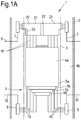
- Figure 1A shows in longitudinal cross section a heat exchange section 1 of a partial combustion reactor for the production of syngas.
- the section 1 comprises a cylindrical outer wall 2.
- the outer wall 2 encloses a concentrically arranged inner channel wall or membrane 3 built of parallel tubular pipe lines, schematically represented in the drawing by centrelines.
- the tubular pipe lines of the inner channel wall 3 are welded together - e.g., directly or via fins - to form a gastight wall.
- a cooling medium, such as water flows through the pipe lines of the channel wall 3.
- the inner channel wall 3 encloses a set of four schematically represented nested coaxial heat exchange surfaces 5a, 5b, 5c, and 5d. In practice, two or more may be used-for example heat exchange surfaces 5a and 5b. Like the inner channel wall 3, the heat exchange surfaces 5a - d are built of parallel tubular lines. Optionally, the tubular lines of the heat exchange surfaces 5a - d can be helically wound.
- the inner channel wall or membrane 3 defines a central channel 4a for hot gas flowing downwards along the heat exchange surfaces 5a - d towards a discharge.
- the cooled gas can enter the annular space 4b between the inner channel wall 3 and the outer wall 2. Coolant flowing through the pipe lines of inner channel wall 3 isolates the cool gas in the annular channel 4b from the hot gas in the central channel 4a.
- each inner heat exchange surface 5b - d extends past the lower end 6 of the adjacent outer heat exchange surface 5a - c, respectively. This way, each individual heat exchange surface 5a - d can be cleaned individually by using rapper devices (not shown).
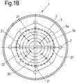
- coolant discharge lines 7 are provided between the inner channel wall 3 and the outer channel wall 2, as schematically shown in Figure 1B .
- the discharge end 8 of the lines 7 passes the outer wall 2 to form a connection to a coolant discharge.
- the discharge lines 7 and at a distance below these discharge lines 7, are four supply lines 9.
- the upper ends 10 of the supply lines 9 pass through the outer wall 2 to form a connection to a coolant supply.
- Coolant feed lines 16 connect the supply lines 9 to the heat exchange surfaces 5a - d.
- the arrangement of the supply lines and discharge lines can also be reversed depending on the cooling media.
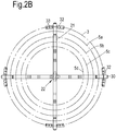
- a horizontal support cross 20 has four arms 21 extending from a central crossing 22 to a corresponding coolant discharge line 7.
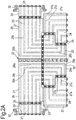
- the support cross 20 is shown in more detail in Figures 2A and 2B .
- Parallel inner channels 23 run through the arms 21, each inner channel 23 being in open connection with the flow paths in the heat exchange surfaces 5a - d.
- the inner channels 23 are evenly distributed over the corresponding arm 21.
- the top side of each of the heat exchange surfaces 5a - d comprises two vertical line sections 19, axially symmetrically arranged, extending vertically towards the support cross 20, where they are connected to the embedded inner channels 23, as shown in Figure 1A .
- Each arm 21 comprises a first and a second lower arm part 24, 25 respectively, and an upper arm part 26.
- first lower arm part 24 equidistantly arranged parallel flow paths 27 have a first part 27a extending upwardly to a first corner 27b and a second section 27c extending in the direction of the crossing section 22.
- the flow paths 28 in the second lower arm parts 25 have a first horizontal section 28a in line with the respective flow paths 27c in the first part 24 extending to a second corner 28b, and a second section 28c extending upwardly from the second corner 28b.
- the flow paths 29 in the upper arm parts 26 have a first vertical section 29a in line with the respective flow paths 28 in the second lower arm part 25 extending upwardly to a third corner 29b, and a second section 29c extending from the third corner 29b away from the crossing section 22.
- extension parts 30 are rectangular parts with equidistantly arranged inner channels 31 embedded in line with the horizontal channel sections 28c in the upper arm parts 26.
- Blocks 32 are attached to both sides of the extension part 30.
- the blocks 32 are in line with the inner channel wall 3 and have the same curvature.
- the blocks 32 are provided with inner channels 33 which are operatively connected to the tubular lines 4 in the channel wall 3.
- FIG. 3 shows in side view an alternative support cross 40 for a heat exchanger according to the present invention.
- the support cross comprises four arms 41 of equal length forming a cross with a centre part 42.
- Each arm 41 is made of four sections: a lower main section 43, a lower central section 44, an upper centre section 45 and an upper main section 46.
- Inner channels 47a and 47b are embedded in the lower main section 43 with a vertically extending channel section 47a at the lower side of the lower main section 43 and a horizontally extending channel section 47b, extending to a lateral side of the lower main section 43. Three of the channel sections 47b extend towards the adjacent lower central section 44.
- the upper one of channels sections 47b has its upper longitudinal half formed as a pipeline in a rectangular cut-out 48 in the lower main section 43.
- Inner channels 49a and 49b are embedded in the lower central section 44, having horizontal channel sections 49a connected at one end to the channel sections 47b in the lower main section 43, and to vertical channel sections 49b at their other end.
- the lower central section 44 is mirrored by the upper central section 45, which embeds inner channels 50a and 50b, with vertical sections 50a in line with the vertical inner channels sections 49b in lower central section 44.
- Horizontal channels sections 50b lead from the vertical channel sections 50a to the side of the upper central section 45 opposite the centre 22.
- the upper main section 46 is made of three horizontal parallel pipe lines 51 operatively connected to the horizontal channel sections 50b in upper central section 45.
- the pipe lines 51 lead to an extension block 52 with three inner channels 53 connected to the pipe lines 51.
- FIG 4 shows a heat exchange device 60 similar to the heat exchange device of Figure 1A and 1B .
- the same reference numbers are used for parts that are the same in both embodiments.
- the heat exchange device in Figure 4 comprises two bundles 61, 62 in line above one another of four nested heat exchange surfaces 61a - d, 62a - d. Because of the double weight that has to be supported a support cross 63 is used which is thicker than the support cross 20 in Figure 1A .
Landscapes
- Engineering & Computer Science (AREA)
- Physics & Mathematics (AREA)
- Thermal Sciences (AREA)
- Mechanical Engineering (AREA)
- General Engineering & Computer Science (AREA)
- Geometry (AREA)
- Heat-Exchange Devices With Radiators And Conduit Assemblies (AREA)
- Physical Or Chemical Processes And Apparatus (AREA)
Claims (8)
- Dispositif d'échange de chaleur (1) comprenant :une paroi de canal (3) définissant un canal d'écoulement ;une ou plusieurs surfaces d'échange de chaleur (5a-d), chacune comprenant une ou plusieurs trajectoires d'écoulement pour un milieu caloporteur fluide, et comprenant des raccordements d'alimentation et d'évacuation (7, 9) pour l'alimentation et l'évacuation du milieu caloporteur fluide ;une structure de support (20) pour supporter les surfaces d'échange de chaleur (5a-d) à l'intérieur du canal d'écoulement ; le dispositif d'échange de chaleur étant caractérisé en ce que :la structure de support (20) comprend quatre bras (21) s'étendant en angle droit à partir d'une traversée centrale (22) jusqu'à la paroi de canal (2) afin de former une croix ;dans lequel au moins une partie des bras (21) comprend des canaux internes (23), chacun étant en raccordement ouvert avec l'une des trajectoires d'écoulement dans les surfaces d'échange de chaleur (5a-d).
- Dispositif d'échange de chaleur selon la revendication 1, dans lequel les canaux internes (23) sont parallèles et équidistants et régulièrement répartis sur le bras (21) correspondant.
- Dispositif d'échange de chaleur selon la revendication 2, dans lequel les canaux internes (23) décrivent des méandres à travers les bras (21).
- Dispositif d'échange de chaleur selon la revendication 3, dans lequel les bras (21) sont composés de deux parties de bras (24, 25, 26) ou plus, dans lequel au moins une partie des parties de bras intègre des sections de canal interne parallèles et équidistantes faisant un seul tour.
- Dispositif d'échange de chaleur selon la revendication 4, dans lequel chaque bras (21) comprend :une première partie de bras inférieure (24) avec des trajectoires d'écoulement (27) parallèles agencées de manière équidistante avec une première section (27a) s'étendant vers le haut à partir d'un premier coin (27b) et une seconde section (27c) s'étendant dans la direction de la section transversale (22) ;une seconde partie de bras inférieure (25) avec des trajectoires d'écoulement parallèles (28) agencées de manière équidistante ayant une première section (28a) alignée avec les secondes sections (27c) des trajectoires d'écoulement (27) respectives dans la première partie de bras inférieure (24), dans lequel les premières sections (28a) s'étendent vers un deuxième coin (28b), et les secondes sections (28c) s'étendent vers le haut à partir du deuxième coin (28b) ;une partie de bras supérieure (26) avec des trajectoires d'écoulement (29) parallèles agencées de manière équidistante ayant une première section verticale (29a) alignée avec les secondes sections (28c) des trajectoires d'écoulement (28) respectives dans les secondes parties de bras inférieures (25), dans lequel les premières sections (29a) s'étendent vers le haut vers un troisième coin (29b), et dans lequel les secondes sections (29c) s'étendent à partir du troisième coin (29b) à distance de la section transversale (22).
- Dispositif d'échange de chaleur selon l'une quelconque des revendications précédentes, dans lequel le dispositif (1) comprend deux surfaces d'échange de chaleur (5a-b) ou plus formant une géométrie fermée et emboîtées de manière coaxiale.
- Dispositif d'échange de chaleur selon l'une quelconque des revendications précédentes, dans lequel un ou plusieurs des bras de la structure de support sont partiellement composés avec des parties tubulaires, facultativement en combinaison avec des blocs ou des plaques intégrant des canaux internes raccordés de manière opérationnelle aux parties tubulaires.
- Réacteur de combustion partielle pour la production de gaz de synthèse, lequel réacteur comprend une section avec un dispositif d'échange de chaleur (1) selon l'une quelconque des revendications précédentes.
Priority Applications (1)
| Application Number | Priority Date | Filing Date | Title |
|---|---|---|---|
| EP10728682.5A EP2452145B1 (fr) | 2009-07-09 | 2010-07-06 | Échangeur de chaleur |
Applications Claiming Priority (3)
| Application Number | Priority Date | Filing Date | Title |
|---|---|---|---|
| EP09165009 | 2009-07-09 | ||
| EP10728682.5A EP2452145B1 (fr) | 2009-07-09 | 2010-07-06 | Échangeur de chaleur |
| PCT/EP2010/059605 WO2011003889A2 (fr) | 2009-07-09 | 2010-07-06 | Echangeur thermique |
Publications (2)
| Publication Number | Publication Date |
|---|---|
| EP2452145A2 EP2452145A2 (fr) | 2012-05-16 |
| EP2452145B1 true EP2452145B1 (fr) | 2019-03-06 |
Family
ID=41280445
Family Applications (1)
| Application Number | Title | Priority Date | Filing Date |
|---|---|---|---|
| EP10728682.5A Active EP2452145B1 (fr) | 2009-07-09 | 2010-07-06 | Échangeur de chaleur |
Country Status (8)
| Country | Link |
|---|---|
| US (1) | US20120125567A1 (fr) |
| EP (1) | EP2452145B1 (fr) |
| JP (1) | JP2012533042A (fr) |
| KR (1) | KR20120046236A (fr) |
| CN (1) | CN102472591B (fr) |
| AU (1) | AU2010270297B2 (fr) |
| WO (1) | WO2011003889A2 (fr) |
| ZA (1) | ZA201108879B (fr) |
Families Citing this family (3)
| Publication number | Priority date | Publication date | Assignee | Title |
|---|---|---|---|---|
| JP2013536931A (ja) * | 2010-08-30 | 2013-09-26 | シエル・インターナシヨネイル・リサーチ・マーチヤツピイ・ベー・ウイ | ガス化炉 |
| CN104697366A (zh) * | 2013-12-09 | 2015-06-10 | 夏泽文 | 一种表面式逆流式热交换器 |
| EP3143353B1 (fr) * | 2014-05-13 | 2018-07-04 | Shell International Research Maatschappij B.V. | Dispositif d'échange de chaleur pour le refroidissement de gaz synthétique et son procédé d'assemblage |
Family Cites Families (16)
| Publication number | Priority date | Publication date | Assignee | Title |
|---|---|---|---|---|
| ES339041A1 (es) * | 1966-05-03 | 1968-04-16 | Schmidt Sche Heiisdampf G M B | Cambiador de calor especialmente para refrigerar gases di- sociados yno gases sinteticos. |
| CA1040025A (fr) * | 1968-01-24 | 1978-10-10 | Raytheon Company | Echangeur de chaleur |
| JPS5234780B2 (fr) * | 1974-05-13 | 1977-09-05 | ||
| FR2363772A1 (fr) * | 1976-09-03 | 1978-03-31 | Commissariat Energie Atomique | Echangeur de chaleur, notamment generateur de vapeur chauffe au sodium liquide |
| JPS5762391A (en) * | 1980-10-01 | 1982-04-15 | Toyo Eng Corp | Reaction heat recovery process |
| FR2518707A1 (fr) * | 1981-12-18 | 1983-06-24 | Novatome | Dispositif de production de vapeur par echange de chaleur entre un metal liquide caloporteur et de l'eau alimentaire |
| FR2524609A1 (fr) * | 1982-03-31 | 1983-10-07 | Novatome | Dispositif d'obturation de secours, en cas de fuite, d'un tube d'un generateur de vapeur |
| DE4026096A1 (de) * | 1990-08-17 | 1992-04-16 | Zimmer Ag | Glattrohrschlangen-waermetauscher hoher heizflaechendichte |
| DE4324586C1 (de) * | 1993-07-22 | 1994-11-17 | Steinmueller Gmbh L & C | Vorrichtung zum Abkühlen eines belagbildenden Gases |
| JP2588082Y2 (ja) * | 1993-08-09 | 1999-01-06 | 瀬尾高圧工業株式会社 | 熱交換器における伝熱管 |
| DE69602080D1 (de) * | 1995-02-06 | 1999-05-20 | Liebenberg | Transportwagen und radbaugruppe für solche wagen |
| FR2761147B1 (fr) * | 1997-03-24 | 1999-05-14 | Gec Alsthom Stein Ind | Echangeur de chaleur a encombrement reduit |
| GB2409825B (en) * | 2004-01-08 | 2007-06-13 | Statoil Asa | Heat exchange system for a slurry bubble column reactor |
| CN100483059C (zh) * | 2005-05-16 | 2009-04-29 | 夏泽文 | 一种流道逆流式热交换器 |
| US8684070B2 (en) * | 2006-08-15 | 2014-04-01 | Babcock & Wilcox Power Generation Group, Inc. | Compact radial platen arrangement for radiant syngas cooler |
| CN201170703Y (zh) * | 2007-12-19 | 2008-12-24 | 中国蓝星(集团)总公司 | 一种换热管束支撑装置 |
-
2010
- 2010-07-06 WO PCT/EP2010/059605 patent/WO2011003889A2/fr active Application Filing
- 2010-07-06 AU AU2010270297A patent/AU2010270297B2/en active Active
- 2010-07-06 US US13/382,311 patent/US20120125567A1/en not_active Abandoned
- 2010-07-06 CN CN201080030683.5A patent/CN102472591B/zh active Active
- 2010-07-06 JP JP2012518959A patent/JP2012533042A/ja active Pending
- 2010-07-06 EP EP10728682.5A patent/EP2452145B1/fr active Active
- 2010-07-06 KR KR1020127003234A patent/KR20120046236A/ko active Search and Examination
-
2011
- 2011-12-02 ZA ZA2011/08879A patent/ZA201108879B/en unknown
Non-Patent Citations (1)
| Title |
|---|
| None * |
Also Published As
| Publication number | Publication date |
|---|---|
| CN102472591A (zh) | 2012-05-23 |
| WO2011003889A2 (fr) | 2011-01-13 |
| WO2011003889A3 (fr) | 2011-03-10 |
| ZA201108879B (en) | 2012-09-26 |
| KR20120046236A (ko) | 2012-05-09 |
| EP2452145A2 (fr) | 2012-05-16 |
| AU2010270297A1 (en) | 2012-01-19 |
| AU2010270297B2 (en) | 2013-12-05 |
| JP2012533042A (ja) | 2012-12-20 |
| US20120125567A1 (en) | 2012-05-24 |
| CN102472591B (zh) | 2014-07-23 |
Similar Documents
| Publication | Publication Date | Title |
|---|---|---|
| EP2482020B2 (fr) | Échangeur de chaleur | |
| WO2016094817A1 (fr) | Échangeur de chaleur sans tubes pour un système de chauffage de fluide et ses procédés de fabrication | |
| EP2452145B1 (fr) | Échangeur de chaleur | |
| RU2235943C2 (ru) | Система сжигания в циркулирующем псевдоожиженном слое, включающая теплообменную камеру между отделителем частиц и печью | |
| EP2088371B1 (fr) | Châssis de support pour les tubes d'un échangeur de chaleur | |
| JP2008286437A (ja) | 熱交換器 | |
| WO2016155583A1 (fr) | Four de chauffage comprenant des tuyaux hélicoïdaux agencés de manière oblique | |
| EP3143353B1 (fr) | Dispositif d'échange de chaleur pour le refroidissement de gaz synthétique et son procédé d'assemblage | |
| CN201068433Y (zh) | 一种急冷锅炉 | |
| ES2961914T3 (es) | Intercambiador de calor de doble tubo y método de fabricación del mismo | |
| US4368695A (en) | Supporting the weight of a structure in a hot environment | |
| AU2010270298B2 (en) | Heat exchanger | |
| CN101313191A (zh) | 卷绕式换热器 | |
| CN201068434Y (zh) | 一种线性急冷锅炉入口连接件及其急冷锅炉 | |
| JP4891353B2 (ja) | 1次流体と2次流体の間の熱交換のための組立体 | |
| CN204607930U (zh) | 一种斜排盘管加热炉 | |
| CN104359335A (zh) | 新型多股流换热器 | |
| CN219301358U (zh) | 一种冷、热工艺气热交换器 | |
| CN108786666B (zh) | 侧烧转化炉 | |
| CN104315887A (zh) | 一种基于氢化合物的换热装置 | |
| CN203908384U (zh) | 一种线性急冷换热器入口连接件 | |
| UA94702C2 (en) | heat exchanger framework | |
| US20170030653A1 (en) | Heat exchanger for contaminated fluids and subjected to strong variable heat load |
Legal Events
| Date | Code | Title | Description |
|---|---|---|---|
| PUAI | Public reference made under article 153(3) epc to a published international application that has entered the european phase |
Free format text: ORIGINAL CODE: 0009012 |
|
| 17P | Request for examination filed |
Effective date: 20111201 |
|
| AK | Designated contracting states |
Kind code of ref document: A2 Designated state(s): AL AT BE BG CH CY CZ DE DK EE ES FI FR GB GR HR HU IE IS IT LI LT LU LV MC MK MT NL NO PL PT RO SE SI SK SM TR |
|
| DAX | Request for extension of the european patent (deleted) | ||
| RAP1 | Party data changed (applicant data changed or rights of an application transferred) |
Owner name: SHELL INTERNATIONALE RESEARCH MAATSCHAPPIJ B.V. |
|
| GRAP | Despatch of communication of intention to grant a patent |
Free format text: ORIGINAL CODE: EPIDOSNIGR1 |
|
| STAA | Information on the status of an ep patent application or granted ep patent |
Free format text: STATUS: GRANT OF PATENT IS INTENDED |
|
| INTG | Intention to grant announced |
Effective date: 20181024 |
|
| RAP1 | Party data changed (applicant data changed or rights of an application transferred) |
Owner name: AIR PRODUCTS AND CHEMICALS, INC. |
|
| GRAS | Grant fee paid |
Free format text: ORIGINAL CODE: EPIDOSNIGR3 |
|
| GRAA | (expected) grant |
Free format text: ORIGINAL CODE: 0009210 |
|
| STAA | Information on the status of an ep patent application or granted ep patent |
Free format text: STATUS: THE PATENT HAS BEEN GRANTED |
|
| AK | Designated contracting states |
Kind code of ref document: B1 Designated state(s): AL AT BE BG CH CY CZ DE DK EE ES FI FR GB GR HR HU IE IS IT LI LT LU LV MC MK MT NL NO PL PT RO SE SI SK SM TR |
|
| REG | Reference to a national code |
Ref country code: GB Ref legal event code: FG4D |
|
| REG | Reference to a national code |
Ref country code: CH Ref legal event code: EP Ref country code: AT Ref legal event code: REF Ref document number: 1105122 Country of ref document: AT Kind code of ref document: T Effective date: 20190315 |
|
| REG | Reference to a national code |
Ref country code: DE Ref legal event code: R096 Ref document number: 602010057384 Country of ref document: DE |
|
| REG | Reference to a national code |
Ref country code: IE Ref legal event code: FG4D |
|
| REG | Reference to a national code |
Ref country code: NL Ref legal event code: FP |
|
| REG | Reference to a national code |
Ref country code: LT Ref legal event code: MG4D |
|
| PG25 | Lapsed in a contracting state [announced via postgrant information from national office to epo] |
Ref country code: NO Free format text: LAPSE BECAUSE OF FAILURE TO SUBMIT A TRANSLATION OF THE DESCRIPTION OR TO PAY THE FEE WITHIN THE PRESCRIBED TIME-LIMIT Effective date: 20190606 Ref country code: FI Free format text: LAPSE BECAUSE OF FAILURE TO SUBMIT A TRANSLATION OF THE DESCRIPTION OR TO PAY THE FEE WITHIN THE PRESCRIBED TIME-LIMIT Effective date: 20190306 Ref country code: SE Free format text: LAPSE BECAUSE OF FAILURE TO SUBMIT A TRANSLATION OF THE DESCRIPTION OR TO PAY THE FEE WITHIN THE PRESCRIBED TIME-LIMIT Effective date: 20190306 Ref country code: LT Free format text: LAPSE BECAUSE OF FAILURE TO SUBMIT A TRANSLATION OF THE DESCRIPTION OR TO PAY THE FEE WITHIN THE PRESCRIBED TIME-LIMIT Effective date: 20190306 |
|
| PG25 | Lapsed in a contracting state [announced via postgrant information from national office to epo] |
Ref country code: HR Free format text: LAPSE BECAUSE OF FAILURE TO SUBMIT A TRANSLATION OF THE DESCRIPTION OR TO PAY THE FEE WITHIN THE PRESCRIBED TIME-LIMIT Effective date: 20190306 Ref country code: LV Free format text: LAPSE BECAUSE OF FAILURE TO SUBMIT A TRANSLATION OF THE DESCRIPTION OR TO PAY THE FEE WITHIN THE PRESCRIBED TIME-LIMIT Effective date: 20190306 Ref country code: GR Free format text: LAPSE BECAUSE OF FAILURE TO SUBMIT A TRANSLATION OF THE DESCRIPTION OR TO PAY THE FEE WITHIN THE PRESCRIBED TIME-LIMIT Effective date: 20190607 Ref country code: BG Free format text: LAPSE BECAUSE OF FAILURE TO SUBMIT A TRANSLATION OF THE DESCRIPTION OR TO PAY THE FEE WITHIN THE PRESCRIBED TIME-LIMIT Effective date: 20190606 |
|
| REG | Reference to a national code |
Ref country code: AT Ref legal event code: MK05 Ref document number: 1105122 Country of ref document: AT Kind code of ref document: T Effective date: 20190306 |
|
| PG25 | Lapsed in a contracting state [announced via postgrant information from national office to epo] |
Ref country code: EE Free format text: LAPSE BECAUSE OF FAILURE TO SUBMIT A TRANSLATION OF THE DESCRIPTION OR TO PAY THE FEE WITHIN THE PRESCRIBED TIME-LIMIT Effective date: 20190306 Ref country code: ES Free format text: LAPSE BECAUSE OF FAILURE TO SUBMIT A TRANSLATION OF THE DESCRIPTION OR TO PAY THE FEE WITHIN THE PRESCRIBED TIME-LIMIT Effective date: 20190306 Ref country code: CZ Free format text: LAPSE BECAUSE OF FAILURE TO SUBMIT A TRANSLATION OF THE DESCRIPTION OR TO PAY THE FEE WITHIN THE PRESCRIBED TIME-LIMIT Effective date: 20190306 Ref country code: RO Free format text: LAPSE BECAUSE OF FAILURE TO SUBMIT A TRANSLATION OF THE DESCRIPTION OR TO PAY THE FEE WITHIN THE PRESCRIBED TIME-LIMIT Effective date: 20190306 Ref country code: IT Free format text: LAPSE BECAUSE OF FAILURE TO SUBMIT A TRANSLATION OF THE DESCRIPTION OR TO PAY THE FEE WITHIN THE PRESCRIBED TIME-LIMIT Effective date: 20190306 Ref country code: SK Free format text: LAPSE BECAUSE OF FAILURE TO SUBMIT A TRANSLATION OF THE DESCRIPTION OR TO PAY THE FEE WITHIN THE PRESCRIBED TIME-LIMIT Effective date: 20190306 Ref country code: PT Free format text: LAPSE BECAUSE OF FAILURE TO SUBMIT A TRANSLATION OF THE DESCRIPTION OR TO PAY THE FEE WITHIN THE PRESCRIBED TIME-LIMIT Effective date: 20190706 Ref country code: AL Free format text: LAPSE BECAUSE OF FAILURE TO SUBMIT A TRANSLATION OF THE DESCRIPTION OR TO PAY THE FEE WITHIN THE PRESCRIBED TIME-LIMIT Effective date: 20190306 |
|
| PG25 | Lapsed in a contracting state [announced via postgrant information from national office to epo] |
Ref country code: PL Free format text: LAPSE BECAUSE OF FAILURE TO SUBMIT A TRANSLATION OF THE DESCRIPTION OR TO PAY THE FEE WITHIN THE PRESCRIBED TIME-LIMIT Effective date: 20190306 Ref country code: SM Free format text: LAPSE BECAUSE OF FAILURE TO SUBMIT A TRANSLATION OF THE DESCRIPTION OR TO PAY THE FEE WITHIN THE PRESCRIBED TIME-LIMIT Effective date: 20190306 |
|
| REG | Reference to a national code |
Ref country code: DE Ref legal event code: R097 Ref document number: 602010057384 Country of ref document: DE |
|
| PG25 | Lapsed in a contracting state [announced via postgrant information from national office to epo] |
Ref country code: AT Free format text: LAPSE BECAUSE OF FAILURE TO SUBMIT A TRANSLATION OF THE DESCRIPTION OR TO PAY THE FEE WITHIN THE PRESCRIBED TIME-LIMIT Effective date: 20190306 Ref country code: IS Free format text: LAPSE BECAUSE OF FAILURE TO SUBMIT A TRANSLATION OF THE DESCRIPTION OR TO PAY THE FEE WITHIN THE PRESCRIBED TIME-LIMIT Effective date: 20190706 |
|
| PLBE | No opposition filed within time limit |
Free format text: ORIGINAL CODE: 0009261 |
|
| STAA | Information on the status of an ep patent application or granted ep patent |
Free format text: STATUS: NO OPPOSITION FILED WITHIN TIME LIMIT |
|
| PG25 | Lapsed in a contracting state [announced via postgrant information from national office to epo] |
Ref country code: DK Free format text: LAPSE BECAUSE OF FAILURE TO SUBMIT A TRANSLATION OF THE DESCRIPTION OR TO PAY THE FEE WITHIN THE PRESCRIBED TIME-LIMIT Effective date: 20190306 |
|
| 26N | No opposition filed |
Effective date: 20191209 |
|
| PG25 | Lapsed in a contracting state [announced via postgrant information from national office to epo] |
Ref country code: SI Free format text: LAPSE BECAUSE OF FAILURE TO SUBMIT A TRANSLATION OF THE DESCRIPTION OR TO PAY THE FEE WITHIN THE PRESCRIBED TIME-LIMIT Effective date: 20190306 Ref country code: MC Free format text: LAPSE BECAUSE OF FAILURE TO SUBMIT A TRANSLATION OF THE DESCRIPTION OR TO PAY THE FEE WITHIN THE PRESCRIBED TIME-LIMIT Effective date: 20190306 |
|
| REG | Reference to a national code |
Ref country code: CH Ref legal event code: PL |
|
| PG25 | Lapsed in a contracting state [announced via postgrant information from national office to epo] |
Ref country code: TR Free format text: LAPSE BECAUSE OF FAILURE TO SUBMIT A TRANSLATION OF THE DESCRIPTION OR TO PAY THE FEE WITHIN THE PRESCRIBED TIME-LIMIT Effective date: 20190306 |
|
| REG | Reference to a national code |
Ref country code: BE Ref legal event code: MM Effective date: 20190731 |
|
| PG25 | Lapsed in a contracting state [announced via postgrant information from national office to epo] |
Ref country code: LU Free format text: LAPSE BECAUSE OF NON-PAYMENT OF DUE FEES Effective date: 20190706 Ref country code: BE Free format text: LAPSE BECAUSE OF NON-PAYMENT OF DUE FEES Effective date: 20190731 Ref country code: LI Free format text: LAPSE BECAUSE OF NON-PAYMENT OF DUE FEES Effective date: 20190731 Ref country code: CH Free format text: LAPSE BECAUSE OF NON-PAYMENT OF DUE FEES Effective date: 20190731 |
|
| PG25 | Lapsed in a contracting state [announced via postgrant information from national office to epo] |
Ref country code: FR Free format text: LAPSE BECAUSE OF NON-PAYMENT OF DUE FEES Effective date: 20190731 |
|
| PG25 | Lapsed in a contracting state [announced via postgrant information from national office to epo] |
Ref country code: IE Free format text: LAPSE BECAUSE OF NON-PAYMENT OF DUE FEES Effective date: 20190706 |
|
| PG25 | Lapsed in a contracting state [announced via postgrant information from national office to epo] |
Ref country code: CY Free format text: LAPSE BECAUSE OF FAILURE TO SUBMIT A TRANSLATION OF THE DESCRIPTION OR TO PAY THE FEE WITHIN THE PRESCRIBED TIME-LIMIT Effective date: 20190306 |
|
| PG25 | Lapsed in a contracting state [announced via postgrant information from national office to epo] |
Ref country code: HU Free format text: LAPSE BECAUSE OF FAILURE TO SUBMIT A TRANSLATION OF THE DESCRIPTION OR TO PAY THE FEE WITHIN THE PRESCRIBED TIME-LIMIT; INVALID AB INITIO Effective date: 20100706 Ref country code: MT Free format text: LAPSE BECAUSE OF FAILURE TO SUBMIT A TRANSLATION OF THE DESCRIPTION OR TO PAY THE FEE WITHIN THE PRESCRIBED TIME-LIMIT Effective date: 20190306 |
|
| PG25 | Lapsed in a contracting state [announced via postgrant information from national office to epo] |
Ref country code: MK Free format text: LAPSE BECAUSE OF FAILURE TO SUBMIT A TRANSLATION OF THE DESCRIPTION OR TO PAY THE FEE WITHIN THE PRESCRIBED TIME-LIMIT Effective date: 20190306 |
|
| P01 | Opt-out of the competence of the unified patent court (upc) registered |
Effective date: 20230509 |
|
| PGFP | Annual fee paid to national office [announced via postgrant information from national office to epo] |
Ref country code: NL Payment date: 20230525 Year of fee payment: 14 |
|
| PGFP | Annual fee paid to national office [announced via postgrant information from national office to epo] |
Ref country code: GB Payment date: 20230518 Year of fee payment: 14 |
|
| PGFP | Annual fee paid to national office [announced via postgrant information from national office to epo] |
Ref country code: DE Payment date: 20230516 Year of fee payment: 14 |