EP2451689B1 - Transportation unit for cable transportation systems - Google Patents
Transportation unit for cable transportation systems Download PDFInfo
- Publication number
- EP2451689B1 EP2451689B1 EP10715844.6A EP10715844A EP2451689B1 EP 2451689 B1 EP2451689 B1 EP 2451689B1 EP 10715844 A EP10715844 A EP 10715844A EP 2451689 B1 EP2451689 B1 EP 2451689B1
- Authority
- EP
- European Patent Office
- Prior art keywords
- transportation unit
- wall
- front bar
- safety
- transportation
- Prior art date
- Legal status (The legal status is an assumption and is not a legal conclusion. Google has not performed a legal analysis and makes no representation as to the accuracy of the status listed.)
- Active
Links
Images


Classifications
-
- B—PERFORMING OPERATIONS; TRANSPORTING
- B61—RAILWAYS
- B61B—RAILWAY SYSTEMS; EQUIPMENT THEREFOR NOT OTHERWISE PROVIDED FOR
- B61B12/00—Component parts, details or accessories not provided for in groups B61B7/00 - B61B11/00
- B61B12/002—Cabins; Ski-lift seats
-
- B—PERFORMING OPERATIONS; TRANSPORTING
- B61—RAILWAYS
- B61B—RAILWAY SYSTEMS; EQUIPMENT THEREFOR NOT OTHERWISE PROVIDED FOR
- B61B12/00—Component parts, details or accessories not provided for in groups B61B7/00 - B61B11/00
- B61B12/12—Cable grippers; Haulage clips
- B61B12/127—Cable grippers; Haulage clips for ski lift, sleigh lift or like trackless systems
Definitions
- the present invention relates to a transportation unit for cable transportation systems.
- a cable transportation system comprises a number of transportation units movable between at least two turnaround stations, and normally comprising cars or chairs.
- a cable transportation system comprising only cars is known as a cable-car, and one comprising only chairs is known as a chair-lift.
- combination cable transportation systems comprising both chairs and cars have also become popular.
- Chair-lifts or any cable transportation system comprising chairs, involve safety issues, to prevent passengers from falling off.
- a chair-lift transportation unit normally comprises a supporting frame attached to a draw cable; and a chair comprising a bench and a backrest.
- each transportation unit is equipped with a safety frame hinged to the supporting frame and movable between a closed position and an open position allowing passengers on and off the chair.
- the safety frame comprises a front bar which, in the closed position, is located over the bench and in front of the backrest, to prevent passengers from falling off.
- Some transportation units comprise locking devices for locking the safety frame in the closed position along the route between the turnaround stations, and only releasing the safety frame along the route inside the turnaround stations.
- the safety frame and locking devices have done a lot to improve the safety of chair-lifts, but concern over passengers falling off still remains, owing to the safety frame and locking devices failing to prevent passengers from slipping off between the bench and the front bar, even when this is in the closed position. Incidents of this sort mainly involve passengers of small build, such as children, on account of the chairs, and therefore the distance between the front bar and the bench, normally being designed for adult passengers of medium build.
- a first solution chronologically, consists in fixing safety barriers to the front bar, as shown on page 10, Figure 16 of the No. 2/1989 issue of Rivista Internazionale delle Funivie, or on page 15, Figure 6 of the No. 5/1989 issue of Revue Internationale des Thoraphériques.
- the above magazines are substantially two issues of the same magazine in different languages, and show the same photograph of a chair produced by the Swiss company Von Roll, and wherein the safety barriers comprise brackets fixed to the front bar.
- Each bracket is located in front of and centrally with respect to a respective passenger seat, and extends between the front bar and the bench and centrally with respect to the passenger seat when the safety frame is in the closed position.
- the safety barrier is located at least partly between the passenger's thighs, to prevent the passenger from falling off.
- Patent EP 1,721,801 B1 substantially all comprise a safety barrier having a contact surface located under and extending parallel to the front bar, and pressed elastically against the legs of the passenger/s sitting in the chair.
- Patent EP 1,721,801 B1 are characterized by adapting elastically to the passenger's build, but are sometimes expensive to produce, call for careful maintenance, cause a certain amount of discomfort by exerting concentrated pressure on a small area of the passenger's thighs, and may give rise to lateral buckling under combined bending and compressive stress, when the movable member is not guided properly.
- a transportation unit for cable transportation systems wherein the transportation unit is movable in a travelling direction, and comprises a chair with a bench; a safety frame movable between an open position and a closed position and comprising a front bar; and at least one safety barrier, which is fixed to the front bar, extends predominantly between the front bar and the bench when the safety frame is in the closed position, and comprises a support with an anchoring portion fixed to the front bar, and at least one projecting portion, which projects from the anchoring portion, characterized in that the at least one projecting portion is elastically flexible under stress oriented in given directions, and is substantially rigid under stress oriented in other directions.
- the barrier can be located centrally with respect to a seat on the bench, and, being flexible under stress in given directions, causes no injury to passengers in the event of accidental contact, and reduces the section through which the passenger's body could otherwise slip accidentally off the bench. Moreover, flexibility is easily controllable and poses no lateral buckling problems.
- the projecting portion comprises at least one wall crosswise to the travelling direction, integral with the anchoring portion, and having at least one weakened portion to promote flexibility of the projecting portion and so define the given stress directions.
- the flexibility of the projecting portion can thus be controlled easily, to achieve a good safety-comfort compromise for passengers of any build.
- Number 1 in Figure 1 indicates as a whole a transportation unit of a cable transportation system, of which Figure 1 shows a draw cable 2.
- Transportation unit 1 is movable in a travelling direction D ( Figure 2 ), and comprises a supporting structure 3 attached to draw cable 2; a trolley 4 fixed to supporting structure 3; a chair 5 fitted to supporting structure 3; and a safety frame 6 mounted to rotate about an axis A1 with respect to supporting structure 3.
- Chair 5 comprises a bench 7 - in the example shown, a bench 7 with eight seats 8 - and a backrest 9; and each seat 8 is formed ergonomically in the body of bench 7.
- Safety frame 6 comprises a front bar 10 extending along an axis A2 parallel to axis A1; and two side bars 11, each connecting front bar 10 to a respective hinge 12 at backrest 9.
- Safety frame 6 comprises four foot-rest devices 13 equally spaced along front bar 10, and each comprising a hub 14, a supporting bar 15, and a foot-rest 16. Hub 14 is fixed to front bar 10 and connected by supporting bar 15 to foot-rest 16, which extends parallel to front bar 10 and on opposite sides of supporting bar 15.
- hub 14 is mounted to rotate about front bar 10, so foot-rest 16 can be adjusted even when safety frame 6 is locked in the closed position.
- Safety frame 6 also comprises eight safety barriers 17, each located at a seat 8 - more specifically, centrally with respect to seat 8 when safety frame 6 is in the closed position, so that each safety barrier 17 extends partly between the legs of the passenger (not shown in Figure 1 ).
- Each safety barrier 17 is fixed to front bar 10, and comprises a sleeve 18 fitted about front bar 10; and a projection 19 extending from sleeve 18 towards bench 7.
- projection 19 may be of different lengths, even to the point of the free end of projection 19 contacting bench 7, as shown by the dash line in Figure 1 .
- the free end of the projection faces inwards of chair 5.
- safety barrier 17 comprises a support 20, and a cover 21 about support 20.
- Support 20 is fixed rigidly to front bar 10, and cover 21 fully encloses support 20 and portions of front bar 10 adjacent to support 20.
- support 20 supports cover 21, which is made of more elastic material than support 20.
- cover 21 is elastically deformable in any direction, whereas support 20 only flexes elastically under stress oriented in given directions.
- support 20 is made of polymer material, and cover 21 of polymer foam. And the flexibility of support 20 is substantially determined by its geometry.
- support 20 comprises an anchoring portion 22 fixed to and extending parallel to front bar 10; and a projecting portion 23, which projects from anchoring portion 22 towards bench 7 when frame 6 is in the closed position ( Figure 1 ), is elastically flexible, and comprises a wall 24 integral with anchoring portion 22, and a wall 25 connecting anchoring portion 22 to wall 24, and which is thinner and therefore more flexible than wall 24.
- Wall 24 is weakened to promote elastic deformation at a given point of support 20. More specifically, wall 24 has a face 26; a face 27 opposite face 26; and a groove 28 formed along face 27, close to anchoring portion 22, as shown more clearly in Figure 2 . Groove 28, in fact, defines the weakened portion of wall 24, and is parallel to front bar 10.
- anchoring portion 22, wall 24, and wall 25 define a gap, and groove 28 promotes flexing of wall 24 under stress oriented in given directions, which, in the example shown, are any directions towards face 26 of wall 24 and which have at least one component perpendicular to face 26.
- wall 24 curves about the weakened portion under stress oriented at least partly perpendicular to and towards face 26. Under such stress, wall 24 curves, flexes about the weakened portion, and also causes flexing of wall 25, which, being thinner, opposes no resistance.
- wall 25 acts as a tie, preventing flexing of wall 24.
- walls 24 and 25 are crosswise to travelling direction D, are trapezoidal, are integral with anchoring portion 22, and are integral with each other at their respective free ends.
- Anchoring portion 22 comprises two half-shells 29, 30 parallel to front bar 10 and fitted together, to grip front bar 10, by means of screws or other fasteners not shown in the drawings.
- walls 24 and 25 are integral with each other and formed integrally with half-shell 29.
- the geometry of support 20 permits flexing of projecting portion 23. More specifically, the location of groove 28 determines the flexing path and direction of projecting portion 23; and the amount by which projecting portion 23 flexes is substantially determined by the depth and width of groove 28.
- Elastic deformation under stress of support 20 of safety barrier 17 can thus be controlled, to achieve transportation units 1 which ensure effective fall prevention combined with a high degree of passenger comfort.
- Number 31 in Figures 5 and 6 indicates as a whole a transportation unit with structural parts similar to those of transportation unit 1, and which, for the sake of simplicity, are therefore indicated using the same reference numbers as in Figure 1 .
- Figures 5 and 6 also show a passenger 32 in the form of a dummy having two thighs 33 and seated in a seat 8 of transportation unit 31.
- transportation unit 31 For each seat 8, transportation unit 31 comprises a safety barrier 34 which, in use, extends partly about the thighs 33 of passenger (dummy) 32.
- safety barrier 34 comprises a support 35; and two flexible sheets 36 integral with each other and formed integral with support 35.
- Support 35 is fixed rigidly to front bar 10, is flexible under stress oriented in given directions, and is substantially rigid under stress in other directions.
- Support 35 and flexible sheets 36 are preferably formed integral with one another from polymer material.
- support 35 and flexible sheets 36 are formed integral with one another, with a shell of polymer material filled with foam material.
- the flexibility of support 35 is substantially determined by its geometry.
- support 35 comprises an anchoring portion 37 fixed to and extending parallel to front bar 10; and three projecting portions 38, each of which projects from anchoring portion 37 towards bench 7 when frame 6 is in the closed position ( Figure 6 ), is flexible, and comprises a wall 39 integral with anchoring portion 37.
- Projecting portions 38 are arranged along axis A2, and each flexible sheet 36 is located between two projecting portions 38. As shown in Figure 5 , projecting portions 38 face inwards of chair 5.
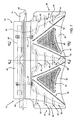
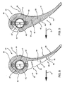
- each wall 39 has weakened portions to promote elastic deformation in given areas. More specifically, each wall 39 has a face 40; a face 41 opposite face 40 ( Figures 8, 9 ); and three grooves 42, 43, 44 formed, parallel to front bar 10, along face 40, and defining weakened portions of wall 39.
- Faces 40 of walls 39 are substantially triangular, with a vertex of the triangle facing bench 7 ( Figure 6 ), and one side adjacent to anchoring portion 37.
- each wall 39 is crosswise to travelling direction D, and gets thinner away from anchoring portion 37; grooves 42, 43, 44 get shallower away from anchoring portion 37; and walls 39 are curved - in the example shown, face 40 is convex, and face 41 concave.
- Anchoring portion 37 comprises a tubular member 45, which has a longitudinal slit 46 by which to insert front bar 10, and is fixed to front bar 10 by bolts 47.
- Anchoring portion 37 also comprises a finned plate 48 and a plate 49, which are incorporated in tubular member 45 to increase the rigidity of tubular member 45, and are engaged by bolts 47, which also engage front bar 10.
- each flexible sheet 36 is located between two walls 39, is characterized by being substantially thinner than the root of walls 39, as shown more clearly in Figures 8 and 9 , and has a knurled face 50 to increase friction with the thighs 33 of passenger 32 ( Figures 5, 6 ).
- flexible sheets 36 wrap about the thighs 33 of passenger (dummy) 32, and walls 39 are positioned and deform partly on respective sides of thighs 33. Deformation is elastic and concentrated in the areas of walls 39 in which grooves 42, 43, 44 are formed ( Figure 7 ). With reference to Figures 8 and 9 , elastic deformation is actually determined by stress perpendicular to or having components perpendicular to face 40, and causes flaring of grooves 42, 43, 44. Conversely, stress directed towards face 41 immediately closes grooves 42, 43, 44, so that wall 39 acts as a substantially rigid member.
- Safety barrier 34 is flat, to form a sort of shield in front of the passenger. This shield ensures a high degree of safety by virtue of the large area covered, performs rigidly to prevent the passenger from falling (sliding off between the bench and front bar), but flexes in response to other than falling passenger movements, thus combining both passenger safety and comfort.
- safety barrier 34 is relatively compact, and is easy to produce and install, even on transportation units not originally designed for this type of fixture.
Landscapes
- Engineering & Computer Science (AREA)
- Transportation (AREA)
- Mechanical Engineering (AREA)
- Seats For Vehicles (AREA)
- Ropes Or Cables (AREA)
- Electric Cable Arrangement Between Relatively Moving Parts (AREA)
Description
- The present invention relates to a transportation unit for cable transportation systems.
- A cable transportation system comprises a number of transportation units movable between at least two turnaround stations, and normally comprising cars or chairs. A cable transportation system comprising only cars is known as a cable-car, and one comprising only chairs is known as a chair-lift. In recent years, combination cable transportation systems comprising both chairs and cars have also become popular.
- Chair-lifts, or any cable transportation system comprising chairs, involve safety issues, to prevent passengers from falling off.
- A chair-lift transportation unit normally comprises a supporting frame attached to a draw cable; and a chair comprising a bench and a backrest. To prevent passengers from falling off the chair, each transportation unit is equipped with a safety frame hinged to the supporting frame and movable between a closed position and an open position allowing passengers on and off the chair. The safety frame comprises a front bar which, in the closed position, is located over the bench and in front of the backrest, to prevent passengers from falling off.
- Some transportation units comprise locking devices for locking the safety frame in the closed position along the route between the turnaround stations, and only releasing the safety frame along the route inside the turnaround stations.
- The safety frame and locking devices have done a lot to improve the safety of chair-lifts, but concern over passengers falling off still remains, owing to the safety frame and locking devices failing to prevent passengers from slipping off between the bench and the front bar, even when this is in the closed position. Incidents of this sort mainly involve passengers of small build, such as children, on account of the chairs, and therefore the distance between the front bar and the bench, normally being designed for adult passengers of medium build.
- Various solutions have been proposed to at least partly solve the problem of passengers falling off the chair.
- A first solution, chronologically, consists in fixing safety barriers to the front bar, as shown on
page 10, Figure 16 of the No. 2/1989 issue of Rivista Internazionale delle Funivie, or onpage 15,Figure 6 of the No. 5/1989 issue of Revue Internationale des Téléphériques. - The above magazines are substantially two issues of the same magazine in different languages, and show the same photograph of a chair produced by the Swiss company Von Roll, and wherein the safety barriers comprise brackets fixed to the front bar. Each bracket is located in front of and centrally with respect to a respective passenger seat, and extends between the front bar and the bench and centrally with respect to the passenger seat when the safety frame is in the closed position. In actual use, the safety barrier is located at least partly between the passenger's thighs, to prevent the passenger from falling off.
- This technical solution was later taken up by the Swiss company Garaventa in Patent
AT 411, 046 B - Other solutions proposed by Innova Patent GmbH in Patent
EP 1,721,801 B1 substantially all comprise a safety barrier having a contact surface located under and extending parallel to the front bar, and pressed elastically against the legs of the passenger/s sitting in the chair. - The safety barriers described in Patent
EP 1,721,801 B1 are characterized by adapting elastically to the passenger's build, but are sometimes expensive to produce, call for careful maintenance, cause a certain amount of discomfort by exerting concentrated pressure on a small area of the passenger's thighs, and may give rise to lateral buckling under combined bending and compressive stress, when the movable member is not guided properly. - Generally speaking, all known solutions pose drawbacks in terms of passenger comfort.
- It is an object of the present invention to provide a transportation unit for cable transportation systems, which is highly effective in preventing passengers from falling off, and at the same time provides for a high degree of comfort for passengers of any build.
- According to the present invention, there is provided a transportation unit for cable transportation systems, wherein the transportation unit is movable in a travelling direction, and comprises a chair with a bench; a safety frame movable between an open position and a closed position and comprising a front bar; and at least one safety barrier, which is fixed to the front bar, extends predominantly between the front bar and the bench when the safety frame is in the closed position, and comprises a support with an anchoring portion fixed to the front bar, and at least one projecting portion, which projects from the anchoring portion, characterized in that the at least one projecting portion is elastically flexible under stress oriented in given directions, and is substantially rigid under stress oriented in other directions.
- The barrier can be located centrally with respect to a seat on the bench, and, being flexible under stress in given directions, causes no injury to passengers in the event of accidental contact, and reduces the section through which the passenger's body could otherwise slip accidentally off the bench. Moreover, flexibility is easily controllable and poses no lateral buckling problems.
- In a preferred embodiment of the present invention, the projecting portion comprises at least one wall crosswise to the travelling direction, integral with the anchoring portion, and having at least one weakened portion to promote flexibility of the projecting portion and so define the given stress directions.
- The flexibility of the projecting portion can thus be controlled easily, to achieve a good safety-comfort compromise for passengers of any build.
- A number of non-limiting embodiments of the present invention will be described by way of example with reference to the accompanying drawings, in which:
-
Figure 1 shows a schematic front view, with parts removed for clarity, of a transportation unit of a cable transportation system, in accordance with the present invention; -
Figure 2 shows a larger-scale section, with parts removed for clarity, of a detail of theFigure 1 transportation unit; -
Figure 3 shows a larger-scale view in perspective, with parts removed for clarity, of a detail of theFigure 1 transportation unit; -
Figure 4 shows a larger-scale view in perspective, with parts removed for clarity, of a detail of theFigure 1 transportation unit; -
Figure 5 shows a side view, with parts removed for clarity, of a second embodiment of a transportation unit in accordance with the present invention; -
Figure 6 shows a front view, with parts removed for clarity, of theFigure 5 transportation unit; -
Figure 7 shows a larger-scale front view, with parts removed for clarity, of a detail of theFigure 5 transportation unit; -
Figures 8 and 9 show sections of theFigure 7 detail, with parts removed for clarity, along lines VIII-VIII and IX-IX respectively. - Number 1 in
Figure 1 indicates as a whole a transportation unit of a cable transportation system, of whichFigure 1 shows a draw cable 2. - Transportation unit 1 is movable in a travelling direction D (
Figure 2 ), and comprises a supportingstructure 3 attached to draw cable 2; a trolley 4 fixed to supportingstructure 3; achair 5 fitted to supportingstructure 3; and asafety frame 6 mounted to rotate about an axis A1 with respect to supportingstructure 3. -
Chair 5 comprises a bench 7 - in the example shown, abench 7 with eight seats 8 - and abackrest 9; and eachseat 8 is formed ergonomically in the body ofbench 7. -
Safety frame 6 comprises afront bar 10 extending along an axis A2 parallel to axis A1; and twoside bars 11, each connectingfront bar 10 to arespective hinge 12 atbackrest 9. -
Safety frame 6 comprises four foot-rest devices 13 equally spaced alongfront bar 10, and each comprising ahub 14, a supportingbar 15, and a foot-rest 16.Hub 14 is fixed tofront bar 10 and connected by supportingbar 15 to foot-rest 16, which extends parallel tofront bar 10 and on opposite sides of supportingbar 15. - Alternatively,
hub 14 is mounted to rotate aboutfront bar 10, so foot-rest 16 can be adjusted even whensafety frame 6 is locked in the closed position. -
Safety frame 6 also comprises eightsafety barriers 17, each located at a seat 8 - more specifically, centrally with respect toseat 8 whensafety frame 6 is in the closed position, so that eachsafety barrier 17 extends partly between the legs of the passenger (not shown inFigure 1 ). - Each
safety barrier 17 is fixed tofront bar 10, and comprises asleeve 18 fitted aboutfront bar 10; and aprojection 19 extending fromsleeve 18 towardsbench 7. Depending on requirements,projection 19 may be of different lengths, even to the point of the free end ofprojection 19 contactingbench 7, as shown by the dash line inFigure 1 . Generally speaking, the free end of the projection faces inwards ofchair 5. - With reference to
Figure 4 ,safety barrier 17 comprises asupport 20, and acover 21 aboutsupport 20. -
Support 20 is fixed rigidly tofront bar 10, and cover 21 fully enclosessupport 20 and portions offront bar 10 adjacent to support 20. In other words, support 20supports cover 21, which is made of more elastic material than support 20. In addition,cover 21 is elastically deformable in any direction, whereas support 20 only flexes elastically under stress oriented in given directions. Preferably,support 20 is made of polymer material, and cover 21 of polymer foam. And the flexibility ofsupport 20 is substantially determined by its geometry. - With reference to
Figure 3 ,support 20 comprises ananchoring portion 22 fixed to and extending parallel tofront bar 10; and a projectingportion 23, which projects from anchoringportion 22 towardsbench 7 whenframe 6 is in the closed position (Figure 1 ), is elastically flexible, and comprises awall 24 integral withanchoring portion 22, and awall 25 connectinganchoring portion 22 towall 24, and which is thinner and therefore more flexible thanwall 24.Wall 24 is weakened to promote elastic deformation at a given point ofsupport 20. More specifically,wall 24 has aface 26; aface 27opposite face 26; and agroove 28 formed alongface 27, close to anchoringportion 22, as shown more clearly inFigure 2 .Groove 28, in fact, defines the weakened portion ofwall 24, and is parallel tofront bar 10. - With reference to
Figure 2 ,anchoring portion 22,wall 24, andwall 25 define a gap, andgroove 28 promotes flexing ofwall 24 under stress oriented in given directions, which, in the example shown, are any directions towardsface 26 ofwall 24 and which have at least one component perpendicular to face 26. Generally speaking,wall 24 curves about the weakened portion under stress oriented at least partly perpendicular to and towardsface 26. Under such stress,wall 24 curves, flexes about the weakened portion, and also causes flexing ofwall 25, which, being thinner, opposes no resistance. - Under stress in the opposite direction to the one described,
wall 25 acts as a tie, preventing flexing ofwall 24. - With reference to
Figure 3 ,walls portion 22, and are integral with each other at their respective free ends. - Anchoring
portion 22 comprises two half-shells front bar 10 and fitted together, to gripfront bar 10, by means of screws or other fasteners not shown in the drawings. In the example shown,walls shell 29. - In other words, the geometry of
support 20 permits flexing of projectingportion 23. More specifically, the location ofgroove 28 determines the flexing path and direction of projectingportion 23; and the amount by which projectingportion 23 flexes is substantially determined by the depth and width ofgroove 28. - Elastic deformation under stress of
support 20 ofsafety barrier 17 can thus be controlled, to achieve transportation units 1 which ensure effective fall prevention combined with a high degree of passenger comfort. - Though specific reference is made herein to a
chair 5 with eightseats 8, it is understood that the present invention also applies to transportation units comprising any number of seats. -
Number 31 inFigures 5 and 6 indicates as a whole a transportation unit with structural parts similar to those of transportation unit 1, and which, for the sake of simplicity, are therefore indicated using the same reference numbers as inFigure 1 . -
Figures 5 and 6 also show apassenger 32 in the form of a dummy having twothighs 33 and seated in aseat 8 oftransportation unit 31. - For each
seat 8,transportation unit 31 comprises asafety barrier 34 which, in use, extends partly about thethighs 33 of passenger (dummy) 32. - With reference to
Figure 7 ,safety barrier 34 comprises asupport 35; and twoflexible sheets 36 integral with each other and formed integral withsupport 35. -
Support 35 is fixed rigidly tofront bar 10, is flexible under stress oriented in given directions, and is substantially rigid under stress in other directions. -
Support 35 andflexible sheets 36 are preferably formed integral with one another from polymer material. In a preferred embodiment,support 35 andflexible sheets 36 are formed integral with one another, with a shell of polymer material filled with foam material. The flexibility ofsupport 35 is substantially determined by its geometry. - In the example shown,
support 35 comprises an anchoringportion 37 fixed to and extending parallel tofront bar 10; and three projectingportions 38, each of which projects from anchoringportion 37 towardsbench 7 whenframe 6 is in the closed position (Figure 6 ), is flexible, and comprises awall 39 integral with anchoringportion 37. Projectingportions 38 are arranged along axis A2, and eachflexible sheet 36 is located between two projectingportions 38. As shown inFigure 5 , projectingportions 38 face inwards ofchair 5. - Each
wall 39 has weakened portions to promote elastic deformation in given areas. More specifically, eachwall 39 has aface 40; aface 41 opposite face 40 (Figures 8, 9 ); and threegrooves front bar 10, alongface 40, and defining weakened portions ofwall 39. -
Faces 40 ofwalls 39 are substantially triangular, with a vertex of the triangle facing bench 7 (Figure 6 ), and one side adjacent to anchoringportion 37. - With reference to
Figures 8 and 9 , eachwall 39 is crosswise to travelling direction D, and gets thinner away from anchoringportion 37;grooves portion 37; andwalls 39 are curved - in the example shown,face 40 is convex, and face 41 concave. - Anchoring
portion 37 comprises atubular member 45, which has alongitudinal slit 46 by which to insertfront bar 10, and is fixed tofront bar 10 bybolts 47. Anchoringportion 37 also comprises afinned plate 48 and aplate 49, which are incorporated intubular member 45 to increase the rigidity oftubular member 45, and are engaged bybolts 47, which also engagefront bar 10. - With reference to
Figure 7 , eachflexible sheet 36 is located between twowalls 39, is characterized by being substantially thinner than the root ofwalls 39, as shown more clearly inFigures 8 and 9 , and has aknurled face 50 to increase friction with thethighs 33 of passenger 32 (Figures 5, 6 ). - With reference to
Figure 6 , in actual use,flexible sheets 36 wrap about thethighs 33 of passenger (dummy) 32, andwalls 39 are positioned and deform partly on respective sides ofthighs 33. Deformation is elastic and concentrated in the areas ofwalls 39 in whichgrooves Figure 7 ). With reference toFigures 8 and 9 , elastic deformation is actually determined by stress perpendicular to or having components perpendicular to face 40, and causes flaring ofgrooves face 41 immediately closesgrooves wall 39 acts as a substantially rigid member. -
Safety barrier 34 is flat, to form a sort of shield in front of the passenger. This shield ensures a high degree of safety by virtue of the large area covered, performs rigidly to prevent the passenger from falling (sliding off between the bench and front bar), but flexes in response to other than falling passenger movements, thus combining both passenger safety and comfort. - Despite covering a large area,
safety barrier 34 is relatively compact, and is easy to produce and install, even on transportation units not originally designed for this type of fixture. - The present invention obviously also covers embodiments not described herein and equivalent embodiments, which nevertheless fall within the protective scope of the accompanying Claims.
Claims (15)
- A transportation unit for cable transportation systems, wherein the transportation unit (1) is movable in a travelling direction (D), and comprises a chair (5) with a bench (7); a safety frame (6) movable between an open position and a closed position and comprising a front bar (10); and at least one safety barrier (17; 34), which is fixed to the front bar (20), extends predominantly between the front bar (10) and the bench (7) when the safety frame (6) is in the closed position, and comprises a support (20; 35) with an anchoring portion (22; 37) fixed to the front bar (10), and at least one projecting portion (23; 38), which projects from the anchoring portion (22; 37), characterized in that the at least one projecting portion (23; 38) is elastically flexible under stress oriented in given directions, and is substantially rigid under stress oriented in other directions.
- A transportation unit as claimed in Claim 1, wherein the projecting portion (23; 38) comprises a wall (24; 39) crosswise to said travelling direction (D) and having at least one weakened portion to promote flexibility of said projecting portion (23; 38).
- A transportation unit as claimed in Claim 2, wherein the weakened portion is defined by a groove (28; 42, 43, 44) preferably parallel to the front bar (10).
- A transportation unit as claimed in Claim 3, wherein the wall (24; 39) comprises at least one face (27; 40); said groove (28; 42, 43, 44) being formed in the wall (24; 39), along said face (27; 40).
- A transportation unit as claimed in any one of the foregoing Claims, wherein the projecting portion (23; 38) is elastically flexible about at least one axis parallel to the front bar (10).
- A transportation unit as claimed in any one of the foregoing Claims, wherein the projecting portion (23; 38) has a free end facing inwards of said chair (5) when said safety frame (6) is in the closed position.
- A transportation unit as claimed in any one of the foregoing Claims, wherein the chair (5) has a given number of seats (8), and a given number of safety barriers (17; 34) equal to the number of seats (8); each safety barrier (17; 34) being located centrally with respect to a respective seat (8) when the safety frame (6) is in the closed position.
- A transportation unit as claimed in any one of the foregoing Claims, wherein the free end of the safety barrier (17; 34) is positioned contacting the bench (7) when said safety frame (6) is in the closed position.
- A transportation unit as claimed in any one of the foregoing Claims, wherein the support (20; 35) is made of polymer material.
- A transportation unit as claimed in any one of Claims 2 to 9, wherein the projecting portion (23) comprises a further wall (25) facing the wall (24) and connecting the anchoring portion (22) to the wall (24); and the anchoring portion (22), the wall (24), and the further wall (25) preferably define a gap.
- A transportation unit as claimed in Claim 10, wherein the further wall (25) is thinner than the wall (24).
- A transportation unit as claimed in Claim 10 or 11, wherein the wall (24) and the further wall (25) are trapezoidal and integral with the anchoring portion (22).
- A transportation unit as claimed in any one of Claims 10 to 12, wherein the safety barrier comprises a cover (21) enclosing said support (20); the cover (21) preferably encloses parts of the front bar (10) adjacent to the support (20); and said cover (21) is preferably made of polymer foam.
- A transportation unit as claimed in any one of Claims 2 to 9, wherein the support (35) has three projecting portions (38) which are positioned alongside the thighs (33) of a passenger (32); each projecting portion (38) preferably being defined by a respective wall (39) having three weakened portions defined by respective grooves (42, 43, 44).
- A transportation unit as claimed in Claim 14, wherein the safety barrier comprises two flexible sheets (36) which are positioned contacting the thighs (33) of the passenger (32); each flexible sheet (36) extending between two projecting portions (38).
Applications Claiming Priority (2)
| Application Number | Priority Date | Filing Date | Title |
|---|---|---|---|
| ITMI2009A001214A IT1395098B1 (en) | 2009-07-09 | 2009-07-09 | TRANSPORT UNIT FOR ROPE TRANSPORT SYSTEMS |
| PCT/EP2010/055640 WO2011003639A1 (en) | 2009-07-09 | 2010-04-27 | Transportation unit for cable transportation systems |
Publications (2)
| Publication Number | Publication Date |
|---|---|
| EP2451689A1 EP2451689A1 (en) | 2012-05-16 |
| EP2451689B1 true EP2451689B1 (en) | 2013-08-07 |
Family
ID=41666477
Family Applications (1)
| Application Number | Title | Priority Date | Filing Date |
|---|---|---|---|
| EP10715844.6A Active EP2451689B1 (en) | 2009-07-09 | 2010-04-27 | Transportation unit for cable transportation systems |
Country Status (7)
| Country | Link |
|---|---|
| US (2) | US8991317B2 (en) |
| EP (1) | EP2451689B1 (en) |
| KR (1) | KR101687993B1 (en) |
| CN (1) | CN102498022B (en) |
| ES (1) | ES2431067T3 (en) |
| IT (1) | IT1395098B1 (en) |
| WO (1) | WO2011003639A1 (en) |
Families Citing this family (3)
| Publication number | Priority date | Publication date | Assignee | Title |
|---|---|---|---|---|
| CH704870A2 (en) * | 2011-04-29 | 2012-10-31 | Bartholet Maschb Ag | Safety device for cableway chair. |
| JP6376925B2 (en) * | 2014-09-29 | 2018-08-22 | 日本ケーブル株式会社 | Fall prevention device for chairlift carrier |
| AT524942B1 (en) * | 2021-06-25 | 2022-11-15 | Innova Patent Gmbh | cable car vehicle |
Family Cites Families (119)
| Publication number | Priority date | Publication date | Assignee | Title |
|---|---|---|---|---|
| US472211A (en) | 1892-04-05 | Half to louis a | ||
| DE423865C (en) | 1925-02-28 | 1926-01-12 | Karl Laissle Dipl Ing | Rope carrying device |
| US1944446A (en) | 1932-05-27 | 1934-01-23 | Mckay Co | Swing |
| FR891743A (en) | 1941-11-25 | 1944-03-17 | Pohlig J Ag | Control for cable cars |
| FR913146A (en) | 1945-08-06 | 1946-08-29 | Multi-skip cable car, continuous operation, for travelers | |
| CH259291A (en) | 1947-02-21 | 1949-01-15 | Eisen Und Stahlwerke Oehler & | Safety device on suspension railway systems. |
| US2662587A (en) | 1949-11-18 | 1953-12-15 | Mcilvaine Alexander | Chair for aerial skilifts |
| FR1100001A (en) | 1954-02-19 | 1955-09-15 | Air Carrier Improvements | |
| US2710650A (en) | 1954-03-19 | 1955-06-14 | Riblet Tramway Company | Aerial ski lift chair |
| US2985224A (en) | 1958-03-28 | 1961-05-23 | Riblet Tramway Company | Aerial lift passenger chair |
| FR1199721A (en) | 1958-06-20 | 1959-12-16 | Upgrades to Cable Carriers | |
| CH360704A (en) | 1960-03-15 | 1962-03-15 | Mayor Henry | Safety device for an air carrier cable |
| US3170412A (en) | 1963-05-06 | 1965-02-23 | Ribiet Tramway Company | Chair swing damper |
| FR1423648A (en) | 1963-05-10 | 1966-01-07 | Doppelmayr & Sohn | Safety device for ropeways, in particular for single-cable ropeways |
| GB1326264A (en) | 1969-10-29 | 1973-08-08 | Krampe Co Fertigund In Bergbau | Railway track and vehicles for use in underground mining |
| DE2020746C3 (en) | 1970-04-28 | 1979-03-08 | Fritz 6685 Schiffweiler Leh | Cable guide station for rail-mounted industrial trucks |
| AT315910B (en) | 1970-08-21 | 1974-06-25 | Waagner Biro Ag | Pull rope vibration damper |
| DE2101743A1 (en) | 1971-01-15 | 1972-09-07 | Maschinenfabrik Scharf Gmbh, 4700 Hamm | Roller block with a controlled forced guidance for the pull rope of a cableway laid in particular in mining conveyor lines |
| IT960071B (en) | 1972-05-17 | 1973-11-20 | Gatti G | PROGRESSIVE ACTION REEL WITH MAGNETIC BRAKE FOR MONO OR MULTI-SEATER TOWING DEVICES FOR SKIVES |
| CH554761A (en) | 1972-11-03 | 1974-10-15 | Streiff Mathias | DEVICE FOR FASTENING PULL ROPE ROLLERS, TRAILER AND / OR GUIDE RAILS AND STAIRS TO RAMP OF FUNCTIONAL RAILWAYS. |
| DE2260366A1 (en) * | 1972-12-09 | 1974-07-04 | Braun Ag | SAFETY DEVICE FOR MOTOR VEHICLES, IN PARTICULAR FOR THE PROTECTION OF CHILDREN AND YOUNG PEOPLE |
| CH563902A5 (en) | 1973-11-20 | 1975-07-15 | Habegger Willy | |
| GB1460106A (en) | 1974-05-22 | 1976-12-31 | Coal Industry Patents Ltd | Method of propulsion of vehicles |
| CH591351A5 (en) | 1975-10-24 | 1977-09-15 | Habegger Willy | |
| FR2340895A1 (en) | 1976-02-12 | 1977-09-09 | Pomagalski Sa | Support guide for ski hoist cable - has two pairs of rollers with tyres angled to contact at top and support cable but pass tow brackets |
| AT342655B (en) | 1976-06-14 | 1978-04-10 | Waagner Biro Ag | ROPE VIBRATION DAMPER FOR ROPE SYSTEMS |
| JPS5810264B2 (en) | 1976-08-31 | 1983-02-24 | 日産自動車株式会社 | Vehicle running stability mechanism in overhead cableway system |
| AT344786B (en) * | 1976-11-09 | 1978-08-10 | Schaller Herbert Christian Dr | CHILD SEAT FOR THE ACCOMMODATION AND CARRIAGE OF IN PARTICULAR SMALL CHILDREN IN CHAIR LIFT CHAIRS |
| FR2416148A1 (en) | 1978-02-01 | 1979-08-31 | Pomagalski Sa | SAFETY DEVICE FOR A BALANCER FOR SUPPORTING AN OVERHEAD CABLE OF A TRANSPORTATION INSTALLATION |
| FR2387830A1 (en) | 1977-04-22 | 1978-11-17 | Pomagalski Sa | Monorail cable railway roller safety mechanism - has cutters activated by rockers to cut wire and break electric circuit |
| FR2392858A1 (en) | 1977-05-12 | 1978-12-29 | Mautino Victor | Haulage and supporting rope roller set - has support rocker with eye at end to receive end rope which is tensioned by spring |
| FR2391450A1 (en) | 1977-05-18 | 1978-12-15 | Stgm | Position of traction cable checking system - uses probe signalling when cable derailment on balancing pulley assembly occurs |
| US4470355A (en) | 1977-11-14 | 1984-09-11 | Kunczynski Jan K | Pneumatic cable tensioning apparatus and method for an aerial tramway or the like |
| DE2811336A1 (en) | 1978-03-16 | 1979-09-20 | Scharf Gmbh Maschf | ROPE OPERATED TRANSPORT RAILWAY |
| US4226187A (en) | 1978-10-23 | 1980-10-07 | Sdi Welding Corporation | Ski lift apparatus and safety device |
| JPS5599456A (en) | 1979-01-25 | 1980-07-29 | Nissan Motor | Suspension mechanism of aerial track car |
| FR2496579A1 (en) | 1980-12-22 | 1982-06-25 | Pomagalski Sa | BICABLE TELEPHERIC |
| DE3109294A1 (en) | 1981-03-11 | 1982-10-14 | Muckenhaupt GmbH, 4320 Hattingen | Conveyor system with traction cable for underground mining operations |
| DE3109944C2 (en) | 1981-03-14 | 1984-02-02 | PHB Weserhütte AG, 5000 Köln | Detachable circulating cable car for the transport of material, such as bulk goods |
| AT373832B (en) | 1981-04-21 | 1984-02-27 | Nejez Josef Dipl Ing Dr Techn | SAFETY DEVICE FOR MONITORING THE ROPE OF EARTHED CONDUCTOR ROPES ON ROLLER BATTERIES OF CABLE CARS AND TOW LIFTS |
| US4462314A (en) | 1982-02-05 | 1984-07-31 | Kunczynski Jan K | Rocker arm assembly for an aerial tramway |
| CH656357A5 (en) | 1983-07-04 | 1986-06-30 | Vevey Atel Const Mec | SUSPENDED MOTOR VEHICLE. |
| IT8322994U1 (en) | 1983-09-16 | 1985-03-16 | Leitner Spa | CENTRIFUGAL BRAKE FOR PROGRESSIVE ACTION TOWING DEVICE FOR SKI LIFTS. |
| AT379781B (en) | 1984-03-22 | 1986-02-25 | Doppelmayr & Sohn | BRAKE, ESPECIALLY FOR TOWING DEVICES OF TOW ROPES FOR TOW LIFTS |
| FR2562857B1 (en) | 1984-04-13 | 1987-01-16 | Pomagalski Sa | BALANCERS OF AN AIR CABLE TRANSPORTATION SYSTEM |
| AT385480B (en) | 1985-09-11 | 1988-04-11 | Doppelmayr & Sohn | UNDERCARRIAGE CARRIERS FOR CABLE CARS, IN PARTICULAR FOR ONE-ROPE CABLE CARS |
| US4671187A (en) | 1985-09-20 | 1987-06-09 | Kunczynski Jan K | Deropement sensor apparatus with gravity-biased, falling, magnetic member |
| IT206251Z2 (en) | 1985-10-09 | 1987-07-13 | Leitner Spa | CUSHIONED INVITATION GUIDE FOR FUNICIAL VEHICLES. |
| AT385007B (en) | 1986-04-07 | 1988-02-10 | Voest Alpine Ag | CHASSIS FOR A FUNCTIONAL CABLE CAR |
| FR2604675B1 (en) | 1986-10-02 | 1988-12-30 | Pomagalski Sa | AIR TRANSPORTATION SYSTEM WITH TWO CARRIER-TRACTOR CABLES WITH OFFSET PULLEYS |
| US4858997A (en) * | 1986-12-31 | 1989-08-22 | Shubin Steven A | Child safety car seat |
| IT1207747B (en) | 1987-03-06 | 1989-06-01 | Lettner S P A | TELEPHONE SYSTEM WITH DEVIATION OF THE TRAENT ROPE PATH. |
| FR2612144B1 (en) | 1987-03-11 | 1991-09-06 | Pomagalski Sa | AIR TRANSPORTATION SYSTEM WITH TWO CARRIER-TRACTOR CABLES WITH VERTICALLY OFFSET PULLEYS |
| DE3834116A1 (en) | 1987-11-04 | 1989-05-24 | Scharf Gmbh Maschf | Arrangement for guiding a traction cable |
| AT388146B (en) | 1988-01-08 | 1989-05-10 | Engel Edwin Dipl Ing Dr Techn | Method and devices for automatically monitoring the position of the hauling cables of cableways and T-bar lifts on a cable carrying roller |
| AT389087B (en) | 1988-04-06 | 1989-10-10 | Stemag Steirische Maschinen Un | Brake, in particular for retraction devices for towing cables in T-bar lifts |
| US4909574A (en) * | 1988-11-14 | 1990-03-20 | Century Products Company | Child's car seat restraint system |
| CH676356A5 (en) | 1988-12-09 | 1991-01-15 | Ortlinghaus Ag | |
| AT390926B (en) | 1989-03-14 | 1990-07-25 | Swoboda Seilbahnbau Gmbh | Device for monitoring the position of a haulage cable of an aerial cableway or of a draglift on a cable pulley |
| DE3927757C1 (en) | 1989-08-23 | 1991-03-28 | Kloeckner-Becorit Gmbh, 4620 Castrop-Rauxel, De | Wagon rope haulage system - uses single flange rollers on spring-loaded levers |
| AT393479B (en) | 1990-03-08 | 1991-10-25 | Waagner Biro Ag | CONNECTION OF CABLE CAR |
| NL9001040A (en) * | 1990-05-01 | 1991-12-02 | Linido Bv | DISABLED CHAIR. |
| FR2670452A1 (en) | 1990-12-18 | 1992-06-19 | Pomagalski Sa | Device for damping out the oscillations in the hauling cable of a ropeway (cableway, telepherique) |
| FR2670451A1 (en) | 1990-12-18 | 1992-06-19 | Pomagalski Sa | CABLE CLUTCH OR CABLE LIFT WITH TWO CABLE LOOPS. |
| US5113768A (en) | 1991-03-15 | 1992-05-19 | Brown Garrett W | Cable-suspended apparatus for supporting a stabilized camera assembly |
| FR2676981B1 (en) | 1991-06-03 | 1993-08-27 | Pomagalski Sa | SAFETY DEVICE OF AN AIR CABLE TRANSPORTATION INSTALLATION. |
| DE4127373A1 (en) | 1991-08-19 | 1993-02-25 | Wolf Von Bodisco | Suspended railway allowing continuous, frequent flow of transporting cabins - uses bidirectional cabins crossing at stations and having ceiling-mounted clamp arms gripping motor-driven rope loop |
| US5273314A (en) * | 1991-10-17 | 1993-12-28 | Toyota Jidosha Kabushiki Kaisha | Supporting bracket for knee panel |
| DE69231388T2 (en) | 1991-11-29 | 2001-01-25 | Cosmo System Corp., Matsumoto | Position detector in a transport device and drive controller for a transport element |
| FR2706404A1 (en) | 1993-06-09 | 1994-12-23 | Montagner Rene | Ski-lift installation |
| FR2709278B1 (en) | 1993-08-25 | 1995-10-27 | Pomagalski Sa | Device for stabilizing the clamps of a teleporter. |
| CA2143504A1 (en) | 1994-03-11 | 1995-09-12 | Ernst Egli | Rope guide system for an aerial ropeway, particularly a circuital aerial ropeway |
| DE9405016U1 (en) * | 1994-03-24 | 1994-06-01 | Riedling, Wolfgang, Dr., 41372 Niederkrüchten | Chairlift |
| FR2719011B1 (en) | 1994-04-22 | 1996-07-12 | Pomagalski Sa | Transport installation with tractor cable and on-board engine. |
| AT404010B (en) | 1994-06-09 | 1998-07-27 | Waagner Biro Ag | Truck, in particular pivoted bogie for a rail vehicle such as the wagon of a funicular railway |
| IT1270233B (en) | 1994-06-16 | 1997-04-29 | Leitner Spa | DOUBLE ACTION VICE FOR THE ROPE-RELEASE OF A FUNICULAR VEHICLE |
| IT1270234B (en) | 1994-06-16 | 1997-04-29 | Leitner Spa | RAILWAY AND TRAENT ROPE FUNICULAR SYSTEM, IN PARTICULAR FOR URBAN TRANSPORT, OF THE TYPE IN WHICH THE VEHICLES ARE EQUIPPED WITH A MOBILE JAW CLAMP FOR ATTACHING / RELEASING FROM THE TRACING ROPE |
| IT1276268B1 (en) | 1994-07-14 | 1997-10-28 | Hoelzl Costruzione Funivie Srl | HANDLING SYSTEM FOR CABLE SYSTEMS WITH TWO OR ONE RUNWAY AND PRESENTING CARRYING CABLES OR ROPES |
| DE19502226C1 (en) * | 1995-01-25 | 1996-05-09 | Daimler Benz Ag | Impact protection for interior of vehicles |
| AT403147B (en) | 1995-05-29 | 1997-11-25 | Girak Garaventa Gmbh | MECHANICAL ROPE DERAIL PROTECTION |
| AT405269B (en) | 1996-05-24 | 1999-06-25 | Waagner Biro Ag | Funicular railway |
| AU1138799A (en) | 1997-11-26 | 1999-06-16 | Litens Automotive Partnership | Load sensor |
| ATE255515T1 (en) | 1998-07-09 | 2003-12-15 | Ropetrans Ag | HOLDING DEVICE FOR A SUPPORT ROPE |
| US6065786A (en) * | 1998-07-22 | 2000-05-23 | Wheatley; Donald G. | Vehicle bumper assembly |
| US6036282A (en) | 1998-07-31 | 2000-03-14 | Zeftron, Inc. | Railcar air motor driven generator |
| IT1313108B1 (en) | 1999-08-18 | 2002-06-17 | Leitner Spa | MOBILE JAW VICE PERFECTED FOR THE HOOKING AND RELEASING OF VEHICLES TO A ROPE BETWEEN A TRANSPORT SYSTEM |
| IT1310249B1 (en) | 1999-09-24 | 2002-02-11 | Leitner Spa | DOUBLE ACTING ROLLER CONVEYOR FOR SINGLE WIRE ROPE SUPPORTS, IN PARTICULAR CHAIR LIFTS AND CABLEWAYS. |
| IT1313913B1 (en) | 1999-10-01 | 2002-09-26 | Leitner Spa | URBAN GUIDED TRANSPORT SYSTEM. |
| AT411046B (en) * | 1999-11-04 | 2003-09-25 | Girak Garaventa Gmbh | DEVICE FOR PROTECTING PASSENGERS ON A CHAIR OF A CABLE CAR |
| IT1316116B1 (en) | 2000-01-21 | 2003-03-28 | Leitner Spa | DEVICE FOR THE AUTOMATIC SETTING AND ADJUSTMENT OF THE FORZADI TRACTION OF A ROPE OF A WINCH OVERHEAD FOR A MACHINE |
| AT409253B (en) | 2000-07-20 | 2002-07-25 | Innova Patent Gmbh | PLANT FOR TRANSPORTING PERSONS AND METHOD FOR OPERATING SUCH A PLANT |
| US20020043829A1 (en) | 2000-10-04 | 2002-04-18 | Garaventa Holding Ag | Method and arrangement to close a bubble top for a chairlift |
| IT1316148B1 (en) | 2000-11-27 | 2003-03-28 | High Technology Invest Bv | MONITORING DEVICE FOR ROPE TRANSPORT SYSTEMS. |
| IT1316149B1 (en) | 2000-11-27 | 2003-03-28 | High Technology Invest Bv | CONTINUOUS ROPE TRACTION TRANSPORT PLANT WITH VEHICLES EQUIPPED WITH DAMAGING CLAMPING DEVICES. |
| FR2823482A1 (en) | 2001-04-11 | 2002-10-18 | Pomagalski Sa | Cableway transport system support and guide has two sets of rollers on curved beam pivoted to pylon |
| AT411523B (en) * | 2002-01-24 | 2004-02-25 | Innova Patent Gmbh | ARMCHAIR FOR A CABLE CAR |
| EP1364853A1 (en) | 2002-05-22 | 2003-11-26 | Pomagalski S.A. | Support and guiding device for the cable of a transport system |
| EP1419950A1 (en) | 2002-11-14 | 2004-05-19 | Innova Patent GmbH | Rope railway with swivelling cabins or seats |
| ITBZ20030005A1 (en) | 2003-01-30 | 2004-07-31 | High Technology Invest Bv | PRESSER DEVICE FOR CONDUCTING ROPE IN ROPE TRACTION TRANSPORT SYSTEMS. |
| AT411983B (en) | 2003-03-26 | 2004-08-26 | Edwin Dipl Ing Dr Techn Engel | Catching device for traction cable of cableway is displaced into catching position when critical cable limit is exceeded |
| FR2854853B1 (en) * | 2003-05-13 | 2013-07-19 | Pomagalski Sa | ANTI-FALL PROTECTION DEVICE FOR TELESIEGE SEATS |
| CN2631880Y (en) * | 2003-06-03 | 2004-08-11 | 张立坤 | Cable way cabin lifesaving apparatus |
| ITBZ20030050A1 (en) | 2003-10-03 | 2005-04-04 | High Technology Invest Bv | DRAINER FOR ROPE TRACKING ROPE ROPES. |
| FR2867142B1 (en) | 2004-03-08 | 2010-09-17 | Pomagalski Sa | DEVICE FOR SUPPORTING AND GUIDING A CARRIER-TRACTOR AIRCRAFT USING AN ELASTIC COUPLING LINK, AND MECHANICAL REMOTE INSTALLATION OF TELESIEGE OR TELECABINE TYPE COMPRISING SUCH A DEVICE |
| DE102004061627B4 (en) | 2004-12-17 | 2007-02-01 | Dorma Gmbh + Co. Kg | door closers |
| AT501824B1 (en) * | 2005-04-14 | 2007-01-15 | Innova Patent Gmbh | DEVICE FOR PROTECTING THE PASSENGERS ON THE ARMCHAIRS OF A LIFTING TREAD |
| ITMI20050800A1 (en) | 2005-05-03 | 2006-11-04 | Ferruccio Levi | MOVEMENT SYSTEM FOR FUNIVIARY SYSTEM INCLUDING TWO TRAENRI ROPES |
| ITBZ20050051A1 (en) | 2005-09-29 | 2007-03-30 | High Technology Invest Bv | ANTI-SCROLL-UP DEVICE FOR FUNPOSAL SYSTEM ROPES. |
| AT503887B1 (en) * | 2006-04-13 | 2008-08-15 | Innova Patent Gmbh | ARMCHAIR OF A SESSEL WITH ANTI-ABRUTSCHUICHERUNG |
| ITBZ20060036A1 (en) | 2006-08-16 | 2008-02-17 | High Technology Investments Bv | FALL ARREST DEVICE FOR CHAIRWAY CHAIRS WITH COMMAND COMMAND AND DISMANTLEMENT OF THE BARRIER. |
| AT504614B1 (en) * | 2006-12-04 | 2009-02-15 | Innova Patent Gmbh | CLOSING HANGER OF AN ARMCHAIR OF A SESSEL LIFT |
| ITMI20070157U1 (en) | 2007-04-20 | 2008-10-21 | Rolic Invest Sarl | CHAIRLIFT |
| ITMI20070835A1 (en) | 2007-04-20 | 2008-10-21 | Rolic Invest Sarl | ROPE TRANSPORTATION SYSTEM AND METHOD OF OPERATION OF THE SAME |
| DE202007006169U1 (en) | 2007-04-24 | 2007-07-12 | Stromag Ag | Brake/clutch unit, mounted at the main shaft of a cable car drive assembly, has a switched friction clutch between the drive section and the hub and a brake between the hub and a fixed base section |
| WO2009000059A1 (en) | 2007-06-26 | 2008-12-31 | Ziptrek Ecotours, Inc. | Continuous assist zipline braking and control system |
| US7410068B1 (en) | 2007-07-06 | 2008-08-12 | Agudio S.P.A. | Blondin cableway installation |
| ITMI20071618A1 (en) | 2007-08-03 | 2009-02-04 | Rolic Invest Sarl | ROPE TRANSPORTATION SYSTEM AND METHOD OF OPERATION OF THE SAME |
| ITMI20072071A1 (en) | 2007-10-26 | 2009-04-27 | Rolic Invest Sarl | ROPE TRANSPORTATION SYSTEM AND METHOD OF OPERATION OF THE SAME |
| EP2075172A1 (en) | 2007-12-28 | 2009-07-01 | Rolic Invest Sarl | Cableway system with supporting cables and a separate haulage cable |
-
2009
- 2009-07-09 IT ITMI2009A001214A patent/IT1395098B1/en active
-
2010
- 2010-04-27 US US13/382,778 patent/US8991317B2/en active Active
- 2010-04-27 EP EP10715844.6A patent/EP2451689B1/en active Active
- 2010-04-27 WO PCT/EP2010/055640 patent/WO2011003639A1/en not_active Ceased
- 2010-04-27 CN CN201080040337.5A patent/CN102498022B/en active Active
- 2010-04-27 KR KR1020127003410A patent/KR101687993B1/en active Active
- 2010-04-27 ES ES10715844T patent/ES2431067T3/en active Active
-
2015
- 2015-03-03 US US14/637,152 patent/US9738290B2/en active Active
Also Published As
| Publication number | Publication date |
|---|---|
| KR101687993B1 (en) | 2016-12-21 |
| US20120186485A1 (en) | 2012-07-26 |
| ES2431067T3 (en) | 2013-11-25 |
| CN102498022B (en) | 2014-11-05 |
| US20150175173A1 (en) | 2015-06-25 |
| KR20120059496A (en) | 2012-06-08 |
| IT1395098B1 (en) | 2012-09-05 |
| WO2011003639A1 (en) | 2011-01-13 |
| CN102498022A (en) | 2012-06-13 |
| WO2011003639A9 (en) | 2011-06-16 |
| US9738290B2 (en) | 2017-08-22 |
| ITMI20091214A1 (en) | 2011-01-10 |
| EP2451689A1 (en) | 2012-05-16 |
| US8991317B2 (en) | 2015-03-31 |
Similar Documents
| Publication | Publication Date | Title |
|---|---|---|
| KR102100080B1 (en) | Child seat and an impact shield for a child seat for a vehicle | |
| EP2368753B1 (en) | Child safety seat with energy absorbing apparatus | |
| KR20100040249A (en) | Chair of chair lift and chair lift | |
| US9738290B2 (en) | Transportation unit for cable transportation systems | |
| KR101420964B1 (en) | Manual wheelchair with automatic deceleration device in slope way | |
| KR101402186B1 (en) | Assistance seat belt for child | |
| KR100775371B1 (en) | Headrest positioning device | |
| KR20160125270A (en) | Multipurpose rear carrier for motorcycle | |
| KR102269951B1 (en) | Seat belt cushion device for Child | |
| JP6495942B2 (en) | Restraint member | |
| JP5963072B2 (en) | Railway vehicle. | |
| JP5229524B2 (en) | Vehicle seat structure | |
| KR101694020B1 (en) | Seat for vehicle having improved passenger' neck injury reduction performance | |
| JP5223074B2 (en) | Railway vehicle | |
| KR101382280B1 (en) | Apparatus for controlling webbing route of rear seat belt | |
| EP2108551B1 (en) | Belt system | |
| CN115246351B (en) | vehicle seat | |
| CN101500844A (en) | Advanced safety harness for child seat | |
| KR101767389B1 (en) | Reinforcing structure for seat | |
| KR19980029448U (en) | Front Seats for Disabled Cars | |
| KR20100060586A (en) | Transportation comfort chair for neck protection | |
| KR0137521Y1 (en) | Seat cushion of a car seat | |
| KR970004134Y1 (en) | Angle adjuster of seat headrest | |
| JP2015067152A (en) | Vehicle seat | |
| JPH0344933B2 (en) |
Legal Events
| Date | Code | Title | Description |
|---|---|---|---|
| PUAI | Public reference made under article 153(3) epc to a published international application that has entered the european phase |
Free format text: ORIGINAL CODE: 0009012 |
|
| 17P | Request for examination filed |
Effective date: 20120131 |
|
| AK | Designated contracting states |
Kind code of ref document: A1 Designated state(s): AT BE BG CH CY CZ DE DK EE ES FI FR GB GR HR HU IE IS IT LI LT LU LV MC MK MT NL NO PL PT RO SE SI SK SM TR |
|
| DAX | Request for extension of the european patent (deleted) | ||
| GRAP | Despatch of communication of intention to grant a patent |
Free format text: ORIGINAL CODE: EPIDOSNIGR1 |
|
| RAP1 | Party data changed (applicant data changed or rights of an application transferred) |
Owner name: ROLIC INTERNATIONAL S.A R.L. |
|
| GRAS | Grant fee paid |
Free format text: ORIGINAL CODE: EPIDOSNIGR3 |
|
| GRAA | (expected) grant |
Free format text: ORIGINAL CODE: 0009210 |
|
| AK | Designated contracting states |
Kind code of ref document: B1 Designated state(s): AT BE BG CH CY CZ DE DK EE ES FI FR GB GR HR HU IE IS IT LI LT LU LV MC MK MT NL NO PL PT RO SE SI SK SM TR |
|
| REG | Reference to a national code |
Ref country code: GB Ref legal event code: FG4D |
|
| REG | Reference to a national code |
Ref country code: CH Ref legal event code: EP Ref country code: AT Ref legal event code: REF Ref document number: 625616 Country of ref document: AT Kind code of ref document: T Effective date: 20130815 |
|
| REG | Reference to a national code |
Ref country code: IE Ref legal event code: FG4D |
|
| REG | Reference to a national code |
Ref country code: DE Ref legal event code: R096 Ref document number: 602010009203 Country of ref document: DE Effective date: 20131002 |
|
| REG | Reference to a national code |
Ref country code: ES Ref legal event code: FG2A Ref document number: 2431067 Country of ref document: ES Kind code of ref document: T3 Effective date: 20131125 |
|
| REG | Reference to a national code |
Ref country code: CH Ref legal event code: NV Representative=s name: HEPP WENGER RYFFEL AG, CH |
|
| REG | Reference to a national code |
Ref country code: NO Ref legal event code: T2 Effective date: 20130807 |
|
| REG | Reference to a national code |
Ref country code: NL Ref legal event code: VDEP Effective date: 20130807 |
|
| REG | Reference to a national code |
Ref country code: LT Ref legal event code: MG4D |
|
| PG25 | Lapsed in a contracting state [announced via postgrant information from national office to epo] |
Ref country code: CY Free format text: LAPSE BECAUSE OF FAILURE TO SUBMIT A TRANSLATION OF THE DESCRIPTION OR TO PAY THE FEE WITHIN THE PRESCRIBED TIME-LIMIT Effective date: 20130821 Ref country code: IS Free format text: LAPSE BECAUSE OF FAILURE TO SUBMIT A TRANSLATION OF THE DESCRIPTION OR TO PAY THE FEE WITHIN THE PRESCRIBED TIME-LIMIT Effective date: 20131207 Ref country code: SE Free format text: LAPSE BECAUSE OF FAILURE TO SUBMIT A TRANSLATION OF THE DESCRIPTION OR TO PAY THE FEE WITHIN THE PRESCRIBED TIME-LIMIT Effective date: 20130807 Ref country code: PT Free format text: LAPSE BECAUSE OF FAILURE TO SUBMIT A TRANSLATION OF THE DESCRIPTION OR TO PAY THE FEE WITHIN THE PRESCRIBED TIME-LIMIT Effective date: 20131209 Ref country code: LT Free format text: LAPSE BECAUSE OF FAILURE TO SUBMIT A TRANSLATION OF THE DESCRIPTION OR TO PAY THE FEE WITHIN THE PRESCRIBED TIME-LIMIT Effective date: 20130807 Ref country code: HR Free format text: LAPSE BECAUSE OF FAILURE TO SUBMIT A TRANSLATION OF THE DESCRIPTION OR TO PAY THE FEE WITHIN THE PRESCRIBED TIME-LIMIT Effective date: 20130807 |
|
| PG25 | Lapsed in a contracting state [announced via postgrant information from national office to epo] |
Ref country code: NL Free format text: LAPSE BECAUSE OF FAILURE TO SUBMIT A TRANSLATION OF THE DESCRIPTION OR TO PAY THE FEE WITHIN THE PRESCRIBED TIME-LIMIT Effective date: 20130807 Ref country code: SI Free format text: LAPSE BECAUSE OF FAILURE TO SUBMIT A TRANSLATION OF THE DESCRIPTION OR TO PAY THE FEE WITHIN THE PRESCRIBED TIME-LIMIT Effective date: 20130807 Ref country code: LV Free format text: LAPSE BECAUSE OF FAILURE TO SUBMIT A TRANSLATION OF THE DESCRIPTION OR TO PAY THE FEE WITHIN THE PRESCRIBED TIME-LIMIT Effective date: 20130807 Ref country code: PL Free format text: LAPSE BECAUSE OF FAILURE TO SUBMIT A TRANSLATION OF THE DESCRIPTION OR TO PAY THE FEE WITHIN THE PRESCRIBED TIME-LIMIT Effective date: 20130807 Ref country code: BE Free format text: LAPSE BECAUSE OF FAILURE TO SUBMIT A TRANSLATION OF THE DESCRIPTION OR TO PAY THE FEE WITHIN THE PRESCRIBED TIME-LIMIT Effective date: 20130807 Ref country code: FI Free format text: LAPSE BECAUSE OF FAILURE TO SUBMIT A TRANSLATION OF THE DESCRIPTION OR TO PAY THE FEE WITHIN THE PRESCRIBED TIME-LIMIT Effective date: 20130807 Ref country code: GR Free format text: LAPSE BECAUSE OF FAILURE TO SUBMIT A TRANSLATION OF THE DESCRIPTION OR TO PAY THE FEE WITHIN THE PRESCRIBED TIME-LIMIT Effective date: 20131108 |
|
| PG25 | Lapsed in a contracting state [announced via postgrant information from national office to epo] |
Ref country code: CY Free format text: LAPSE BECAUSE OF FAILURE TO SUBMIT A TRANSLATION OF THE DESCRIPTION OR TO PAY THE FEE WITHIN THE PRESCRIBED TIME-LIMIT Effective date: 20130807 |
|
| PG25 | Lapsed in a contracting state [announced via postgrant information from national office to epo] |
Ref country code: RO Free format text: LAPSE BECAUSE OF FAILURE TO SUBMIT A TRANSLATION OF THE DESCRIPTION OR TO PAY THE FEE WITHIN THE PRESCRIBED TIME-LIMIT Effective date: 20130807 Ref country code: CZ Free format text: LAPSE BECAUSE OF FAILURE TO SUBMIT A TRANSLATION OF THE DESCRIPTION OR TO PAY THE FEE WITHIN THE PRESCRIBED TIME-LIMIT Effective date: 20130807 Ref country code: DK Free format text: LAPSE BECAUSE OF FAILURE TO SUBMIT A TRANSLATION OF THE DESCRIPTION OR TO PAY THE FEE WITHIN THE PRESCRIBED TIME-LIMIT Effective date: 20130807 Ref country code: EE Free format text: LAPSE BECAUSE OF FAILURE TO SUBMIT A TRANSLATION OF THE DESCRIPTION OR TO PAY THE FEE WITHIN THE PRESCRIBED TIME-LIMIT Effective date: 20130807 Ref country code: SK Free format text: LAPSE BECAUSE OF FAILURE TO SUBMIT A TRANSLATION OF THE DESCRIPTION OR TO PAY THE FEE WITHIN THE PRESCRIBED TIME-LIMIT Effective date: 20130807 |
|
| PLBE | No opposition filed within time limit |
Free format text: ORIGINAL CODE: 0009261 |
|
| STAA | Information on the status of an ep patent application or granted ep patent |
Free format text: STATUS: NO OPPOSITION FILED WITHIN TIME LIMIT |
|
| 26N | No opposition filed |
Effective date: 20140508 |
|
| REG | Reference to a national code |
Ref country code: DE Ref legal event code: R097 Ref document number: 602010009203 Country of ref document: DE Effective date: 20140508 |
|
| PG25 | Lapsed in a contracting state [announced via postgrant information from national office to epo] |
Ref country code: LU Free format text: LAPSE BECAUSE OF FAILURE TO SUBMIT A TRANSLATION OF THE DESCRIPTION OR TO PAY THE FEE WITHIN THE PRESCRIBED TIME-LIMIT Effective date: 20140427 Ref country code: MC Free format text: LAPSE BECAUSE OF FAILURE TO SUBMIT A TRANSLATION OF THE DESCRIPTION OR TO PAY THE FEE WITHIN THE PRESCRIBED TIME-LIMIT Effective date: 20130807 |
|
| GBPC | Gb: european patent ceased through non-payment of renewal fee |
Effective date: 20140427 |
|
| REG | Reference to a national code |
Ref country code: IE Ref legal event code: MM4A |
|
| PG25 | Lapsed in a contracting state [announced via postgrant information from national office to epo] |
Ref country code: GB Free format text: LAPSE BECAUSE OF NON-PAYMENT OF DUE FEES Effective date: 20140427 |
|
| REG | Reference to a national code |
Ref country code: DE Ref legal event code: R082 Ref document number: 602010009203 Country of ref document: DE Representative=s name: MUELLER-BORE & PARTNER PATENTANWAELTE PARTG MB, DE |
|
| REG | Reference to a national code |
Ref country code: CH Ref legal event code: PUE Owner name: ROPFIN B.V., NL Free format text: FORMER OWNER: ROLIC INTERNATIONAL S.A R.L., LU |
|
| REG | Reference to a national code |
Ref country code: DE Ref legal event code: R081 Ref document number: 602010009203 Country of ref document: DE Owner name: ROPFIN B.V., NL Free format text: FORMER OWNER: ROLIC INTERNATIONAL S.A R.L., LUXEMBOURG, LU Effective date: 20150306 Ref country code: DE Ref legal event code: R082 Ref document number: 602010009203 Country of ref document: DE Representative=s name: MUELLER-BORE & PARTNER PATENTANWAELTE PARTG MB, DE Effective date: 20150306 Ref country code: DE Ref legal event code: R081 Ref document number: 602010009203 Country of ref document: DE Owner name: LEITNER S.P.A., VIPITENO, IT Free format text: FORMER OWNER: ROLIC INTERNATIONAL S.A R.L., LUXEMBOURG, LU Effective date: 20150306 |
|
| REG | Reference to a national code |
Ref country code: NO Ref legal event code: CHAD Owner name: ROPFIN B.V., NL |
|
| PG25 | Lapsed in a contracting state [announced via postgrant information from national office to epo] |
Ref country code: IE Free format text: LAPSE BECAUSE OF NON-PAYMENT OF DUE FEES Effective date: 20140427 |
|
| REG | Reference to a national code |
Ref country code: ES Ref legal event code: PC2A Owner name: ROPFIN B.V. Effective date: 20150512 |
|
| REG | Reference to a national code |
Ref country code: FR Ref legal event code: TP Owner name: ROPFIN B.V., NL Effective date: 20150527 |
|
| REG | Reference to a national code |
Ref country code: AT Ref legal event code: PC Ref document number: 625616 Country of ref document: AT Kind code of ref document: T Owner name: ROPFIN B.V., NL Effective date: 20151218 |
|
| REG | Reference to a national code |
Ref country code: FR Ref legal event code: PLFP Year of fee payment: 7 |
|
| PG25 | Lapsed in a contracting state [announced via postgrant information from national office to epo] |
Ref country code: MT Free format text: LAPSE BECAUSE OF FAILURE TO SUBMIT A TRANSLATION OF THE DESCRIPTION OR TO PAY THE FEE WITHIN THE PRESCRIBED TIME-LIMIT Effective date: 20130807 |
|
| PG25 | Lapsed in a contracting state [announced via postgrant information from national office to epo] |
Ref country code: SM Free format text: LAPSE BECAUSE OF FAILURE TO SUBMIT A TRANSLATION OF THE DESCRIPTION OR TO PAY THE FEE WITHIN THE PRESCRIBED TIME-LIMIT Effective date: 20130807 |
|
| PG25 | Lapsed in a contracting state [announced via postgrant information from national office to epo] |
Ref country code: BG Free format text: LAPSE BECAUSE OF FAILURE TO SUBMIT A TRANSLATION OF THE DESCRIPTION OR TO PAY THE FEE WITHIN THE PRESCRIBED TIME-LIMIT Effective date: 20130807 |
|
| PG25 | Lapsed in a contracting state [announced via postgrant information from national office to epo] |
Ref country code: HU Free format text: LAPSE BECAUSE OF FAILURE TO SUBMIT A TRANSLATION OF THE DESCRIPTION OR TO PAY THE FEE WITHIN THE PRESCRIBED TIME-LIMIT; INVALID AB INITIO Effective date: 20100427 |
|
| REG | Reference to a national code |
Ref country code: FR Ref legal event code: PLFP Year of fee payment: 8 |
|
| REG | Reference to a national code |
Ref country code: DE Ref legal event code: R082 Ref document number: 602010009203 Country of ref document: DE Representative=s name: MUELLER-BORE & PARTNER PATENTANWAELTE PARTG MB, DE Ref country code: DE Ref legal event code: R081 Ref document number: 602010009203 Country of ref document: DE Owner name: LEITNER S.P.A., VIPITENO, IT Free format text: FORMER OWNER: ROPFIN B.V., LEIMUIDEN, NL |
|
| REG | Reference to a national code |
Ref country code: NO Ref legal event code: CHAD Owner name: LEITNER S.P.A., IT |
|
| REG | Reference to a national code |
Ref country code: CH Ref legal event code: PUE Owner name: LEITNER S.P.A., IT Free format text: FORMER OWNER: ROPFIN B.V., NL |
|
| REG | Reference to a national code |
Ref country code: ES Ref legal event code: PC2A Owner name: LEITNER S.P.A. Effective date: 20180313 |
|
| REG | Reference to a national code |
Ref country code: FR Ref legal event code: PLFP Year of fee payment: 9 |
|
| REG | Reference to a national code |
Ref country code: AT Ref legal event code: PC Ref document number: 625616 Country of ref document: AT Kind code of ref document: T Owner name: LEITNER S.P.A., IT Effective date: 20180509 |
|
| PG25 | Lapsed in a contracting state [announced via postgrant information from national office to epo] |
Ref country code: MK Free format text: LAPSE BECAUSE OF FAILURE TO SUBMIT A TRANSLATION OF THE DESCRIPTION OR TO PAY THE FEE WITHIN THE PRESCRIBED TIME-LIMIT Effective date: 20130807 |
|
| REG | Reference to a national code |
Ref country code: FR Ref legal event code: TP Owner name: LEITNER S.P.A., IT Effective date: 20180605 |
|
| P01 | Opt-out of the competence of the unified patent court (upc) registered |
Effective date: 20230524 |
|
| PGFP | Annual fee paid to national office [announced via postgrant information from national office to epo] |
Ref country code: NO Payment date: 20230419 Year of fee payment: 14 Ref country code: ES Payment date: 20230510 Year of fee payment: 14 |
|
| PGFP | Annual fee paid to national office [announced via postgrant information from national office to epo] |
Ref country code: TR Payment date: 20230407 Year of fee payment: 14 |
|
| PG25 | Lapsed in a contracting state [announced via postgrant information from national office to epo] |
Ref country code: NO Free format text: LAPSE BECAUSE OF NON-PAYMENT OF DUE FEES Effective date: 20240430 |
|
| PG25 | Lapsed in a contracting state [announced via postgrant information from national office to epo] |
Ref country code: NO Free format text: LAPSE BECAUSE OF NON-PAYMENT OF DUE FEES Effective date: 20240430 |
|
| REG | Reference to a national code |
Ref country code: ES Ref legal event code: FD2A Effective date: 20250530 |
|
| PGFP | Annual fee paid to national office [announced via postgrant information from national office to epo] |
Ref country code: DE Payment date: 20250428 Year of fee payment: 16 |
|
| PG25 | Lapsed in a contracting state [announced via postgrant information from national office to epo] |
Ref country code: ES Free format text: LAPSE BECAUSE OF NON-PAYMENT OF DUE FEES Effective date: 20240428 |
|
| PGFP | Annual fee paid to national office [announced via postgrant information from national office to epo] |
Ref country code: IT Payment date: 20250403 Year of fee payment: 16 |
|
| PGFP | Annual fee paid to national office [announced via postgrant information from national office to epo] |
Ref country code: FR Payment date: 20250424 Year of fee payment: 16 |
|
| PGFP | Annual fee paid to national office [announced via postgrant information from national office to epo] |
Ref country code: CH Payment date: 20250501 Year of fee payment: 16 |
|
| PGFP | Annual fee paid to national office [announced via postgrant information from national office to epo] |
Ref country code: AT Payment date: 20250417 Year of fee payment: 16 |
|
| REG | Reference to a national code |
Ref country code: CH Ref legal event code: U11 Free format text: ST27 STATUS EVENT CODE: U-0-0-U10-U11 (AS PROVIDED BY THE NATIONAL OFFICE) Effective date: 20260501 |