EP2451525B1 - Apparatus for stimulating the lower back and abdominal muscles - Google Patents
Apparatus for stimulating the lower back and abdominal muscles Download PDFInfo
- Publication number
- EP2451525B1 EP2451525B1 EP10725182.9A EP10725182A EP2451525B1 EP 2451525 B1 EP2451525 B1 EP 2451525B1 EP 10725182 A EP10725182 A EP 10725182A EP 2451525 B1 EP2451525 B1 EP 2451525B1
- Authority
- EP
- European Patent Office
- Prior art keywords
- electrodes
- patient
- electrode
- garment
- pulses
- Prior art date
- Legal status (The legal status is an assumption and is not a legal conclusion. Google has not performed a legal analysis and makes no representation as to the accuracy of the status listed.)
- Not-in-force
Links
- 230000004936 stimulating effect Effects 0.000 title claims description 9
- 210000003489 abdominal muscle Anatomy 0.000 title claims description 6
- 210000003205 muscle Anatomy 0.000 claims description 17
- 230000008602 contraction Effects 0.000 claims description 14
- 230000000638 stimulation Effects 0.000 claims description 9
- 230000003387 muscular Effects 0.000 claims description 5
- 210000004705 lumbosacral region Anatomy 0.000 claims description 4
- 238000000034 method Methods 0.000 description 9
- 208000008930 Low Back Pain Diseases 0.000 description 7
- 238000002646 transcutaneous electrical nerve stimulation Methods 0.000 description 6
- 230000004118 muscle contraction Effects 0.000 description 4
- 208000002193 Pain Diseases 0.000 description 3
- 239000000853 adhesive Substances 0.000 description 3
- 230000001070 adhesive effect Effects 0.000 description 3
- 230000008901 benefit Effects 0.000 description 3
- 208000008035 Back Pain Diseases 0.000 description 2
- 230000005764 inhibitory process Effects 0.000 description 2
- 239000000463 material Substances 0.000 description 2
- 238000011301 standard therapy Methods 0.000 description 2
- 230000001225 therapeutic effect Effects 0.000 description 2
- IUVCFHHAEHNCFT-INIZCTEOSA-N 2-[(1s)-1-[4-amino-3-(3-fluoro-4-propan-2-yloxyphenyl)pyrazolo[3,4-d]pyrimidin-1-yl]ethyl]-6-fluoro-3-(3-fluorophenyl)chromen-4-one Chemical compound C1=C(F)C(OC(C)C)=CC=C1C(C1=C(N)N=CN=C11)=NN1[C@@H](C)C1=C(C=2C=C(F)C=CC=2)C(=O)C2=CC(F)=CC=C2O1 IUVCFHHAEHNCFT-INIZCTEOSA-N 0.000 description 1
- 241000605059 Bacteroidetes Species 0.000 description 1
- 206010017076 Fracture Diseases 0.000 description 1
- 208000010428 Muscle Weakness Diseases 0.000 description 1
- 206010028289 Muscle atrophy Diseases 0.000 description 1
- 206010028372 Muscular weakness Diseases 0.000 description 1
- 206010028980 Neoplasm Diseases 0.000 description 1
- 210000001015 abdomen Anatomy 0.000 description 1
- 230000003187 abdominal effect Effects 0.000 description 1
- 230000005856 abnormality Effects 0.000 description 1
- 238000013459 approach Methods 0.000 description 1
- 201000011510 cancer Diseases 0.000 description 1
- 230000001684 chronic effect Effects 0.000 description 1
- 230000000052 comparative effect Effects 0.000 description 1
- 230000003247 decreasing effect Effects 0.000 description 1
- 238000010586 diagram Methods 0.000 description 1
- 230000000694 effects Effects 0.000 description 1
- 238000004070 electrodeposition Methods 0.000 description 1
- 239000000499 gel Substances 0.000 description 1
- 230000014509 gene expression Effects 0.000 description 1
- 239000000017 hydrogel Substances 0.000 description 1
- 208000015181 infectious disease Diseases 0.000 description 1
- 238000002955 isolation Methods 0.000 description 1
- 238000004519 manufacturing process Methods 0.000 description 1
- 201000000585 muscular atrophy Diseases 0.000 description 1
- 230000002232 neuromuscular Effects 0.000 description 1
- 230000037361 pathway Effects 0.000 description 1
- 229920001084 poly(chloroprene) Polymers 0.000 description 1
- 230000002265 prevention Effects 0.000 description 1
- 230000008569 process Effects 0.000 description 1
- 238000000926 separation method Methods 0.000 description 1
- 230000007480 spreading Effects 0.000 description 1
- 230000006641 stabilisation Effects 0.000 description 1
- 230000003019 stabilising effect Effects 0.000 description 1
- 238000002560 therapeutic procedure Methods 0.000 description 1
- 230000002747 voluntary effect Effects 0.000 description 1
Images


Classifications
-
- A—HUMAN NECESSITIES
- A61—MEDICAL OR VETERINARY SCIENCE; HYGIENE
- A61N—ELECTROTHERAPY; MAGNETOTHERAPY; RADIATION THERAPY; ULTRASOUND THERAPY
- A61N1/00—Electrotherapy; Circuits therefor
- A61N1/18—Applying electric currents by contact electrodes
- A61N1/32—Applying electric currents by contact electrodes alternating or intermittent currents
- A61N1/321—Electromedical belts
-
- A—HUMAN NECESSITIES
- A61—MEDICAL OR VETERINARY SCIENCE; HYGIENE
- A61N—ELECTROTHERAPY; MAGNETOTHERAPY; RADIATION THERAPY; ULTRASOUND THERAPY
- A61N1/00—Electrotherapy; Circuits therefor
- A61N1/18—Applying electric currents by contact electrodes
- A61N1/32—Applying electric currents by contact electrodes alternating or intermittent currents
- A61N1/36—Applying electric currents by contact electrodes alternating or intermittent currents for stimulation
- A61N1/36003—Applying electric currents by contact electrodes alternating or intermittent currents for stimulation of motor muscles, e.g. for walking assistance
-
- A—HUMAN NECESSITIES
- A61—MEDICAL OR VETERINARY SCIENCE; HYGIENE
- A61N—ELECTROTHERAPY; MAGNETOTHERAPY; RADIATION THERAPY; ULTRASOUND THERAPY
- A61N1/00—Electrotherapy; Circuits therefor
- A61N1/18—Applying electric currents by contact electrodes
- A61N1/32—Applying electric currents by contact electrodes alternating or intermittent currents
- A61N1/36—Applying electric currents by contact electrodes alternating or intermittent currents for stimulation
- A61N1/36014—External stimulators, e.g. with patch electrodes
- A61N1/3603—Control systems
-
- A—HUMAN NECESSITIES
- A61—MEDICAL OR VETERINARY SCIENCE; HYGIENE
- A61N—ELECTROTHERAPY; MAGNETOTHERAPY; RADIATION THERAPY; ULTRASOUND THERAPY
- A61N1/00—Electrotherapy; Circuits therefor
- A61N1/02—Details
- A61N1/04—Electrodes
- A61N1/0404—Electrodes for external use
- A61N1/0408—Use-related aspects
- A61N1/0452—Specially adapted for transcutaneous muscle stimulation [TMS]
-
- A—HUMAN NECESSITIES
- A61—MEDICAL OR VETERINARY SCIENCE; HYGIENE
- A61N—ELECTROTHERAPY; MAGNETOTHERAPY; RADIATION THERAPY; ULTRASOUND THERAPY
- A61N1/00—Electrotherapy; Circuits therefor
- A61N1/02—Details
- A61N1/04—Electrodes
- A61N1/0404—Electrodes for external use
- A61N1/0472—Structure-related aspects
- A61N1/0484—Garment electrodes worn by the patient
-
- A—HUMAN NECESSITIES
- A61—MEDICAL OR VETERINARY SCIENCE; HYGIENE
- A61N—ELECTROTHERAPY; MAGNETOTHERAPY; RADIATION THERAPY; ULTRASOUND THERAPY
- A61N1/00—Electrotherapy; Circuits therefor
- A61N1/18—Applying electric currents by contact electrodes
- A61N1/32—Applying electric currents by contact electrodes alternating or intermittent currents
- A61N1/36—Applying electric currents by contact electrodes alternating or intermittent currents for stimulation
- A61N1/36014—External stimulators, e.g. with patch electrodes
- A61N1/36021—External stimulators, e.g. with patch electrodes for treatment of pain
Definitions
- This invention relates to a method and apparatus for stimulating the lower back and abdominal muscles in a patient.
- Non-pathological lower back pain i.e., back pain associated with weakness, inhibition, wasting, misfiring/mistiming or abnormalities of the muscles that support the trunk rather than secondary to cancer, infection, fractures, etc., is a leading cause of morbidity, sick leave and physician consultations.
- Contributory factors include inhibition of muscle activity (perhaps secondary to the pain itself), inability of the patient to voluntarily control the specific muscles and appropriately perform rehabilitation exercises, and lack of compliance with the exercise regimes.
- TESS Transcutaneous electrical nerve stimulation
- TENS is a form of symptomatic relief. The hope is that with reduced pain the muscle may begin to function normally again alleviating the on-going pain. Studies suggest that the a third of people get substantial relief, a third improve somewhat and the remaining get little benefit.
- NMES Neuromuscular electrical stimulation
- NMES has been around for many decades. It is not routinely used in the treatment of lower back pain because it has not been shown to have therapeutic benefits beyond TENS.
- the NMES used tends to cause contraction of relatively superficial muscle fibres of the lower back and not target the deep muscle fibres where a lot of the supporting and stabilisation of the back is thought to occur.
- the current travels between pads placed on the lower back. Because the current is substantially travelling through one plane, i.e. in line with the skin, the current tends not to travel deeply at the intensities required to stimulate deep fibres.
- the pulses and pad positions may be balanced with traditional NMES, the resulting muscle contraction may be imbalanced. This may be due to greater muscle weakness on one side - a common finding in lower back pain. This may cause potentially harmful skewing of the patient.
- Russek discloses a TENS belt with electrodes located close to the spine and electrodes more lateral to the spine.
- Russek is not an effective lower back pain treatment, nor an advance on standard therapies, merely away to apply standard therapies.
- the suggested positions are for TENS and the use of the set up at a user tolerable and safe level would not elicit contractions of the deep multifidus fibres.
- a muscle stimulator according to the preamble of claim 1 is known from GB2369998 .
- the first electrode extends between and covers at least the upper sacrum and the fifth lumber vertebra of the patient. Most preferably the lower end of the first electrode forms a wedge shape which points into the patient's gluteal cleft.
- the first electrode may comprise two individually energisable segments disposed substantially symmetrically relative to the patient's spine.
- each of the second and third electrodes is located between the patient's iliac crest and ribs.
- At least one of the second and third electrodes may comprise a plurality of individually energisable segments.
- the electrodes are incorporated in a garment which locates the electrodes at desired positions against the patient's skin.
- the invention further provides an apparatus for stimulating the lower back and abdominal muscles in a patient, comprising a first electrode for application to the lower lumbar region of the patient's body, second and third electrodes for application respectively to opposite side flanks of the patient's body, and drive circuitry arranged to energise the electrodes to apply a first group of muscular stimulation current pulses which flow between the second and third electrodes and a second group of muscular stimulation current pulses which flow between the first electrode and the second and third electrodes.
- the electrodes are incorporated in a garment which locates the electrodes at desired positions against the patient's skin.
- a method of stimulating the lower back and abdominal muscles in a patient comprises applying a set of large-area electrodes A to C externally to the patient's body in the lumbar region.
- the electrodes are disposed on the patient's skin at least approximately symmetrically relative to the patient's midline (dashed vertical line in Figure 1(c) , which also represents the spine).
- Electrode A comprising two mutually insulated segments A1 and A2, is positioned on the lower back. Electrodes B and C are positioned on the right and left sides respectively. Electrode segments A1 and A2 each have an approximate length of 10cm, an approximate width of 5cm, and an approximate area of 25crrf. Electrodes B and C are rectangular and each is approximately 180cm 2 in area (each has approximate dimensions 12cm x 15cm). Each of electrodes B and C has an area approximately 3-4 times the area of the electrode A (i.e. the combined area of segments A1 and A2). This ratio has been found to give comfortable balanced stimulation in healthy people with a single pulse going from C to AB or D to AB, as will be described. In general it is preferred that the electrode A have an area less than half that of the electrode B or C.
- Electrode segments A1 and A2 are vertically aligned and adjacent to each other, substantially symmetrical to the patient's spine.
- expressions of orientation such as “vertical” and “horizontal” refer to the patient when standing.
- a small gap of, say, a few millimeters between electrode segments A1 and A2 has been found to be adequate. This gap between the segments aids in the placement of the electrode A as a patient can easily palpate the vertical gap acting as a check that the electrode is properly aligned on the back. (The spinous processes of the vertebrae are easily felt too).
- a ridge on a backing for these electrodes or on an application garment may also facilitate proper positioning and orientation of the electrode A.
- the optimal gap will depend on many factors including the set of electrodes and in particular the electrical and mechanical properties of the electrode gel, if used.
- the lower end of the electrode A i.e. the two segments A1, A2 together, forms a wedge shape.
- This shape conforms well to the lower back.
- the wedge points straight down into the gluteal cleft (this also aids proper orientation and positioning)
- the lower part of the electrode A extends just over the upper sacrum.
- the wedge shape means that it is not directly over the gluteal muscles. In particular it lies up from (i.e., away from) the upper edge of gluteus maxims which arches up and lateral from the sacrum.
- the height (vertical length) of the electrode A is such that it extends between and covers at least the fifth lumbar vertebra and the upper sacrum, and preferably the fourth and fifth lumbar vertebrae.
- Lumbar vertebrae 4 and 5 are the most typical sites of muscle wasting associated with lower back pain. This height limitation means that the current is less likely to recruit large amounts of erector spinae muscle the fleshy part of which becomes progressively more prominent above lumbar vertebra 4.
- the electrode A may be positioned further up to more directly target wasting if it is situated superiorly.
- the width of electrode A approximates the width of multifidus and the vertebra.
- electrode segments A1 and A2 may be joined to form one single electrode A. As discrete segments, however, they allow greater left-right balancing of the muscle contractions, as described below.
- Electrodes B and C are positioned on the person's opposite side flanks between the iliac crest and the ribs. As with the lower back electrode A, these are positioned in relation to bony points. This ensures accurate and repeatable positioning of the electrodes.
- Connection wires are connected individually to the electrodes B, C and electrode segments A1, A2 which allow muscular stimulation current pulses to be applied to the patient.
- the electrodes may be attached at their desired positions individually to the patient's skin, e.g. using hydrogel, it is preferred that they are incorporated in a pre-wired garment which locates the electrodes more reliably at the desired positions and which prevents inadvertent miswiring of the electrodes.
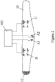
- Figure 2 is a plan view of the inside surface of a wide belt-like wrap 10 for fitting around the patient's midriff.
- the wrap 10 is wrapped around the patient's waist region with the electrodes on the inside, so that the electrodes A1, A2, B and C bear against the patient's skin at the appropriate locations on the patient's body. All or selected parts of the wrap may be elasticated so that the wrap is stretched around the region for snug fitting. Having areas of differing stretchability allows for a better fit.
- the wrap 10 is secured in place by Velcro hooks 12 at one end which engage a region of Velcro loops (not shown) at the other end.
- Wiring (not shown) to the electrodes is integrated into the wrap 10; techniques are known to do this.
- the electrodes may be pre-fixed to the wrap at manufacture, or they may be fixed by the user at pre-printed locations on the wrap. In the latter case the wiring for each electrode terminates in an exposed stud in the centre of the electrode area. Adhesive electrodes are then placed onto the wrap in the designated areas. One side of the electrode sticks to the inner surface of the wrap and the other bears against the skin when the wrap is worn.
- the wiring allows each electrode to be individually energised if desired.
- the printing of the electrode positions may be different for small/medium/large body sizes.
- the material of the wrap may be resiliently deformable, such as neoprene.
- the wrap may comprise an inelastic material in the electrode regions.
- the drive circuitry 100 is also schematically illustrated, and this may be constructed according to principles well-known in the NMES field.
- PCT/IB02/03309 discloses an electronic controller which can select electrodes from an array of electrodes to create current paths in the body.
- the current pulses applied to the electrodes are divided into two groups, the duration and intensity of which may be independently controlled.
- Group 1 pulses travel between electrodes B and C, Figure 3(a) , and may be thought of as stimulating primarily the abdominal muscles.
- the frequency of Group 1 pulses is 30 Hz.
- Successive Group 1 pulses travel alternately in opposite directions between the electrodes B and C, i.e. B->C, C->B, B->C, etc.
- Group 2 pulses travel between electrode A (segments A1 and A2 considered as a single electrode) and electrodes B and C alternately. Group 2 pulses are sub-divided into successive sets of four pulses. In each set the first two pulses are at 50% of the intensity of the last two pulses. In each set of four pulses the first pulse travels from electrode A to electrode B, the second pulse travels from electrode A to electrode C, the third pulse travels from electrode A to electrode B and the fourth pulse travels from electrode A to electrode C. Each Group 2 pulse follows the previous pulse after a 10ms delay. The frequency of the sets of four pulses is 20Hz, i.e., there are 80 discrete Group 2 pulses per second.
- the Group 1 and Group 2 pulses are not applied continuously to the electrodes. Rather, the pulses in each group are applied during successive therapy (contraction) periods alternating with relaxation periods where no pulses of that group are applied. Typically, the pulses of each group are applied cyclically with the following contraction-relaxation characteristics in each cycle:
- Group 1 pulses stabilise and support the trunk and mask the contraction of Group 2 pulses. For this reason it is preferred that the periods during which the Group 1 pulses are applied are at least temporally co-extensive with the periods during which the Group 2 pulses are applied. With the contraction-relaxation cycle shown above the support muscles of the trunk tend to start contracting appreciably first, due to the selected pulse parameters, frequencies and the neuroanatomy of the regbn.
- a balanced pulse and set-up may cause an imbalanced muscle contraction.
- a patient has a weakness in his right lower back (on the side of electrode segment A1). Similar current though electrode segments A1 and A2 may cause a stronger contraction in his left lower back, putting a skewing strain towards his left.
- pulses in Group 2 may be adjusted to give a more balanced contraction.
- the current through electrode segment A1 is set greater than through A2, Figure 3(c) . This may be due to pulses through segment A1 being of a longer pulse duration than through A2 and/or at a relatively higher intensity. Alternatively, current could be passed through only one of the segments A1, A2.
- Another example of using unbalanced pulses to give a balanced contraction is to reduce the truncal contractions in the region of electrode B, say, by spreading Group 1 pulses in the area of electrode B.
- Group 1 pulses normally travel between electrodes B and C.
- electrode C and electrodes B and A for a portion of the pulse period the relative contraction at B is reduced.
- the electrodes C and D are divided into two or more segments C1, C2, etc.
- Each segment is individually addressable (electrically energisable) so that separate current pathways, for example A1 to C1, A2 to C2, A1 to B2, etc, may be established. Since such segments C1, C2 are located at different angles with respect to electrode segments A1 and A2, the current path adjacent to the spine may be altered by energising different segments, or sets of segments, of electrodes A, B and C.
- the embodiments of the invention provide an apparatus for comfortably stimulating and effectively training and or re-educating the muscles of the lower back and abdomen. These muscles are important in both the prevention and treatment of back pain.
- the deep paraspinal fibres of multifidus muscle are thought to be particularly important and, until this invention, difficult to train.
- the effectiveness is based on the specific size, arrangement and anatomical location of the stimulating electrodes as well as the way in which pulses are passed between the electrodes to elicit targeted muscle contractions.
Landscapes
- Health & Medical Sciences (AREA)
- Life Sciences & Earth Sciences (AREA)
- Animal Behavior & Ethology (AREA)
- Nuclear Medicine, Radiotherapy & Molecular Imaging (AREA)
- Radiology & Medical Imaging (AREA)
- Biomedical Technology (AREA)
- Engineering & Computer Science (AREA)
- General Health & Medical Sciences (AREA)
- Public Health (AREA)
- Veterinary Medicine (AREA)
- Biophysics (AREA)
- Heart & Thoracic Surgery (AREA)
- Physical Education & Sports Medicine (AREA)
- Electrotherapy Devices (AREA)
Applications Claiming Priority (2)
| Application Number | Priority Date | Filing Date | Title |
|---|---|---|---|
| IES20090525 | 2009-07-10 | ||
| PCT/EP2010/058465 WO2011003709A1 (en) | 2009-07-10 | 2010-06-16 | Method and apparatus for stimulating the lower back and abdominal muscles |
Publications (2)
| Publication Number | Publication Date |
|---|---|
| EP2451525A1 EP2451525A1 (en) | 2012-05-16 |
| EP2451525B1 true EP2451525B1 (en) | 2019-06-12 |
Family
ID=42932021
Family Applications (1)
| Application Number | Title | Priority Date | Filing Date |
|---|---|---|---|
| EP10725182.9A Not-in-force EP2451525B1 (en) | 2009-07-10 | 2010-06-16 | Apparatus for stimulating the lower back and abdominal muscles |
Country Status (5)
| Country | Link |
|---|---|
| US (1) | US9675802B2 (zh) |
| EP (1) | EP2451525B1 (zh) |
| JP (2) | JP2012531990A (zh) |
| CN (1) | CN102470246B (zh) |
| WO (1) | WO2011003709A1 (zh) |
Families Citing this family (38)
| Publication number | Priority date | Publication date | Assignee | Title |
|---|---|---|---|---|
| US11679261B2 (en) | 2007-03-09 | 2023-06-20 | Mainstay Medical Limited | Systems and methods for enhancing function of spine stabilization muscles associated with a spine surgery intervention |
| US11331488B2 (en) | 2007-03-09 | 2022-05-17 | Mainstay Medical Limited | Systems and methods for enhancing function of spine stabilization muscles associated with a spine surgery intervention |
| US11679262B2 (en) | 2007-03-09 | 2023-06-20 | Mainstay Medical Limited | Systems and methods for restoring muscle function to the lumbar spine |
| US9072897B2 (en) | 2007-03-09 | 2015-07-07 | Mainstay Medical Limited | Systems and methods for restoring muscle function to the lumbar spine |
| WO2008112178A1 (en) | 2007-03-09 | 2008-09-18 | Dan Sachs | Muscle stimulator |
| US10925637B2 (en) * | 2010-03-11 | 2021-02-23 | Mainstay Medical Limited | Methods of implanting electrode leads for use with implantable neuromuscular electrical stimulator |
| JP2012531990A (ja) * | 2009-07-10 | 2012-12-13 | ユニバーシティ・カレッジ・ダブリン,ナショナル・ユニバーシティ・オブ・アイルランド,ダブリン | 腰部の筋肉及び腹筋を刺激するための方法及び装置 |
| WO2011026166A1 (en) | 2009-09-03 | 2011-03-10 | Murdoch Childrens Research Institute | Transcutaneous stimulation method and system |
| WO2011112773A2 (en) | 2010-03-11 | 2011-09-15 | Mainstay Medical, Inc. | Modular stimulator for treatment of back pain, implantable rf ablation system and methods of use |
| US11684774B2 (en) | 2010-03-11 | 2023-06-27 | Mainstay Medical Limited | Electrical stimulator for treatment of back pain and methods of use |
| WO2012116407A1 (en) | 2011-03-02 | 2012-09-07 | Murdoch Childrens Research Institute | Transcutaneous stimulation method and system |
| BR112013025521B1 (pt) | 2011-04-04 | 2021-04-13 | Micron Devices Llc | Condutor estimulador neural implantável sem fio |
| CA2843767C (en) | 2011-08-02 | 2019-07-09 | Mainstay Medical Limited | Apparatus for anchoring electrode leads for use with implantable neuromuscular electrical stimulator |
| EP3403690B1 (en) | 2011-09-15 | 2020-08-05 | Stimwave Technologies Incorporated | Relay module for implant |
| US9186501B2 (en) | 2012-06-13 | 2015-11-17 | Mainstay Medical Limited | Systems and methods for implanting electrode leads for use with implantable neuromuscular electrical stimulator |
| US11786725B2 (en) | 2012-06-13 | 2023-10-17 | Mainstay Medical Limited | Systems and methods for restoring muscle function to the lumbar spine and kits for implanting the same |
| US10195419B2 (en) | 2012-06-13 | 2019-02-05 | Mainstay Medical Limited | Electrode leads for use with implantable neuromuscular electrical stimulator |
| US9999763B2 (en) | 2012-06-13 | 2018-06-19 | Mainstay Medical Limited | Apparatus and methods for anchoring electrode leads adjacent to nervous tissue |
| US9950159B2 (en) | 2013-10-23 | 2018-04-24 | Mainstay Medical Limited | Systems and methods for restoring muscle function to the lumbar spine and kits for implanting the same |
| US9254393B2 (en) * | 2012-12-26 | 2016-02-09 | Micron Devices Llc | Wearable antenna assembly |
| WO2015051406A1 (en) | 2013-10-11 | 2015-04-16 | Gi Therapies Pty Ltd | Stimulation device and method for transcutaneous electrical stimulation |
| US10471268B2 (en) | 2014-10-16 | 2019-11-12 | Mainstay Medical Limited | Systems and methods for monitoring muscle rehabilitation |
| JP6308499B2 (ja) * | 2014-12-05 | 2018-04-11 | パナソニックIpマネジメント株式会社 | 電気刺激装置 |
| EP3263173A4 (en) | 2015-02-27 | 2019-02-20 | MTG Co., Ltd. | DEVICE FOR ELECTRIC MUSCLE STIMULATION |
| US9855005B2 (en) | 2015-04-22 | 2018-01-02 | Samsung Electronics Co., Ltd. | Wearable posture advisory system |
| JP2016202690A (ja) * | 2015-04-24 | 2016-12-08 | 株式会社 Mtg | 筋肉電気刺激装置 |
| WO2017125972A1 (ja) * | 2016-01-22 | 2017-07-27 | パナソニックIpマネジメント株式会社 | 電気刺激装置 |
| JP5976977B1 (ja) * | 2016-06-17 | 2016-08-24 | 株式会社 Mtg | 筋肉電気刺激装置 |
| US10327810B2 (en) | 2016-07-05 | 2019-06-25 | Mainstay Medical Limited | Systems and methods for enhanced implantation of electrode leads between tissue layers |
| CN106890057A (zh) * | 2017-03-14 | 2017-06-27 | 张妍妍 | 一种新型中西医结合诊疗床 |
| JP2018183480A (ja) * | 2017-04-27 | 2018-11-22 | 株式会社 Mtg | 筋肉電気刺激装置 |
| JP2021505332A (ja) | 2017-12-04 | 2021-02-18 | アトランティック セラピューティックス グループ リミテッドAtlantic Therapeutics Group Limited | 導電回路 |
| JP7302860B2 (ja) * | 2019-08-20 | 2023-07-04 | エーアイシルク株式会社 | 電気刺激装置 |
| EP3851158A4 (en) * | 2018-09-11 | 2022-06-08 | AI Silk Corporation | ELECTRIC STIMULATOR |
| JP2021108679A (ja) * | 2020-01-04 | 2021-08-02 | 株式会社Xenoma | 電気刺激衣類、電気刺激衣類用生地、電気刺激システム |
| US11925799B2 (en) * | 2020-03-13 | 2024-03-12 | Nicole Britta Cristiani | Muscle-stimulating athletic wear |
| US10932985B1 (en) * | 2020-03-14 | 2021-03-02 | Ryan Whelton | Systems and methods of positioning a body of a user during stimulation for therapeutic effects |
| US20230347136A1 (en) * | 2022-03-30 | 2023-11-02 | CyMedica Orthopedics, Inc. | Systems and methods for chronic lower back pain treatment |
Family Cites Families (40)
| Publication number | Priority date | Publication date | Assignee | Title |
|---|---|---|---|---|
| US2661744A (en) * | 1950-05-09 | 1953-12-08 | Relaxacizor Inc | Device for treatment of the muscles of the upper torso |
| US2842135A (en) * | 1956-11-26 | 1958-07-08 | Relaxacizor Inc | Electrical body treating device |
| US4326534A (en) * | 1979-06-21 | 1982-04-27 | Jens Axelgaard | Transcutaneous electrical muscle stimulation for treatment of scoliosis and other spinal deformities |
| US4432368A (en) * | 1980-09-24 | 1984-02-21 | Wallant International Trade, Inc. | Automatic electrode placement device |
| US4381012A (en) * | 1980-09-24 | 1983-04-26 | Wallant International Trade, Inc. | Electrode placement device |
| US4498480A (en) * | 1983-07-01 | 1985-02-12 | Mortensen John L | Adjustable probe belt assembly |
| GB8510832D0 (en) * | 1985-04-29 | 1985-06-05 | Bio Medical Res Ltd | Electrical stimulation of muscle |
| US4871439A (en) * | 1987-02-05 | 1989-10-03 | Steven Enzer | Disposable self-calibratable electrode package |
| CA1297952C (en) * | 1987-10-05 | 1992-03-24 | Diagnospine Research Inc. | Method and equipment for evaluating the flexibility of a human spine |
| CA1311275C (en) * | 1987-10-05 | 1992-12-08 | Serge Gracovetsky | Connection kit for skin-markers and electrodes |
| GB9211085D0 (en) * | 1992-05-23 | 1992-07-08 | Tippey Keith E | Electrical stimulation |
| ES2112307T3 (es) * | 1992-12-23 | 1998-04-01 | Vupiesse Italia Sas | Cinturon con un soporte para el ajuste de la posicion de los electrodos. |
| KR20010006395A (ko) * | 1997-04-15 | 2001-01-26 | 마이클 티. 퍼킨스 | 컴퓨터와 인터페이스 및 기타 장치가 통합된 지지 벨트 시스템 |
| US6065154A (en) * | 1998-04-07 | 2000-05-23 | Lifecor, Inc. | Support garments for patient-worn energy delivery apparatus |
| US6745062B1 (en) * | 1998-10-05 | 2004-06-01 | Advanced Imaging Systems, Inc. | Emg electrode apparatus and positioning system |
| GB2369998A (en) | 1999-01-11 | 2002-06-19 | Bmr Res & Dev Ltd | Abdominal muscle stimulation belt |
| EP1144045B1 (en) * | 1999-01-11 | 2003-05-21 | BMR Research and Development Limited | An electrotherapy device |
| US6546290B1 (en) * | 2000-04-12 | 2003-04-08 | Roamitron Holding S.A. | Method and apparatus for electromedical therapy |
| US20020077688A1 (en) * | 2000-12-15 | 2002-06-20 | Kirkland Thomas C. | Electrode-positioning body garment |
| EP2263743A1 (en) * | 2001-01-16 | 2010-12-22 | BMR Research & Development Limited | Apparatus for stimulating a muscle of a subject |
| EP1545700A4 (en) * | 2002-09-04 | 2006-09-27 | Univ Washington | METHOD OF TREATING CENTRAL NERVOUS SYSTEM DAMAGE |
| JP4500900B2 (ja) * | 2002-10-24 | 2010-07-14 | 小川 秀和 | 整復装置および衣類 |
| US20040215285A1 (en) * | 2003-04-22 | 2004-10-28 | Pollock Frederick William | Pain relief device |
| FI118753B (fi) * | 2003-10-03 | 2008-03-14 | Suunto Oy | Menetelmä sydämen lyöntien tunnistamiseksi ja siitä saatavien suureiden laskemiseksi |
| US7022093B2 (en) * | 2003-10-06 | 2006-04-04 | Thermodesigns, Inc. | Self-contained heating and cooling orthopaedic brace |
| DE102004009210A1 (de) * | 2004-02-25 | 2005-09-15 | Bauerfeind Ag | Elastische Bandage mit voneinander beabstandeten Elektroden |
| US7337005B2 (en) * | 2004-09-08 | 2008-02-26 | Spinal Modulations, Inc. | Methods for stimulating a nerve root ganglion |
| WO2006061805A2 (fr) | 2004-12-09 | 2006-06-15 | Compex Medical S.A. | Systeme d'electrodes pour stimulation transcutanee de nerfs et/ou de muscles |
| US20060161083A1 (en) * | 2005-01-15 | 2006-07-20 | Dunfee Matthew J | Ambulatory spinal unloading method and apparatus |
| EP1874398A4 (en) * | 2005-04-19 | 2008-08-20 | Compex Medical Sa | DEVICE FOR THE ADMINISTRATION OF ELECTRODE STIMULATION OF BACK AND BELLY MUSCLES |
| US20070049814A1 (en) * | 2005-08-24 | 2007-03-01 | Muccio Philip E | System and device for neuromuscular stimulation |
| US20080097530A1 (en) * | 2006-10-23 | 2008-04-24 | Muccio Philip | System for tissue stimulation and regeneration |
| DE102006058346A1 (de) * | 2006-12-11 | 2008-06-19 | Lohmann & Rauscher GmbH, Schönau | Vorrichtung zur transkutanen elektrischen Stimulation motorischer und/oder sensorischer Nerven |
| US7949403B2 (en) * | 2007-02-27 | 2011-05-24 | Accelerated Care Plus Corp. | Electrical stimulation device and method for the treatment of neurological disorders |
| CA2765891A1 (en) * | 2008-06-18 | 2009-12-23 | Accelerated Care Plus Corp. | Electrical stimulation method for reduction of joint compression |
| US9149386B2 (en) * | 2008-08-19 | 2015-10-06 | Niveus Medical, Inc. | Devices and systems for stimulation of tissues |
| WO2010080907A1 (en) * | 2009-01-07 | 2010-07-15 | Spiracur Inc. | Reduced pressure therapy of the sacral region |
| US8494658B2 (en) * | 2009-01-26 | 2013-07-23 | University College Dublin, National University Of Ireland, Dublin | Method and apparatus for stimulating pelvic floor muscles |
| JP2012531990A (ja) * | 2009-07-10 | 2012-12-13 | ユニバーシティ・カレッジ・ダブリン,ナショナル・ユニバーシティ・オブ・アイルランド,ダブリン | 腰部の筋肉及び腹筋を刺激するための方法及び装置 |
| US20120144551A1 (en) * | 2010-12-09 | 2012-06-14 | Eric Guldalian | Conductive Garment |
-
2010
- 2010-06-16 JP JP2012518863A patent/JP2012531990A/ja active Pending
- 2010-06-16 CN CN201080031160.2A patent/CN102470246B/zh not_active Expired - Fee Related
- 2010-06-16 WO PCT/EP2010/058465 patent/WO2011003709A1/en active Application Filing
- 2010-06-16 US US13/382,787 patent/US9675802B2/en active Active
- 2010-06-16 EP EP10725182.9A patent/EP2451525B1/en not_active Not-in-force
-
2015
- 2015-06-02 JP JP2015112483A patent/JP5973621B2/ja not_active Expired - Fee Related
Non-Patent Citations (1)
| Title |
|---|
| None * |
Also Published As
| Publication number | Publication date |
|---|---|
| JP5973621B2 (ja) | 2016-08-23 |
| EP2451525A1 (en) | 2012-05-16 |
| CN102470246B (zh) | 2015-08-05 |
| JP2012531990A (ja) | 2012-12-13 |
| WO2011003709A1 (en) | 2011-01-13 |
| JP2015186583A (ja) | 2015-10-29 |
| CN102470246A (zh) | 2012-05-23 |
| US9675802B2 (en) | 2017-06-13 |
| US20120116477A1 (en) | 2012-05-10 |
Similar Documents
| Publication | Publication Date | Title |
|---|---|---|
| EP2451525B1 (en) | Apparatus for stimulating the lower back and abdominal muscles | |
| US11141587B2 (en) | System, method, and apparatus for applying transcutaneous electrical stimulation | |
| US7725193B1 (en) | Intramuscular stimulation therapy using surface-applied localized electrical stimulation | |
| US6341237B1 (en) | Device for administrating electro-muscle stimulation and method of use | |
| RU2387467C1 (ru) | Способ коррекции мышечного дисбаланса у детей с нарушением осанки и сколиозом 1 и 2 степени | |
| US7844340B2 (en) | Devices and methods for transcutaneous electrical neural stimulation | |
| Tan et al. | Role of physical therapy in the treatment of cervical disk disease | |
| US20070049814A1 (en) | System and device for neuromuscular stimulation | |
| US20150032184A1 (en) | Neuromuscular stimulation system | |
| US10660820B2 (en) | Unit for action on biologically active body points and the relief of paravertebral muscles | |
| US20020077689A1 (en) | Electrode positioning bodysuit | |
| US20220347461A1 (en) | System, method, and apparatus for applying electrical stimulation | |
| TWI632931B (zh) | 一種高齡者復健健身穿戴裝置 | |
| RU168180U1 (ru) | Аппарат для воздействия на биоактивные точки организма и разгрузки паравертебральных мышц позвоночника | |
| Walsh | Transcutaneous electrical nerve stimulation and acupuncture points | |
| JP2008518689A (ja) | 運動増強内蔵型電気刺激装置および方法 | |
| RU168964U1 (ru) | Устройство для коррекции опорно-двигательного аппарата с микротоковой терапией | |
| TWI587799B (zh) | A postpartum rehabilitation electrode pants | |
| EP3228353B1 (en) | Unit for the correction of the supporting-locomotive apparatus by microcurrent therapy | |
| KR20220058298A (ko) | 스마트섬유 융합 선택적 전기자극 허리 보호대 | |
| RU2448744C1 (ru) | Способ коррекции фигуры | |
| CN208355926U (zh) | 作用于具有生物活性的体穴和缓解椎旁肌的装置 | |
| WO2023283461A2 (en) | Methods and apparatuses for rotational support | |
| KR20190035064A (ko) | 멀티 기능성 전기자극장치 | |
| MX2007005229A (en) | Exercise augmenting self-contained electro-stimulator and method |
Legal Events
| Date | Code | Title | Description |
|---|---|---|---|
| PUAI | Public reference made under article 153(3) epc to a published international application that has entered the european phase |
Free format text: ORIGINAL CODE: 0009012 |
|
| 17P | Request for examination filed |
Effective date: 20120210 |
|
| AK | Designated contracting states |
Kind code of ref document: A1 Designated state(s): AL AT BE BG CH CY CZ DE DK EE ES FI FR GB GR HR HU IE IS IT LI LT LU LV MC MK MT NL NO PL PT RO SE SI SK SM TR |
|
| DAX | Request for extension of the european patent (deleted) | ||
| STAA | Information on the status of an ep patent application or granted ep patent |
Free format text: STATUS: EXAMINATION IS IN PROGRESS |
|
| 17Q | First examination report despatched |
Effective date: 20171031 |
|
| 111Z | Information provided on other rights and legal means of execution |
Free format text: AL AT BE BG CH CY CZ DE DK EE ES FI FR GB GR HR HU IE IS IT LT LU LV MC MK MT NL NO PL PT RO SE SI SK SM TR Effective date: 20170915 |
|
| 17Q | First examination report despatched |
Effective date: 20180424 |
|
| GRAP | Despatch of communication of intention to grant a patent |
Free format text: ORIGINAL CODE: EPIDOSNIGR1 |
|
| STAA | Information on the status of an ep patent application or granted ep patent |
Free format text: STATUS: GRANT OF PATENT IS INTENDED |
|
| INTG | Intention to grant announced |
Effective date: 20190107 |
|
| GRAS | Grant fee paid |
Free format text: ORIGINAL CODE: EPIDOSNIGR3 |
|
| GRAA | (expected) grant |
Free format text: ORIGINAL CODE: 0009210 |
|
| STAA | Information on the status of an ep patent application or granted ep patent |
Free format text: STATUS: THE PATENT HAS BEEN GRANTED |
|
| AK | Designated contracting states |
Kind code of ref document: B1 Designated state(s): AL AT BE BG CH CY CZ DE DK EE ES FI FR GB GR HR HU IE IS IT LI LT LU LV MC MK MT NL NO PL PT RO SE SI SK SM TR |
|
| REG | Reference to a national code |
Ref country code: GB Ref legal event code: FG4D |
|
| REG | Reference to a national code |
Ref country code: CH Ref legal event code: EP |
|
| REG | Reference to a national code |
Ref country code: AT Ref legal event code: REF Ref document number: 1141807 Country of ref document: AT Kind code of ref document: T Effective date: 20190615 |
|
| REG | Reference to a national code |
Ref country code: DE Ref legal event code: R096 Ref document number: 602010059378 Country of ref document: DE |
|
| REG | Reference to a national code |
Ref country code: IE Ref legal event code: FG4D |
|
| REG | Reference to a national code |
Ref country code: NL Ref legal event code: MP Effective date: 20190612 |
|
| REG | Reference to a national code |
Ref country code: LT Ref legal event code: MG4D |
|
| PG25 | Lapsed in a contracting state [announced via postgrant information from national office to epo] |
Ref country code: FI Free format text: LAPSE BECAUSE OF FAILURE TO SUBMIT A TRANSLATION OF THE DESCRIPTION OR TO PAY THE FEE WITHIN THE PRESCRIBED TIME-LIMIT Effective date: 20190612 Ref country code: SE Free format text: LAPSE BECAUSE OF FAILURE TO SUBMIT A TRANSLATION OF THE DESCRIPTION OR TO PAY THE FEE WITHIN THE PRESCRIBED TIME-LIMIT Effective date: 20190612 Ref country code: HR Free format text: LAPSE BECAUSE OF FAILURE TO SUBMIT A TRANSLATION OF THE DESCRIPTION OR TO PAY THE FEE WITHIN THE PRESCRIBED TIME-LIMIT Effective date: 20190612 Ref country code: ES Free format text: LAPSE BECAUSE OF FAILURE TO SUBMIT A TRANSLATION OF THE DESCRIPTION OR TO PAY THE FEE WITHIN THE PRESCRIBED TIME-LIMIT Effective date: 20190612 Ref country code: LT Free format text: LAPSE BECAUSE OF FAILURE TO SUBMIT A TRANSLATION OF THE DESCRIPTION OR TO PAY THE FEE WITHIN THE PRESCRIBED TIME-LIMIT Effective date: 20190612 Ref country code: AL Free format text: LAPSE BECAUSE OF FAILURE TO SUBMIT A TRANSLATION OF THE DESCRIPTION OR TO PAY THE FEE WITHIN THE PRESCRIBED TIME-LIMIT Effective date: 20190612 Ref country code: NO Free format text: LAPSE BECAUSE OF FAILURE TO SUBMIT A TRANSLATION OF THE DESCRIPTION OR TO PAY THE FEE WITHIN THE PRESCRIBED TIME-LIMIT Effective date: 20190912 |
|
| PG25 | Lapsed in a contracting state [announced via postgrant information from national office to epo] |
Ref country code: LV Free format text: LAPSE BECAUSE OF FAILURE TO SUBMIT A TRANSLATION OF THE DESCRIPTION OR TO PAY THE FEE WITHIN THE PRESCRIBED TIME-LIMIT Effective date: 20190612 Ref country code: GR Free format text: LAPSE BECAUSE OF FAILURE TO SUBMIT A TRANSLATION OF THE DESCRIPTION OR TO PAY THE FEE WITHIN THE PRESCRIBED TIME-LIMIT Effective date: 20190913 Ref country code: BG Free format text: LAPSE BECAUSE OF FAILURE TO SUBMIT A TRANSLATION OF THE DESCRIPTION OR TO PAY THE FEE WITHIN THE PRESCRIBED TIME-LIMIT Effective date: 20190912 |
|
| REG | Reference to a national code |
Ref country code: AT Ref legal event code: MK05 Ref document number: 1141807 Country of ref document: AT Kind code of ref document: T Effective date: 20190612 |
|
| PG25 | Lapsed in a contracting state [announced via postgrant information from national office to epo] |
Ref country code: CZ Free format text: LAPSE BECAUSE OF FAILURE TO SUBMIT A TRANSLATION OF THE DESCRIPTION OR TO PAY THE FEE WITHIN THE PRESCRIBED TIME-LIMIT Effective date: 20190612 Ref country code: RO Free format text: LAPSE BECAUSE OF FAILURE TO SUBMIT A TRANSLATION OF THE DESCRIPTION OR TO PAY THE FEE WITHIN THE PRESCRIBED TIME-LIMIT Effective date: 20190612 Ref country code: PT Free format text: LAPSE BECAUSE OF FAILURE TO SUBMIT A TRANSLATION OF THE DESCRIPTION OR TO PAY THE FEE WITHIN THE PRESCRIBED TIME-LIMIT Effective date: 20191014 Ref country code: NL Free format text: LAPSE BECAUSE OF FAILURE TO SUBMIT A TRANSLATION OF THE DESCRIPTION OR TO PAY THE FEE WITHIN THE PRESCRIBED TIME-LIMIT Effective date: 20190612 Ref country code: EE Free format text: LAPSE BECAUSE OF FAILURE TO SUBMIT A TRANSLATION OF THE DESCRIPTION OR TO PAY THE FEE WITHIN THE PRESCRIBED TIME-LIMIT Effective date: 20190612 Ref country code: AT Free format text: LAPSE BECAUSE OF FAILURE TO SUBMIT A TRANSLATION OF THE DESCRIPTION OR TO PAY THE FEE WITHIN THE PRESCRIBED TIME-LIMIT Effective date: 20190612 Ref country code: SK Free format text: LAPSE BECAUSE OF FAILURE TO SUBMIT A TRANSLATION OF THE DESCRIPTION OR TO PAY THE FEE WITHIN THE PRESCRIBED TIME-LIMIT Effective date: 20190612 |
|
| REG | Reference to a national code |
Ref country code: CH Ref legal event code: PL |
|
| PG25 | Lapsed in a contracting state [announced via postgrant information from national office to epo] |
Ref country code: IT Free format text: LAPSE BECAUSE OF FAILURE TO SUBMIT A TRANSLATION OF THE DESCRIPTION OR TO PAY THE FEE WITHIN THE PRESCRIBED TIME-LIMIT Effective date: 20190612 Ref country code: SM Free format text: LAPSE BECAUSE OF FAILURE TO SUBMIT A TRANSLATION OF THE DESCRIPTION OR TO PAY THE FEE WITHIN THE PRESCRIBED TIME-LIMIT Effective date: 20190612 Ref country code: IS Free format text: LAPSE BECAUSE OF FAILURE TO SUBMIT A TRANSLATION OF THE DESCRIPTION OR TO PAY THE FEE WITHIN THE PRESCRIBED TIME-LIMIT Effective date: 20191012 |
|
| REG | Reference to a national code |
Ref country code: DE Ref legal event code: R097 Ref document number: 602010059378 Country of ref document: DE |
|
| REG | Reference to a national code |
Ref country code: BE Ref legal event code: MM Effective date: 20190630 |
|
| PG25 | Lapsed in a contracting state [announced via postgrant information from national office to epo] |
Ref country code: TR Free format text: LAPSE BECAUSE OF FAILURE TO SUBMIT A TRANSLATION OF THE DESCRIPTION OR TO PAY THE FEE WITHIN THE PRESCRIBED TIME-LIMIT Effective date: 20190612 Ref country code: MC Free format text: LAPSE BECAUSE OF FAILURE TO SUBMIT A TRANSLATION OF THE DESCRIPTION OR TO PAY THE FEE WITHIN THE PRESCRIBED TIME-LIMIT Effective date: 20190612 |
|
| PLBE | No opposition filed within time limit |
Free format text: ORIGINAL CODE: 0009261 |
|
| STAA | Information on the status of an ep patent application or granted ep patent |
Free format text: STATUS: NO OPPOSITION FILED WITHIN TIME LIMIT |
|
| PG25 | Lapsed in a contracting state [announced via postgrant information from national office to epo] |
Ref country code: DK Free format text: LAPSE BECAUSE OF FAILURE TO SUBMIT A TRANSLATION OF THE DESCRIPTION OR TO PAY THE FEE WITHIN THE PRESCRIBED TIME-LIMIT Effective date: 20190612 Ref country code: IE Free format text: LAPSE BECAUSE OF NON-PAYMENT OF DUE FEES Effective date: 20190616 Ref country code: PL Free format text: LAPSE BECAUSE OF FAILURE TO SUBMIT A TRANSLATION OF THE DESCRIPTION OR TO PAY THE FEE WITHIN THE PRESCRIBED TIME-LIMIT Effective date: 20190612 |
|
| 26N | No opposition filed |
Effective date: 20200313 |
|
| PG25 | Lapsed in a contracting state [announced via postgrant information from national office to epo] |
Ref country code: SI Free format text: LAPSE BECAUSE OF FAILURE TO SUBMIT A TRANSLATION OF THE DESCRIPTION OR TO PAY THE FEE WITHIN THE PRESCRIBED TIME-LIMIT Effective date: 20190612 Ref country code: LU Free format text: LAPSE BECAUSE OF NON-PAYMENT OF DUE FEES Effective date: 20190616 Ref country code: LI Free format text: LAPSE BECAUSE OF NON-PAYMENT OF DUE FEES Effective date: 20190630 Ref country code: BE Free format text: LAPSE BECAUSE OF NON-PAYMENT OF DUE FEES Effective date: 20190630 Ref country code: IS Free format text: LAPSE BECAUSE OF FAILURE TO SUBMIT A TRANSLATION OF THE DESCRIPTION OR TO PAY THE FEE WITHIN THE PRESCRIBED TIME-LIMIT Effective date: 20200224 Ref country code: CH Free format text: LAPSE BECAUSE OF NON-PAYMENT OF DUE FEES Effective date: 20190630 |
|
| PG2D | Information on lapse in contracting state deleted |
Ref country code: IS |
|
| PG25 | Lapsed in a contracting state [announced via postgrant information from national office to epo] |
Ref country code: CY Free format text: LAPSE BECAUSE OF FAILURE TO SUBMIT A TRANSLATION OF THE DESCRIPTION OR TO PAY THE FEE WITHIN THE PRESCRIBED TIME-LIMIT Effective date: 20190612 |
|
| PG25 | Lapsed in a contracting state [announced via postgrant information from national office to epo] |
Ref country code: HU Free format text: LAPSE BECAUSE OF FAILURE TO SUBMIT A TRANSLATION OF THE DESCRIPTION OR TO PAY THE FEE WITHIN THE PRESCRIBED TIME-LIMIT; INVALID AB INITIO Effective date: 20100616 Ref country code: MT Free format text: LAPSE BECAUSE OF FAILURE TO SUBMIT A TRANSLATION OF THE DESCRIPTION OR TO PAY THE FEE WITHIN THE PRESCRIBED TIME-LIMIT Effective date: 20190612 |
|
| PG25 | Lapsed in a contracting state [announced via postgrant information from national office to epo] |
Ref country code: MK Free format text: LAPSE BECAUSE OF FAILURE TO SUBMIT A TRANSLATION OF THE DESCRIPTION OR TO PAY THE FEE WITHIN THE PRESCRIBED TIME-LIMIT Effective date: 20190612 |
|
| PGFP | Annual fee paid to national office [announced via postgrant information from national office to epo] |
Ref country code: GB Payment date: 20221219 Year of fee payment: 13 Ref country code: FR Payment date: 20221220 Year of fee payment: 13 |
|
| PGFP | Annual fee paid to national office [announced via postgrant information from national office to epo] |
Ref country code: DE Payment date: 20221221 Year of fee payment: 13 |
|
| REG | Reference to a national code |
Ref country code: DE Ref legal event code: R119 Ref document number: 602010059378 Country of ref document: DE |
|
| GBPC | Gb: european patent ceased through non-payment of renewal fee |
Effective date: 20230616 |
|
| PG25 | Lapsed in a contracting state [announced via postgrant information from national office to epo] |
Ref country code: DE Free format text: LAPSE BECAUSE OF NON-PAYMENT OF DUE FEES Effective date: 20240103 Ref country code: GB Free format text: LAPSE BECAUSE OF NON-PAYMENT OF DUE FEES Effective date: 20230616 |
|
| PG25 | Lapsed in a contracting state [announced via postgrant information from national office to epo] |
Ref country code: FR Free format text: LAPSE BECAUSE OF NON-PAYMENT OF DUE FEES Effective date: 20230630 |