EP2450476A1 - Method for manufacturing aluminum foil - Google Patents
Method for manufacturing aluminum foil Download PDFInfo
- Publication number
- EP2450476A1 EP2450476A1 EP10794101A EP10794101A EP2450476A1 EP 2450476 A1 EP2450476 A1 EP 2450476A1 EP 10794101 A EP10794101 A EP 10794101A EP 10794101 A EP10794101 A EP 10794101A EP 2450476 A1 EP2450476 A1 EP 2450476A1
- Authority
- EP
- European Patent Office
- Prior art keywords
- aluminum foil
- aluminum
- plating solution
- substrate
- film
- Prior art date
- Legal status (The legal status is an assumption and is not a legal conclusion. Google has not performed a legal analysis and makes no representation as to the accuracy of the status listed.)
- Granted
Links
- 229910052782 aluminium Inorganic materials 0.000 title claims abstract description 175
- XAGFODPZIPBFFR-UHFFFAOYSA-N aluminium Chemical compound [Al] XAGFODPZIPBFFR-UHFFFAOYSA-N 0.000 title claims abstract description 164
- 239000011888 foil Substances 0.000 title claims abstract description 115
- 238000004519 manufacturing process Methods 0.000 title claims abstract description 34
- 238000000034 method Methods 0.000 title description 7
- 238000007747 plating Methods 0.000 claims abstract description 71
- 239000000758 substrate Substances 0.000 claims abstract description 37
- -1 aluminum halide Chemical class 0.000 claims abstract description 30
- 229910052801 chlorine Inorganic materials 0.000 claims abstract description 18
- 238000005868 electrolysis reaction Methods 0.000 claims abstract description 16
- 150000003457 sulfones Chemical class 0.000 claims abstract description 15
- 229910000039 hydrogen halide Inorganic materials 0.000 claims abstract description 12
- 239000012433 hydrogen halide Substances 0.000 claims abstract description 12
- 150000003839 salts Chemical class 0.000 claims abstract description 12
- 125000000217 alkyl group Chemical group 0.000 claims abstract description 7
- 150000003512 tertiary amines Chemical class 0.000 claims abstract description 6
- 125000001453 quaternary ammonium group Chemical group 0.000 claims abstract description 5
- 150000003242 quaternary ammonium salts Chemical class 0.000 claims abstract description 5
- 150000003141 primary amines Chemical class 0.000 claims abstract description 4
- 150000003335 secondary amines Chemical class 0.000 claims abstract description 4
- HHVIBTZHLRERCL-UHFFFAOYSA-N sulfonyldimethane Chemical group CS(C)(=O)=O HHVIBTZHLRERCL-UHFFFAOYSA-N 0.000 claims description 20
- 238000003860 storage Methods 0.000 claims description 17
- 229910052717 sulfur Inorganic materials 0.000 claims description 11
- 239000013078 crystal Substances 0.000 claims description 4
- 239000007772 electrode material Substances 0.000 claims description 2
- 239000000460 chlorine Substances 0.000 abstract description 20
- 230000015572 biosynthetic process Effects 0.000 abstract description 17
- ZAMOUSCENKQFHK-UHFFFAOYSA-N Chlorine atom Chemical compound [Cl] ZAMOUSCENKQFHK-UHFFFAOYSA-N 0.000 abstract description 8
- 239000000243 solution Substances 0.000 description 57
- 238000005096 rolling process Methods 0.000 description 17
- 239000005703 Trimethylamine hydrochloride Substances 0.000 description 12
- VSCWAEJMTAWNJL-UHFFFAOYSA-K aluminium trichloride Chemical compound Cl[Al](Cl)Cl VSCWAEJMTAWNJL-UHFFFAOYSA-K 0.000 description 12
- SZYJELPVAFJOGJ-UHFFFAOYSA-N trimethylamine hydrochloride Chemical compound Cl.CN(C)C SZYJELPVAFJOGJ-UHFFFAOYSA-N 0.000 description 12
- 239000003990 capacitor Substances 0.000 description 9
- 229910001220 stainless steel Inorganic materials 0.000 description 9
- 239000010935 stainless steel Substances 0.000 description 9
- 238000009713 electroplating Methods 0.000 description 8
- 238000012360 testing method Methods 0.000 description 8
- 238000002474 experimental method Methods 0.000 description 7
- UHOVQNZJYSORNB-UHFFFAOYSA-N Benzene Chemical compound C1=CC=CC=C1 UHOVQNZJYSORNB-UHFFFAOYSA-N 0.000 description 6
- HBBGRARXTFLTSG-UHFFFAOYSA-N Lithium ion Chemical compound [Li+] HBBGRARXTFLTSG-UHFFFAOYSA-N 0.000 description 6
- YXFVVABEGXRONW-UHFFFAOYSA-N Toluene Chemical compound CC1=CC=CC=C1 YXFVVABEGXRONW-UHFFFAOYSA-N 0.000 description 6
- XHFGWHUWQXTGAT-UHFFFAOYSA-N dimethylamine hydrochloride Natural products CNC(C)C XHFGWHUWQXTGAT-UHFFFAOYSA-N 0.000 description 6
- IQDGSYLLQPDQDV-UHFFFAOYSA-N dimethylazanium;chloride Chemical compound Cl.CNC IQDGSYLLQPDQDV-UHFFFAOYSA-N 0.000 description 6
- 229910001416 lithium ion Inorganic materials 0.000 description 6
- 239000000203 mixture Substances 0.000 description 6
- 230000003746 surface roughness Effects 0.000 description 6
- 239000003960 organic solvent Substances 0.000 description 5
- NLXLAEXVIDQMFP-UHFFFAOYSA-N Ammonia chloride Chemical compound [NH4+].[Cl-] NLXLAEXVIDQMFP-UHFFFAOYSA-N 0.000 description 4
- VEXZGXHMUGYJMC-UHFFFAOYSA-N Hydrochloric acid Chemical compound Cl VEXZGXHMUGYJMC-UHFFFAOYSA-N 0.000 description 4
- OKIZCWYLBDKLSU-UHFFFAOYSA-M N,N,N-Trimethylmethanaminium chloride Chemical compound [Cl-].C[N+](C)(C)C OKIZCWYLBDKLSU-UHFFFAOYSA-M 0.000 description 4
- PXHVJJICTQNCMI-UHFFFAOYSA-N Nickel Chemical compound [Ni] PXHVJJICTQNCMI-UHFFFAOYSA-N 0.000 description 4
- 230000007797 corrosion Effects 0.000 description 4
- 238000005260 corrosion Methods 0.000 description 4
- 230000000694 effects Effects 0.000 description 4
- 239000007789 gas Substances 0.000 description 4
- 229910000041 hydrogen chloride Inorganic materials 0.000 description 4
- IXCSERBJSXMMFS-UHFFFAOYSA-N hydrogen chloride Substances Cl.Cl IXCSERBJSXMMFS-UHFFFAOYSA-N 0.000 description 4
- 239000000463 material Substances 0.000 description 4
- 238000003756 stirring Methods 0.000 description 4
- 238000005406 washing Methods 0.000 description 4
- XLYOFNOQVPJJNP-UHFFFAOYSA-N water Substances O XLYOFNOQVPJJNP-UHFFFAOYSA-N 0.000 description 4
- 125000004169 (C1-C6) alkyl group Chemical group 0.000 description 3
- OKTJSMMVPCPJKN-UHFFFAOYSA-N Carbon Chemical compound [C] OKTJSMMVPCPJKN-UHFFFAOYSA-N 0.000 description 3
- ZMANZCXQSJIPKH-UHFFFAOYSA-N Triethylamine Chemical compound CCN(CC)CC ZMANZCXQSJIPKH-UHFFFAOYSA-N 0.000 description 3
- 229910052799 carbon Inorganic materials 0.000 description 3
- 150000001875 compounds Chemical class 0.000 description 3
- 238000002484 cyclic voltammetry Methods 0.000 description 3
- 239000008151 electrolyte solution Substances 0.000 description 3
- 238000011156 evaluation Methods 0.000 description 3
- CSCPPACGZOOCGX-UHFFFAOYSA-N Acetone Chemical compound CC(C)=O CSCPPACGZOOCGX-UHFFFAOYSA-N 0.000 description 2
- VEXZGXHMUGYJMC-UHFFFAOYSA-M Chloride anion Chemical compound [Cl-] VEXZGXHMUGYJMC-UHFFFAOYSA-M 0.000 description 2
- RYGMFSIKBFXOCR-UHFFFAOYSA-N Copper Chemical compound [Cu] RYGMFSIKBFXOCR-UHFFFAOYSA-N 0.000 description 2
- ROSDSFDQCJNGOL-UHFFFAOYSA-N Dimethylamine Chemical compound CNC ROSDSFDQCJNGOL-UHFFFAOYSA-N 0.000 description 2
- QUSNBJAOOMFDIB-UHFFFAOYSA-N Ethylamine Chemical compound CCN QUSNBJAOOMFDIB-UHFFFAOYSA-N 0.000 description 2
- YCKRFDGAMUMZLT-UHFFFAOYSA-N Fluorine atom Chemical compound [F] YCKRFDGAMUMZLT-UHFFFAOYSA-N 0.000 description 2
- 229910001290 LiPF6 Inorganic materials 0.000 description 2
- BAVYZALUXZFZLV-UHFFFAOYSA-N Methylamine Chemical compound NC BAVYZALUXZFZLV-UHFFFAOYSA-N 0.000 description 2
- 235000019270 ammonium chloride Nutrition 0.000 description 2
- 238000005516 engineering process Methods 0.000 description 2
- LIWAQLJGPBVORC-UHFFFAOYSA-N ethylmethylamine Chemical compound CCNC LIWAQLJGPBVORC-UHFFFAOYSA-N 0.000 description 2
- 229910052731 fluorine Inorganic materials 0.000 description 2
- 239000011737 fluorine Substances 0.000 description 2
- 239000010808 liquid waste Substances 0.000 description 2
- 230000008018 melting Effects 0.000 description 2
- 238000002844 melting Methods 0.000 description 2
- 229910052751 metal Inorganic materials 0.000 description 2
- 239000002184 metal Substances 0.000 description 2
- 229910052759 nickel Inorganic materials 0.000 description 2
- 239000007774 positive electrode material Substances 0.000 description 2
- WGYKZJWCGVVSQN-UHFFFAOYSA-N propylamine Chemical compound CCCN WGYKZJWCGVVSQN-UHFFFAOYSA-N 0.000 description 2
- 238000011160 research Methods 0.000 description 2
- GETQZCLCWQTVFV-UHFFFAOYSA-N trimethylamine Chemical compound CN(C)C GETQZCLCWQTVFV-UHFFFAOYSA-N 0.000 description 2
- MBDUIEKYVPVZJH-UHFFFAOYSA-N 1-ethylsulfonylethane Chemical compound CCS(=O)(=O)CC MBDUIEKYVPVZJH-UHFFFAOYSA-N 0.000 description 1
- BMVXCPBXGZKUPN-UHFFFAOYSA-N 1-hexanamine Chemical compound CCCCCCN BMVXCPBXGZKUPN-UHFFFAOYSA-N 0.000 description 1
- HBOOMWHZBIPTMN-UHFFFAOYSA-N 1-hexylsulfonylhexane Chemical compound CCCCCCS(=O)(=O)CCCCCC HBOOMWHZBIPTMN-UHFFFAOYSA-N 0.000 description 1
- YBJCDTIWNDBNTM-UHFFFAOYSA-N 1-methylsulfonylethane Chemical compound CCS(C)(=O)=O YBJCDTIWNDBNTM-UHFFFAOYSA-N 0.000 description 1
- JEXYCADTAFPULN-UHFFFAOYSA-N 1-propylsulfonylpropane Chemical compound CCCS(=O)(=O)CCC JEXYCADTAFPULN-UHFFFAOYSA-N 0.000 description 1
- CPELXLSAUQHCOX-UHFFFAOYSA-M Bromide Chemical compound [Br-] CPELXLSAUQHCOX-UHFFFAOYSA-M 0.000 description 1
- KMTRUDSVKNLOMY-UHFFFAOYSA-N Ethylene carbonate Chemical compound O=C1OCCO1 KMTRUDSVKNLOMY-UHFFFAOYSA-N 0.000 description 1
- 229910032387 LiCoO2 Inorganic materials 0.000 description 1
- WHXSMMKQMYFTQS-UHFFFAOYSA-N Lithium Chemical compound [Li] WHXSMMKQMYFTQS-UHFFFAOYSA-N 0.000 description 1
- NINIDFKCEFEMDL-UHFFFAOYSA-N Sulfur Chemical compound [S] NINIDFKCEFEMDL-UHFFFAOYSA-N 0.000 description 1
- RTAQQCXQSZGOHL-UHFFFAOYSA-N Titanium Chemical compound [Ti] RTAQQCXQSZGOHL-UHFFFAOYSA-N 0.000 description 1
- 239000011149 active material Substances 0.000 description 1
- 230000002411 adverse Effects 0.000 description 1
- SWLVFNYSXGMGBS-UHFFFAOYSA-N ammonium bromide Chemical compound [NH4+].[Br-] SWLVFNYSXGMGBS-UHFFFAOYSA-N 0.000 description 1
- QGZKDVFQNNGYKY-UHFFFAOYSA-O ammonium group Chemical group [NH4+] QGZKDVFQNNGYKY-UHFFFAOYSA-O 0.000 description 1
- 150000008064 anhydrides Chemical class 0.000 description 1
- 239000010953 base metal Substances 0.000 description 1
- 230000015556 catabolic process Effects 0.000 description 1
- 238000006243 chemical reaction Methods 0.000 description 1
- 230000000052 comparative effect Effects 0.000 description 1
- 239000004020 conductor Substances 0.000 description 1
- 229910052802 copper Inorganic materials 0.000 description 1
- 239000010949 copper Substances 0.000 description 1
- 239000011889 copper foil Substances 0.000 description 1
- 238000000354 decomposition reaction Methods 0.000 description 1
- 238000006731 degradation reaction Methods 0.000 description 1
- 230000008021 deposition Effects 0.000 description 1
- 238000011161 development Methods 0.000 description 1
- HPNMFZURTQLUMO-UHFFFAOYSA-N diethylamine Chemical compound CCNCC HPNMFZURTQLUMO-UHFFFAOYSA-N 0.000 description 1
- IEJIGPNLZYLLBP-UHFFFAOYSA-N dimethyl carbonate Chemical compound COC(=O)OC IEJIGPNLZYLLBP-UHFFFAOYSA-N 0.000 description 1
- WEHWNAOGRSTTBQ-UHFFFAOYSA-N dipropylamine Chemical compound CCCNCCC WEHWNAOGRSTTBQ-UHFFFAOYSA-N 0.000 description 1
- 239000003792 electrolyte Substances 0.000 description 1
- 125000001495 ethyl group Chemical group [H]C([H])([H])C([H])([H])* 0.000 description 1
- 229910002804 graphite Inorganic materials 0.000 description 1
- 239000010439 graphite Substances 0.000 description 1
- 125000004051 hexyl group Chemical group [H]C([H])([H])C([H])([H])C([H])([H])C([H])([H])C([H])([H])C([H])([H])* 0.000 description 1
- 231100000086 high toxicity Toxicity 0.000 description 1
- 238000009775 high-speed stirring Methods 0.000 description 1
- BICAGYDGRXJYGD-UHFFFAOYSA-N hydrobromide;hydrochloride Chemical compound Cl.Br BICAGYDGRXJYGD-UHFFFAOYSA-N 0.000 description 1
- 150000003840 hydrochlorides Chemical class 0.000 description 1
- 229910052739 hydrogen Inorganic materials 0.000 description 1
- 239000001257 hydrogen Substances 0.000 description 1
- 239000012535 impurity Substances 0.000 description 1
- 238000009776 industrial production Methods 0.000 description 1
- 230000005764 inhibitory process Effects 0.000 description 1
- XMBWDFGMSWQBCA-UHFFFAOYSA-M iodide Chemical compound [I-] XMBWDFGMSWQBCA-UHFFFAOYSA-M 0.000 description 1
- 229910052744 lithium Inorganic materials 0.000 description 1
- 229910000625 lithium cobalt oxide Inorganic materials 0.000 description 1
- BFZPBUKRYWOWDV-UHFFFAOYSA-N lithium;oxido(oxo)cobalt Chemical compound [Li+].[O-][Co]=O BFZPBUKRYWOWDV-UHFFFAOYSA-N 0.000 description 1
- 238000005259 measurement Methods 0.000 description 1
- 125000002496 methyl group Chemical group [H]C([H])([H])* 0.000 description 1
- 239000012046 mixed solvent Substances 0.000 description 1
- 239000007773 negative electrode material Substances 0.000 description 1
- QJGQUHMNIGDVPM-UHFFFAOYSA-N nitrogen group Chemical group [N] QJGQUHMNIGDVPM-UHFFFAOYSA-N 0.000 description 1
- 229910052760 oxygen Inorganic materials 0.000 description 1
- 229920000098 polyolefin Polymers 0.000 description 1
- 238000010248 power generation Methods 0.000 description 1
- 238000002360 preparation method Methods 0.000 description 1
- 238000012545 processing Methods 0.000 description 1
- 125000001436 propyl group Chemical group [H]C([*])([H])C([H])([H])C([H])([H])[H] 0.000 description 1
- 239000011593 sulfur Substances 0.000 description 1
- PUGUQINMNYINPK-UHFFFAOYSA-N tert-butyl 4-(2-chloroacetyl)piperazine-1-carboxylate Chemical compound CC(C)(C)OC(=O)N1CCN(C(=O)CCl)CC1 PUGUQINMNYINPK-UHFFFAOYSA-N 0.000 description 1
- DDFYFBUWEBINLX-UHFFFAOYSA-M tetramethylammonium bromide Chemical compound [Br-].C[N+](C)(C)C DDFYFBUWEBINLX-UHFFFAOYSA-M 0.000 description 1
- RXMRGBVLCSYIBO-UHFFFAOYSA-M tetramethylazanium;iodide Chemical compound [I-].C[N+](C)(C)C RXMRGBVLCSYIBO-UHFFFAOYSA-M 0.000 description 1
- 239000010936 titanium Substances 0.000 description 1
- 229910052719 titanium Inorganic materials 0.000 description 1
- YFTHZRPMJXBUME-UHFFFAOYSA-N tripropylamine Chemical compound CCCN(CCC)CCC YFTHZRPMJXBUME-UHFFFAOYSA-N 0.000 description 1
- 238000010792 warming Methods 0.000 description 1
- 238000004876 x-ray fluorescence Methods 0.000 description 1
Images

Classifications
-
- H—ELECTRICITY
- H01—ELECTRIC ELEMENTS
- H01M—PROCESSES OR MEANS, e.g. BATTERIES, FOR THE DIRECT CONVERSION OF CHEMICAL ENERGY INTO ELECTRICAL ENERGY
- H01M4/00—Electrodes
- H01M4/02—Electrodes composed of, or comprising, active material
- H01M4/64—Carriers or collectors
- H01M4/66—Selection of materials
- H01M4/661—Metal or alloys, e.g. alloy coatings
-
- C—CHEMISTRY; METALLURGY
- C25—ELECTROLYTIC OR ELECTROPHORETIC PROCESSES; APPARATUS THEREFOR
- C25D—PROCESSES FOR THE ELECTROLYTIC OR ELECTROPHORETIC PRODUCTION OF COATINGS; ELECTROFORMING; APPARATUS THEREFOR
- C25D1/00—Electroforming
- C25D1/04—Wires; Strips; Foils
-
- C—CHEMISTRY; METALLURGY
- C22—METALLURGY; FERROUS OR NON-FERROUS ALLOYS; TREATMENT OF ALLOYS OR NON-FERROUS METALS
- C22C—ALLOYS
- C22C21/00—Alloys based on aluminium
-
- C—CHEMISTRY; METALLURGY
- C25—ELECTROLYTIC OR ELECTROPHORETIC PROCESSES; APPARATUS THEREFOR
- C25D—PROCESSES FOR THE ELECTROLYTIC OR ELECTROPHORETIC PRODUCTION OF COATINGS; ELECTROFORMING; APPARATUS THEREFOR
- C25D3/00—Electroplating: Baths therefor
- C25D3/02—Electroplating: Baths therefor from solutions
- C25D3/42—Electroplating: Baths therefor from solutions of light metals
- C25D3/44—Aluminium
-
- C—CHEMISTRY; METALLURGY
- C25—ELECTROLYTIC OR ELECTROPHORETIC PROCESSES; APPARATUS THEREFOR
- C25D—PROCESSES FOR THE ELECTROLYTIC OR ELECTROPHORETIC PRODUCTION OF COATINGS; ELECTROFORMING; APPARATUS THEREFOR
- C25D3/00—Electroplating: Baths therefor
- C25D3/66—Electroplating: Baths therefor from melts
- C25D3/665—Electroplating: Baths therefor from melts from ionic liquids
-
- H—ELECTRICITY
- H01—ELECTRIC ELEMENTS
- H01G—CAPACITORS; CAPACITORS, RECTIFIERS, DETECTORS, SWITCHING DEVICES OR LIGHT-SENSITIVE DEVICES, OF THE ELECTROLYTIC TYPE
- H01G11/00—Hybrid capacitors, i.e. capacitors having different positive and negative electrodes; Electric double-layer [EDL] capacitors; Processes for the manufacture thereof or of parts thereof
- H01G11/22—Electrodes
- H01G11/26—Electrodes characterised by their structure, e.g. multi-layered, porosity or surface features
- H01G11/28—Electrodes characterised by their structure, e.g. multi-layered, porosity or surface features arranged or disposed on a current collector; Layers or phases between electrodes and current collectors, e.g. adhesives
-
- H—ELECTRICITY
- H01—ELECTRIC ELEMENTS
- H01G—CAPACITORS; CAPACITORS, RECTIFIERS, DETECTORS, SWITCHING DEVICES OR LIGHT-SENSITIVE DEVICES, OF THE ELECTROLYTIC TYPE
- H01G11/00—Hybrid capacitors, i.e. capacitors having different positive and negative electrodes; Electric double-layer [EDL] capacitors; Processes for the manufacture thereof or of parts thereof
- H01G11/66—Current collectors
- H01G11/68—Current collectors characterised by their material
-
- H—ELECTRICITY
- H01—ELECTRIC ELEMENTS
- H01G—CAPACITORS; CAPACITORS, RECTIFIERS, DETECTORS, SWITCHING DEVICES OR LIGHT-SENSITIVE DEVICES, OF THE ELECTROLYTIC TYPE
- H01G11/00—Hybrid capacitors, i.e. capacitors having different positive and negative electrodes; Electric double-layer [EDL] capacitors; Processes for the manufacture thereof or of parts thereof
- H01G11/74—Terminals, e.g. extensions of current collectors
-
- H—ELECTRICITY
- H01—ELECTRIC ELEMENTS
- H01G—CAPACITORS; CAPACITORS, RECTIFIERS, DETECTORS, SWITCHING DEVICES OR LIGHT-SENSITIVE DEVICES, OF THE ELECTROLYTIC TYPE
- H01G11/00—Hybrid capacitors, i.e. capacitors having different positive and negative electrodes; Electric double-layer [EDL] capacitors; Processes for the manufacture thereof or of parts thereof
- H01G11/84—Processes for the manufacture of hybrid or EDL capacitors, or components thereof
-
- H—ELECTRICITY
- H01—ELECTRIC ELEMENTS
- H01G—CAPACITORS; CAPACITORS, RECTIFIERS, DETECTORS, SWITCHING DEVICES OR LIGHT-SENSITIVE DEVICES, OF THE ELECTROLYTIC TYPE
- H01G9/00—Electrolytic capacitors, rectifiers, detectors, switching devices, light-sensitive or temperature-sensitive devices; Processes of their manufacture
- H01G9/16—Electrolytic capacitors, rectifiers, detectors, switching devices, light-sensitive or temperature-sensitive devices; Processes of their manufacture specially for use as rectifiers or detectors
-
- H—ELECTRICITY
- H01—ELECTRIC ELEMENTS
- H01M—PROCESSES OR MEANS, e.g. BATTERIES, FOR THE DIRECT CONVERSION OF CHEMICAL ENERGY INTO ELECTRICAL ENERGY
- H01M4/00—Electrodes
- H01M4/02—Electrodes composed of, or comprising, active material
- H01M4/64—Carriers or collectors
- H01M4/66—Selection of materials
-
- C—CHEMISTRY; METALLURGY
- C22—METALLURGY; FERROUS OR NON-FERROUS ALLOYS; TREATMENT OF ALLOYS OR NON-FERROUS METALS
- C22B—PRODUCTION AND REFINING OF METALS; PRETREATMENT OF RAW MATERIALS
- C22B21/00—Obtaining aluminium
- C22B21/0038—Obtaining aluminium by other processes
-
- H—ELECTRICITY
- H01—ELECTRIC ELEMENTS
- H01G—CAPACITORS; CAPACITORS, RECTIFIERS, DETECTORS, SWITCHING DEVICES OR LIGHT-SENSITIVE DEVICES, OF THE ELECTROLYTIC TYPE
- H01G11/00—Hybrid capacitors, i.e. capacitors having different positive and negative electrodes; Electric double-layer [EDL] capacitors; Processes for the manufacture thereof or of parts thereof
- H01G11/02—Hybrid capacitors, i.e. capacitors having different positive and negative electrodes; Electric double-layer [EDL] capacitors; Processes for the manufacture thereof or of parts thereof using combined reduction-oxidation reactions, e.g. redox arrangement or solion
-
- H—ELECTRICITY
- H01—ELECTRIC ELEMENTS
- H01G—CAPACITORS; CAPACITORS, RECTIFIERS, DETECTORS, SWITCHING DEVICES OR LIGHT-SENSITIVE DEVICES, OF THE ELECTROLYTIC TYPE
- H01G11/00—Hybrid capacitors, i.e. capacitors having different positive and negative electrodes; Electric double-layer [EDL] capacitors; Processes for the manufacture thereof or of parts thereof
- H01G11/04—Hybrid capacitors
-
- Y—GENERAL TAGGING OF NEW TECHNOLOGICAL DEVELOPMENTS; GENERAL TAGGING OF CROSS-SECTIONAL TECHNOLOGIES SPANNING OVER SEVERAL SECTIONS OF THE IPC; TECHNICAL SUBJECTS COVERED BY FORMER USPC CROSS-REFERENCE ART COLLECTIONS [XRACs] AND DIGESTS
- Y02—TECHNOLOGIES OR APPLICATIONS FOR MITIGATION OR ADAPTATION AGAINST CLIMATE CHANGE
- Y02E—REDUCTION OF GREENHOUSE GAS [GHG] EMISSIONS, RELATED TO ENERGY GENERATION, TRANSMISSION OR DISTRIBUTION
- Y02E60/00—Enabling technologies; Technologies with a potential or indirect contribution to GHG emissions mitigation
- Y02E60/10—Energy storage using batteries
-
- Y—GENERAL TAGGING OF NEW TECHNOLOGICAL DEVELOPMENTS; GENERAL TAGGING OF CROSS-SECTIONAL TECHNOLOGIES SPANNING OVER SEVERAL SECTIONS OF THE IPC; TECHNICAL SUBJECTS COVERED BY FORMER USPC CROSS-REFERENCE ART COLLECTIONS [XRACs] AND DIGESTS
- Y02—TECHNOLOGIES OR APPLICATIONS FOR MITIGATION OR ADAPTATION AGAINST CLIMATE CHANGE
- Y02E—REDUCTION OF GREENHOUSE GAS [GHG] EMISSIONS, RELATED TO ENERGY GENERATION, TRANSMISSION OR DISTRIBUTION
- Y02E60/00—Enabling technologies; Technologies with a potential or indirect contribution to GHG emissions mitigation
- Y02E60/13—Energy storage using capacitors
-
- Y—GENERAL TAGGING OF NEW TECHNOLOGICAL DEVELOPMENTS; GENERAL TAGGING OF CROSS-SECTIONAL TECHNOLOGIES SPANNING OVER SEVERAL SECTIONS OF THE IPC; TECHNICAL SUBJECTS COVERED BY FORMER USPC CROSS-REFERENCE ART COLLECTIONS [XRACs] AND DIGESTS
- Y10—TECHNICAL SUBJECTS COVERED BY FORMER USPC
- Y10T—TECHNICAL SUBJECTS COVERED BY FORMER US CLASSIFICATION
- Y10T428/00—Stock material or miscellaneous articles
- Y10T428/26—Web or sheet containing structurally defined element or component, the element or component having a specified physical dimension
- Y10T428/266—Web or sheet containing structurally defined element or component, the element or component having a specified physical dimension of base or substrate
Landscapes
- Engineering & Computer Science (AREA)
- Chemical & Material Sciences (AREA)
- Power Engineering (AREA)
- Materials Engineering (AREA)
- Organic Chemistry (AREA)
- Metallurgy (AREA)
- Electrochemistry (AREA)
- Chemical Kinetics & Catalysis (AREA)
- Microelectronics & Electronic Packaging (AREA)
- Mechanical Engineering (AREA)
- General Chemical & Material Sciences (AREA)
- Manufacturing & Machinery (AREA)
- Cell Electrode Carriers And Collectors (AREA)
- Electric Double-Layer Capacitors Or The Like (AREA)
- Electroplating And Plating Baths Therefor (AREA)
Abstract
Description
- The present invention relates to a method for producing an aluminum foil. More specifically, the present invention relates to a method for producing by electrolysis an aluminum foil that is usable, for example, as a positive electrode current collector for electrical storage devices such as lithium-ion secondary batteries and super capacitors (electrical double-layer capacitors, redox capacitors, lithium ion capacitors, etc.).
- It is a well known fact that lithium-ion secondary batteries, which have high energy density and show no significant decrease in discharge capacity, have been used to power sources for mobile tools, such as mobile phones and laptop computers. In recent years, with downsizing mobile tools, there is a need for smaller lithium-ion secondary batteries for use therein. Further, with the development of hybrid cars, solar power generation, and other technologies from the viewpoint of preventing global warming, etc., the application of super capacitors having high energy density, such as electrical double-layer capacitors, redox capacitors, and lithium ion capacitors, has been expanding at an accelerated pace, and there is a need for a further increase in energy density.
An electrical storage device, such as a lithium-ion secondary battery or a super capacitor, is configured, for example, such that a positive electrode, a negative electrode, and a separator made of polyolefine or the like between them are arranged in an organic electrolytic solution containing as an electrolyte a fluorine-containing compound, such as LiPF6 or NR4•BF4 (R is an alkyl group). The positive electrode comprises a positive electrode active material, such as LiCoO2 (lithium cobalt oxide) or active carbon, and a positive electrode current collector, while the negative electrode comprises a negative electrode active material, such as graphite or active carbon, and a negative electrode current collector. With respect to their shape, generally, a current collector having applied thereon an active material is formed into a sheet. The electrodes are each subjected to a large Voltage and also immersed in a highly corrosive organic electrolytic solution that contains a fluorine-containing compound. Accordingly, materials for a positive electrode current collector, in particular, are required to have excellent electrical conductivity together with excellent corrosion resistance. Under such circumstances, currently, nearly 100% of the time, the material for a positive electrode current collector is aluminum, which is a good electrical conductor and also forms a passive film on the surface to offer excellent corrosion resistance (as materials for a negative electrode current collector, copper, nickel, and the like can be mentioned). - One method for providing an electrical storage device with downsizing and higher energy density is thinning a sheet-shaped current collector that forms an electrode. Currently, an aluminum foil having a thickness of about 15 to 20 µm produced by rolling is commonly used as a positive electrode current collector. Therefore, the object can be achieved by further reducing the thickness of such an aluminum foil. However, in rolling, it is difficult to further reduce foil thickness on an industrial production scale.
Then, a possible aluminum foil production method to replace rolling is a method for producing an aluminum foil by electrolysis. The production of a metal foil by electrolysis is performed, for example, by forming a metal film on a surface of a substrate such as a stainless steel plate by electroplating, followed by the removal of the film from the substrate. Such production is well known as a method for producing a copper foil, for example. However, aluminum is an electrochemically base metal, and thus electroplating is extremely difficult. Therefore, it is not easy to produce an aluminum foil by electrolysis. Patent Document 1 discloses, as a method for producing an aluminum foil by electrolysis, a method that uses an electrolytic bath containing 50 to 75 mol% aluminum chloride and 25 to 50 mol% an alkylpyridinium chloride or an electrolytic bath prepared by adding an organic solvent to such a bath. However, in this method, the chlorine concentration in a plating solution is extremely high. This leads to problems in that during plating, chlorine contained in the plating solution reacts with moisture in the air to generate hydrogen chloride gas, causing the corrosion of equipment. Therefore, it is necessary to take a measure to prevent the generation of hydrogen chloride gas or a measure to protect equipment from corrosion due to the generated hydrogen chloride gas. Further, the method of Patent Document 1 also has problems in that the applicable current density is about 2 A/dm2 maximum, and thus the film formation rate is low (when the applied current density is increased any further, the plating solution decomposes, etc., making it impossible to stably perform plating). The addition of an organic solvent, such as benzene or toluene, to the plating solution is expected to improve the film formation rate. However, these organic solvents have high toxicity and are dangerous because of high inflammability, and, therefore, it must be said that the addition of such organic solvents to a plating solution is problematic in terms of the ease of liquid waste disposal and safety. -
- Patent Document 1:
JP-A-1-104791 - Thus, an object of the present invention is to provide a method for producing a high-ductility, high-purity aluminum foil at a high film formation rate by electrolysis using a plating solution having a low chlorine concentration.
- The present inventors have been intensively studying the aluminum electroplating technology. As a result of the research, they have developed a method that uses a plating solution prepared by dissolving an aluminum halide in a dialkyl sulfone (
JP-A-2008-31551 - A method for producing an aluminum foil of the present invention accomplished based on the above findings is, as defined in claim 1, characterized in that an aluminum film is formed on a surface of a substrate by electrolysis using a plating solution at least containing (1) a dialkyl sulfone, (2) an aluminum halide, and (3) at least one nitrogen-containing compound selected from the group consisting of an ammonium halide, a hydrogen halide salt of a primary amine, a hydrogen halide salt of a secondary amine, a hydrogen halide salt of a tertiary amine, and a quaternary ammonium salt represented by a general formula: R1R2R3R4N·X (wherein R1 to R4 independently represent an alkyl group and X represents a counteranion for the quaternary ammonium cation), and then the film is removed from the substrate.
A production method as defined inclaim 2 is characterized in that in the production method according to claim 1, the dialkyl sulfone is dimethyl sulfone.
An aluminum foil of the present invention is, as defined inclaim 3, characterized by having an aluminum content of 97.0 to 99.9 mass%, S and Cl contents of 1.5 mass% or less each, a Vickers hardness of 40 to 120 Hv, and a thickness of 1 to 15 µm.
An aluminum foil as defined inclaim 4 is characterized in that in the aluminum foil according toclaim 3, the aluminum foil has a cross-sectional configuration whose crystal structure increases in width from the surface of the aluminum foil that has been closer to a substrate towards the other surface.
Positive electrode current collector for an electrical storage device of the present invention is, as defined in claim 5, characterized by comprising an aluminum foil according toclaim 3.
An electrode for an electrical storage device of the present invention is, as defined inclaim 6, characterized by comprising an electrode active material supported on an aluminum foil according toclaim 3.
An electrical storage device of the present invention is, as defined in claim 7, characterized by being configured using an electrode for an electrical storage device according toclaim 6. - The present invention enables the provision of a method for producing a high-ductility, high-purity aluminum foil at a high film formation rate by electrolysis using a plating solution having a low chlorine concentration.
-
-
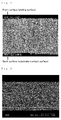
Fig. 1 is a cross-sectional photograph of an aluminum foil produced by a production method of the present invention in Experiment Example 4. - Similarly,
Fig. 2 is a cross-sectional photograph of an aluminum foil produced by rolling. -
Fig. 3 is a cyclic voltammogram for the case where an aluminum foil produced by a production method of the present invention is used as a test electrode in Application Example 1. - Similarly,
Fig. 4 is a cyclic voltammogram for the case where an aluminum foil produced by rolling is used as a test electrode. - A method for producing an aluminum foil of the present invention is characterized in that an aluminum film is formed on a surface of a substrate by electrolysis using a plating solution at least containing (1) a dialkyl sulfone, (2) an aluminum halide, and (3) at least one nitrogen-containing compound selected from the group consisting of an ammonium halide, a hydrogen halide salt of a primary amine, a hydrogen halide salt of a secondary amine, a hydrogen halide salt of a tertiary amine, and a quaternary ammonium salt represented by a general formula: R1R2R3R4N·X (wherein R1 to R4 independently represent an alkyl group and X represents a counteranion for the quaternary ammonium cation), and then the film is removed from the substrate.
- Examples of dialkyl sulfones to be contained in the plating solution used in the method for producing an aluminum foil of the present invention include those having a C1-6 alkyl group (straight or branched), such as dimethyl sulfone, diethyl sulfone, dipropyl sulfone, dihexyl sulfone, and methylethyl sulfone. In terms of excellent electrical conductivity, availability, and the like, it is preferable to use dimethyl sulfone.
- Examples of aluminum halides include aluminum chloride and aluminum bromide. In terms of minimizing the moisture content of the plating solution, which causes the inhibition of the deposition of aluminum, it is preferable to use an anhydride as the aluminum halide.
- Examples of ammonium halides usable as the nitrogen-containing compound include ammonium chloride and ammonium bromide. Further, examples of primary to tertiary amines include those having a C1-6 alkyl group (straight or branched), such as methylamine, dimethylamine, trimethylamine, ethylamine, diethylamine, triethylamine, propylamine, dipropylamine, tripropylamine, hexylamine, and methylethylamine. Examples of hydrogen halides include hydrogen chloride and hydrogen bromide. Examples of alkyl groups represented by R1 to R4 in a quaternary ammonium salt represented by a general formula: R1R2R3R4N·X (wherein R1 to R4 independently represent an alkyl group and X represents a counteranion for the quaternary ammonium cation) include C1-6 alkyl groups (straight or branched), such as a methyl group, an ethyl group, a propyl group, and a hexyl group. X may be a halide ion such as a chlorine ion, a bromine ion, or an iodine ion, or may alternatively be BF4 -, PF6 -, or the like, for example. Specific examples of such compounds include tetramethylammonium chloride, tetramethylammonium bromide, tetramethylammonium iodide, and tetraethylammonium tetrafluoroborate. In terms of facilitating the production of a high-ductility, high-purity aluminum foil at a high film formation rate, preferred examples of nitrogen-containing compounds include hydrochlorides of tertiary amines, such as trimethylamine hydrochloride.
- Dialkyl sulfone, aluminum halide, and nitrogen-containing compound are added in the following proportions, for example. Per 10 mol of dialkyl sulfone, the amount of aluminum halide is preferably 1.5 to 4.0 mol and more preferably 2.0 to 3.5 mol. The amount of nitrogen-containing compound is preferably 0.01 to 2.0 mol and more preferably 0. 05 to 1.5 mol. When the amount of aluminum halide added is less than 1.5 mol per 10 mol of dialkyl sulfone, this may cause the darkening of the formed aluminum film (a phenomenon called burning) or may reduce the film formation efficiency. Meanwhile, when it is more than 4. 0 mol, the solution resistance of the plating solution may become too high, whereby the plating solution is heated and decomposed. Further, when the amount of nitrogen-containing compound added is less than 0.01 mol per 10 mol of dialkyl sulfone, the addition is less likely to achieve its effects, that is, effects such as the improvement of the film formation rate owing to the achievement of plating at a high applied current density based on the improved electrical conductivity of the plating solution, the purity increase or ductility improvement in the aluminum foil, etc. Meanwhile, when it is more than 2. mol, because of an essential change in the composition of the plating solution, no aluminum may be deposited.
- The electroplating conditions may be, for example, conditions where the temperature of the plating solution is 80 to 110°C and the applied current density is 2 to 15 A/dm2. The lower limit of the plating solution temperature is to be determined in consideration of the melting point of the plating solution, and is preferably 85°C and more preferably 95°C (when the temperature is below the melting point of the plating solution, the plating solution solidifies, and plating cannot be performed anymore). Meanwhile, when the plating solution temperature is more than 110°C, this may accelerate the reaction between the aluminum film formed on the surface of the substrate and the plating solution, whereby more impurities are incorporated into the aluminum film, resulting in reduced purity. Further, when the applied current density is less than 2 A/dm2, the film formation efficiency may decrease, while when it is more than 15 A/dm2, because of the decomposition of the nitrogen-containing compound, etc., it may be impossible to stably perform plating or obtain a high-ductility, high-purity aluminum foil. The applied current density is preferably 3 to 12 A/dm2. A striking advantage of the plating solution used in the method for producing an aluminum foil of the present invention is that stable plating is possible even when a current density of 10 A/dm2 or more is applied, whereby the improvement of the film formation rate can be achieved. Incidentally, the plating time depends on the desired thickness of the aluminum foil, the temperature of the plating solution, the applied current density, and the like, and is usually 1 to 30 minutes. In terms of preventing the degradation of the plating solution to extend the life, it is preferable that the plating environment is a dry atmosphere.
- A substrate (cathode) for forming an aluminum film may be, for example, a stainless steel plate, a titanium plate, an aluminum plate, a nickel plate, or the like. Generally, in order to facilitate the removal of an aluminum film from a substrate, it is desired that the substrate has as smooth a surface as possible, such as a mirror-finished surface. However, the aluminum film formed on the surface of the substrate in the present invention is characterized by being easy to remove without subjecting the substrate to such processing (the reason therefor is not necessarily clear, but is presumably related to the following: upon the formation of an aluminum film on the surface of a substrate, the concentrations of S and Cl originated from the plating solution increase near the surface of the aluminum film that is in contact with the substrate). Incidentally, as a material for the anode, aluminum can be mentioned, for example. The aluminum film can be removed from the substrate batchwise. Alternatively, it is also possible to perform the formation and removal of an aluminum film continuously using a cathode drum (e.g.,
JP-A-6-93490 - According to the method for producing an aluminum foil of the present invention, an aluminum foil having a thickness of 15 µm or less, which has been extremely difficult to produce by rolling, and also an aluminum foil having a thickness of 10 µm or less, which, without exaggeration, has been almost impossible to produce by rolling, can be produced at a high film formation rate by electrolysis using a plating solution having a low chlorine concentration. In addition, the obtained aluminum foil is highly ductile and also highly pure. Specifically, according to the present invention, for example, an aluminum foil having an aluminum content of 97.0 to 99.9 mass%, S and Cl contents of 1.5 mass% or less each (normally 0.01 to 0.5 mass%), a Vickers hardness of 40 to 120 Hv, and a thickness of 1 to 15 µm (a small amount of inevitable C or O from the air may also be contained) can be easily produced with a surface roughness similar to the surface roughness of the substrate (e.g., when the Ra of the substrate is 1 to 10 µm, the Ra of the aluminum foil is about the same) . The produced aluminum foil can be used, for example, as a thinned positive electrode current collector for providing an electrical storage device with downsizing and higher energy density. The achievement of an aluminum foil having an Ra of about 1 to 10 µm corresponding to the Ra of a substrate is extremely advantageous in obtaining a positive electrode current collector required to have this level of surface roughness. Further, the plating solution used in the present invention does not require the addition of an organic solvent, such as benzene or toluene, for increasing the film formation rate, and thus offers an advantage in allowing washing with water and easy disposal of liquid waste.
- Hereinafter, the present invention will be described in detail with reference to the examples, but the following descriptions are not to be construed as restrictive.
- Dimethyl sulfone, anhydrous aluminum chloride, and trimethylamine hydrochloride were mixed in a molar ratio of 10:3:0.1 and dissolved at 110°C to give an electrolytic aluminum plating solution. Using an aluminum plate with a purity of 99.99% as the anode and a stainless steel plate having a surface roughness (Ra) of 5 µm as the cathode (substrate for forming an aluminum film), electroplating was performed at an applied current density of 3 A/dm2 for 10 minutes with stirring the plating solution and maintaining the plating solution at 95°C. Ten minutes later, the stainless steel plate having an aluminum film formed on the surface thereof was picked up from the plating solution, washed with water, and then dried. Subsequently, from the end portion thereof, forceps was inserted between the aluminum film and the stainless steel plate and moved to slide along the stainless steel plate. As a result, the aluminum film was easily removed from the stainless steel plate, and an aluminum foil was thus obtained. The obtained aluminum foil had a thickness of 5 µm, a surface roughness (Ra) of 5 µm, high aluminum purity (aluminum content: 99.9 mass%, S and Cl contents: 0.04 mass% each), and a Vickers hardness of 50 Hv (load: 0.05 kg). Thus, similarly to an aluminum foil produced by rolling, the aluminum foil was highly ductile. Incidentally, the thickness of the aluminum foil was measured by observing the cross section under a scanning electron microscope (S-800: manufactured by Hitachi, Ltd.) (the same applies hereinafter). The surface roughness (Ra) of the stainless steel plate used as the cathode and the aluminum foil was measured using an ultra-depth shape measuring microscope (VK-8510: manufactured by KEYENCE Corporation). The purity of the aluminum foil was measured as follows. After washing both sides of the aluminum foil with water, the S content was measured using a sulfur analyzer (EMIA-820W: manufactured by HORIBA, Ltd.), while the Cl content was measured using a wavelength-dispersive X-ray fluorescence spectrometer (RIX-2100: manufactured by Rigaku Corporation), and the remainder was defined as the aluminum content (the same applies hereinafter). The Vickers hardness of the aluminum foil was measured using a microhardness tester (MVK-E: manufactured by Akashi Seisakusho, Ltd.) (the same applies hereinafter).
- Dimethyl sulfone, anhydrous aluminum chloride, trimethylamine hydrochloride, and tetramethylammonium chloride were mixed in a molar ratio of 10:3:0.1:1 and dissolved at 110°C to give an electrolytic aluminum plating solution. Using the same anode and cathode as in Example 1, electroplating was performed at an applied current density of 12 A/dm2 with stirring the plating solution and maintaining the plating solution at 95°C. Incidentally, the stirring of the plating solution was performed at a higher speed than the stirring performed in Example 1, thereby preventing a decrease in the aluminum ion concentration near the cathode. As a result of the high-speed stirring of the plating solution containing tetramethylammonium chloride, stable electroplating was achieved at an applied current density higher than the applied current density in Example 1, and a 5 µm thick aluminum foil was obtained within a shorter period of time than in Example 1. Similarly to the aluminum foil obtained in Example 1, the obtained aluminum foil had high aluminum purity (aluminum content: 99.9 mass%, S and Cl contents: 0.04 mass% each) and a Vickers hardness of 80 Hv (load: 0.05 kg), together with high ductility.
- An aluminum foil was obtained in the same manner as in Example 1, except that ammonium chloride was used in place of trimethylamine hydrochloride. The obtained aluminum foil showed similar characteristics to the aluminum foil obtained in Example 1.
- An aluminum foil was obtained in the same manner as in Example 1, except that dimethylamine hydrochloride was used in place of trimethylamine hydrochloride. The obtained aluminum foil showed similar characteristics to the aluminum foil obtained in Example 1.
- An aluminum foil was obtained in the same manner as in Example 1, except that tetramethylammonium chloride was used in place of trimethylamine hydrochloride. The obtained aluminum foil showed similar characteristics to the aluminum foil obtained in Example 1.
- An aluminum foil was obtained in the same manner as in Example 1, except that tetraethylammonium tetrafluoroborate was used in place of trimethylamine hydrochloride. The obtained aluminum foil showed similar characteristics to the aluminum foil obtained in Example 1.
- Aluminum foils were obtained in the same manner as in Example 1, except that dimethyl sulfone, anhydrous aluminum chloride, and trimethylamine hydrochloride were mixed in a molar ratio of 10:3:0.01 or 0.03 and dissolved at 110°C to give an electrolytic aluminum plating solution. The purity of the aluminum foils was measured, and, together with the purity of the aluminum foil obtained in Example 1, the relation between the amount of trimethylamine hydrochloride added to an electrolytic aluminum plating solution and the purity of an aluminum foil was examined. Table 1 shows the results.
-
[Table 1] Amount of Trimethylamine Hydrochloride Added to Plating Solution (molar ratio to 10 mol of dimethyl sulfone) 0.01 0.03 0.1 (Example 1) Al Foil Composition (mass %) Al 99.5 99.8 99.9 S 0.2 0.1 0.04 Cl 0.3 0.1 0.04 - As is clear from Table 1, it was found that with an increase in the amount of trimethylamine hydrochloride added to an electrolytic aluminum plating solution, the purity of the resulting aluminum foil increases.
- Aluminum foils were obtained in the same manner as in Example 4, except that dimethyl sulfone, anhydrous aluminum chloride, and dimethylamine hydrochloride were mixed in a molar ratio of 10:3:0.01 or 0.03 and dissolved at 110°C to give an electrolytic aluminum plating solution. The purity of the aluminum foils was measured, and, together with the purity of the aluminum foil obtained in Example 4, the relation between the amount of dimethylamine hydrochloride added to an electrolytic aluminum plating solution and the purity of an aluminum foil was examined. Table 2 shows the results.
-
[Table 2] Amount of Dimethylamine Hydrochloride Added to Plating Solution (Molar ratio to 10 mol of dimethyl sulfone) 0.01 0.03 0.1 (Example 4) Al Foil Composition (mass %) Al 99.5 99.8 99.9 S 0.2 0.1 0.05 Cl 0.3 0.1 0.05 - As is clear from Table 2, it was found that with an increase in the amount of dimethylamine hydrochloride added to an electrolytic aluminum plating solution, the purity of the resulting aluminum foil increases.
- In the same manner as in Example 1 except that the applied current density was 5 A/dm2 and the plating time was varied to 10, 15, and 20 minutes, aluminum foils with thicknesses of 10, 15, and 20 µm, respectively, were obtained (each aluminum content: 99.9 mass%). The tensile strength of the obtained aluminum foils was measured according to JIS Z2241 using an autograph (EZ-Test: manufactured by Shimadzu Corporation). Table 3 shows the results. Further, Table 3 also shows the result of the measurement of the tensile strength of a commercially available, 20 µm thick aluminum foil produced by rolling (manufactured by Nippon Foil Mfg. Co., Ltd.).
-
[Table 3] Al Foil by Electrolysis
(Present Invention)Al Foil by Rolling
(Comparative Example)Thickness (µm) 10 15 20 20 Tensile Strength (N/mm2) 103.1 122.5 123.2 109.0 - As is clear from Table 3, it was found that the aluminum foils produced by the production method of the present invention have strength equal to or higher than the strength of the aluminum foil produced by rolling, and that in the case where the thickness is the same, the former has higher strength than the latter.
- The cross-sectional configuration of a 25 µm thick aluminum foil obtained in the same manner as in Example 1 except that the applied current density was 5 A/dm2 and the plating time was 25 minutes (aluminum content: 99.9 mass%) and the cross-sectional configuration of a commercially available, 20 µm thick aluminum foil produced by rolling (manufactured by Nippon Foil Mfg. Co., Ltd.) were observed under a scanning electron microscope (S-4300: manufactured by Hitachi Ltd.).
Fig. 1 and Fig. 2 show the results, respectively. As is clear fromFig. 1 , the aluminum foil produced by the production method of the present invention has a cross-sectional configuration whose crystal structure increases in width from the surface of the aluminum foil that has been closer to the substrate towards the other surface (widens towards the end), while, as is clear fromFig. 2 , the aluminum foil produced by rolling has a cross-sectional configuration whose crystal structure is elongated in the rolling direction and thus long sideways. It was thus found that the cross-sectional configurations of the two are completely different. - With respect to the aluminum foil obtained by removing the aluminum film from the stainless steel plate in Example 1, the composition near each surface was measured using an X-ray photoelectron spectrometer (ESCA-850M: manufactured by Shimadzu Corporation). As a result, the composition near the surface that had been closer to the substrate was different from the composition near the other surface, and an increase in the concentrations of S and Cl was found in the former, which was not found in the latter. Through a separate experiment, the present inventors have confirmed that in the case where there is a non-energization period before the start of electroplating, the longer the period is, the more the concentrations of S and Cl originated from the plating solution increase near the surface of the aluminum film that is in contact with the substrate, and a greater increase makes it easier to remove the aluminum film from the substrate. Accordingly, this led to the presumption that the reason why an aluminum film formed on the surface of a substrate in the present invention can be easily removed from the substrate is related to an increase in the concentrations of S and Cl near the surface of the aluminum film that is in contact with the substrate. Incidentally, the increase in the concentrations of S and Cl near the surface of the aluminum foil that has been closer to the substrate is cancelled by washing with water or washing using acetone, and thus does not have any adverse effect on the final quality of the aluminum foil (this means that there is an advantage in that after contributing to the removal of the aluminum film from the substrate, it can be washed away).
- Using a 15 µm thick aluminum foil obtained in the same manner as in Example 1 except that the applied current density was 5 A/dm2 and the plating time was 15 minutes (aluminum content: 99.9 mass%) as a test electrode and lithium foils as a counter electrode and a reference electrode, and also using a solution of LiPF6 dissolved in a mixed solvent of ethylene carbonate and dimethyl carbonate (volume ratio is 1:1) as an electrolytic solution, a three-electrode electrochemical evaluation cell was prepared. Using this electrochemical evaluation cell, the potential of the test electrode was scanned at a scanning rate of 1 mV/sec within a range of 1 to 6 V, and the characteristics were electrochemically evaluated by cyclic voltammetry.
Fig. 3 shows the results. Further,Fig. 4 shows the results of the same evaluation using a commercially available, 20 µm thick aluminum foil produced by rolling (manufactured by Nippon Foil Mfg. Co., Ltd.) as a test electrode. As is clear fromFig. 3 and Fig. 4 , similarly to the case where the aluminum foil produced by rolling was used as a test electrode, the current-potential curve stabilized from the second cycle also in the case where the aluminum foil produced by the production method of the present invention was used as a test electrode. Accordingly, the aluminum foil produced by the production method of the present invention was found to be applicable as a positive electrode current collector for an electrical storage device. - Using the aluminum foil obtained in Example 1 as a positive electrode current collector, a positive electrode active material was applied to the surface thereof, and the thus-obtained positive electrode was used to prepare an electrical storage device with a known configuration.
- The present invention makes it possible to provide a method for producing a high-ductility, high-purity aluminum foil at a high film formation rate by electrolysis using a plating solution having a low chlorine concentration. In this respect, the present invention is industrially applicable.
Claims (7)
- A method for producing an aluminum foil, characterized in that
an aluminum film is formed on a surface of a substrate by electrolysis using a plating solution at least containing (1) a dialkyl sulfone, (2) an aluminum halide, and (3) at least one nitrogen-containing compound selected from the group consisting of an ammonium halide, a hydrogen halide salt of a primary amine, a hydrogen halide salt of a secondary amine, a hydrogen halide salt of a tertiary amine, and a quaternary ammonium salt represented by a general formula: R1R2R3R4N·X (wherein R1 to R4 independently represent an alkyl group and X represents a counteranion for the quaternary ammonium cation), and
the film is then removed from the substrate. - A production method according to claim 1, characterized in that the dialkyl sulfone is dimethyl sulfone.
- An aluminum foil characterized by having an aluminum content of 97.0 to 99. 9 mass%, S and Cl contents of 1.5 mass% or less each, a Vickers hardness of 40 to 120 Hv, and a thickness of 1 to 15 µm.
- An aluminum foil according to claim 3, characterized by having a cross-sectional configuration whose crystal structure increases in width from the surface of the aluminum foil that has been closer to a substrate towards the other surface.
- Positive electrode current collector for an electrical storage device, characterized by comprising an aluminum foil according to claim 3.
- An electrode for an electrical storage device, characterized by comprising an electrode active material supported on an aluminum foil according to claim 3.
- An electrical storage device characterized by being configured using an electrode for an electrical storage device according to claim 6.
Applications Claiming Priority (2)
| Application Number | Priority Date | Filing Date | Title |
|---|---|---|---|
| JP2009153923 | 2009-06-29 | ||
| PCT/JP2010/060964 WO2011001932A1 (en) | 2009-06-29 | 2010-06-28 | Method for manufacturing aluminum foil |
Publications (3)
| Publication Number | Publication Date |
|---|---|
| EP2450476A1 true EP2450476A1 (en) | 2012-05-09 |
| EP2450476A4 EP2450476A4 (en) | 2014-01-22 |
| EP2450476B1 EP2450476B1 (en) | 2022-10-12 |
Family
ID=43411008
Family Applications (1)
| Application Number | Title | Priority Date | Filing Date |
|---|---|---|---|
| EP10794101.5A Active EP2450476B1 (en) | 2009-06-29 | 2010-06-28 | Method for manufacturing aluminum foil |
Country Status (6)
| Country | Link |
|---|---|
| US (1) | US9219279B2 (en) |
| EP (1) | EP2450476B1 (en) |
| JP (2) | JP5403053B2 (en) |
| KR (1) | KR101467643B1 (en) |
| CN (1) | CN102471909B (en) |
| WO (1) | WO2011001932A1 (en) |
Families Citing this family (17)
| Publication number | Priority date | Publication date | Assignee | Title |
|---|---|---|---|---|
| JPWO2012111585A1 (en) * | 2011-02-18 | 2014-07-07 | 住友電気工業株式会社 | Aluminum porous body and method for producing the same |
| JP5929000B2 (en) * | 2011-03-28 | 2016-06-01 | 日立金属株式会社 | Method for producing porous aluminum foil |
| JP5704456B2 (en) * | 2011-05-31 | 2015-04-22 | 日立金属株式会社 | Electrolytic aluminum foil production equipment |
| JP5737677B2 (en) * | 2011-07-19 | 2015-06-17 | 国立大学法人京都大学 | Method for producing porous aluminum material |
| WO2013062026A1 (en) | 2011-10-27 | 2013-05-02 | 日立金属株式会社 | Method for manufacturing porous aluminum foil, porous aluminum foil, positive electrode collector for electricity storage device, electrode for electricity storage device, and electricity storage device |
| CN104204308A (en) * | 2012-02-29 | 2014-12-10 | 日立金属株式会社 | Method for preparing low-melting-point plating solution for electrical aluminum plating, plating solution for electrical aluminum plating, method for producing aluminum foil, and method for lowering melting point of plating solution for electrical aluminum plating |
| KR20140148384A (en) * | 2012-03-22 | 2014-12-31 | 스미토모덴키고교가부시키가이샤 | Lithium secondary battery |
| JP6252832B2 (en) * | 2013-09-30 | 2017-12-27 | 日立金属株式会社 | Aluminum foil, electrode using the same, and power storage device |
| CN103730258A (en) * | 2014-01-08 | 2014-04-16 | 深圳顺络电子股份有限公司 | Positive pole mixed powder for producing positive pole of solid electrolytic capacitor |
| JP6427893B2 (en) * | 2014-02-20 | 2018-11-28 | 日立金属株式会社 | Electrolytic aluminum foil, current collector for power storage device, electrode for power storage device, power storage device |
| JP6318689B2 (en) | 2014-02-20 | 2018-05-09 | 日立金属株式会社 | Electrolytic aluminum foil and method for producing the same, current collector for power storage device, electrode for power storage device, power storage device |
| CN104213157A (en) * | 2014-09-17 | 2014-12-17 | 朱忠良 | Water-compatible electroplating molten aluminum, aluminum plating film forming method and formed aluminum plated article |
| JP2017084739A (en) * | 2015-10-30 | 2017-05-18 | 株式会社日本触媒 | Lithium ion secondary battery |
| JP7323022B2 (en) | 2018-02-14 | 2023-08-08 | 株式会社プロテリアル | Method for manufacturing aluminum foil |
| JP2019173164A (en) * | 2018-03-28 | 2019-10-10 | 日立金属株式会社 | Method of manufacturing aluminium foil |
| JP7247611B2 (en) * | 2019-01-31 | 2023-03-29 | 株式会社プロテリアル | Electrolytic aluminum foil with carrier foil |
| JP7293674B2 (en) * | 2019-01-31 | 2023-06-20 | 株式会社プロテリアル | bonding wire |
Citations (10)
| Publication number | Priority date | Publication date | Assignee | Title |
|---|---|---|---|---|
| JPH01104791A (en) * | 1987-10-17 | 1989-04-21 | Nisshin Steel Co Ltd | Production of electrolytic aluminum foil |
| JPH1197032A (en) * | 1997-09-18 | 1999-04-09 | Nippon Foil Mfg Co Ltd | Current collector made of aluminum foil for secondary cell |
| JP3054357B2 (en) * | 1996-02-08 | 2000-06-19 | 昭和アルミニウム株式会社 | Entry board for small diameter drilling |
| JP2002279999A (en) * | 2001-03-16 | 2002-09-27 | Sumitomo Metal Steel Products Inc | Metal foil for secondary battery collector, and method of manufacturing the same |
| US20050186477A1 (en) * | 2004-02-25 | 2005-08-25 | Jae-Yul Ryu | Current collector for a lithium secondary battery and a lithium secondary battery comprising the same |
| JP2006286381A (en) * | 2005-03-31 | 2006-10-19 | Sanyo Electric Co Ltd | Compression roll for manufacturing of electrode for battery, and manufacturing method of electrode for battery |
| JP2008012558A (en) * | 2006-07-05 | 2008-01-24 | Kobe Steel Ltd | Method of forming fine pattern and method of manufacturing metal sheet for formation of fine pattern |
| US20080067972A1 (en) * | 2006-09-15 | 2008-03-20 | Norio Takami | Power supply system and motor car |
| KR20080095993A (en) * | 2007-04-26 | 2008-10-30 | 주식회사 대유신소재 | Electroplating of aluminum on carbon fibers and carbon nanotubes |
| JP2010090414A (en) * | 2008-10-06 | 2010-04-22 | Hitachi Metals Ltd | Aluminum-electroplating solution, and plated aluminum film |
Family Cites Families (13)
| Publication number | Priority date | Publication date | Assignee | Title |
|---|---|---|---|---|
| US4849060A (en) * | 1986-12-04 | 1989-07-18 | Shell Internationale Research Maatschappij | Electrodeposition of aluminium from molten salt mixture |
| JPH01104792A (en) * | 1987-10-19 | 1989-04-21 | Nisshin Steel Co Ltd | Production of electrolytic fe-ni alloy foil |
| US5041194A (en) * | 1989-05-18 | 1991-08-20 | Mitsubishi Petrochemical Co., Ltd. | Aluminum electroplating method |
| JPH0693490A (en) | 1992-09-10 | 1994-04-05 | Nippon Denkai Kk | Manufacture of electrolytic metallic foil |
| JP2002184411A (en) | 2000-12-15 | 2002-06-28 | Sumitomo Electric Ind Ltd | Negative electrode collector for nonaqueous battery and its manufacturing method and negative electrode for nonaqueous battery |
| JP2004076031A (en) * | 2002-08-09 | 2004-03-11 | Ishikawajima Harima Heavy Ind Co Ltd | Plating bath for electroplating and plating bath for composite plating, and their production method |
| JP2005108724A (en) * | 2003-09-30 | 2005-04-21 | Sanyo Electric Co Ltd | Nonaqueous electrolyte secondary battery |
| JP2007070698A (en) * | 2005-09-07 | 2007-03-22 | Kyoto Univ | Method for electrodepositing metal |
| JP2007238980A (en) * | 2006-03-07 | 2007-09-20 | Hitachi Metals Ltd | Aluminum electroplating method and aluminum plated member |
| JP4986122B2 (en) * | 2006-03-31 | 2012-07-25 | 日立金属株式会社 | Electrolytic aluminum plating solution and aluminum plating film |
| JP4609777B2 (en) * | 2006-06-29 | 2011-01-12 | 日立金属株式会社 | Aluminum plating layer, metal member and manufacturing method thereof |
| JP5080097B2 (en) * | 2007-02-09 | 2012-11-21 | ディップソール株式会社 | Molten salt electroplating bath and plating method using the same |
| JP4530111B2 (en) * | 2008-10-15 | 2010-08-25 | 日立金属株式会社 | Electro-aluminum plating solution and method for forming aluminum plating film |
-
2010
- 2010-06-28 CN CN201080029194.8A patent/CN102471909B/en active Active
- 2010-06-28 EP EP10794101.5A patent/EP2450476B1/en active Active
- 2010-06-28 JP JP2011520907A patent/JP5403053B2/en active Active
- 2010-06-28 US US13/378,174 patent/US9219279B2/en active Active
- 2010-06-28 KR KR1020127002420A patent/KR101467643B1/en active IP Right Grant
- 2010-06-28 WO PCT/JP2010/060964 patent/WO2011001932A1/en active Application Filing
-
2013
- 2013-10-29 JP JP2013224353A patent/JP5979117B2/en active Active
Patent Citations (10)
| Publication number | Priority date | Publication date | Assignee | Title |
|---|---|---|---|---|
| JPH01104791A (en) * | 1987-10-17 | 1989-04-21 | Nisshin Steel Co Ltd | Production of electrolytic aluminum foil |
| JP3054357B2 (en) * | 1996-02-08 | 2000-06-19 | 昭和アルミニウム株式会社 | Entry board for small diameter drilling |
| JPH1197032A (en) * | 1997-09-18 | 1999-04-09 | Nippon Foil Mfg Co Ltd | Current collector made of aluminum foil for secondary cell |
| JP2002279999A (en) * | 2001-03-16 | 2002-09-27 | Sumitomo Metal Steel Products Inc | Metal foil for secondary battery collector, and method of manufacturing the same |
| US20050186477A1 (en) * | 2004-02-25 | 2005-08-25 | Jae-Yul Ryu | Current collector for a lithium secondary battery and a lithium secondary battery comprising the same |
| JP2006286381A (en) * | 2005-03-31 | 2006-10-19 | Sanyo Electric Co Ltd | Compression roll for manufacturing of electrode for battery, and manufacturing method of electrode for battery |
| JP2008012558A (en) * | 2006-07-05 | 2008-01-24 | Kobe Steel Ltd | Method of forming fine pattern and method of manufacturing metal sheet for formation of fine pattern |
| US20080067972A1 (en) * | 2006-09-15 | 2008-03-20 | Norio Takami | Power supply system and motor car |
| KR20080095993A (en) * | 2007-04-26 | 2008-10-30 | 주식회사 대유신소재 | Electroplating of aluminum on carbon fibers and carbon nanotubes |
| JP2010090414A (en) * | 2008-10-06 | 2010-04-22 | Hitachi Metals Ltd | Aluminum-electroplating solution, and plated aluminum film |
Non-Patent Citations (1)
| Title |
|---|
| See also references of WO2011001932A1 * |
Also Published As
| Publication number | Publication date |
|---|---|
| JP5403053B2 (en) | 2014-01-29 |
| JP2014051743A (en) | 2014-03-20 |
| WO2011001932A1 (en) | 2011-01-06 |
| KR20120101329A (en) | 2012-09-13 |
| KR101467643B1 (en) | 2014-12-01 |
| JPWO2011001932A1 (en) | 2012-12-13 |
| EP2450476B1 (en) | 2022-10-12 |
| CN102471909A (en) | 2012-05-23 |
| CN102471909B (en) | 2015-09-02 |
| JP5979117B2 (en) | 2016-08-24 |
| EP2450476A4 (en) | 2014-01-22 |
| US20120088153A1 (en) | 2012-04-12 |
| US9219279B2 (en) | 2015-12-22 |
Similar Documents
| Publication | Publication Date | Title |
|---|---|---|
| EP2450476B1 (en) | Method for manufacturing aluminum foil | |
| EP2639341B1 (en) | Method for producing aluminium foil | |
| US9812700B2 (en) | Method for producing porous aluminum foil, porous aluminum foil, positive electrode current collector for electrical storage devices, electrode for electrical storage devices, and electrical storage device | |
| US9514887B2 (en) | Aluminum foil with carbonaceous particles dispersed and supported therein | |
| Morita et al. | Anodic behavior of aluminum current collector in LiTFSI solutions with different solvent compositions | |
| KR102265234B1 (en) | Electrolytic aluminum foil, production method therefor, collector for power storage device, electrode for power storage device, and power storage device | |
| JP5617611B2 (en) | Composite metal foil with excellent tensile strength | |
| EP2821529B1 (en) | Method for electrical aluminum plating and method for producing aluminum foil | |
| JP5929000B2 (en) | Method for producing porous aluminum foil | |
| JP6252832B2 (en) | Aluminum foil, electrode using the same, and power storage device | |
| Peng et al. | Electrochemical behavior of aluminum foil in 1-alkyl-3-methylimidazolium tetrafluoroborate ionic liquids electrolytes |
Legal Events
| Date | Code | Title | Description |
|---|---|---|---|
| PUAI | Public reference made under article 153(3) epc to a published international application that has entered the european phase |
Free format text: ORIGINAL CODE: 0009012 |
|
| 17P | Request for examination filed |
Effective date: 20111220 |
|
| AK | Designated contracting states |
Kind code of ref document: A1 Designated state(s): AL AT BE BG CH CY CZ DE DK EE ES FI FR GB GR HR HU IE IS IT LI LT LU LV MC MK MT NL NO PL PT RO SE SI SK SM TR |
|
| DAX | Request for extension of the european patent (deleted) | ||
| A4 | Supplementary search report drawn up and despatched |
Effective date: 20140103 |
|
| RIC1 | Information provided on ipc code assigned before grant |
Ipc: C22B 21/00 20060101ALI20131218BHEP Ipc: H01G 9/008 20060101ALI20131218BHEP Ipc: H01G 11/68 20130101ALI20131218BHEP Ipc: H01G 11/28 20130101ALI20131218BHEP Ipc: H01G 11/84 20130101ALI20131218BHEP Ipc: C22C 21/00 20060101ALI20131218BHEP Ipc: C25D 1/00 20060101ALI20131218BHEP Ipc: H01M 4/66 20060101ALI20131218BHEP Ipc: C25D 3/66 20060101ALI20131218BHEP Ipc: C25D 3/44 20060101ALI20131218BHEP Ipc: H01G 11/02 20130101ALN20131218BHEP Ipc: H01G 11/04 20130101ALN20131218BHEP Ipc: C25D 1/04 20060101AFI20131218BHEP |
|
| STAA | Information on the status of an ep patent application or granted ep patent |
Free format text: STATUS: EXAMINATION IS IN PROGRESS |
|
| 17Q | First examination report despatched |
Effective date: 20170830 |
|
| STAA | Information on the status of an ep patent application or granted ep patent |
Free format text: STATUS: EXAMINATION IS IN PROGRESS |
|
| RIC1 | Information provided on ipc code assigned before grant |
Ipc: H01G 11/04 20130101ALN20201130BHEP Ipc: H01G 11/02 20130101ALN20201130BHEP Ipc: C22B 21/00 20060101ALI20201130BHEP Ipc: C25D 1/04 20060101AFI20201130BHEP Ipc: H01M 4/66 20060101ALI20201130BHEP Ipc: C25D 3/66 20060101ALI20201130BHEP Ipc: C25D 1/00 20060101ALI20201130BHEP Ipc: H01G 11/84 20130101ALI20201130BHEP Ipc: H01G 11/28 20130101ALI20201130BHEP Ipc: C25D 3/44 20060101ALI20201130BHEP Ipc: C22C 21/00 20060101ALI20201130BHEP Ipc: H01G 11/68 20130101ALI20201130BHEP Ipc: H01G 9/008 20060101ALI20201130BHEP |
|
| RIC1 | Information provided on ipc code assigned before grant |
Ipc: H01G 11/02 20130101ALN20201218BHEP Ipc: C25D 1/00 20060101ALI20201218BHEP Ipc: H01M 4/66 20060101ALI20201218BHEP Ipc: C25D 3/66 20060101ALI20201218BHEP Ipc: C25D 1/04 20060101AFI20201218BHEP Ipc: C25D 3/44 20060101ALI20201218BHEP Ipc: H01G 11/84 20130101ALI20201218BHEP Ipc: C22B 21/00 20060101ALI20201218BHEP Ipc: H01G 11/28 20130101ALI20201218BHEP Ipc: H01G 9/008 20060101ALI20201218BHEP Ipc: H01G 11/68 20130101ALI20201218BHEP Ipc: C22C 21/00 20060101ALI20201218BHEP Ipc: H01G 11/04 20130101ALN20201218BHEP |
|
| GRAP | Despatch of communication of intention to grant a patent |
Free format text: ORIGINAL CODE: EPIDOSNIGR1 |
|
| STAA | Information on the status of an ep patent application or granted ep patent |
Free format text: STATUS: GRANT OF PATENT IS INTENDED |
|
| RIC1 | Information provided on ipc code assigned before grant |
Ipc: C22C 21/00 20060101ALI20210115BHEP Ipc: H01G 11/68 20130101ALI20210115BHEP Ipc: C25D 1/00 20060101ALI20210115BHEP Ipc: H01G 11/28 20130101ALI20210115BHEP Ipc: H01G 11/04 20130101ALN20210115BHEP Ipc: H01G 9/008 20060101ALI20210115BHEP Ipc: C25D 3/66 20060101ALI20210115BHEP Ipc: H01G 11/02 20130101ALN20210115BHEP Ipc: H01G 11/84 20130101ALI20210115BHEP Ipc: C22B 21/00 20060101ALI20210115BHEP Ipc: H01M 4/66 20060101ALI20210115BHEP Ipc: C25D 1/04 20060101AFI20210115BHEP Ipc: C25D 3/44 20060101ALI20210115BHEP |
|
| INTG | Intention to grant announced |
Effective date: 20210204 |
|
| GRAJ | Information related to disapproval of communication of intention to grant by the applicant or resumption of examination proceedings by the epo deleted |
Free format text: ORIGINAL CODE: EPIDOSDIGR1 |
|
| STAA | Information on the status of an ep patent application or granted ep patent |
Free format text: STATUS: EXAMINATION IS IN PROGRESS |
|
| INTC | Intention to grant announced (deleted) | ||
| RIC1 | Information provided on ipc code assigned before grant |
Ipc: C25D 1/04 20060101AFI20210414BHEP Ipc: C22C 21/00 20060101ALI20210414BHEP Ipc: C25D 1/00 20060101ALI20210414BHEP Ipc: C25D 3/66 20060101ALI20210414BHEP Ipc: H01G 9/008 20060101ALI20210414BHEP Ipc: H01M 4/66 20060101ALI20210414BHEP Ipc: C25D 3/44 20060101ALI20210414BHEP Ipc: H01G 11/28 20130101ALI20210414BHEP Ipc: H01G 11/68 20130101ALI20210414BHEP Ipc: H01G 11/84 20130101ALI20210414BHEP Ipc: C22B 21/00 20060101ALI20210414BHEP Ipc: H01G 11/02 20130101ALN20210414BHEP Ipc: H01G 11/04 20130101ALN20210414BHEP |
|
| STAA | Information on the status of an ep patent application or granted ep patent |
Free format text: STATUS: EXAMINATION IS IN PROGRESS |
|
| GRAP | Despatch of communication of intention to grant a patent |
Free format text: ORIGINAL CODE: EPIDOSNIGR1 |
|
| STAA | Information on the status of an ep patent application or granted ep patent |
Free format text: STATUS: GRANT OF PATENT IS INTENDED |
|
| RIC1 | Information provided on ipc code assigned before grant |
Ipc: H01G 11/04 20130101ALN20220302BHEP Ipc: H01G 11/02 20130101ALN20220302BHEP Ipc: C22B 21/00 20060101ALI20220302BHEP Ipc: H01G 11/84 20130101ALI20220302BHEP Ipc: H01G 11/68 20130101ALI20220302BHEP Ipc: H01G 11/28 20130101ALI20220302BHEP Ipc: C25D 3/44 20060101ALI20220302BHEP Ipc: H01M 4/66 20060101ALI20220302BHEP Ipc: H01G 9/008 20060101ALI20220302BHEP Ipc: C25D 3/66 20060101ALI20220302BHEP Ipc: C25D 1/00 20060101ALI20220302BHEP Ipc: C22C 21/00 20060101ALI20220302BHEP Ipc: C25D 1/04 20060101AFI20220302BHEP |
|
| INTG | Intention to grant announced |
Effective date: 20220322 |
|
| GRAJ | Information related to disapproval of communication of intention to grant by the applicant or resumption of examination proceedings by the epo deleted |
Free format text: ORIGINAL CODE: EPIDOSDIGR1 |
|
| STAA | Information on the status of an ep patent application or granted ep patent |
Free format text: STATUS: EXAMINATION IS IN PROGRESS |
|
| INTC | Intention to grant announced (deleted) | ||
| RIC1 | Information provided on ipc code assigned before grant |
Ipc: H01G 11/04 20130101ALN20220530BHEP Ipc: H01G 11/02 20130101ALN20220530BHEP Ipc: C22B 21/00 20060101ALI20220530BHEP Ipc: H01G 11/84 20130101ALI20220530BHEP Ipc: H01G 11/68 20130101ALI20220530BHEP Ipc: H01G 11/28 20130101ALI20220530BHEP Ipc: C25D 3/44 20060101ALI20220530BHEP Ipc: H01M 4/66 20060101ALI20220530BHEP Ipc: H01G 9/008 20060101ALI20220530BHEP Ipc: C25D 3/66 20060101ALI20220530BHEP Ipc: C25D 1/00 20060101ALI20220530BHEP Ipc: C22C 21/00 20060101ALI20220530BHEP Ipc: C25D 1/04 20060101AFI20220530BHEP |
|
| GRAP | Despatch of communication of intention to grant a patent |
Free format text: ORIGINAL CODE: EPIDOSNIGR1 |
|
| STAA | Information on the status of an ep patent application or granted ep patent |
Free format text: STATUS: GRANT OF PATENT IS INTENDED |
|
| RIC1 | Information provided on ipc code assigned before grant |
Ipc: H01G 11/04 20130101ALN20220704BHEP Ipc: H01G 11/02 20130101ALN20220704BHEP Ipc: C22B 21/00 20060101ALI20220704BHEP Ipc: H01G 11/84 20130101ALI20220704BHEP Ipc: H01G 11/68 20130101ALI20220704BHEP Ipc: H01G 11/28 20130101ALI20220704BHEP Ipc: C25D 3/44 20060101ALI20220704BHEP Ipc: H01M 4/66 20060101ALI20220704BHEP Ipc: H01G 9/008 20060101ALI20220704BHEP Ipc: C25D 3/66 20060101ALI20220704BHEP Ipc: C25D 1/00 20060101ALI20220704BHEP Ipc: C22C 21/00 20060101ALI20220704BHEP Ipc: C25D 1/04 20060101AFI20220704BHEP |
|
| INTG | Intention to grant announced |
Effective date: 20220720 |
|
| GRAS | Grant fee paid |
Free format text: ORIGINAL CODE: EPIDOSNIGR3 |
|
| GRAA | (expected) grant |
Free format text: ORIGINAL CODE: 0009210 |
|
| STAA | Information on the status of an ep patent application or granted ep patent |
Free format text: STATUS: THE PATENT HAS BEEN GRANTED |
|
| AK | Designated contracting states |
Kind code of ref document: B1 Designated state(s): AL AT BE BG CH CY CZ DE DK EE ES FI FR GB GR HR HU IE IS IT LI LT LU LV MC MK MT NL NO PL PT RO SE SI SK SM TR |
|
| REG | Reference to a national code |
Ref country code: GB Ref legal event code: FG4D |
|
| REG | Reference to a national code |
Ref country code: CH Ref legal event code: EP |
|
| REG | Reference to a national code |
Ref country code: DE Ref legal event code: R096 Ref document number: 602010068517 Country of ref document: DE |
|
| REG | Reference to a national code |
Ref country code: IE Ref legal event code: FG4D |
|
| REG | Reference to a national code |
Ref country code: AT Ref legal event code: REF Ref document number: 1524213 Country of ref document: AT Kind code of ref document: T Effective date: 20221115 |
|
| REG | Reference to a national code |
Ref country code: LT Ref legal event code: MG9D |
|
| REG | Reference to a national code |
Ref country code: NL Ref legal event code: MP Effective date: 20221012 |
|
| REG | Reference to a national code |
Ref country code: AT Ref legal event code: MK05 Ref document number: 1524213 Country of ref document: AT Kind code of ref document: T Effective date: 20221012 |
|
| PG25 | Lapsed in a contracting state [announced via postgrant information from national office to epo] |
Ref country code: NL Free format text: LAPSE BECAUSE OF FAILURE TO SUBMIT A TRANSLATION OF THE DESCRIPTION OR TO PAY THE FEE WITHIN THE PRESCRIBED TIME-LIMIT Effective date: 20221012 |
|
| PG25 | Lapsed in a contracting state [announced via postgrant information from national office to epo] |
Ref country code: SE Free format text: LAPSE BECAUSE OF FAILURE TO SUBMIT A TRANSLATION OF THE DESCRIPTION OR TO PAY THE FEE WITHIN THE PRESCRIBED TIME-LIMIT Effective date: 20221012 Ref country code: PT Free format text: LAPSE BECAUSE OF FAILURE TO SUBMIT A TRANSLATION OF THE DESCRIPTION OR TO PAY THE FEE WITHIN THE PRESCRIBED TIME-LIMIT Effective date: 20230213 Ref country code: NO Free format text: LAPSE BECAUSE OF FAILURE TO SUBMIT A TRANSLATION OF THE DESCRIPTION OR TO PAY THE FEE WITHIN THE PRESCRIBED TIME-LIMIT Effective date: 20230112 Ref country code: LT Free format text: LAPSE BECAUSE OF FAILURE TO SUBMIT A TRANSLATION OF THE DESCRIPTION OR TO PAY THE FEE WITHIN THE PRESCRIBED TIME-LIMIT Effective date: 20221012 Ref country code: FI Free format text: LAPSE BECAUSE OF FAILURE TO SUBMIT A TRANSLATION OF THE DESCRIPTION OR TO PAY THE FEE WITHIN THE PRESCRIBED TIME-LIMIT Effective date: 20221012 Ref country code: ES Free format text: LAPSE BECAUSE OF FAILURE TO SUBMIT A TRANSLATION OF THE DESCRIPTION OR TO PAY THE FEE WITHIN THE PRESCRIBED TIME-LIMIT Effective date: 20221012 Ref country code: AT Free format text: LAPSE BECAUSE OF FAILURE TO SUBMIT A TRANSLATION OF THE DESCRIPTION OR TO PAY THE FEE WITHIN THE PRESCRIBED TIME-LIMIT Effective date: 20221012 |
|
| PG25 | Lapsed in a contracting state [announced via postgrant information from national office to epo] |
Ref country code: PL Free format text: LAPSE BECAUSE OF FAILURE TO SUBMIT A TRANSLATION OF THE DESCRIPTION OR TO PAY THE FEE WITHIN THE PRESCRIBED TIME-LIMIT Effective date: 20221012 Ref country code: LV Free format text: LAPSE BECAUSE OF FAILURE TO SUBMIT A TRANSLATION OF THE DESCRIPTION OR TO PAY THE FEE WITHIN THE PRESCRIBED TIME-LIMIT Effective date: 20221012 Ref country code: IS Free format text: LAPSE BECAUSE OF FAILURE TO SUBMIT A TRANSLATION OF THE DESCRIPTION OR TO PAY THE FEE WITHIN THE PRESCRIBED TIME-LIMIT Effective date: 20230212 Ref country code: HR Free format text: LAPSE BECAUSE OF FAILURE TO SUBMIT A TRANSLATION OF THE DESCRIPTION OR TO PAY THE FEE WITHIN THE PRESCRIBED TIME-LIMIT Effective date: 20221012 Ref country code: GR Free format text: LAPSE BECAUSE OF FAILURE TO SUBMIT A TRANSLATION OF THE DESCRIPTION OR TO PAY THE FEE WITHIN THE PRESCRIBED TIME-LIMIT Effective date: 20230113 |
|
| REG | Reference to a national code |
Ref country code: DE Ref legal event code: R097 Ref document number: 602010068517 Country of ref document: DE |
|
| PG25 | Lapsed in a contracting state [announced via postgrant information from national office to epo] |
Ref country code: SM Free format text: LAPSE BECAUSE OF FAILURE TO SUBMIT A TRANSLATION OF THE DESCRIPTION OR TO PAY THE FEE WITHIN THE PRESCRIBED TIME-LIMIT Effective date: 20221012 Ref country code: RO Free format text: LAPSE BECAUSE OF FAILURE TO SUBMIT A TRANSLATION OF THE DESCRIPTION OR TO PAY THE FEE WITHIN THE PRESCRIBED TIME-LIMIT Effective date: 20221012 Ref country code: EE Free format text: LAPSE BECAUSE OF FAILURE TO SUBMIT A TRANSLATION OF THE DESCRIPTION OR TO PAY THE FEE WITHIN THE PRESCRIBED TIME-LIMIT Effective date: 20221012 Ref country code: DK Free format text: LAPSE BECAUSE OF FAILURE TO SUBMIT A TRANSLATION OF THE DESCRIPTION OR TO PAY THE FEE WITHIN THE PRESCRIBED TIME-LIMIT Effective date: 20221012 Ref country code: CZ Free format text: LAPSE BECAUSE OF FAILURE TO SUBMIT A TRANSLATION OF THE DESCRIPTION OR TO PAY THE FEE WITHIN THE PRESCRIBED TIME-LIMIT Effective date: 20221012 |
|
| PGFP | Annual fee paid to national office [announced via postgrant information from national office to epo] |
Ref country code: DE Payment date: 20230502 Year of fee payment: 14 |
|
| PLBE | No opposition filed within time limit |
Free format text: ORIGINAL CODE: 0009261 |
|
| STAA | Information on the status of an ep patent application or granted ep patent |
Free format text: STATUS: NO OPPOSITION FILED WITHIN TIME LIMIT |
|
| PG25 | Lapsed in a contracting state [announced via postgrant information from national office to epo] |
Ref country code: SK Free format text: LAPSE BECAUSE OF FAILURE TO SUBMIT A TRANSLATION OF THE DESCRIPTION OR TO PAY THE FEE WITHIN THE PRESCRIBED TIME-LIMIT Effective date: 20221012 Ref country code: AL Free format text: LAPSE BECAUSE OF FAILURE TO SUBMIT A TRANSLATION OF THE DESCRIPTION OR TO PAY THE FEE WITHIN THE PRESCRIBED TIME-LIMIT Effective date: 20221012 |
|
| 26N | No opposition filed |
Effective date: 20230713 |
|
| PG25 | Lapsed in a contracting state [announced via postgrant information from national office to epo] |
Ref country code: SI Free format text: LAPSE BECAUSE OF FAILURE TO SUBMIT A TRANSLATION OF THE DESCRIPTION OR TO PAY THE FEE WITHIN THE PRESCRIBED TIME-LIMIT Effective date: 20221012 |
|
| PG25 | Lapsed in a contracting state [announced via postgrant information from national office to epo] |
Ref country code: MC Free format text: LAPSE BECAUSE OF FAILURE TO SUBMIT A TRANSLATION OF THE DESCRIPTION OR TO PAY THE FEE WITHIN THE PRESCRIBED TIME-LIMIT Effective date: 20221012 |
|
| PG25 | Lapsed in a contracting state [announced via postgrant information from national office to epo] |
Ref country code: MC Free format text: LAPSE BECAUSE OF FAILURE TO SUBMIT A TRANSLATION OF THE DESCRIPTION OR TO PAY THE FEE WITHIN THE PRESCRIBED TIME-LIMIT Effective date: 20221012 |
|
| REG | Reference to a national code |
Ref country code: CH Ref legal event code: PL |
|
| REG | Reference to a national code |
Ref country code: BE Ref legal event code: MM Effective date: 20230630 |
|
| GBPC | Gb: european patent ceased through non-payment of renewal fee |
Effective date: 20230628 |
|
| PG25 | Lapsed in a contracting state [announced via postgrant information from national office to epo] |
Ref country code: LU Free format text: LAPSE BECAUSE OF NON-PAYMENT OF DUE FEES Effective date: 20230628 |
|
| REG | Reference to a national code |
Ref country code: IE Ref legal event code: MM4A |
|
| PG25 | Lapsed in a contracting state [announced via postgrant information from national office to epo] |
Ref country code: LU Free format text: LAPSE BECAUSE OF NON-PAYMENT OF DUE FEES Effective date: 20230628 |
|
| PG25 | Lapsed in a contracting state [announced via postgrant information from national office to epo] |
Ref country code: IE Free format text: LAPSE BECAUSE OF NON-PAYMENT OF DUE FEES Effective date: 20230628 |
|
| PG25 | Lapsed in a contracting state [announced via postgrant information from national office to epo] |
Ref country code: IE Free format text: LAPSE BECAUSE OF NON-PAYMENT OF DUE FEES Effective date: 20230628 Ref country code: GB Free format text: LAPSE BECAUSE OF NON-PAYMENT OF DUE FEES Effective date: 20230628 Ref country code: CH Free format text: LAPSE BECAUSE OF NON-PAYMENT OF DUE FEES Effective date: 20230630 |