EP2450419A1 - Ferro-coke producing method and producing device - Google Patents
Ferro-coke producing method and producing device Download PDFInfo
- Publication number
- EP2450419A1 EP2450419A1 EP10808147A EP10808147A EP2450419A1 EP 2450419 A1 EP2450419 A1 EP 2450419A1 EP 10808147 A EP10808147 A EP 10808147A EP 10808147 A EP10808147 A EP 10808147A EP 2450419 A1 EP2450419 A1 EP 2450419A1
- Authority
- EP
- European Patent Office
- Prior art keywords
- gas
- furnace
- temperature
- carbonization
- iron composite
- Prior art date
- Legal status (The legal status is an assumption and is not a legal conclusion. Google has not performed a legal analysis and makes no representation as to the accuracy of the status listed.)
- Withdrawn
Links
- 239000000571 coke Substances 0.000 title description 45
- 238000000034 method Methods 0.000 title description 20
- 238000003763 carbonization Methods 0.000 claims abstract description 111
- 238000007664 blowing Methods 0.000 claims abstract description 106
- 239000002131 composite material Substances 0.000 claims abstract description 96
- QMQXDJATSGGYDR-UHFFFAOYSA-N methylidyneiron Chemical compound [C].[Fe] QMQXDJATSGGYDR-UHFFFAOYSA-N 0.000 claims abstract description 96
- XEEYBQQBJWHFJM-UHFFFAOYSA-N Iron Chemical compound [Fe] XEEYBQQBJWHFJM-UHFFFAOYSA-N 0.000 claims abstract description 67
- 239000002826 coolant Substances 0.000 claims abstract description 39
- 238000001816 cooling Methods 0.000 claims abstract description 37
- 229910052742 iron Inorganic materials 0.000 claims abstract description 33
- 239000000126 substance Substances 0.000 claims abstract description 23
- OKTJSMMVPCPJKN-UHFFFAOYSA-N Carbon Chemical compound [C] OKTJSMMVPCPJKN-UHFFFAOYSA-N 0.000 claims abstract description 12
- 229910052799 carbon Inorganic materials 0.000 claims abstract description 12
- 238000010000 carbonizing Methods 0.000 claims abstract description 11
- 238000007599 discharging Methods 0.000 claims abstract 2
- 238000004519 manufacturing process Methods 0.000 claims description 58
- 239000007789 gas Substances 0.000 description 143
- 230000009467 reduction Effects 0.000 description 19
- VYPSYNLAJGMNEJ-UHFFFAOYSA-N Silicium dioxide Chemical compound O=[Si]=O VYPSYNLAJGMNEJ-UHFFFAOYSA-N 0.000 description 12
- 239000003245 coal Substances 0.000 description 12
- 238000010438 heat treatment Methods 0.000 description 11
- 239000011449 brick Substances 0.000 description 7
- UQSXHKLRYXJYBZ-UHFFFAOYSA-N Iron oxide Chemical compound [Fe]=O UQSXHKLRYXJYBZ-UHFFFAOYSA-N 0.000 description 6
- JEIPFZHSYJVQDO-UHFFFAOYSA-N iron(III) oxide Inorganic materials O=[Fe]O[Fe]=O JEIPFZHSYJVQDO-UHFFFAOYSA-N 0.000 description 6
- 239000000377 silicon dioxide Substances 0.000 description 6
- 239000004575 stone Substances 0.000 description 5
- 238000004364 calculation method Methods 0.000 description 4
- 230000003247 decreasing effect Effects 0.000 description 4
- 230000008569 process Effects 0.000 description 4
- 238000006243 chemical reaction Methods 0.000 description 3
- 238000013461 design Methods 0.000 description 3
- 238000005265 energy consumption Methods 0.000 description 3
- 238000001465 metallisation Methods 0.000 description 3
- 239000000203 mixture Substances 0.000 description 3
- 230000009257 reactivity Effects 0.000 description 3
- 239000007787 solid Substances 0.000 description 3
- 238000012360 testing method Methods 0.000 description 3
- 230000003197 catalytic effect Effects 0.000 description 2
- 238000002485 combustion reaction Methods 0.000 description 2
- 230000000052 comparative effect Effects 0.000 description 2
- 239000000446 fuel Substances 0.000 description 2
- 239000000463 material Substances 0.000 description 2
- 238000002156 mixing Methods 0.000 description 2
- XLYOFNOQVPJJNP-UHFFFAOYSA-N water Substances O XLYOFNOQVPJJNP-UHFFFAOYSA-N 0.000 description 2
- 239000003575 carbonaceous material Substances 0.000 description 1
- 238000007796 conventional method Methods 0.000 description 1
- 230000000694 effects Effects 0.000 description 1
- 238000004134 energy conservation Methods 0.000 description 1
- 238000005516 engineering process Methods 0.000 description 1
- 238000002474 experimental method Methods 0.000 description 1
- 229910052840 fayalite Inorganic materials 0.000 description 1
- 239000012634 fragment Substances 0.000 description 1
- 238000012986 modification Methods 0.000 description 1
- 230000004048 modification Effects 0.000 description 1
- 239000002245 particle Substances 0.000 description 1
- 230000035699 permeability Effects 0.000 description 1
- 239000000843 powder Substances 0.000 description 1
- 239000002994 raw material Substances 0.000 description 1
- 238000010405 reoxidation reaction Methods 0.000 description 1
- 238000004088 simulation Methods 0.000 description 1
Images


Classifications
-
- C—CHEMISTRY; METALLURGY
- C10—PETROLEUM, GAS OR COKE INDUSTRIES; TECHNICAL GASES CONTAINING CARBON MONOXIDE; FUELS; LUBRICANTS; PEAT
- C10B—DESTRUCTIVE DISTILLATION OF CARBONACEOUS MATERIALS FOR PRODUCTION OF GAS, COKE, TAR, OR SIMILAR MATERIALS
- C10B3/00—Coke ovens with vertical chambers
-
- C—CHEMISTRY; METALLURGY
- C10—PETROLEUM, GAS OR COKE INDUSTRIES; TECHNICAL GASES CONTAINING CARBON MONOXIDE; FUELS; LUBRICANTS; PEAT
- C10B—DESTRUCTIVE DISTILLATION OF CARBONACEOUS MATERIALS FOR PRODUCTION OF GAS, COKE, TAR, OR SIMILAR MATERIALS
- C10B47/00—Destructive distillation of solid carbonaceous materials with indirect heating, e.g. by external combustion
- C10B47/18—Destructive distillation of solid carbonaceous materials with indirect heating, e.g. by external combustion with moving charge
- C10B47/20—Destructive distillation of solid carbonaceous materials with indirect heating, e.g. by external combustion with moving charge according to the moving bed type
-
- C—CHEMISTRY; METALLURGY
- C10—PETROLEUM, GAS OR COKE INDUSTRIES; TECHNICAL GASES CONTAINING CARBON MONOXIDE; FUELS; LUBRICANTS; PEAT
- C10B—DESTRUCTIVE DISTILLATION OF CARBONACEOUS MATERIALS FOR PRODUCTION OF GAS, COKE, TAR, OR SIMILAR MATERIALS
- C10B49/00—Destructive distillation of solid carbonaceous materials by direct heating with heat-carrying agents including the partial combustion of the solid material to be treated
- C10B49/02—Destructive distillation of solid carbonaceous materials by direct heating with heat-carrying agents including the partial combustion of the solid material to be treated with hot gases or vapours, e.g. hot gases obtained by partial combustion of the charge
- C10B49/04—Destructive distillation of solid carbonaceous materials by direct heating with heat-carrying agents including the partial combustion of the solid material to be treated with hot gases or vapours, e.g. hot gases obtained by partial combustion of the charge while moving the solid material to be treated
- C10B49/06—Destructive distillation of solid carbonaceous materials by direct heating with heat-carrying agents including the partial combustion of the solid material to be treated with hot gases or vapours, e.g. hot gases obtained by partial combustion of the charge while moving the solid material to be treated according to the moving bed type
-
- C—CHEMISTRY; METALLURGY
- C10—PETROLEUM, GAS OR COKE INDUSTRIES; TECHNICAL GASES CONTAINING CARBON MONOXIDE; FUELS; LUBRICANTS; PEAT
- C10B—DESTRUCTIVE DISTILLATION OF CARBONACEOUS MATERIALS FOR PRODUCTION OF GAS, COKE, TAR, OR SIMILAR MATERIALS
- C10B53/00—Destructive distillation, specially adapted for particular solid raw materials or solid raw materials in special form
- C10B53/08—Destructive distillation, specially adapted for particular solid raw materials or solid raw materials in special form in the form of briquettes, lumps and the like
-
- C—CHEMISTRY; METALLURGY
- C10—PETROLEUM, GAS OR COKE INDUSTRIES; TECHNICAL GASES CONTAINING CARBON MONOXIDE; FUELS; LUBRICANTS; PEAT
- C10B—DESTRUCTIVE DISTILLATION OF CARBONACEOUS MATERIALS FOR PRODUCTION OF GAS, COKE, TAR, OR SIMILAR MATERIALS
- C10B57/00—Other carbonising or coking processes; Features of destructive distillation processes in general
- C10B57/04—Other carbonising or coking processes; Features of destructive distillation processes in general using charges of special composition
- C10B57/06—Other carbonising or coking processes; Features of destructive distillation processes in general using charges of special composition containing additives
Definitions
- the present invention relates to a method and an apparatus for producing carbon iron composite (ferrocoke) in which a formed product of a carbon-containing substance and an iron-containing substance is continuously carbonized in a vertical carbonization furnace to produce metallic iron in coke.
- Metallurgical coke which is produced by coal carbonized in a coke oven, is generally used in the operation of a blast furnace.
- a technique for using metallurgical carbon iron composite which is produced by carbonizing a mixture of coal and iron ore, in the operation of a blast furnace.
- Carbon iron composite can increase the CO 2 reactivity of coke in the carbon iron composite by the catalytic effect of reduced iron ore and can decrease the percentage of a reducing material as a result of a decrease in thermal reserve zone temperature.
- a method for continuously producing formed coke As a substitute for a method for producing coke in a chamber oven, a method for continuously producing formed coke has been developed.
- a vertical shaft furnace constructed of chamotte bricks in place of silica stone bricks is used as a carbonization furnace.
- Coal is cold-formed in a predetermined size and is fed into a vertical shaft furnace.
- the briquettes are carbonized by heating with a circulating heating gas to produce formed coke. It has been demonstrated that coke having a strength comparable to that of coke produced with a conventional coke oven can be produced even by using a large amount of naturally abundant and inexpensive non- or slightly-caking coal.
- One known method for continuously producing formed coke is characterized in that a top gas of a vertical carbonization furnace is utilized as a coolant gas into a lower portion of a cooling chamber directly coupled to a carbonization chamber of the vertical carbonization furnace, and most of the gas passing through the cooling chamber is exhausted from an upper portion of the cooling chamber and is supplied as a heating gas to an inlet in an intermediate portion of the carbonization furnace (see, for example, Patent Document 1).
- This method requires three gas inlets (an intermediate portion of the carbonization chamber, a lower portion of the carbonization chamber, and a lower portion of the cooling chamber) and one gas outlet (an upper portion of the cooling chamber), which makes the equipment complicated.
- Sensible heat generated by the cooling of high-temperature coke after carbonization is recovered with a gas and is reused by supplying the heat to an intermediate portion of the carbonization furnace.
- a gas which does not require the removal of gas from an intermediate portion of a vertical carbonization furnace.
- coke after carbonization is cooled in a water tank instead of using a gas.
- One of characteristics of carbon iron composite is that iron ore can be reduced to metallic iron during carbonization, and its catalytic effect can increase reactivity.
- a water cooling method may cause reoxidation of metallic iron and therefore cannot be employed for the production of carbon iron composite.
- chamber coke ovens constructed of silica stone bricks are difficult to use in the production of carbon iron composite. It will therefore be desirable to use a vertical carbonization furnace having multiple tuyeres using the same type of gas as in formed coke as a heating medium, for example, a vertical shaft furnace constructed of chamotte bricks.
- a conventional carbonization furnace for formed coke requires gas removal at some point of the furnace, which makes the equipment complicated.
- carbon iron composite requires the reduction of an iron-containing substance.
- the operational specifications, such as gas distribution in tuyeres must be reconsidered.
- energy conservation cannot be avoided in future iron-manufacturing processes, necessitating a design concept of minimizing energy required for the production of carbon iron composite.
- the present invention has the following aspects:
- carbon iron composite can be continuously produced with simplified equipment with decreased energy consumption.
- reactive carbon iron composite can be used in the operation of a blast furnace, thereby effectively decreasing the percentage of a reducing material.
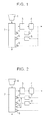
- a conventional carbonization furnace for formed coke requires gas removal through a coolant-gas-removal tuyere 10 at some point of a carbonization furnace main body 2. This makes the equipment complicated.
- the gas to be removed is a high-temperature gas heated by heat exchange with high-temperature coke after carbonization.
- the heated high-temperature gas is reused by introducing it into an intermediate portion of the carbonization furnace through a low-temperature-gas-blowing tuyere 5.
- this may cause heat loss.
- the production of carbon iron composite requires the reduction of iron oxide as well as the carbonization of coal.
- the production of carbon iron composite requires a larger amount of heat than the production of formed coke in a high temperature portion in which the reduction of iron oxide is activated. It is probably inappropriate in terms of heat balance to temporarily remove a high-temperature gas from the furnace and reuse it in a low-temperature portion (an intermediate portion of the carbonization furnace) as in the production of formed coke.
- the present invention employs simplified equipment for producing carbon iron composite in which an upper portion of the vertical carbonization furnace serves as a carbonization zone, a lower portion serves as a cooling zone, a heating medium gas is supplied from three points, that is, an intermediate portion and a lower portion of the carbonization zone and a lower portion of the cooling zone, a furnace gas is exhausted only through a top portion, and thereby a coolant-gas-removal tuyere installed in the production of formed coke is eliminated.
- Fig. 1 illustrates such equipment according to an embodiment.
- the equipment for producing carbon iron composite includes a carbonization furnace having a carbonization zone for carbonizing a formed product in an upper portion and a cooling zone for cooling carbon iron composite in a lower portion.
- a low-temperature-gas-blowing tuyere 5 is disposed in a position corresponding to an intermediate portion of the carbonization zone
- a high-temperature-gas-blowing tuyere 6 is disposed in a position corresponding to a lower portion of the carbonization zone
- a coolant-gas-blowing tuyere 9 is disposed in a position corresponding to a lower portion of the cooling zone
- a formed product charging port and a furnace gas outlet are disposed in a top portion of the carbonization furnace 2
- an carbon iron composite outlet is disposed in a lower portion of the carbonization furnace 2.
- a formed product of a carbon-containing substance and an iron-containing substance is fed with a formed product feeder 1 from the top portion of the vertical carbonization furnace main body 2, is carbonized in the carbonization zone, is cooled in the cooling zone, and is discharged from the lower portion.
- a heating gas for the carbonization of the formed product is blown into the furnace through the low-temperature-gas-blowing tuyere 5 and the high-temperature-gas-blowing tuyere 6.
- the gas blown into the furnace through the high-temperature-gas-blowing tuyere 6 has a higher temperature than the gas blown into the furnace through the low-temperature-gas-blowing tuyere 5.
- a coolant gas for cooling carbon iron composite is blown into the furnace through the coolant-gas-blowing tuyere 9. The gas blown into the furnace is exhausted only through the furnace gas outlet in the top portion.
- the furnace gas exhausted only from the top portion is cooled in circulating gas coolers 3 and 4. Part of the exhausted furnace gas is heated in a low-temperature gas heater 7 and is blown into the furnace through the low-temperature-gas-blowing tuyere 5. Another part of the exhausted furnace gas is heated in a high-temperature gas heater 8 and is blown into the furnace through the high-temperature-gas-blowing tuyere 6. The remainder of the exhausted furnace gas is blown into the furnace through the coolant-gas-blowing tuyere 9.
- a formed product of a carbon-containing substance and an iron-containing substance is continuously carbonized to produce carbon iron composite in the vertical carbonization furnace having the three tuyeres disposed at different heights and no gas outlet other than the gas outlet in the top portion while a low-temperature gas is blown into the furnace through the tuyere disposed in the intermediate portion of the carbonization zone, a high-temperature gas is blown into the furnace through the tuyere disposed in the lower portion of the carbonization zone, and a coolant gas is blown into the furnace through the tuyere disposed in the lower portion of the cooling zone.
- the production of carbon iron composite in this manner can decrease the amount of heat required for the production of carbon iron composite.
- the low-temperature gas blown into the furnace through the low-temperature-gas-blowing tuyere 5 is blown so as to control the top gas temperature and the heating rate of the solid in the carbonization furnace and preferably has a temperature in the range of approximately 400°C to 700°C.
- the high-temperature gas blown into the furnace through the high-temperature-gas-blowing tuyere 6 is blown so as to heat the solid to the maximum temperature and preferably has a temperature in the range of approximately 800°C to 1000°C.
- the coolant gas blown into the furnace through the coolant-gas-blowing tuyere 9 is blown so as to cool carbon iron composite produced by carbonization in the furnace and preferably has a temperature in the range of approximately 25°C to 80°C.
- the carbon-containing substance is a carbon material, coal
- the iron-containing substance is iron ore (ore).
- the reduction behavior of iron ore was examined in the carbonization process of a formed product.
- the reduction of iron oxide in the production of carbon iron composite can be broadly divided into direct reduction with solid carbon (see the following formula (1)) and gas reduction with CO gas and H 2 gas generated from coal (see the following formulae (2) and (3)).
- a formed product of coal and iron ore was carbonized in a small batch furnace while N 2 flowed.
- the type of reduction was determined on the basis of the composition of exhaust gases.
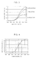
- Fig. 3 shows the results. At a temperature of 800°C or more, the percentage of the direct reduction with C (formula (1)) increases significantly, and the amount of endothermic heat during the reduction increases. Thus, the operational design for the production of carbon iron composite must compensate for an endothermic reaction at a temperature of 800°C or more.
- the temperature distribution of the furnace was estimated using a one-dimensional numerical formula model on the basis of the relationship shown in Fig. 3 and the relationship between the temperature and the reduction rate shown in Fig. 4 determined by the experiment.
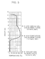
- Fig. 5 shows the calculation results for carbon iron composite production equipment without coolant-gas-removal tuyere according to the present invention illustrated in Fig. 1 .
- Fig. 6 shows the calculation results for conventional formed coke production equipment having the coolant-gas-removal tuyere 10 illustrated in Fig. 2 .
- Gas conditions satisfying the target temperature distribution were determined such that a region having a temperature of 900°C took one to two hours.
- A denotes the position of the low-temperature-gas-blowing tuyere, and a gas having a temperature of 500°C was blown into the furnace at 576 Nm 3 /t.
- B denotes the position of the high-temperature-gas-blowing tuyere, and a gas having a temperature of 980°C was blown into the furnace at 1152 Nm 3 /t.
- D denotes the position of the coolant-gas-blowing tuyere, and a gas having a temperature of 35°C was blown into the furnace at 952 Nm 3 /t.
- A denotes the position of the low-temperature-gas-blowing tuyere, and a gas having a temperature of 600°C was blown into the furnace at 514 Nm 3 /t.
- B denotes the position of the high-temperature-gas-blowing tuyere, and a gas having a temperature of 950°C was blown into the furnace at 1740 Nm 3 /t.
- C denotes the position of the coolant-gas-removal tuyere, and a gas having a temperature of 880°C was removed at 941 Nm 3 /t.
- D denotes the position of the coolant-gas-blowing tuyere, and a gas having a temperature of 35°C was blown into the furnace at 941 Nm 3 /t .
- the amount of heat required for a high-temperature portion of the carbonization zone must be supplied through the high-temperature-gas-blowing tuyere 6.
- the amount of gas blown through the high-temperature-gas-blowing tuyere 6 is higher than that for the equipment without coolant-gas-removal tuyere according to the present invention illustrated in Fig. 1 .
- Table 1 shows the ratio of the gas flow rate of the low-temperature-gas-blowing tuyere to the gas flow rate of the high-temperature-gas-blowing tuyere for the production of formed coke with the conventional equipment as described in Patent Document 1 illustrated in Fig. 2 and the production of carbon iron composite examined above.
- Table 1 Formed coke Carbon iron composite With removal of coolant- gas Without removal of coolant gas Low-temperature gas blowing tuyere 1.88 0.30 0.50 High-temperature gas blowing tuyere 1.00 1.00 1.00
- the amount of gas through the high-temperature tuyere is higher in the production of carbon iron composite than in the production of formed coke. This is because the production of carbon iron composite requires a larger amount of heat in the high-temperature portion than the production of formed coke because of the reduction of ore. This clearly shows that even with the same vertical furnace the operational designs for the production of conventional formed coke and the production of carbon iron composite must be different.
- the embodiment described above considers the reuse (blowing into the furnace through each tuyere) of the top gas temporarily cooled to the vicinity of normal temperature.
- it is referred to circulate a gas exhausted from the vertical carbonization furnace.
- the top gas blown into the high-temperature-gas-blowing tuyere and the low-temperature-gas-blowing tuyere must therefore be heated to a predetermined temperature. This heating requires the partial combustion of the top gas or the combustion of fuel, such as LNG, supplied from the outside. This process requires energy.
- Table 2 shows the sensible heat of gas blown through a tuyere in the presence or absence of the coolant-gas-removal tuyere illustrated in Figs. 1 and 2 and Figs.
- the sensible heat of gas in the low-temperature tuyere was 0 (-).
- the amount of gas blown through the high-temperature-gas-blowing tuyere must be increased.
- the total sensible heat of blown gas is higher in the presence of the coolant-gas-removal tuyere than in the absence of the coolant-gas-removal tuyere. This indicates that much energy is required to heat a gas in the outside of the furnace.
- energy required in the production of carbon iron composite is lower in the absence of the coolant-gas-removal tuyere according to the present invention illustrated in Fig. 1 than in the presence thereof.
- the test production of carbon iron composite was performed with a test apparatus for producing carbon iron composite illustrated in Fig. 7 in the presence or absence of a coolant-gas-removal tuyere 10.
- a vertical carbonization furnace had a cross-sectional area of 1.67 m 2 .
- Paten Document 1 in which a coolant gas inlet has a smaller cross-sectional area than a high-temperature-gas inlet, when a coolant gas is not removed, the coolant gas selectively flows through the central portion of the furnace in the high-temperature-gas inlet, resulting in poor mixing of a high-temperature gas and the coolant gas.
- a coolant gas inlet had the same cross-sectional area as a high-temperature-gas inlet so as to improve gas mixing. Furthermore, a formed product as an carbon iron composite raw material was sieved to remove a powder having a particle size of 10 mm or less and fragments of the formed product. The sieved formed product was fed into a carbonization furnace while maintaining high air permeability of the packed bed. This facilitated the flow of the high-temperature gas through the packed bed.
- Table 3 shows the operational specifications for an carbon iron composite production volume of 50 t/d.
- the target carbonization temperature ranged from 800°C to 950°C, and the temperature of a high-temperature blast from a high-temperature-gas-blowing tuyere was altered.
- the carbonization temperature is the mean value of temperatures measured during the operation at heights of 0.1 and 1 m with respect to the high-temperature tuyere.
- Table 3 also shows the reduction rate of iron and the percentage of metallization in carbonized carbon iron composite measured for each condition.
- the reduction rate is 40%, and the percentage of metallization is more than 25%, indicating that iron ore in the carbon iron composite is reduced to form metallic iron.
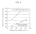
- Fig. 8 shows the relationship between the carbonization temperature and the total amount of heat required (necessary heat) to increase the temperatures of the low-temperature gas and the high-temperature gas.
- the amount of heat required is approximately 860 Mcal/h or more without removal of the coolant gas and 965 Mcal/h or more with removal of the coolant gas.
- the amount of heat required in the presence of removal of the coolant gas is larger than that in the absence of removal of the coolant gas for the same carbonization temperature. The difference in the amount of heat between them increases with the temperature of carbonization.
- the conditions in the absence of removal of the coolant gas required a smaller amount of heat to increase the temperature of gas than the conditions in the presence of removal of the coolant gas and required smaller energy consumption in the production of carbon iron composite than the conditions in the presence of removal of the coolant gas.
Landscapes
- Chemical & Material Sciences (AREA)
- Engineering & Computer Science (AREA)
- Oil, Petroleum & Natural Gas (AREA)
- Materials Engineering (AREA)
- Organic Chemistry (AREA)
- Combustion & Propulsion (AREA)
- Chemical Kinetics & Catalysis (AREA)
- General Chemical & Material Sciences (AREA)
- Coke Industry (AREA)
- Vertical, Hearth, Or Arc Furnaces (AREA)
- Manufacture Of Iron (AREA)
- Carbon And Carbon Compounds (AREA)
Abstract
Description
- The present invention relates to a method and an apparatus for producing carbon iron composite (ferrocoke) in which a formed product of a carbon-containing substance and an iron-containing substance is continuously carbonized in a vertical carbonization furnace to produce metallic iron in coke.
- Metallurgical coke, which is produced by coal carbonized in a coke oven, is generally used in the operation of a blast furnace. In recent years, from the viewpoint of improving the reactivity of coke, there has been known a technique for using metallurgical carbon iron composite, which is produced by carbonizing a mixture of coal and iron ore, in the operation of a blast furnace. Carbon iron composite can increase the CO2 reactivity of coke in the carbon iron composite by the catalytic effect of reduced iron ore and can decrease the percentage of a reducing material as a result of a decrease in thermal reserve zone temperature.
- Studies have been carried out on a technique for carbonizing a carbon-containing substance, such as coal, and an iron-containing substance, such as iron ore, in a common chamber coke oven to produce carbon iron composite, for example, a) a method for feeding a mixture of coal and iron ore fines into a chamber coke oven or b) a method for cold-forming coal and iron ore at room temperature and feeding the formed product into a chamber coke oven (see, for example, Non Patent Document 1).
- However, since conventional coke ovens are constructed of silica stone bricks, iron ore in a chamber coke oven can react with the main component of the silica stone bricks, silica, to form low-melting-point fayalite, causing damage to the silica stone bricks. Thus, a technique for producing carbon iron composite in a chamber coke oven has not been industrially employed.
- As a substitute for a method for producing coke in a chamber oven, a method for continuously producing formed coke has been developed. In the method for continuously producing formed coke, a vertical shaft furnace constructed of chamotte bricks in place of silica stone bricks is used as a carbonization furnace. Coal is cold-formed in a predetermined size and is fed into a vertical shaft furnace. The briquettes are carbonized by heating with a circulating heating gas to produce formed coke. It has been demonstrated that coke having a strength comparable to that of coke produced with a conventional coke oven can be produced even by using a large amount of naturally abundant and inexpensive non- or slightly-caking coal.
- One known method for continuously producing formed coke is characterized in that a top gas of a vertical carbonization furnace is utilized as a coolant gas into a lower portion of a cooling chamber directly coupled to a carbonization chamber of the vertical carbonization furnace, and most of the gas passing through the cooling chamber is exhausted from an upper portion of the cooling chamber and is supplied as a heating gas to an inlet in an intermediate portion of the carbonization furnace (see, for example, Patent Document 1). This method requires three gas inlets (an intermediate portion of the carbonization chamber, a lower portion of the carbonization chamber, and a lower portion of the cooling chamber) and one gas outlet (an upper portion of the cooling chamber), which makes the equipment complicated. Sensible heat generated by the cooling of high-temperature coke after carbonization is recovered with a gas and is reused by supplying the heat to an intermediate portion of the carbonization furnace. However, there is a problem of heat loss. In order to simplify the equipment, another method for producing formed coke is disclosed which does not require the removal of gas from an intermediate portion of a vertical carbonization furnace (see Patent Document 2). In accordance with this method, coke after carbonization is cooled in a water tank instead of using a gas. One of characteristics of carbon iron composite is that iron ore can be reduced to metallic iron during carbonization, and its catalytic effect can increase reactivity. A water cooling method may cause reoxidation of metallic iron and therefore cannot be employed for the production of carbon iron composite.
-
- Patent Document 1: Japanese Examined Patent Application Publication No.
56-47234 - Patent Document 2: Japanese Unexamined Patent Application Publication No.
52-23107 - Patent Document 3: Japanese Unexamined Patent Application Publication No.
6-65579 -
- Non Patent Document 1: Fuel Society of Japan, "Kokusu Gijutsu Nenpou (annual report on coke technology)", 1958, p. 38
- As described above, chamber coke ovens constructed of silica stone bricks are difficult to use in the production of carbon iron composite. It will therefore be desirable to use a vertical carbonization furnace having multiple tuyeres using the same type of gas as in formed coke as a heating medium, for example, a vertical shaft furnace constructed of chamotte bricks. However, considering the use of a vertical continuous carbonization furnace having a cooling function, a conventional carbonization furnace for formed coke requires gas removal at some point of the furnace, which makes the equipment complicated. Furthermore, carbon iron composite requires the reduction of an iron-containing substance. Thus, a conventional method for producing formed coke cannot be directly used for carbon iron composite. The operational specifications, such as gas distribution in tuyeres, must be reconsidered. Furthermore, energy conservation cannot be avoided in future iron-manufacturing processes, necessitating a design concept of minimizing energy required for the production of carbon iron composite.
- Accordingly, it is an object of the present invention to solve these problems of related art and provide a method and an apparatus for producing carbon iron composite in which the production of metallurgical carbon iron composite with a vertical carbonization furnace can be performed with simplified equipment with decreased energy consumption.
- In order to solve these problems, the present invention has the following aspects:
- (1) A method for producing carbon iron composite, including the steps of:
- providing a carbonization furnace having a top portion, a carbonization zone in an upper portion, and a cooling zone in a lower portion;
- feeding a formed product of a carbon-containing substance and an iron-containing substance into a carbonization furnace;
- carbonizing the formed product in the carbonization zone to produce carbon iron composite;
- blowing a coolant gas into the furnace through a coolant-gas-blowing tuyere disposed in the cooling zone to cool the carbon iron composite; and
- exhausting a furnace gas through an outlet in the top portion,
- wherein the carbonization involves supplying the coolant gas after the coolant gas has undergone heat exchange with the carbon iron composite in the cooling zone to the carbonization zone, blowing a high-temperature gas into the furnace through a high-temperature-gas-blowing tuyere disposed in a lower portion of the carbonization zone, and blowing a low-temperature gas into the furnace through a low-temperature-gas-blowing tuyere disposed in an intermediate portion of the carbonization zone.
- (2) The method for producing carbon iron composite according to (1), wherein the furnace gas is exhausted only through the outlet in the top portion.
- (3) The method for producing carbon iron composite according to (1), further including supplying the furnace gas exhausted through the outlet in the top portion to the low-temperature-gas-blowing tuyere.
- (4) The method for producing carbon iron composite according to (1), further including supplying the furnace gas exhausted through the outlet in the top portion to the high-temperature-gas-blowing tuyere.
- (5) The method for producing carbon iron composite according to (1), further including supplying the furnace gas exhausted through the outlet in the top portion to the coolant-gas-blowing tuyere.
- (6) The method for producing carbon iron composite according to (1), further including supplying the furnace gas exhausted through the outlet in the top portion to the low-temperature-gas-blowing tuyere, the high-temperature-gas-blowing tuyere, and the coolant-gas-blowing tuyere.
- (7) The method for producing carbon iron composite according to (1), wherein the gas blown into the furnace through the low-temperature-gas-blowing tuyere has a temperature in the range of 400°C to 700°C.
- (8) The method for producing carbon iron composite according to (1), wherein the gas blown into the furnace through the high-temperature-gas-blowing tuyere has a temperature in the range of 800°C to 1000°C.
- (9) The method for producing carbon iron composite according to (1), wherein the gas blown into the furnace through the coolant-gas-blowing tuyere has a temperature in the range of 25°C to 80°C.
- (10) An apparatus for carbonizing a formed product of a carbon-containing substance and an iron-containing substance to continuously produce carbon iron composite, the apparatus including:
- a carbonization furnace main body having a carbonization zone for carbonizing the formed product in an upper portion and a cooling zone for cooling the formed product in a lower portion;
- a charging port for charging the formed product into the furnace, the charging port being disposed in a top portion of the carbonization furnace main body;
- a low-temperature-gas-blowing tuyere for blowing a low-temperature gas into the furnace to heat the formed product, the low-temperature-gas-blowing tuyere being disposed in an intermediate portion of the carbonization zone;
- a high-temperature-gas-blowing tuyere for blowing a high-temperature gas into the furnace to heat the formed product, the high-temperature-gas-blowing tuyere being disposed in a lower portion of the carbonization zone;
- a coolant-gas-blowing tuyere for blowing a coolant gas for cooling carbon iron composite into the furnace, the coolant-gas-blowing tuyere being disposed in a lower portion of the cooling zone, the blown coolant gas flowing to the cooling zone and the carbonization zone;
- a furnace gas outlet for exhausting a furnace gas, the furnace gas outlet being disposed in the top portion of the carbonization furnace main body; and
- a carbon iron composite outlet disposed in a lower portion of the carbonization furnace main body.
- (11) The apparatus for producing carbon iron composite according to (10), wherein the furnace gas is exhausted only through the outlet in the top portion.
- (12) The apparatus for producing carbon iron composite according to (10), wherein the horizontal cross-sectional area of the carbonization furnace main body at the position of the coolant-gas-blowing tuyere is substantially the same as the horizontal cross-sectional area of the carbonization furnace main body at the position of the high-temperature-gas-blowing tuyere.
- In accordance with the present invention, carbon iron composite can be continuously produced with simplified equipment with decreased energy consumption. Thus, reactive carbon iron composite can be used in the operation of a blast furnace, thereby effectively decreasing the percentage of a reducing material.
-
-
Fig. 1 is a schematic view of an embodiment of the present invention. -
Fig. 2 is a schematic view of an embodiment of a comparative example. -
Fig. 3 is a graph showing the reduction of ore for each reaction in the carbon iron composite carbonization process. -
Fig. 4 is a graph showing the reduction rate of ore in the carbon iron composite carbonization process as a function of temperature. -
Fig. 5 is a graph showing the calculation results of the temperature distribution in a carbonization furnace in the present invention. -
Fig. 6 is a graph showing the calculation results of the temperature distribution in a carbonization furnace in a comparative example. -
Fig. 7 is a schematic view of an apparatus used in the production test of carbon iron composite in an example. -
Fig. 8 is a graph showing the relationship between the carbonization temperature and the amount of heat required to increase the temperatures of a low-temperature gas and a high-temperature gas in the present invention. - As described above, the present inventors concluded that vertical continuous carbonization furnaces having a cooling function are more suitable for the production of carbon iron composite than chamber coke ovens. As illustrated in
Fig. 2 , a conventional carbonization furnace for formed coke requires gas removal through a coolant-gas-removal tuyere 10 at some point of a carbonization furnacemain body 2. This makes the equipment complicated. The gas to be removed is a high-temperature gas heated by heat exchange with high-temperature coke after carbonization. In this formed coke production process, the heated high-temperature gas is reused by introducing it into an intermediate portion of the carbonization furnace through a low-temperature-gas-blowingtuyere 5. However, this may cause heat loss. Furthermore, the production of carbon iron composite requires the reduction of iron oxide as well as the carbonization of coal. Thus, the production of carbon iron composite requires a larger amount of heat than the production of formed coke in a high temperature portion in which the reduction of iron oxide is activated. It is probably inappropriate in terms of heat balance to temporarily remove a high-temperature gas from the furnace and reuse it in a low-temperature portion (an intermediate portion of the carbonization furnace) as in the production of formed coke. - Thus, in the production of carbon iron composite containing metallic iron by continuously carbonizing a formed product of a carbon-containing substance and an iron-containing substance in a vertical carbonization furnace to produce metallic iron in coke, the present invention employs simplified equipment for producing carbon iron composite in which an upper portion of the vertical carbonization furnace serves as a carbonization zone, a lower portion serves as a cooling zone, a heating medium gas is supplied from three points, that is, an intermediate portion and a lower portion of the carbonization zone and a lower portion of the cooling zone, a furnace gas is exhausted only through a top portion, and thereby a coolant-gas-removal tuyere installed in the production of formed coke is eliminated.
Fig. 1 illustrates such equipment according to an embodiment. - In
Fig. 1 , the equipment for producing carbon iron composite includes a carbonization furnace having a carbonization zone for carbonizing a formed product in an upper portion and a cooling zone for cooling carbon iron composite in a lower portion. On the side of thecarbonization furnace 2, a low-temperature-gas-blowingtuyere 5 is disposed in a position corresponding to an intermediate portion of the carbonization zone, a high-temperature-gas-blowingtuyere 6 is disposed in a position corresponding to a lower portion of the carbonization zone, a coolant-gas-blowingtuyere 9 is disposed in a position corresponding to a lower portion of the cooling zone, a formed product charging port and a furnace gas outlet are disposed in a top portion of thecarbonization furnace 2, and an carbon iron composite outlet is disposed in a lower portion of thecarbonization furnace 2. - In the production of carbon iron composite, a formed product of a carbon-containing substance and an iron-containing substance is fed with a formed
product feeder 1 from the top portion of the vertical carbonization furnacemain body 2, is carbonized in the carbonization zone, is cooled in the cooling zone, and is discharged from the lower portion. A heating gas for the carbonization of the formed product is blown into the furnace through the low-temperature-gas-blowingtuyere 5 and the high-temperature-gas-blowingtuyere 6. The gas blown into the furnace through the high-temperature-gas-blowingtuyere 6 has a higher temperature than the gas blown into the furnace through the low-temperature-gas-blowingtuyere 5. A coolant gas for cooling carbon iron composite is blown into the furnace through the coolant-gas-blowingtuyere 9. The gas blown into the furnace is exhausted only through the furnace gas outlet in the top portion. - The furnace gas exhausted only from the top portion is cooled in circulating
gas coolers temperature gas heater 7 and is blown into the furnace through the low-temperature-gas-blowingtuyere 5. Another part of the exhausted furnace gas is heated in a high-temperature gas heater 8 and is blown into the furnace through the high-temperature-gas-blowingtuyere 6. The remainder of the exhausted furnace gas is blown into the furnace through the coolant-gas-blowingtuyere 9. - A formed product of a carbon-containing substance and an iron-containing substance is continuously carbonized to produce carbon iron composite in the vertical carbonization furnace having the three tuyeres disposed at different heights and no gas outlet other than the gas outlet in the top portion while a low-temperature gas is blown into the furnace through the tuyere disposed in the intermediate portion of the carbonization zone, a high-temperature gas is blown into the furnace through the tuyere disposed in the lower portion of the carbonization zone, and a coolant gas is blown into the furnace through the tuyere disposed in the lower portion of the cooling zone. The production of carbon iron composite in this manner can decrease the amount of heat required for the production of carbon iron composite.
- The low-temperature gas blown into the furnace through the low-temperature-gas-blowing
tuyere 5 is blown so as to control the top gas temperature and the heating rate of the solid in the carbonization furnace and preferably has a temperature in the range of approximately 400°C to 700°C. The high-temperature gas blown into the furnace through the high-temperature-gas-blowingtuyere 6 is blown so as to heat the solid to the maximum temperature and preferably has a temperature in the range of approximately 800°C to 1000°C. The coolant gas blown into the furnace through the coolant-gas-blowingtuyere 9 is blown so as to cool carbon iron composite produced by carbonization in the furnace and preferably has a temperature in the range of approximately 25°C to 80°C. - The circumstances leading up to the present invention will be described in detail below. In the following description, the carbon-containing substance is a carbon material, coal, and the iron-containing substance is iron ore (ore).
- In the production of carbon iron composite, not only the carbonization of coal but also the reduction of ore therein require heat. Thus, the operational specifications for the production of formed coke cannot be employed without modification. In the present invention, the operational specifications for a vertical carbonization furnace in the production of carbon iron composite was examined on the basis of studies on the basic characteristics of carbonization and reduction and the simulation for a carbonization furnace based on the studies.
- First, as basic characteristics, the reduction behavior of iron ore was examined in the carbonization process of a formed product. The reduction of iron oxide in the production of carbon iron composite can be broadly divided into direct reduction with solid carbon (see the following formula (1)) and gas reduction with CO gas and H2 gas generated from coal (see the following formulae (2) and (3)).
Fe2O3 + 3C → 2Fe + 3CO -ΔH298 = -676.1 (kcal/kg-Fe2O3) (1)
Fe2O3 + 3Hz → 2Fe + 3H2O -ΔH298 = -142.5 (kcal/kg-Fe2O3) (2)
Fe2O3 + 3CO → 2Fe + 3CO2 -ΔH298 = +42.0 (kcal/kg-Fe2O3) (3)
- The direct reduction of the formula (1) involves a highly endothermic reaction.
- A formed product of coal and iron ore was carbonized in a small batch furnace while N2 flowed. The type of reduction was determined on the basis of the composition of exhaust gases.
Fig. 3 shows the results. At a temperature of 800°C or more, the percentage of the direct reduction with C (formula (1)) increases significantly, and the amount of endothermic heat during the reduction increases. Thus, the operational design for the production of carbon iron composite must compensate for an endothermic reaction at a temperature of 800°C or more. - The temperature distribution of the furnace was estimated using a one-dimensional numerical formula model on the basis of the relationship shown in
Fig. 3 and the relationship between the temperature and the reduction rate shown inFig. 4 determined by the experiment.Fig. 5 shows the calculation results for carbon iron composite production equipment without coolant-gas-removal tuyere according to the present invention illustrated inFig. 1 .Fig. 6 shows the calculation results for conventional formed coke production equipment having the coolant-gas-removal tuyere 10 illustrated inFig. 2 . Gas conditions satisfying the target temperature distribution were determined such that a region having a temperature of 900°C took one to two hours. - In
Fig. 5 , A denotes the position of the low-temperature-gas-blowing tuyere, and a gas having a temperature of 500°C was blown into the furnace at 576 Nm3/t. B denotes the position of the high-temperature-gas-blowing tuyere, and a gas having a temperature of 980°C was blown into the furnace at 1152 Nm3/t. D denotes the position of the coolant-gas-blowing tuyere, and a gas having a temperature of 35°C was blown into the furnace at 952 Nm3/t. - In
Fig. 6 , A denotes the position of the low-temperature-gas-blowing tuyere, and a gas having a temperature of 600°C was blown into the furnace at 514 Nm3/t. B denotes the position of the high-temperature-gas-blowing tuyere, and a gas having a temperature of 950°C was blown into the furnace at 1740 Nm3/t. C denotes the position of the coolant-gas-removal tuyere, and a gas having a temperature of 880°C was removed at 941 Nm3/t. D denotes the position of the coolant-gas-blowing tuyere, and a gas having a temperature of 35°C was blown into the furnace at 941 Nm3/t. - In the case of the conventional equipment having the coolant-gas-
removal tuyere 10 illustrated inFig. 2 , in order to temporarily exhaust a gas blown through a lower portion of the furnace and heated to approximately 900°C by heat exchange with a high-temperature carbonized formed product, the amount of heat required for a high-temperature portion of the carbonization zone must be supplied through the high-temperature-gas-blowingtuyere 6. Thus, the amount of gas blown through the high-temperature-gas-blowingtuyere 6 is higher than that for the equipment without coolant-gas-removal tuyere according to the present invention illustrated inFig. 1 . - Table 1 shows the ratio of the gas flow rate of the low-temperature-gas-blowing tuyere to the gas flow rate of the high-temperature-gas-blowing tuyere for the production of formed coke with the conventional equipment as described in
Patent Document 1 illustrated inFig. 2 and the production of carbon iron composite examined above.Table 1 Formed coke Carbon iron composite With removal of coolant- gas Without removal of coolant gas Low-temperature gas blowing tuyere 1.88 0.30 0.50 High-temperature gas blowing tuyere 1.00 1.00 1.00 - The amount of gas through the high-temperature tuyere is higher in the production of carbon iron composite than in the production of formed coke. This is because the production of carbon iron composite requires a larger amount of heat in the high-temperature portion than the production of formed coke because of the reduction of ore. This clearly shows that even with the same vertical furnace the operational designs for the production of conventional formed coke and the production of carbon iron composite must be different.
- The embodiment described above considers the reuse (blowing into the furnace through each tuyere) of the top gas temporarily cooled to the vicinity of normal temperature. In the present invention, it is referred to circulate a gas exhausted from the vertical carbonization furnace. The top gas blown into the high-temperature-gas-blowing tuyere and the low-temperature-gas-blowing tuyere must therefore be heated to a predetermined temperature. This heating requires the partial combustion of the top gas or the combustion of fuel, such as LNG, supplied from the outside. This process requires energy. Table 2 shows the sensible heat of gas blown through a tuyere in the presence or absence of the coolant-gas-removal tuyere illustrated in
Figs. 1 and 2 andFigs. 5 and6 with respect to 35°C.Table 2 With coolant gas removal tuyere Without coolant gas removal tuyere Low-temperature gas blowing tuyere - 88 Mcal/t High-temperature gas blowing tuyere 531 Mcal/t 358 Mcal/t Total 531 Mcal/t 446 Mcal/t - Energy corresponding to the sensible heat shown in Table 2 must be supplied from the outside. In both cases, the high-temperature gas is the top gas cooled to 35°C and then heated in the outside of the furnace. In the absence of the coolant-gas-removal tuyere as illustrated in
Figs. 1 and5 , the low-temperature gas must be heated in the outside of the furnace. In the presence of the coolant-gas-removal tuyere as illustrated inFigs. 2 and6 , a gas heated by heat exchange with coke is removed from the furnace and then blown into the furnace, thus obviating the necessity for heating in the outside of the furnace. The necessity for heating in the outside of the furnace is taken into account in Table 2. Thus, in the presence of the coolant-gas-removal tuyere, the sensible heat of gas in the low-temperature tuyere was 0 (-). As described above, in the presence of the coolant-gas-removal tuyere, the amount of gas blown through the high-temperature-gas-blowing tuyere must be increased. Even in no need of heating for the low-temperature tuyere, the total sensible heat of blown gas is higher in the presence of the coolant-gas-removal tuyere than in the absence of the coolant-gas-removal tuyere. This indicates that much energy is required to heat a gas in the outside of the furnace. In conclusion, energy required in the production of carbon iron composite is lower in the absence of the coolant-gas-removal tuyere according to the present invention illustrated inFig. 1 than in the presence thereof. - In the case of a vertical carbonization furnace used in a method for continuously producing formed coke in which a coolant gas is removed described above in the related art, a technique for producing carbon iron composite is also disclosed (see Patent Document 3). However, blowing conditions and energy supplied are not specified. In the present invention, a method for decreasing energy required for the production of carbon iron composite was found as a result of examination of a difference in equipment structure, more specifically, the presence or absence of the coolant-gas-removal tuyere. Thus, the present invention cannot be deduced from equipment structures having a coolant-gas-removal tuyere.
- The test production of carbon iron composite was performed with a test apparatus for producing carbon iron composite illustrated in
Fig. 7 in the presence or absence of a coolant-gas-removal tuyere 10. A vertical carbonization furnace had a cross-sectional area of 1.67 m2. In accordance with the related art described inPaten Document 1 in which a coolant gas inlet has a smaller cross-sectional area than a high-temperature-gas inlet, when a coolant gas is not removed, the coolant gas selectively flows through the central portion of the furnace in the high-temperature-gas inlet, resulting in poor mixing of a high-temperature gas and the coolant gas. In the present invention, a coolant gas inlet had the same cross-sectional area as a high-temperature-gas inlet so as to improve gas mixing. Furthermore, a formed product as an carbon iron composite raw material was sieved to remove a powder having a particle size of 10 mm or less and fragments of the formed product. The sieved formed product was fed into a carbonization furnace while maintaining high air permeability of the packed bed. This facilitated the flow of the high-temperature gas through the packed bed. - Table 3 shows the operational specifications for an carbon iron composite production volume of 50 t/d. The target carbonization temperature ranged from 800°C to 950°C, and the temperature of a high-temperature blast from a high-temperature-gas-blowing tuyere was altered. The carbonization temperature is the mean value of temperatures measured during the operation at heights of 0.1 and 1 m with respect to the high-temperature tuyere. Table 3 also shows the reduction rate of iron and the percentage of metallization in carbonized carbon iron composite measured for each condition.
Table 3 VVithout removal of coolant gas With removal of coolant gas Low-temperature °C 480 480 480 480 600 600 600 gas blowing tuyere Nm3/hr 1200 1200 1200 1200 1071 1071 1071 High-temperature °C 890 930 980 1020 850 910 960 gas blowing tuyere Nm3/hr 2400 2400 2400 2400 3625 3625 3625 Coolant gas °C - - - - 770 830 880 removal tuyere Nm3/hr - - - - 0 3625 3625 Coolant gas °C 35 35 35 35 35 35 35 blowing tuyere Nm3/hr 1979 1979 1979 1979 1960 1960 1960 Carbonization temperature °C 801 858 905 958 800 854 900 Redaction rate of iron ore in carbon iron composite % 45 72 88 92 46 71 87 Percentage of metallization of iron ore in carbon iron composite % 25 65 83 89 26 64 81 - At a carbonization temperature of 800°C or more, the reduction rate is 40%, and the percentage of metallization is more than 25%, indicating that iron ore in the carbon iron composite is reduced to form metallic iron.
- Regardless of the presence or absence of the coolant-gas-
removal tuyere 10, carbon iron composite thus produced had a target strength without any problem in the production. Table 4 shows the amount of heat required to increase the temperature of gases blown through the low-temperature-gas-blowing tuyere and the high-temperature-gas-blowing tuyere for each condition. The definition is the same as described above, that is, the sensible heat of gas blown through each tuyere with respect to 35°C.Table 4 Without removal of coolant gas With removal of coolant gas Carbonization temperature. °C 801 853 905 958 800 854 900 Low-temperature gas blowing tuyere Mcal/hr 184 184 184 184 0 0 0 High-temperature gas blowing tuyere Mcal/hr 677 711 745 780 965 1042 1106 Total Mcal/hr 861 895 929 964 965 1042 1106 -
Fig. 8 shows the relationship between the carbonization temperature and the total amount of heat required (necessary heat) to increase the temperatures of the low-temperature gas and the high-temperature gas. If the lower limit condition of the carbonization temperature is 800°C, the amount of heat required is approximately 860 Mcal/h or more without removal of the coolant gas and 965 Mcal/h or more with removal of the coolant gas. Also at a temperature of 800°C or more, the amount of heat required in the presence of removal of the coolant gas is larger than that in the absence of removal of the coolant gas for the same carbonization temperature. The difference in the amount of heat between them increases with the temperature of carbonization. Thus, at a carbonization temperature of 800°C or more at which iron ore in carbon iron composite was reduced to form metallic iron, the conditions in the absence of removal of the coolant gas required a smaller amount of heat to increase the temperature of gas than the conditions in the presence of removal of the coolant gas and required smaller energy consumption in the production of carbon iron composite than the conditions in the presence of removal of the coolant gas. -
- 1 Formed product feeder
- 2 Vertical carbonization furnace main body
- 3 Circulating gas cooler
- 4 Circulating gas cooler
- 5 Low-temperature-gas-blowing tuyere
- 6 High-temperature-gas-blowing tuyere
- 7 Low-temperature gas heater
- 8 High-temperature gas heater
- 9 Coolant-gas-blowing tuyere
- 10 Coolant-gas-removal tuyere
- A Position of low-temperature-gas-blowing tuyere
- B Position of high-temperature-gas-blowing tuyere
- C Position of coolant-gas-removal tuyere
- D Position of coolant-gas-blowing tuyere
- E Stock line
Claims (12)
- A method for producing carbon iron composite, comprising the steps of:providing a carbonization furnace having a top portion, a carbonization zone in an upper portion, and a cooling zone in a lower portion;feeding a formed product of a carbon-containing substance and an iron-containing substance into a carbonization furnace;carbonizing the formed product in the carbonization zone to produce carbon iron composite;blowing a coolant gas into the furnace through a coolant-gas-blowing tuyere disposed in the cooling zone to cool the carbon iron composite;exhausting a furnace gas through an outlet in the top portion; anddischarging the carbon iron composite through a lower portion of the cooling zone,wherein the carbonization step comprises:supplying the coolant gas after the coolant gas has undergone heat exchange with the carbon iron composite in the cooling zone to the carbonization zone,blowing a high-temperature gas into the furnace through a high-temperature-gas-blowing tuyere disposed in a lower portion of the carbonization zone, andblowing a low-temperature gas into the furnace through a low-temperature-gas-blowing tuyere disposed in an intermediate portion of the carbonization zone.
- The method for producing carbon iron composite according to claim 1, wherein the furnace gas is exhausted only through the outlet in the top portion.
- The method for producing carbon iron composite according to claim 1, further comprising supplying the furnace gas exhausted through the outlet in the top portion to the low-temperature-gas-blowing tuyere.
- The method for producing carbon iron composite according to claim 1, further comprising supplying the furnace gas exhausted through the outlet in the top portion to the high-temperature-gas-blowing tuyere.
- The method for producing carbon iron composite according to claim 1, further comprising supplying the furnace gas exhausted through the outlet in the top portion to the coolant-gas-blowing tuyere.
- The method for producing carbon iron composite according to claim 1, further comprising supplying the furnace gas exhausted through the outlet in the top portion to the low-temperature-gas-blowing tuyere, the high-temperature-gas-blowing tuyere, and the coolant-gas-blowing tuyere.
- The method for producing carbon iron composite according to claim 1, wherein the gas blown into the furnace through the low-temperature-gas-blowing tuyere has a temperature in the range of 400°C to 700°C.
- The method for producing carbon iron composite according to claim 1, wherein the gas blown into the furnace through the high-temperature-gas-blowing tuyere has a temperature in the range of 800°C to 1000°C.
- The method for producing carbon iron composite according to claim 1, wherein the gas blown into the furnace through the coolant-gas-blowing tuyere has a temperature in the range of 25°C to 80°C.
- An apparatus for carbonizing a formed product of a carbon-containing substance and an iron-containing substance to continuously produce carbon iron composite, the apparatus comprising:a carbonization furnace main body having a carbonization zone for carbonizing the formed product in an upper portion and a cooling zone for cooling the formed product in a lower portion;a charging port for charging the formed product into the furnace, the charging port being disposed in a top portion of the carbonization furnace main body;a low-temperature-gas-blowing tuyere for blowing a low-temperature gas into the furnace to heat the formed product, the low-temperature-gas-blowing tuyere being disposed in an intermediate portion of the carbonization zone;a high-temperature-gas-blowing tuyere for blowing a high-temperature gas into the furnace to heat the formed product, the high-temperature-gas-blowing tuyere being disposed in a lower portion of the carbonization zone;a coolant-gas-blowing tuyere for blowing a coolant gas for cooling carbon iron composite into the furnace, the coolant-gas-blowing tuyere being disposed in a lower portion of the cooling zone, the blown coolant gas flowing to the cooling zone and the carbonization zone;a furnace gas outlet for exhausting a furnace gas, the furnace gas outlet being disposed in the top portion of the carbonization furnace main body; anda carbon iron composite outlet disposed in a lower portion of the carbonization furnace main body.
- The apparatus for producing carbon iron composite according to claim 10, wherein the furnace gas is exhausted only through the outlet in the top portion.
- The apparatus for producing carbon iron composite according to claim 10, wherein the horizontal cross-sectional area of the carbonization furnace main body at the position of the coolant-gas-blowing tuyere is substantially the same as the horizontal cross-sectional area of the carbonization furnace main body at the position of the high-temperature-gas-blowing tuyere.
Applications Claiming Priority (3)
| Application Number | Priority Date | Filing Date | Title |
|---|---|---|---|
| JP2009185410 | 2009-08-10 | ||
| JP2010167786A JP4666114B2 (en) | 2009-08-10 | 2010-07-27 | Ferro-coke manufacturing method and manufacturing apparatus |
| PCT/JP2010/063143 WO2011018964A1 (en) | 2009-08-10 | 2010-07-28 | Ferro-coke producing method and producing device |
Publications (2)
| Publication Number | Publication Date |
|---|---|
| EP2450419A1 true EP2450419A1 (en) | 2012-05-09 |
| EP2450419A4 EP2450419A4 (en) | 2012-06-27 |
Family
ID=43586142
Family Applications (1)
| Application Number | Title | Priority Date | Filing Date |
|---|---|---|---|
| EP10808147A Withdrawn EP2450419A4 (en) | 2009-08-10 | 2010-07-28 | Ferro-coke producing method and producing device |
Country Status (7)
| Country | Link |
|---|---|
| US (1) | US8690987B2 (en) |
| EP (1) | EP2450419A4 (en) |
| JP (1) | JP4666114B2 (en) |
| KR (1) | KR101164473B1 (en) |
| CN (1) | CN102471693B (en) |
| BR (1) | BR112012008165B1 (en) |
| WO (1) | WO2011018964A1 (en) |
Families Citing this family (14)
| Publication number | Priority date | Publication date | Assignee | Title |
|---|---|---|---|---|
| DE102010003064A1 (en) | 2010-03-19 | 2011-09-22 | Wacker Chemie Ag | graphite electrode |
| JP4860003B2 (en) * | 2010-03-29 | 2012-01-25 | Jfeスチール株式会社 | Vertical shaft furnace, ferro-coke manufacturing equipment provided with the vertical shaft furnace, and ferro-coke manufacturing method using the ferro-coke manufacturing equipment |
| JP5900025B2 (en) * | 2012-03-02 | 2016-04-06 | Jfeスチール株式会社 | Method and apparatus for estimating furnace temperature distribution |
| JP5900026B2 (en) * | 2012-03-02 | 2016-04-06 | Jfeスチール株式会社 | Method and apparatus for estimating furnace temperature distribution |
| JP5900027B2 (en) * | 2012-03-02 | 2016-04-06 | Jfeスチール株式会社 | Method and apparatus for estimating furnace temperature distribution |
| JP6094127B2 (en) * | 2012-10-02 | 2017-03-15 | Jfeスチール株式会社 | Temperature distribution estimation method and temperature distribution estimation apparatus |
| US8945272B1 (en) * | 2014-02-26 | 2015-02-03 | Forest Vue Research Llc | Low temperature production of steel/carbon product |
| JP6274126B2 (en) * | 2015-02-19 | 2018-02-07 | Jfeスチール株式会社 | Ferro-coke production equipment |
| JP2016180043A (en) * | 2015-03-24 | 2016-10-13 | Jfeスチール株式会社 | Vertical pyrolysis furnace for manufacturing ferrocoke |
| CN104726116B (en) * | 2015-04-01 | 2018-01-30 | 曲靖众一精细化工股份有限公司 | A kind of four sections of moving bed environment rich gas retorts of little particle and its method for destructive distillation |
| CN112175642B (en) * | 2020-08-18 | 2021-08-27 | 北京科技大学 | Device and method for synchronously reducing manganese-iron-containing minerals through biomass pyrolysis |
| JP7567832B2 (en) * | 2022-02-22 | 2024-10-16 | Jfeスチール株式会社 | Apparatus for producing raw materials for blast furnace equipped with a chute and method for producing raw materials for blast furnace |
| JP7700764B2 (en) * | 2022-09-30 | 2025-07-01 | Jfeスチール株式会社 | Apparatus and method for producing raw materials for blast furnaces |
| CN122405988A (en) * | 2026-06-15 | 2026-07-17 | 东北大学 | Method and device for preparing high-reaction iron coke and zinc oxide by utilizing zinc-containing dust |
Family Cites Families (11)
| Publication number | Priority date | Publication date | Assignee | Title |
|---|---|---|---|---|
| JPS6038437B2 (en) | 1975-08-18 | 1985-08-31 | 新日本製鐵株式会社 | Manufacturing method of molded coke for metallurgy |
| JPS5223102A (en) | 1975-08-18 | 1977-02-21 | Nippon Steel Corp | Process for manufacturing formed coke |
| JPS5462203A (en) | 1977-10-27 | 1979-05-19 | Nippon Steel Corp | Boxlike carbonization device for briquetted coke |
| CN1035557C (en) * | 1992-03-13 | 1997-08-06 | 太原工业大学 | Continuous coking iron alloy coke furnace |
| JPH0665579A (en) * | 1992-08-19 | 1994-03-08 | Nippon Steel Corp | Raw material blending method for forming coal for the production of forming coke for metallurgy |
| JP3159418B2 (en) | 1993-12-27 | 2001-04-23 | 新日本製鐵株式会社 | Soot removal method for high-temperature carbonized gas flow path in molded coke production equipment |
| JP4078771B2 (en) * | 1999-11-05 | 2008-04-23 | 株式会社Ihi | Waste pyrolysis treatment equipment |
| CN2595807Y (en) * | 2002-12-11 | 2003-12-31 | 康成 | Vertical continuous coking furnace |
| JP4218426B2 (en) * | 2003-06-02 | 2009-02-04 | Jfeスチール株式会社 | Manufacturing method of high strength ferro-coke |
| JP5504650B2 (en) | 2009-03-06 | 2014-05-28 | Jfeスチール株式会社 | Molded coke manufacturing equipment and molded coke manufacturing method |
| JP4860003B2 (en) | 2010-03-29 | 2012-01-25 | Jfeスチール株式会社 | Vertical shaft furnace, ferro-coke manufacturing equipment provided with the vertical shaft furnace, and ferro-coke manufacturing method using the ferro-coke manufacturing equipment |
-
2010
- 2010-07-27 JP JP2010167786A patent/JP4666114B2/en active Active
- 2010-07-28 KR KR1020127003883A patent/KR101164473B1/en not_active Expired - Fee Related
- 2010-07-28 US US13/389,494 patent/US8690987B2/en active Active
- 2010-07-28 WO PCT/JP2010/063143 patent/WO2011018964A1/en not_active Ceased
- 2010-07-28 CN CN2010800353554A patent/CN102471693B/en not_active Expired - Fee Related
- 2010-07-28 BR BR112012008165-9A patent/BR112012008165B1/en active IP Right Grant
- 2010-07-28 EP EP10808147A patent/EP2450419A4/en not_active Withdrawn
Also Published As
| Publication number | Publication date |
|---|---|
| JP2011057970A (en) | 2011-03-24 |
| CN102471693B (en) | 2013-09-11 |
| JP4666114B2 (en) | 2011-04-06 |
| CN102471693A (en) | 2012-05-23 |
| US8690987B2 (en) | 2014-04-08 |
| WO2011018964A1 (en) | 2011-02-17 |
| US20120204678A1 (en) | 2012-08-16 |
| KR101164473B1 (en) | 2012-07-18 |
| KR20120034122A (en) | 2012-04-09 |
| EP2450419A4 (en) | 2012-06-27 |
| BR112012008165A2 (en) | 2016-03-01 |
| BR112012008165B1 (en) | 2018-06-12 |
Similar Documents
| Publication | Publication Date | Title |
|---|---|---|
| US8690987B2 (en) | Method and apparatus for producing carbon iron composite | |
| EP2554632B1 (en) | Ferro-coke production facility comprising a vertical shaft furnace and method for producing ferro-coke | |
| CN104293998A (en) | Method and system of preparing spongy iron by using gas-based shaft furnace | |
| EP4353841A1 (en) | Shaft furnace operation method and reduce iron production method | |
| CN111575427A (en) | Hydrogen metallurgy process with near zero emission | |
| CN104087700A (en) | Method and system for preparing sponge iron by using gas-based shaft furnace | |
| CN111440914A (en) | Hydrogen metallurgy system of near zero release | |
| WO2016173248A1 (en) | Flash ironmaking system and method | |
| EP2460869B1 (en) | Process for producing ferro coke | |
| JP7323075B2 (en) | Method for producing agglomerate ore, method for producing reduced iron, agglomerate ore, sintering machine and pellet firing furnace | |
| TWI830106B (en) | Method for manufacturing reduced iron and device for manufacturing reduced iron | |
| CN102477511B (en) | Method for preparing nitrided ferrovanadium | |
| KR101321076B1 (en) | Manufacturing method of partial-reduced pellet | |
| JP5504650B2 (en) | Molded coke manufacturing equipment and molded coke manufacturing method | |
| JPH09227958A (en) | Operating method of endless mobile sintering machine and high quality sinter | |
| JP2026055283A (en) | Reduced iron production apparatus and reduced iron production method | |
| KR101898733B1 (en) | Apparatus and Method for quenching cokes using a gas containing carbon monoxide and carbon dioxide | |
| CN120082682A (en) | An electric heating gas-based metallurgical vertical furnace | |
| CN117344076A (en) | A step-by-step direct reduction method and device for iron ore | |
| Klein et al. | Long campaign life of CST No. 1 blast furnace | |
| JP2002256310A (en) | Blast furnace operation method | |
| JP2017137373A (en) | Ferro coke production method and vertical dry distillation furnace |
Legal Events
| Date | Code | Title | Description |
|---|---|---|---|
| PUAI | Public reference made under article 153(3) epc to a published international application that has entered the european phase |
Free format text: ORIGINAL CODE: 0009012 |
|
| 17P | Request for examination filed |
Effective date: 20120202 |
|
| AK | Designated contracting states |
Kind code of ref document: A1 Designated state(s): AL AT BE BG CH CY CZ DE DK EE ES FI FR GB GR HR HU IE IS IT LI LT LU LV MC MK MT NL NO PL PT RO SE SI SK SM TR |
|
| A4 | Supplementary search report drawn up and despatched |
Effective date: 20120531 |
|
| RIC1 | Information provided on ipc code assigned before grant |
Ipc: C10B 3/00 20060101ALI20120524BHEP Ipc: C10B 57/06 20060101ALI20120524BHEP Ipc: C10B 49/06 20060101ALI20120524BHEP Ipc: C10B 53/08 20060101AFI20120524BHEP |
|
| DAX | Request for extension of the european patent (deleted) | ||
| 17Q | First examination report despatched |
Effective date: 20130301 |
|
| STAA | Information on the status of an ep patent application or granted ep patent |
Free format text: STATUS: THE APPLICATION IS DEEMED TO BE WITHDRAWN |
|
| 18D | Application deemed to be withdrawn |
Effective date: 20130912 |