EP2447752A1 - Focus control device, and incubation and observation device - Google Patents
Focus control device, and incubation and observation device Download PDFInfo
- Publication number
- EP2447752A1 EP2447752A1 EP10772187A EP10772187A EP2447752A1 EP 2447752 A1 EP2447752 A1 EP 2447752A1 EP 10772187 A EP10772187 A EP 10772187A EP 10772187 A EP10772187 A EP 10772187A EP 2447752 A1 EP2447752 A1 EP 2447752A1
- Authority
- EP
- European Patent Office
- Prior art keywords
- area
- observation
- focusing position
- culture
- culture medium
- Prior art date
- Legal status (The legal status is an assumption and is not a legal conclusion. Google has not performed a legal analysis and makes no representation as to the accuracy of the status listed.)
- Withdrawn
Links
Images





Classifications
-
- G—PHYSICS
- G02—OPTICS
- G02B—OPTICAL ELEMENTS, SYSTEMS OR APPARATUS
- G02B21/00—Microscopes
- G02B21/24—Base structure
- G02B21/241—Devices for focusing
- G02B21/244—Devices for focusing using image analysis techniques
-
- C—CHEMISTRY; METALLURGY
- C12—BIOCHEMISTRY; BEER; SPIRITS; WINE; VINEGAR; MICROBIOLOGY; ENZYMOLOGY; MUTATION OR GENETIC ENGINEERING
- C12M—APPARATUS FOR ENZYMOLOGY OR MICROBIOLOGY; APPARATUS FOR CULTURING MICROORGANISMS FOR PRODUCING BIOMASS, FOR GROWING CELLS OR FOR OBTAINING FERMENTATION OR METABOLIC PRODUCTS, i.e. BIOREACTORS OR FERMENTERS
- C12M21/00—Bioreactors or fermenters specially adapted for specific uses
- C12M21/06—Bioreactors or fermenters specially adapted for specific uses for in vitro fertilization
-
- C—CHEMISTRY; METALLURGY
- C12—BIOCHEMISTRY; BEER; SPIRITS; WINE; VINEGAR; MICROBIOLOGY; ENZYMOLOGY; MUTATION OR GENETIC ENGINEERING
- C12M—APPARATUS FOR ENZYMOLOGY OR MICROBIOLOGY; APPARATUS FOR CULTURING MICROORGANISMS FOR PRODUCING BIOMASS, FOR GROWING CELLS OR FOR OBTAINING FERMENTATION OR METABOLIC PRODUCTS, i.e. BIOREACTORS OR FERMENTERS
- C12M25/00—Means for supporting, enclosing or fixing the microorganisms, e.g. immunocoatings
- C12M25/01—Drops
-
- C—CHEMISTRY; METALLURGY
- C12—BIOCHEMISTRY; BEER; SPIRITS; WINE; VINEGAR; MICROBIOLOGY; ENZYMOLOGY; MUTATION OR GENETIC ENGINEERING
- C12M—APPARATUS FOR ENZYMOLOGY OR MICROBIOLOGY; APPARATUS FOR CULTURING MICROORGANISMS FOR PRODUCING BIOMASS, FOR GROWING CELLS OR FOR OBTAINING FERMENTATION OR METABOLIC PRODUCTS, i.e. BIOREACTORS OR FERMENTERS
- C12M41/00—Means for regulation, monitoring, measurement or control, e.g. flow regulation
- C12M41/12—Means for regulation, monitoring, measurement or control, e.g. flow regulation of temperature
- C12M41/14—Incubators; Climatic chambers
-
- C—CHEMISTRY; METALLURGY
- C12—BIOCHEMISTRY; BEER; SPIRITS; WINE; VINEGAR; MICROBIOLOGY; ENZYMOLOGY; MUTATION OR GENETIC ENGINEERING
- C12M—APPARATUS FOR ENZYMOLOGY OR MICROBIOLOGY; APPARATUS FOR CULTURING MICROORGANISMS FOR PRODUCING BIOMASS, FOR GROWING CELLS OR FOR OBTAINING FERMENTATION OR METABOLIC PRODUCTS, i.e. BIOREACTORS OR FERMENTERS
- C12M41/00—Means for regulation, monitoring, measurement or control, e.g. flow regulation
- C12M41/30—Means for regulation, monitoring, measurement or control, e.g. flow regulation of concentration
- C12M41/36—Means for regulation, monitoring, measurement or control, e.g. flow regulation of concentration of biomass, e.g. colony counters or by turbidity measurements
-
- G—PHYSICS
- G02—OPTICS
- G02B—OPTICAL ELEMENTS, SYSTEMS OR APPARATUS
- G02B7/00—Mountings, adjusting means, or light-tight connections, for optical elements
- G02B7/28—Systems for automatic generation of focusing signals
- G02B7/36—Systems for automatic generation of focusing signals using image sharpness techniques, e.g. image processing techniques for generating autofocus signals
- G02B7/38—Systems for automatic generation of focusing signals using image sharpness techniques, e.g. image processing techniques for generating autofocus signals measured at different points on the optical axis, e.g. focussing on two or more planes and comparing image data
Definitions
- the present invention relates to a focus control apparatus and a culture observation apparatus, and more particularly to a focus control apparatus and a culture observation apparatus that can suitably be used for observing a subject floating in a culture medium drop.
- a mechanism to detect a position of an objective lens of a microscope when lights from the objective lens focus on the cells that is, an auto focus function, must be installed in the cell culture system, in order to capture observation images of the cells at a predetermined interval time, without operation of the observer.
- the objective lens is moved based on the focal position specified by the observer in advance, and a plurality of observation images is captured.
- the objective lens is moved along the optical axis thereof from the specified focal position as the center, and observation images are captured at each position of the objective lens.
- an observation surface of the observation target in the cell culture system is relatively stable, such as a case of an adhesive cell, it is highly possible to obtain an observation image focusing on the cell, if a plurality of observation images is captured while moving the position of the objective lens.
- the observation target is a floating cell, it may be difficult to obtain an observation image focused on the cell, even if a plurality of observation images is captured while moving the position of the objective lens.
- a culture medium drop may be disposed on a dish, and a fertilized embryo may be cultured in the culture medium drop.
- the fertilized embryo freely moves in the culture medium drop, hence it is impossible to specify in advance a position of the objective lens at which the fertilized embryo enters the observation field of view, and at which the fertilized embryo is focused. Therefore in the cell culture system, it has been difficult to automatically observe a fertilized embryo without operation of the observer.
- a focus control apparatus of the present invention is a focus control apparatus for detecting a focusing position of an objective lens on a subject, this apparatus including: an area setting unit that selects an area, which does not include an area located within a predetermined distance from an edge of a container placed on a stage and includes a boundary portion of the subject in the container, as a first target area which is to be a target of detecting the focusing position; an imaging control unit that changes a distance between the objective lens and the stage in a direction of an optical axis of the objective lens, and also captures a plurality of observation images on the first target area at different distances; and a focusing position detection unit that detects the focusing positions based on the plurality of observation images.
- a culture observation apparatus of the present invention is a culture observation apparatus for observing a fertilized embryo in a culture medium drop and culturing the fertilized embryo, this apparatus having: an area setting unit that sets an area which includes an edge of the culture medium drop in a culture container as a detection area; a focusing position detection unit that detects a focusing position in the detection area; a specifying unit that obtains an observation image by imaging the culture medium drop based on the focusing position detected by the focusing position detection unit and specifies a position of the fertilized embryo in the culture medium drop based on the observation image; and an observation control unit that observes the fertilized embryo based on the position of the fertilized embryo.
- a focusing position of an objective lens on a subject can be detected simply and with certainty.
- Fig. 1 is a front view depicting a general configuration of a culture observation apparatus to which the present invention is applied.
- the solid line indicates a structure of a portion which can be seen from the outside
- a broken line indicates a structure of an internal portion which cannot be seen from the outside.
- the culture observation apparatus 11 is comprised of a first housing 21 for culturing a fertilized embryo to be an observation target, and a second housing 22 constituting the focus control apparatus, and the first housing 21 is used in a state of being placed on top of the second housing 22.
- a thermostatic chamber 31 covered with a heat insulating material is created inside the first housing 21, and the thermostatic chamber 31 is connected with the outside via a front door 32 disposed on a front face of the first housing 21 and a transporting port 33, which is disposed on the left side face when viewed from the front of the first housing 21.
- a stocker 34 for holding a culture container, which is not illustrated, where the fertilized embryo is placed, and a container transporting mechanism 35 for transporting the culture container, are disposed in the thermostatic chamber 31 of the first housing 21.
- the display unit 36 is disposed on the front side surface of the second housing 22, and is constituted by a liquid crystal display, for example.
- the observation unit 37 is constituted by a microscope, for example, and is secured such that a part of the unit protrudes into the thermostatic chamber 31.
- a culture container 61 can be placed on a stocker 34, or remove a culture container 61 from the stocker 34 by opening the front door 32.
- a plurality of racks in the stocker 34 and one or a plurality of culture container(s) 61 can be stored in each rack.
- a culture container 61 is a dish, for example, in which an observation target fertilized embryo is placed.
- the container transporting mechanism 35 transports a specified culture container 61 from the stocker 34 onto the stage 62, or transports a culture container 61 on the stage 62 onto a predetermined rack of the stocker 34 according to the control of the control unit 38.
- Fig. 3 shows a more detailed configuration of the observation unit 37 in Fig. 2 .
- the observation unit 37 is comprised of a main unit 91, a stage 62 and an arm 92, and the stage 62 and the arm 92 are disposed above the main unit 91 in Fig. 3 .
- the stage 62 and the arm 92 are disposed in the thermostatic chamber 31 of the first housing 21, and the main unit 91 is disposed in the second housing 22.
- the stage 62 is constituted by a translucent material, and as shown in the figure moves in the vertical direction (hereafter z direction) and directions perpendicular to the z direction (hereafter xy directions) according to the control of the control unit 38.
- the arm 92 has a surface facing the surface of the stage 62, and a first illumination unit 101 and a container observation unit 102 are disposed on the arm 92 at positions facing the stage 62.
- the first illumination unit 101 comprises a light source which emits illumination light to illuminate a fertilized embryo to be observed, and an illumination optical system for irradiating the illumination light from the light source onto the culture container 61 on the stage 62, and as shown in the figure the illumination light is irradiated onto the culture container 61 from the top.
- the first illumination unit 101 is used when the phase contrast observation is performed on the fertilized embryo in the culture container 61.
- the container observation unit 102 comprises an image optical system which forms an image of light which entered from the culture container 61 on the stage 62, and a camera which captures an observation image of a fertilized embryo as a subject, by receiving the light collected by the image optical system, and performing photoelectric conversion.
- the container observation unit 102 is used when the fertilized embryo is observed using the bright field observation.
- a microscopic observation unit 103 which faces the first illumination unit 101, and a second illumination unit 104, which faces the container observation unit 102, are disposed in the main unit 91.
- the microscopic observation unit 103 is used for phase contrast observation of the fertilized embryo
- the second illumination unit 104 is used for bright field observation of the fertilized embryo.
- the objective lens 121-1 and the intermediate zoom lens 122-1 are disposed on the optical path of the illumination light from the first illumination unit 101 (hereafter called "phase contrast observation optical path") when the fertilized embryo is observed at x2 magnification.
- phase contrast observation optical path the optical path of the illumination light from the first illumination unit 101
- the objective lens 121-2 and the intermediate zoom lens 122-2 are disposed on the phase contrast observation optical path
- the objective lens 121-3 and the intermediate zoom lens 122-3 are disposed on the phase contrast observation optical path.
- one combination out of the objective lens 121-1 and the intermediate zoom lens 122-1, the objective lens 121-2 and the intermediate zoom lens 122-2, and the objective lens 121-3 and the intermediate zoom lens 122-3, is disposed on the phase contrast observation optical path, according to the observation magnification.
- object lens 121 the objective lenses
- intermediate zoom lens 122 the intermediate zoom lenses
- an image optical system 123 and a camera 124 are disposed as illustrated.
- the image optical system 123 collects illumination light which entered from the intermediate zoom lens 122, and guides the illumination light into the camera 124, and the camera 124 receives the illumination light which entered from the image optical system 123 and performs photoelectric conversion, so as to capture an observation image of the fertilized embryo as the subject.
- the illumination light from the first illumination unit 101 is irradiated onto the culture container 61 on the stage 62, and the illumination light transmitted through the culture container 61 passes through the objective lens 121 and the image optical system 123, and is received by the camera 124.
- the second illumination unit 104 of the main unit 91 comprises: a light source for emitting illumination light, and an illumination optical system for irradiating the illumination light from the light source onto the culture container 61 on the stage 62.
- the second illumination unit 104 is used for performing the bright field observation on the entire culture container 61 of the fertilized embryo. In other words, in order to perform the bright field observation for the entire culture container 61 of the fertilized embryo, the illumination light from the second illumination unit 104 is irradiated onto the culture container 61 on the stage 62, and the illumination light transmitted through the culture container 61 is received by the container observation unit 102.
- Fig. 4 is a diagram depicting a functional configuration example of the culture observation apparatus 11.
- a composing element the same as that in Fig. 2 or Fig. 3 is denoted with a same reference numeral, for which description is omitted unless necessary.
- the stage 62, the first illumination unit 101 to the second illumination unit 104, the display unit 36, the container transporting mechanism 35 and the touch panel 151 are connected to the control unit 38.
- the touch panel 151 is superposed on the display screen of the display unit 36, and detects the contact of the observer on the display screen, the touch panel 151 to be more precise, of the display unit 36, and supplies a signal to indicate the contact position to the control unit 38.
- the observer can perform input operation by touching the touch panel 151, and instruct the execution of various processings through this input operation.
- the control unit 38 Based on a signal supplied from the touch panel 151, the control unit 38 displays an observation image on the display unit 36, or controls operation of the observation unit 37 and the container transporting mechanism 35.
- the control unit 38 has an area setting unit 161, an observation control unit 162, a focal position detection unit 163, a macro image generation unit 164 and a recording unit 165.
- the area setting unit 161 sets an AF (Auto Focus) area for detecting a focusing position of the objective lens 121 to focus on a subject to be an observation target, that is, a position of the objective lens 121 when the focal position of the objective lens 121 is located at the subject.
- AF Auto Focus
- the AF area is an area used for detecting a focusing position by auto focus control, out of the area on the culture container 61, and the AF area may have the same size and the same shape as the observation field of view of the objective lens 121, or may be a smaller area than the observation field of view of the objective lens 121.
- the AF area has a same shape and a same area as the observation field of view of the objective lens 121, the entire observation image that was captured becomes the AF area, and if the AF area is smaller than the observation field of view of the objective lens 121, a predetermined area of the observation image is set as the AF area.
- the observation control unit 162 controls operation of each component of the observation unit 37 and the container transporting mechanism 35.
- the focal position detection unit 163 detects a focusing position of the objective lens 121 on the subject based on the AF area which is set by the area setting unit 161 and the captured observation image.
- the focusing position of the objective lens 121 on the subject in this case refers to a relative position of the objective lens 121 with respect to the stage 62 in the z direction (optical axis direction of the objective lens 121) when the focal point (focal plane) of the objective lens 121 is located on the subject (e.g. fertilized embryo).
- the objective lens 121 is fixed, and the stage 62 moves in the z direction, hence the focusing position of the objective lens 121 is represented by a position of the stage 62 in the z direction (z coordinate) when the focal point of the objective lens 121 is positioned on the subject, for example.
- the focusing position of the objective lens 121 can be the position in the z direction of the objective lens 121 itself.
- the macro image generation unit 164 generates one image in which the entire culture container 61 is displayed, out of the plurality of observation images obtained by imaging different positions of the culture container 61.
- the recording unit 165 is constituted by a nonvolatile memory, for example, and records programs which the control unit 38 executes, various data and observation images.
- a macro image is also recorded in the recording unit 165, but instead of the macro image, each of a plurality of observation images obtained by imaging different positions of the culture container 61 may be directly recorded in the recording unit 165. In other words, each of the plurality of observation images constituting a macro image may be recorded.
- the control unit 38 moves the culture container 61 specified by the observer onto the stage 62.
- the observation control unit 162 controls the container transporting mechanism 35 according to the signal from the touch panel 151, and the container transporting mechanism 35 transports the culture container 61 stored in the stocker 34 according to this control, and places it on the stage 62.
- the culture observation apparatus 11 starts the observation processing to observe the fertilized embryo in the culture container 61. Now the observation processing will be described with reference to the flow chart in Fig. 5 .
- step S11 the container observation unit 102 captures an image of the entire culture container 61 on the stage 62.
- the observation control unit 162 controls the stage 62 and moves the stage 62 so that the culture container 61 on the stage 62 is placed on the optical path of the illumination light from the second illumination unit 104. Then the observation control unit 162 irradiates the illumination light on the second illumination unit 104, and causes the container observation unit 102 to capture an observation image of the entire culture container 61 as the subject. If the observation image is captured, the control unit 38 obtains the observation image from the container observation unit 102, supplies it to the display unit 36, and displays the observation image.
- step S12 the control unit 38 accepts the specification on a detection area including a subject to be observed, in the observation image displayed on the display unit 36.
- the observer performs input operation on the display screen of the display unit 36, and specifies an area which is on the displayed observation image, and which includes the subject to be observed, as the detection area.
- the control unit 38 selects the area specified by the observer as the detection area, based on the signal from the touch panel 151.
- a circular culture container 61 is displayed at the center of the observation image, and the position indicated by the arrow C11 is a center position on the bottom of the culture container 61 (hereafter called "center position C11").
- Two culture medium drops D11-1 and D11-2 are formed in the culture container 61.
- the culture medium drop D11-1 is located in an upper right direction when viewed from the center position C11, and the culture medium drop D11-2 is located in the lower left direction when viewed from the center position C11.
- the observer specifies the detection areas, for example, to an area R11-1 which is around the culture medium drop D11-1 and includes the entire culture medium drop D11-1, and an area R11-2, which is around the culture medium drop D11-2 and includes the entire culture medium drop D11-2.
- culture medium drop D11-1 and the culture drop D11-2 may be simply called “culture medium drop D11", when clear distinction is not required, and the area R11-1 and the area R11-2 may be simply called “area R11” when clear distinction is not required.
- the culture medium drop D11 formed in the culture container 61 has a certain thickness in the z direction, as shown in Fig. 7 , for example.
- the vertical direction indicates the z direction, that is, the optical axis direction of the objective lens in a container observation unit 102 and the objective lens 121.
- a hemispherical culture medium drop D11 is formed on the bottom B11 of the culture container 61, and one fertilized embryo H11 to be observed is floating in the culture medium drop D11.
- the culture medium drop D11 does not move with respect to the bottom B11, but the fertilized embryo H11 moves in any direction in the culture medium drop D11.
- the focusing position of the objective lens 121 on the fertilized embryo H11 is detected, the focusing position of the objective lens 121 on the culture medium drop D11 is detected first by auto focus control.
- a position of the stage 62 in the z direction by which the position of the focal point of the objective lens 121 in the z direction comes to a boundary between the boundary portion (edge portion) of the culture medium drop D11 and the bottom B12 of the culture container 61 indicated by arrow A11, is detected.
- detecting a focusing position on the culture medium drop D11, which does not move is relatively easier, and if the focusing position on the fertilized embryo H11 is detected, based on the focusing position on the culture medium drop D11, the focusing position on the fertilized embryo H11 can be detected with more certainty.
- the fertilized embryo H11 floats in the culture medium drop D11, but is often located near the bottom B11 of the culture container 61 in the culture medium drop D11. Therefore if the focusing position on the culture medium drop D11, that is, as shown in the figure, the bottom B11, is used as a reference and the detection target is limited to the predetermined distance range upward from the bottom B11, then the focusing position on the fertilized embryo H11 can be detected with more certainty than the case of detecting the focusing position on the fertilized embryo H11 without setting any reference position, as is the case of the prior art.
- the boundary portion between the boundary (surface) portion of the culture medium drop D11 and the bottom B11 of the culture container 61 that is, a portion where the hemispherical surface of the culture medium drop D11 and the bottom B11 meet in Fig. 7 , is called "edge portion of the culture medium drop D11".
- control unit 38 selects one of the specified detection areas as the processing target detection area.
- step S13 the area setting unit 161 of the control unit 38 sets an AF area for the culture medium drop in the processing target detection area.
- the area setting unit 161 sets an area having a predetermined size, of which center is the center position of the left hand side of the rectangular area R11 selected as the detected area, as the AF area.
- the size of the AF area is set to a size by which the edge portion of the culture medium drop D11 is included in the AF area.
- the edge portion of the culture medium drop D11 must be included in the AF area here because the focusing position is detected based on the contrast intensity of the edge portion.
- an area R21-1 having a predetermined size, of which center is the center position C21-1 of the left hand side of the area R11-1, as shown in Fig. 8 is selected as the AF area.
- the area R21-1 includes the left side edge portion of the culture medium drop D11-2, as shown in Fig. 8 .
- the area setting unit 161 sets an area having a predetermined size, of which center is the center position of the right hand side of the rectangular area R11 selected as the detection area, as the AF area.
- the size of the AF area is set to a size by which the edge portion of the culture medium drop D11 is included in the AF area.
- an area R21-2 having a predetermined size, of which center is the center position C21-2 of the right hand side of the area R11-2, as shown in Fig. 9 is selected as the AF area.
- the area R21-2 includes the right side edge portion of the culture medium drop D11-2, as shown in Fig. 9 .
- position C21-1 and the position C21-2 may be simply called “position C21” when a clear distinction is not required, and the area R21-1 and the area R21-2 may be simply called “area R21” when clear distinction is not required.
- the focusing position on the culture medium drop D11 can be detected more easily and with certainty.
- the focusing position is normally detected by capturing a plurality of observation images while changing the distance from the objective lens 121 to the stage 62, and detecting an observation image of which contrast intensity is highest, out of those observation images.
- a position of the objective lens 121, when an observation image having the highest contrast intensity is captured, is regarded as the focusing position of the objective lens 121 on the subject.
- illumination unevenness that is brightness unevenness
- contrast is changed by the illumination unevenness, hence if an area including the illumination unevenness is used as an AF area, error occurs in detecting a focusing position of the objective lens 121 on the subject, and accuracy to detect the focusing position drops.
- the culture observation apparatus 11 selects an area on the center position C11 side of the culture container 61 when viewed from the culture medium drop D11, as an AF area so that the area which causes a detection error is not included in the AF area. As a result, a focusing position on the subject (culture medium drop D11) can be detected more easily and with certainty.
- An area to be selected as the AF area can be any area which includes the edge portion of the culture medium drop D11, and which does not generate illumination unevenness.
- illumination unevenness is generated only in an area which is within a predetermined distance L from the side wall face of the culture container 61, for example, an area, which does not include the area within the distance L from the side wall face of the culture container 61 and which includes the edge portion of the culture medium drop D11, is selected as the AF area.
- the observation control unit 162 controls the microscopic observation unit 103, and moves the objective lens 121-1 and the intermediate zoom lens 122-1 so that the objective lens 121-1 and the intermediate zoom lens 122-1 are disposed on the phase contrast observation optical path.
- the observation control unit 162 also controls the stage 62 and moves the stage 62 so that the culture container 61 on the stage 62 is disposed on the phase contrast observation optical path. To be more specific, the observation control unit 162 moves the stage 62 so that the center position of the AF area, determined with respect to the detection area to be the processing target, comes to a position on the phase contrast observation optical path. In this case, the entire observation field of view of the objective lens 121 becomes the AF area. In other words, the entire observation image becomes the AF area.
- the observation control unit 162 controls the first illumination unit 101 and irradiates the illumination light onto the culture container 61. Thereby the phase contrast observation on the culture container 61 becomes possible at x2 optical magnification.
- step S14 the observation control unit 162 causes the camera 124 to capture the observation image at each position of the stage 62, while moving the stage 62 in the z direction.
- the illumination light irradiated from the first illumination unit 101 onto the AF area of the culture container 61 transmits through the AF area (e.g. culture medium drop), and enters the objective lens 121-1.
- the illumination light which entered the objective lens 121-1 is collected by the objective lens 121-1, and enters the camera 124 via the intermediate zoom lens 122-1 and the image optical system 123.
- the camera 124 performs photoelectric conversion on the illumination light which entered from the image optical system 123 along with the movement of the stage 62, so as to capture observation images of the area which includes the AF area.
- control unit 38 Since an observation image in each state, when the stage 62 is located at each position in the z direction, is obtained like this, the control unit 38 obtains a plurality of observation images captured by the camera 124.
- the focal point position detection unit 163 detects a focusing position of the objective lens 121-1 on the culture medium drop (hereafter especially called "boundary focusing position"), based on the plurality of observation images obtained by the camera 124. In other words, the focal point position detection unit 163 determines the contrast intensity of each of the plurality of observation images, and regards the position of the stage 62 in the z direction, when the observation image having the highest contrast intensity was captured, as the boundary focusing position.
- the boundary focusing position detected like this is a position of the stage 62 when the focal position of the object lens 121-1 is at a boundary between the edge portion of the culture medium drop and the bottom of the culture container 61.
- step S16 the observation control unit 162 performs tiling.
- the observation control unit 162 controls the microscopic observation unit 103, and moves the objective lens 121-2 and the intermediate zoom lens 122-2 so that the objective lens 121-2 and the intermediate zoom lens 122-2 are disposed on the phase contrast observation optical path.
- the phase contrast observation on the culture container 61 becomes possible at x4 optical magnification.
- the stage 62 is moved based on the control of the observation control unit 162, so that the focal position of the objective lens 121-2 after switching becomes the boundary position between the edge portion of the culture medium drop and the bottom of the culture container 61.
- the observation control unit 162 causes the camera 124 to capture an observation image at each position of the stage 62, while moving the stage 62 in the xy directions, so that all the areas of the processing target detection area is captured by a plurality of times of image capturing.
- the entire area R11, which was selected as the detection area, is captured by a plurality of times of image capturing, as shown in Fig. 10 , for example.
- one square, such as the area RS11 indicates an area included in the observation image obtained by one image capturing.
- the entire area R11 was imaged by a total of twenty five times of image capturing (five times in the vertical direction, and five times in the horizontal direction).
- Each observation image has portions that overlap with adjacent observation images.
- an area near the edges of one area imaged as an observation image is also included in an area imaged as another observation image.
- control unit 38 After an observation image of each area in the detection area is captured like this, the control unit 38 obtains this plurality of images from the camera 124.
- the macro image generation unit 164 specifies a position of the fertilized embryo (hereafter called "fertilized embryo position") in the detection area based on the observation image of each area of the detection area obtained by tiling. For example, for each observation image, the macro image generation unit 164 determines a shape and size of an object included in the observation image, and determines whether this object is the fertilized embryo or not, whereby the fertilized embryo position in the detection area is specified.
- the fertilized embryo H11 exists in the area RS11 in the area R11 selected as the detection area, hence the fertilized embryo H12 is detected in the observation image of the area RS11, and the position of the fertilized embryo H11 is regarded as the fertilized embryo position.
- step S18 the macro image generation unit 164 generates one image by arranging each of the plurality of observation images obtained by tiling, so as to be the same positional relationship as the areas of the subject captured in these observation images, and regards this image as the macro image.
- a macro image is an image of the entire detection area generated by arranging and merging a plurality of observation images.
- step S19 the culture observation apparatus 11 performs coarse scanning, and detects a general focusing position on the fertilized embryo in the processing target detection area.
- the area centering around the fertilized embryo position is selected as the AF area, and auto focus control is performed based on the focusing position on the culture medium drop.
- the coarse scanning processing will be described in detail later.
- step S20 the culture observation apparatus 11 performs the main scanning processing, and detects a more accurate focusing position on the fertilized embryo in the processing target detection area.
- the main scanning processing an area centered around the fertilized embryo position is selected as the AF area, and auto focus control is performed based on the focusing position obtained in the coarse scanning processing.
- the main scanning processing an observation image at each position in the z direction of the stage 62 is captured, and these observation images, the fertilized embryo position, the focusing position of the objective lens 121 on the fertilized embryo, and the macro image are recorded in the recording unit 165.
- the main scanning processing will be described in detail later.
- step S21 the control unit 38 supplies the observation image, which was captured when the stage 62 (objective lens 121) is positioned in the finally determined focusing position of the objective lens 121 on the fertilized embryo, to the display unit 36, and causes the display unit 36 to display the observation image.
- step S22 the control unit 38 determines whether processing is ended or not. For example, it is determined that the processing is ended if all the plurality of detection areas, specified by the observer, become the processing targets, and the focusing position is detected.
- step S22 If it is determined that the processing is not ended in step S22, the next detection area which has not yet been selected becomes the processing target, processing returns to step S13, and the above mentioned processing is repeated.
- step S22 If it is determined that the processing is ended in step S22, on the other hand, the container transporting mechanism 35 transports the culture container 61 on the stage 62 to a rack of the stocker 34, according to the control of the observation control unit 162, and the observation processing ends.
- the culture observation apparatus 11 selects an area, which includes an edge portion of the culture medium drop in the culture container 61 and has no illumination unevenness, as the AF area, and detects a boundary focusing position of the culture medium drop in the AF area as a detection target. Then the culture observation apparatus 11 detects a focusing position on the fertilized embryo, based on the boundary focusing position.
- the boundary focusing position of the objective lens 121 on the culture medium drop can be detected more simply and with certainty. If the focusing position on the fertilized embryo position is detected based on this boundary focusing position, the final focusing position on the fertilized embryo can be detected more simply and with certainty.
- step S51 the observation control unit 162 changes the optical magnification to observe the culture container 61 in the observation unit 37.
- observation control unit 162 controls the microscopic observation unit 103 and moves the objective lens 121-3 and the intermediate zoom lens 122-3 so that the objective lens 121-3 and the intermediate zoom lens 122-3 are disposed on the phase contrast observation optical path.
- the observation control unit 162 also changes the setting of the camera 124 so that the resolution of the observation image is decreased by binning, and controls the first illumination unit 101, to irradiate the illumination light onto the culture container 61. Thereby the phase contrast observation for the culture container 61 becomes possible at x10 optical magnification.
- the optical magnification need not be x10 if the fertilized embryo is included in the entire observation image, and can be a magnification which the observer specified in advance, for example.
- the observation control unit 162 controls the stage 62 and moves the stage 62 in the xy directions so that the fertilized embryo position specified in step S17 in Fig. 5 is located on the phase contrast observation optical path. At the same time, the observation control unit 162 controls the stage 62, and moves the stage 62 so that the position of the stage 62 in the z direction comes to the boundary focusing position detected in step S15 in Fig. 5 .
- the focal position of the objective lens 121 in the xy directions becomes the same as the position of the fertilized embryo, and the position [of the focal position of the objective lens 121] in the z direction comes to the position on the boundary surface between the culture medium drop and the bottom of the culture container 61. Therefore if the stage 62 (objective lens 121) is moved in the z direction in this state, the fertilized embryo can be focused on.
- the area setting unit 161 sets the AF area to an area RF11 around the culture medium drop D11, of which center is the fertilized embryo position and which includes the entire culture medium drop D11.
- This area RF11 is determined so that the area RF11 has a boundary in a position close to the boundary of the culture medium drop D11, and the culture medium drop D11 occupies most of the area RF11.
- the focusing position on the fertilized embryo can be detected with more certainty.
- foreign substances exist in the culture container 61 along with the culture medium drops D11, therefore if the AF area is too large, many foreign substances are included in the AF area, and accuracy to detect the focusing position diminishes.
- the area around the culture medium drop D11 as the AF area foreign substances included in the AF area can be minimized, and the focusing position can be detected more accurately.
- the observation control unit 162 causes the camera 124 to capture the observation image at each position of the stage 62, while moving the stage 62 in the z direction from the boundary focusing position.
- the illumination light from the first illumination unit 101 enters the camera 124 via the culture container 61, the stage 62, the objective lens 121-3, the intermediate zoom lens 122-3 and the image optical system 123, and the observation images are captured by the camera 124.
- the focal position of the objective lens 121 in the z direction is moved from the position indicated by the arrow A11 in Fig. 7 (state where the stage 62 is in the boundary focusing position) to a predetermined position above the position indicated by the arrow A12 in Fig. 7 (area near the upper edge portion of the culture medium drop D11). Then an observation image is captured in each state where the objective lens 121 is located at each position in the z direction.
- stage 62 If the stage 62 is moved to each position in a predetermined range in the z direction including the boundary focusing position, an observation image is captured in a state where the stage 62 is at each position, and a focusing position on the fertilized embryo is detected like this, then detection accuracy can be improved.
- the range of moving the stage 62 (objective lens 121) in the z direction must be a relatively wide range, sufficient to focus on the fertilized embryo without fail.
- the control unit 38 After the observation images are captured at each position in the z direction, the control unit 38 obtains a plurality of observation images captured by the camera 124.
- the captured observation image is sufficient if the AF area is included, and it is unnecessary that the observation field of view of the objective lens 121-3 and the AF area match.
- the focal position detection unit 163 detects the focusing position of the objective lens 121-3 on the fertilized embryo, based on the plurality of observation images obtained by the camera 124 (hereafter especially called "tentative fertilized embryo focusing position").
- the focal position detection unit 163 determines the contrast intensity in each AF area of the plurality of observation images, and regards a position of the stage 62 in the z direction, when an observation image having a maximum contrast intensity is captured, as the tentative fertilized embryo focusing position.
- the tentative fertilized embryo focusing position detected like this is a position of the stage 62 in the z direction when the focal position of the objective lens 121-3 is in the position of the fertilized embryo.
- the coarse scanning processing however, only a certain degree of detection accuracy can be implemented, since observation images at low resolution are used for detection.
- step S54 the observation control unit 162 calculates the exposure time of the camera 124, which is set for executing the main scanning processing, using the observation image captured in a state where the stage 62 is located in the tentative fertilized embryo focusing position. For example, the observation control unit 162 determines the brightness value of each pixel of the entire observation image, and determines the exposure time by multiplying the average value of these brightness values by a predetermined coefficient.
- the exposure time calculated like this is suitable for imaging the fertilized embryo as a subject.
- the brightness around the fertilized embryo upon capturing an observation image greatly changes depending on the position in the culture medium drop where the fertilized embryo exists, hence the exposure time must be set appropriately.
- the state where the stage 62 is in the tentative fertilized embryo focusing position is a state where the fertilized embryo is generally focused, and in the observation image captured in this state, the fertilized embryo to be the subject is at the center of the image.
- the observation image captured in this state is an image captured in an environment which is approximately the same as the observation image which is captured in a state where the fertilized embryo is more accurately focused in the main scanning processing. Therefore using an observation image captured in a state where the fertilized embryo is generally focused, an exposure time suitable for the image capturing environment is calculated, and imaging is performed with the calculated exposure time in the main scanning, then an observation image with more appropriate brightness can be obtained.
- step S20 in Fig. 5 After the exposure time is calculated like this, the coarse scanning processing ends, and processing advances to step S20 in Fig. 5 .
- step S81 the observation control unit 162 changes the setting for observing the culture container 61 in the observation unit 37.
- the observation control unit 162 changes the setting of the camera 124, so that the exposure time of the camera 124 is changed to the exposure time calculated in the processing in step S54 in Fig. 11 , and the resolution of the observation image becomes higher than that in the coarse scanning processing.
- the observation control unit 162 also controls the first illumination unit 101, and irradiates the illumination light onto the culture container 61. Thereby the phase contrast observation for the culture container 61 becomes possible at x10 optical magnification.
- the observation control unit 162 controls the stage 62 and moves the stage 62 in the xy directions so that the fertilized embryo position specified in step S17 in Fig. 5 is located on the phase contrast observation optical path. At the same time, the observation control unit 162 controls the stage 62, and moves the stage 62 so that the position of the stage 62 in the z direction comes to the tentative fertilized embryo focusing position detected in step S53 in Fig. 11 .
- the focal position of the objective lens 121 becomes approximately the same as the position of the fertilized embryo. Therefore the fertilized embryo can be more accurately focused by moving the stage 62 from this state within a relatively narrow range in the z direction, centering around the tentative fertilized embryo focusing position.
- the area setting unit 161 sets the AF area to an area around the culture medium drop, of which center is the fertilized embryo position and which includes the entire culture medium drop, just like the case of the coarse scanning processing.
- This AF area is the same area as the AF area used for the coarse scanning processing.
- step S82 the observation control unit 162 causes the camera 124 to capture an observation image at each position of the stage 62, while moving the stage 62 from the tentative fertilized embryo focusing position in the z direction.
- the illumination light from the first illumination unit 101 enters the camera 124 via the culture container 61, the stage 62, the objective lens 121-3, the intermediate zoom lens 122-3 and the image optical system 123, and the observation image is captured by the camera 124.
- the focal position of the objective lens 121 in the z direction is moved from the position indicated by the arrow A12 in Fig. 7 to each position in the predetermined range centering around the position. Then an observation image is captured in each state where the objective lens 121 is located at each position in the z direction.
- the stage 62 is moved to each position in the predetermined range centering around the tentative fertilized embryo focusing position, and an observation image is captured.
- stage 62 If the stage 62 is moved to each position in a predetermined range in the z direction centering around the tentative fertilized embryo position, an observation image is captured in a state where the stage 62 is at each position, and a focusing position on the fertilized embryo is detected like this, then a more accurate focusing position can be detected.
- the range of moving the objective lens 121 (stage 62) in the z direction is narrower than the range of moving the objective lens 121 in the coarse scanning processing. This is because the general focusing position on the fertilized embryo has been detected in the coarse scanning processing, and the detection target can only be an area around this focusing position.
- the control unit 38 obtains a plurality of observation images captured by the camera 124.
- the captured observation image is sufficient if the AF area is included.
- the focal point detection unit 163 detects the focusing position of the objective lens 121-3 on the fertilized embryo (hereafter especially called "final fertilized embryo focusing position") based on the plurality of observation images obtained by the camera 124.
- the focal position detection unit 163 determines the contrast intensity in each AF area of the plurality of observation images, and regards the position of the stage 62 in the z direction when an observation image having the highest contrast intensity was captured as the final fertilized embryo focusing position.
- the final fertilized embryo focusing position detected like this is a position of the stage 62 when the focal position of the objective lens 121-3 comes to the position of the fertilized embryo.
- observation images having higher resolution than those in the coarse scanning, are used for detection, hence the final fertilized embryo focusing position should be a more accurate focusing position than the tentative fertilized embryo focusing position.
- step S84 the control unit 38 records the plurality of observation images captured in the main scanning processing, the final fertilized embryo focusing position, the fertilized embryo position and the macro image in the recording unit 165.
- the positions of the stage 62 in the x, y and z directions, upon capturing the observation image, are also recorded in correspondence with each observation image.
- the observation image captured in the final fertilized embryo focusing position is displayed on the display unit 36 in step S21 in Fig. 5 .
- the main scanning processing ends, and processing then advances to step S21 in Fig. 5 .
- the focusing position on the fertilized embryo is detected based on the tentative fertilized embryo focusing position on the fertilized embryo, whereby the accurate focusing position on the fertilized embryo can be obtained more simply and with certainty. Furthermore, only the area around the fertilized embryo is used as the AF area, hence the accuracy to detect the focusing position can be increased even more.
- the observation processing is executed when the observer instructs a culture container 61 and observation of the culture container 61, but once the observer instructs the detection area, the observation processing is executed with a predetermined interval, regardless the instruction of the observer.
- each detection area previously specified sequentially becomes a processing target, and the observation images are captured in this area.
Landscapes
- Chemical & Material Sciences (AREA)
- Engineering & Computer Science (AREA)
- Health & Medical Sciences (AREA)
- Life Sciences & Earth Sciences (AREA)
- Zoology (AREA)
- Bioinformatics & Cheminformatics (AREA)
- Organic Chemistry (AREA)
- Wood Science & Technology (AREA)
- Physics & Mathematics (AREA)
- Genetics & Genomics (AREA)
- Biochemistry (AREA)
- Microbiology (AREA)
- General Engineering & Computer Science (AREA)
- General Health & Medical Sciences (AREA)
- Biotechnology (AREA)
- Biomedical Technology (AREA)
- Sustainable Development (AREA)
- Analytical Chemistry (AREA)
- Optics & Photonics (AREA)
- Computer Vision & Pattern Recognition (AREA)
- General Physics & Mathematics (AREA)
- Immunology (AREA)
- Thermal Sciences (AREA)
- Molecular Biology (AREA)
- Automatic Focus Adjustment (AREA)
- Microscoopes, Condenser (AREA)
- Studio Devices (AREA)
Abstract
Description
- The present invention relates to a focus control apparatus and a culture observation apparatus, and more particularly to a focus control apparatus and a culture observation apparatus that can suitably be used for observing a subject floating in a culture medium drop.
- Cell culture system for culturing cells in a culture container and imaging and recording the observed images of the cells using a built-in microscope have been known.
- In such a cell culture system, a mechanism to detect a position of an objective lens of a microscope when lights from the objective lens focus on the cells, that is, an auto focus function, must be installed in the cell culture system, in order to capture observation images of the cells at a predetermined interval time, without operation of the observer.
- In the cell culture system however, it is difficult to detect a focusing position on the cells without operation of the observer, so in the cell culture system often the objective lens is moved based on the focal position specified by the observer in advance, and a plurality of observation images is captured. In other words, in the cell culture system, the objective lens is moved along the optical axis thereof from the specified focal position as the center, and observation images are captured at each position of the objective lens.
- This is based on the assumption that if the observer specifies a position of the objective lens to be focused on the cells, as the focal position, and if the objective lens is moved to each position from this focal position as the center to capture observation images, then an observation image focused on the cells should be obtained.
-
- Patent Document 1 : Japanese Patent Application Laid-Open No.
2007-6841 - In the case when an observation surface of the observation target in the cell culture system is relatively stable, such as a case of an adhesive cell, it is highly possible to obtain an observation image focusing on the cell, if a plurality of observation images is captured while moving the position of the objective lens. However in the case when the observation target is a floating cell, it may be difficult to obtain an observation image focused on the cell, even if a plurality of observation images is captured while moving the position of the objective lens.
- For example, in a clinic where external fertilization is performed, a culture medium drop may be disposed on a dish, and a fertilized embryo may be cultured in the culture medium drop. In such a case, the fertilized embryo freely moves in the culture medium drop, hence it is impossible to specify in advance a position of the objective lens at which the fertilized embryo enters the observation field of view, and at which the fertilized embryo is focused. Therefore in the cell culture system, it has been difficult to automatically observe a fertilized embryo without operation of the observer.
- Particularly if the culture medium drop is near the edge of the dish, illumination unevenness is generated since light is eclipsed on the side wall face of the dish, hence it is difficult to detect a position of the objective lens where the fertilized embryo is focused on.
- With the foregoing in view, it is an object of the present invention to detect a focusing position of an objective lens on the subject simply and with certainty.
- A focus control apparatus of the present invention is a focus control apparatus for detecting a focusing position of an objective lens on a subject, this apparatus including: an area setting unit that selects an area, which does not include an area located within a predetermined distance from an edge of a container placed on a stage and includes a boundary portion of the subject in the container, as a first target area which is to be a target of detecting the focusing position; an imaging control unit that changes a distance between the objective lens and the stage in a direction of an optical axis of the objective lens, and also captures a plurality of observation images on the first target area at different distances; and a focusing position detection unit that detects the focusing positions based on the plurality of observation images.
- A culture observation apparatus of the present invention is a culture observation apparatus for observing a fertilized embryo in a culture medium drop and culturing the fertilized embryo, this apparatus having: an area setting unit that sets an area which includes an edge of the culture medium drop in a culture container as a detection area; a focusing position detection unit that detects a focusing position in the detection area; a specifying unit that obtains an observation image by imaging the culture medium drop based on the focusing position detected by the focusing position detection unit and specifies a position of the fertilized embryo in the culture medium drop based on the observation image; and an observation control unit that observes the fertilized embryo based on the position of the fertilized embryo.
- According to the present invention, a focusing position of an objective lens on a subject can be detected simply and with certainty.
-
-
Fig. 1 is a front view depicting a general configuration of a culture observation apparatus to which the present invention is applied; -
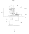
Fig. 2 is a diagram depicting a configuration example inside a first housing; -
Fig. 3 is a diagram depicting a configuration example of an observation unit; -
Fig. 4 is a diagram depicting a functional configuration example of the culture observation apparatus; -
Fig. 5 is a flow chart depicting the observation processing; -
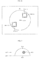
Fig. 6 is a diagram depicting culture medium drops in a culture container to be an observation target; -
Fig. 7 is a diagram depicting a culture medium drop and a fertilized embryo; -
Fig. 8 is a diagram depicting an AF area; -
Fig. 9 is a diagram depicting an AF area; -
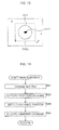
Fig. 10 is a diagram depicting tiling; -
Fig. 11 is a flow chart depicting a coarse scanning processing; -
Fig. 12 is a diagram depicting an AF area; and -
Fig. 13 is a flow chart depicting the main scanning processing. - Embodiments of the present invention will now be described with reference to the drawings.
-
Fig. 1 is a front view depicting a general configuration of a culture observation apparatus to which the present invention is applied. InFig. 1 , the solid line indicates a structure of a portion which can be seen from the outside, and a broken line indicates a structure of an internal portion which cannot be seen from the outside. - The
culture observation apparatus 11 is comprised of afirst housing 21 for culturing a fertilized embryo to be an observation target, and asecond housing 22 constituting the focus control apparatus, and thefirst housing 21 is used in a state of being placed on top of thesecond housing 22. - A
thermostatic chamber 31 covered with a heat insulating material is created inside thefirst housing 21, and thethermostatic chamber 31 is connected with the outside via afront door 32 disposed on a front face of thefirst housing 21 and atransporting port 33, which is disposed on the left side face when viewed from the front of thefirst housing 21. Astocker 34 for holding a culture container, which is not illustrated, where the fertilized embryo is placed, and acontainer transporting mechanism 35 for transporting the culture container, are disposed in thethermostatic chamber 31 of thefirst housing 21. - In the
second housing 22, adisplay unit 36 for displaying an observation image obtained by imaging a fertilized embryo in the culture container, for example, is displayed, and acontrol unit 38 for controlling the entireculture observation apparatus 11, and anobservation unit 37 for observing the fertilized embryo and imaging the observation image are disposed. - The
display unit 36 is disposed on the front side surface of thesecond housing 22, and is constituted by a liquid crystal display, for example. Theobservation unit 37 is constituted by a microscope, for example, and is secured such that a part of the unit protrudes into thethermostatic chamber 31. - As
Fig. 2 shows, the observer can place aculture container 61 on astocker 34, or remove aculture container 61 from thestocker 34 by opening thefront door 32. There are a plurality of racks in thestocker 34, and one or a plurality of culture container(s) 61 can be stored in each rack. Here aculture container 61 is a dish, for example, in which an observation target fertilized embryo is placed. - A
stage 62, on which aculture container 61 is placed, is disposed in theobservation unit 37, and thestage 62 is positioned near thecontainer transporting mechanism 35 in thethermostatic chamber 31. Thecontainer transporting mechanism 35 transports a specifiedculture container 61 from thestocker 34 onto thestage 62, or transports aculture container 61 on thestage 62 onto a predetermined rack of thestocker 34 according to the control of thecontrol unit 38. -
Fig. 3 shows a more detailed configuration of theobservation unit 37 inFig. 2 . - As illustrated, the
observation unit 37 is comprised of amain unit 91, astage 62 and anarm 92, and thestage 62 and thearm 92 are disposed above themain unit 91 inFig. 3 . In theobservation unit 37, thestage 62 and thearm 92 are disposed in thethermostatic chamber 31 of thefirst housing 21, and themain unit 91 is disposed in thesecond housing 22. - The
stage 62 is constituted by a translucent material, and as shown in the figure moves in the vertical direction (hereafter z direction) and directions perpendicular to the z direction (hereafter xy directions) according to the control of thecontrol unit 38. - The
arm 92 has a surface facing the surface of thestage 62, and afirst illumination unit 101 and acontainer observation unit 102 are disposed on thearm 92 at positions facing thestage 62. - The
first illumination unit 101 comprises a light source which emits illumination light to illuminate a fertilized embryo to be observed, and an illumination optical system for irradiating the illumination light from the light source onto theculture container 61 on thestage 62, and as shown in the figure the illumination light is irradiated onto theculture container 61 from the top. Thefirst illumination unit 101 is used when the phase contrast observation is performed on the fertilized embryo in theculture container 61. - The
container observation unit 102 comprises an image optical system which forms an image of light which entered from theculture container 61 on thestage 62, and a camera which captures an observation image of a fertilized embryo as a subject, by receiving the light collected by the image optical system, and performing photoelectric conversion. Thecontainer observation unit 102 is used when the fertilized embryo is observed using the bright field observation. - A
microscopic observation unit 103, which faces thefirst illumination unit 101, and asecond illumination unit 104, which faces thecontainer observation unit 102, are disposed in themain unit 91. Themicroscopic observation unit 103 is used for phase contrast observation of the fertilized embryo, and thesecond illumination unit 104 is used for bright field observation of the fertilized embryo. - A plurality of objective lenses 121-1 to 121-3, having a different optical magnification from one another, and a plurality of intermediate zoom lenses 122-1 to 122-3, are disposed in the
microscopic observation unit 103. - The objective lens 121-1 and the intermediate zoom lens 122-1 are disposed on the optical path of the illumination light from the first illumination unit 101 (hereafter called "phase contrast observation optical path") when the fertilized embryo is observed at x2 magnification. When the fertilized embryo is observed at x4 magnification, the objective lens 121-2 and the intermediate zoom lens 122-2 are disposed on the phase contrast observation optical path, and when the fertilized embryo is observed at x10 magnification, the objective lens 121-3 and the intermediate zoom lens 122-3 are disposed on the phase contrast observation optical path.
- In other words, when the fertilized embryo is observed using the phase contrast observation, one combination out of the objective lens 121-1 and the intermediate zoom lens 122-1, the objective lens 121-2 and the intermediate zoom lens 122-2, and the objective lens 121-3 and the intermediate zoom lens 122-3, is disposed on the phase contrast observation optical path, according to the observation magnification.
- If it is not necessary to distinguish the object lenses 121-1 to 121-3 from one another, then these objective lenses may be simply referred to as "objective lens 121", and if it is not necessary to distinguish the intermediate zoom lenses 122-1 to 122-3 from one another, then these intermediate zoom lenses may be simply referred to as "intermediate zoom lens 122".
- Under the objective lens 121 and the intermediate zoom lens 122 in the
microscopic unit 103, an imageoptical system 123 and acamera 124 are disposed as illustrated. The imageoptical system 123 collects illumination light which entered from the intermediate zoom lens 122, and guides the illumination light into thecamera 124, and thecamera 124 receives the illumination light which entered from the imageoptical system 123 and performs photoelectric conversion, so as to capture an observation image of the fertilized embryo as the subject. - Therefore in the case of the phase contrast observation of the fertilized embryo, the illumination light from the
first illumination unit 101 is irradiated onto theculture container 61 on thestage 62, and the illumination light transmitted through theculture container 61 passes through the objective lens 121 and the imageoptical system 123, and is received by thecamera 124. - The
second illumination unit 104 of themain unit 91 comprises: a light source for emitting illumination light, and an illumination optical system for irradiating the illumination light from the light source onto theculture container 61 on thestage 62. Thesecond illumination unit 104 is used for performing the bright field observation on theentire culture container 61 of the fertilized embryo. In other words, in order to perform the bright field observation for theentire culture container 61 of the fertilized embryo, the illumination light from thesecond illumination unit 104 is irradiated onto theculture container 61 on thestage 62, and the illumination light transmitted through theculture container 61 is received by thecontainer observation unit 102. -
Fig. 4 is a diagram depicting a functional configuration example of theculture observation apparatus 11. InFig. 4 , a composing element the same as that inFig. 2 orFig. 3 is denoted with a same reference numeral, for which description is omitted unless necessary. - In the example in
Fig. 4 , thestage 62, thefirst illumination unit 101 to thesecond illumination unit 104, thedisplay unit 36, thecontainer transporting mechanism 35 and thetouch panel 151 are connected to thecontrol unit 38. Thetouch panel 151 is superposed on the display screen of thedisplay unit 36, and detects the contact of the observer on the display screen, thetouch panel 151 to be more precise, of thedisplay unit 36, and supplies a signal to indicate the contact position to thecontrol unit 38. For example, the observer can perform input operation by touching thetouch panel 151, and instruct the execution of various processings through this input operation. - Based on a signal supplied from the
touch panel 151, thecontrol unit 38 displays an observation image on thedisplay unit 36, or controls operation of theobservation unit 37 and thecontainer transporting mechanism 35. Thecontrol unit 38 has anarea setting unit 161, anobservation control unit 162, a focalposition detection unit 163, a macroimage generation unit 164 and arecording unit 165. - The
area setting unit 161 sets an AF (Auto Focus) area for detecting a focusing position of the objective lens 121 to focus on a subject to be an observation target, that is, a position of the objective lens 121 when the focal position of the objective lens 121 is located at the subject. - In other words, the AF area is an area used for detecting a focusing position by auto focus control, out of the area on the
culture container 61, and the AF area may have the same size and the same shape as the observation field of view of the objective lens 121, or may be a smaller area than the observation field of view of the objective lens 121. For example, if the AF area has a same shape and a same area as the observation field of view of the objective lens 121, the entire observation image that was captured becomes the AF area, and if the AF area is smaller than the observation field of view of the objective lens 121, a predetermined area of the observation image is set as the AF area. - The
observation control unit 162 controls operation of each component of theobservation unit 37 and thecontainer transporting mechanism 35. The focalposition detection unit 163 detects a focusing position of the objective lens 121 on the subject based on the AF area which is set by thearea setting unit 161 and the captured observation image. - The focusing position of the objective lens 121 on the subject in this case refers to a relative position of the objective lens 121 with respect to the
stage 62 in the z direction (optical axis direction of the objective lens 121) when the focal point (focal plane) of the objective lens 121 is located on the subject (e.g. fertilized embryo). In theculture observation apparatus 11, the objective lens 121 is fixed, and thestage 62 moves in the z direction, hence the focusing position of the objective lens 121 is represented by a position of thestage 62 in the z direction (z coordinate) when the focal point of the objective lens 121 is positioned on the subject, for example. - If the
culture observation apparatus 11 has a configuration for the objective lens 121 to move with respect to the fixedstate 62, the focusing position of the objective lens 121 can be the position in the z direction of the objective lens 121 itself. - As a macro image, the macro
image generation unit 164 generates one image in which theentire culture container 61 is displayed, out of the plurality of observation images obtained by imaging different positions of theculture container 61. Therecording unit 165 is constituted by a nonvolatile memory, for example, and records programs which thecontrol unit 38 executes, various data and observation images. A macro image is also recorded in therecording unit 165, but instead of the macro image, each of a plurality of observation images obtained by imaging different positions of theculture container 61 may be directly recorded in therecording unit 165. In other words, each of the plurality of observation images constituting a macro image may be recorded. - If the observer operates the
touch panel 151 and starts observing a fertilized embryo in aculture container 61 stored in a predetermined rack of thestocker 34, thecontrol unit 38 moves theculture container 61 specified by the observer onto thestage 62. In other words, theobservation control unit 162 controls thecontainer transporting mechanism 35 according to the signal from thetouch panel 151, and thecontainer transporting mechanism 35 transports theculture container 61 stored in thestocker 34 according to this control, and places it on thestage 62. - If the
culture container 61 specified by the observer is placed on thestage 62, theculture observation apparatus 11 starts the observation processing to observe the fertilized embryo in theculture container 61. Now the observation processing will be described with reference to the flow chart inFig. 5 . - In step S11, the
container observation unit 102 captures an image of theentire culture container 61 on thestage 62. - In other words, the
observation control unit 162 controls thestage 62 and moves thestage 62 so that theculture container 61 on thestage 62 is placed on the optical path of the illumination light from thesecond illumination unit 104. Then theobservation control unit 162 irradiates the illumination light on thesecond illumination unit 104, and causes thecontainer observation unit 102 to capture an observation image of theentire culture container 61 as the subject. If the observation image is captured, thecontrol unit 38 obtains the observation image from thecontainer observation unit 102, supplies it to thedisplay unit 36, and displays the observation image. - In step S12, the
control unit 38 accepts the specification on a detection area including a subject to be observed, in the observation image displayed on thedisplay unit 36. - In other words, if the observation image is displayed on the
display unit 36, the observer performs input operation on the display screen of thedisplay unit 36, and specifies an area which is on the displayed observation image, and which includes the subject to be observed, as the detection area. Thecontrol unit 38 selects the area specified by the observer as the detection area, based on the signal from thetouch panel 151. - For example, it is assumed that some culture medium drops containing a fertilized embryo to be observed are located in the bottom of the
culture container 61, and theculture container 61 is filled with a colorless and transparent mineral oil. And it is assumed that the observation image shown inFig. 6 is displayed on thedisplay unit 36 as the observation image captured by thecontainer observation unit 102 in this case. - In the example in
Fig. 6 , acircular culture container 61 is displayed at the center of the observation image, and the position indicated by the arrow C11 is a center position on the bottom of the culture container 61 (hereafter called "center position C11"). Two culture medium drops D11-1 and D11-2 are formed in theculture container 61. - In
Fig. 6 , the culture medium drop D11-1 is located in an upper right direction when viewed from the center position C11, and the culture medium drop D11-2 is located in the lower left direction when viewed from the center position C11. The observer specifies the detection areas, for example, to an area R11-1 which is around the culture medium drop D11-1 and includes the entire culture medium drop D11-1, and an area R11-2, which is around the culture medium drop D11-2 and includes the entire culture medium drop D11-2. - Hereafter, the culture medium drop D11-1 and the culture drop D11-2 may be simply called "culture medium drop D11", when clear distinction is not required, and the area R11-1 and the area R11-2 may be simply called "area R11" when clear distinction is not required.
- The culture medium drop D11 formed in the
culture container 61 has a certain thickness in the z direction, as shown inFig. 7 , for example. InFig. 7 , the vertical direction indicates the z direction, that is, the optical axis direction of the objective lens in acontainer observation unit 102 and the objective lens 121. - In the example in
Fig. 7 , a hemispherical culture medium drop D11 is formed on the bottom B11 of theculture container 61, and one fertilized embryo H11 to be observed is floating in the culture medium drop D11. The culture medium drop D11 does not move with respect to the bottom B11, but the fertilized embryo H11 moves in any direction in the culture medium drop D11. - Therefore in the
culture observation apparatus 11, when the focusing position of the objective lens 121 on the fertilized embryo H11 is detected, the focusing position of the objective lens 121 on the culture medium drop D11 is detected first by auto focus control. In other words, a position of thestage 62 in the z direction, by which the position of the focal point of the objective lens 121 in the z direction comes to a boundary between the boundary portion (edge portion) of the culture medium drop D11 and the bottom B12 of theculture container 61 indicated by arrow A11, is detected. - Then by auto focus control based on the focusing position on the culture medium drop D11, a position of the
stage 62 in the z direction, by which the focusing position of the objective lens 121 on the fertilized embryo H11, that is, the position of the focal point of the objective lens 121 in the z direction, comes to the center of the fertilized embryo H11 indicated by the arrow A12, is detected. - Compared with detecting a focusing position on the moving fertilized embryo H11, detecting a focusing position on the culture medium drop D11, which does not move, is relatively easier, and if the focusing position on the fertilized embryo H11 is detected, based on the focusing position on the culture medium drop D11, the focusing position on the fertilized embryo H11 can be detected with more certainty.
- The fertilized embryo H11 floats in the culture medium drop D11, but is often located near the bottom B11 of the
culture container 61 in the culture medium drop D11. Therefore if the focusing position on the culture medium drop D11, that is, as shown in the figure, the bottom B11, is used as a reference and the detection target is limited to the predetermined distance range upward from the bottom B11, then the focusing position on the fertilized embryo H11 can be detected with more certainty than the case of detecting the focusing position on the fertilized embryo H11 without setting any reference position, as is the case of the prior art. - Hereafter, the boundary portion between the boundary (surface) portion of the culture medium drop D11 and the bottom B11 of the
culture container 61, that is, a portion where the hemispherical surface of the culture medium drop D11 and the bottom B11 meet inFig. 7 , is called "edge portion of the culture medium drop D11". - Referring back to the flow chart in
Fig. 5 , when the observer specifies areas R11 in the observation image as the detection areas, thecontrol unit 38 selects one of the specified detection areas as the processing target detection area. - In step S13, the
area setting unit 161 of thecontrol unit 38 sets an AF area for the culture medium drop in the processing target detection area. - If the culture medium drop D11 in the processing target detection area is on the right side of the center position C11 in
Fig. 6 , for example, thearea setting unit 161 sets an area having a predetermined size, of which center is the center position of the left hand side of the rectangular area R11 selected as the detected area, as the AF area. - The size of the AF area is set to a size by which the edge portion of the culture medium drop D11 is included in the AF area. The edge portion of the culture medium drop D11 must be included in the AF area here because the focusing position is detected based on the contrast intensity of the edge portion.
- In concrete terms, if the area R11-1 in
Fig. 6 is selected as a processing target detection area, an area R21-1 having a predetermined size, of which center is the center position C21-1 of the left hand side of the area R11-1, as shown inFig. 8 , is selected as the AF area. The area R21-1 includes the left side edge portion of the culture medium drop D11-2, as shown inFig. 8 . - If the culture medium drop D11 in the processing target detection area is on the left side of the center position C11 in
Fig. 6 , for example, thearea setting unit 161 sets an area having a predetermined size, of which center is the center position of the right hand side of the rectangular area R11 selected as the detection area, as the AF area. The size of the AF area is set to a size by which the edge portion of the culture medium drop D11 is included in the AF area. - In concrete terms, if the area R12-2 in
Fig. 6 is selected as a processing target detection area, an area R21-2 having a predetermined size, of which center is the center position C21-2 of the right hand side of the area R11-2, as shown inFig. 9 , is selected as the AF area. The area R21-2 includes the right side edge portion of the culture medium drop D11-2, as shown inFig. 9 . - Hereafter the position C21-1 and the position C21-2 may be simply called "position C21" when a clear distinction is not required, and the area R21-1 and the area R21-2 may be simply called "area R21" when clear distinction is not required.
- By setting the position C21, on the boundary on the center position C11 side of the area R11 selected as the detection area, to the center, and selecting the area R21 which includes the edge portion of the culture medium drop D11 as the AF area, as described above, the focusing position on the culture medium drop D11 can be detected more easily and with certainty.
- For example, the focusing position is normally detected by capturing a plurality of observation images while changing the distance from the objective lens 121 to the
stage 62, and detecting an observation image of which contrast intensity is highest, out of those observation images. In other words, a position of the objective lens 121, when an observation image having the highest contrast intensity is captured, is regarded as the focusing position of the objective lens 121 on the subject. - In an area near the edge of the
culture container 61, that is, in an area near the side wall face of theculture container 61, illumination unevenness, that is brightness unevenness, is generated since the illumination light irradiated onto theculture container 61 is eclipsed by the side wall face. If such illumination unevenness is generated, contrast is changed by the illumination unevenness, hence if an area including the illumination unevenness is used as an AF area, error occurs in detecting a focusing position of the objective lens 121 on the subject, and accuracy to detect the focusing position drops. - Therefore the
culture observation apparatus 11 selects an area on the center position C11 side of theculture container 61 when viewed from the culture medium drop D11, as an AF area so that the area which causes a detection error is not included in the AF area. As a result, a focusing position on the subject (culture medium drop D11) can be detected more easily and with certainty. - An area to be selected as the AF area can be any area which includes the edge portion of the culture medium drop D11, and which does not generate illumination unevenness.
- Therefore if illumination unevenness is generated only in an area which is within a predetermined distance L from the side wall face of the
culture container 61, for example, an area, which does not include the area within the distance L from the side wall face of theculture container 61 and which includes the edge portion of the culture medium drop D11, is selected as the AF area. - Referring back to the flow chart in
Fig. 5 , when the AF area is set, theobservation control unit 162 controls themicroscopic observation unit 103, and moves the objective lens 121-1 and the intermediate zoom lens 122-1 so that the objective lens 121-1 and the intermediate zoom lens 122-1 are disposed on the phase contrast observation optical path. - The
observation control unit 162 also controls thestage 62 and moves thestage 62 so that theculture container 61 on thestage 62 is disposed on the phase contrast observation optical path. To be more specific, theobservation control unit 162 moves thestage 62 so that the center position of the AF area, determined with respect to the detection area to be the processing target, comes to a position on the phase contrast observation optical path. In this case, the entire observation field of view of the objective lens 121 becomes the AF area. In other words, the entire observation image becomes the AF area. - Then the
observation control unit 162 controls thefirst illumination unit 101 and irradiates the illumination light onto theculture container 61. Thereby the phase contrast observation on theculture container 61 becomes possible at x2 optical magnification. - In step S14, the
observation control unit 162 causes thecamera 124 to capture the observation image at each position of thestage 62, while moving thestage 62 in the z direction. In other words, the illumination light irradiated from thefirst illumination unit 101 onto the AF area of theculture container 61 transmits through the AF area (e.g. culture medium drop), and enters the objective lens 121-1. - The illumination light which entered the objective lens 121-1 is collected by the objective lens 121-1, and enters the
camera 124 via the intermediate zoom lens 122-1 and the imageoptical system 123. Thecamera 124 performs photoelectric conversion on the illumination light which entered from the imageoptical system 123 along with the movement of thestage 62, so as to capture observation images of the area which includes the AF area. - Since an observation image in each state, when the
stage 62 is located at each position in the z direction, is obtained like this, thecontrol unit 38 obtains a plurality of observation images captured by thecamera 124. - In step S15, the focal point
position detection unit 163 detects a focusing position of the objective lens 121-1 on the culture medium drop (hereafter especially called "boundary focusing position"), based on the plurality of observation images obtained by thecamera 124. In other words, the focal pointposition detection unit 163 determines the contrast intensity of each of the plurality of observation images, and regards the position of thestage 62 in the z direction, when the observation image having the highest contrast intensity was captured, as the boundary focusing position. - The boundary focusing position detected like this is a position of the
stage 62 when the focal position of the object lens 121-1 is at a boundary between the edge portion of the culture medium drop and the bottom of theculture container 61. - When an observation image for detecting the boundary focusing position is captured, it is preferable to use a high NA (Numerical Aperture) optical system of which depth of focus is small, so that the edge portion of the culture medium drop can be accurately detected.
- In step S16, the
observation control unit 162 performs tiling. In other words, theobservation control unit 162 controls themicroscopic observation unit 103, and moves the objective lens 121-2 and the intermediate zoom lens 122-2 so that the objective lens 121-2 and the intermediate zoom lens 122-2 are disposed on the phase contrast observation optical path. Thereby the phase contrast observation on theculture container 61 becomes possible at x4 optical magnification. - To be more specific, when the objective lens 121 is switched, the
stage 62 is moved based on the control of theobservation control unit 162, so that the focal position of the objective lens 121-2 after switching becomes the boundary position between the edge portion of the culture medium drop and the bottom of theculture container 61. - Then the
observation control unit 162 causes thecamera 124 to capture an observation image at each position of thestage 62, while moving thestage 62 in the xy directions, so that all the areas of the processing target detection area is captured by a plurality of times of image capturing. - In this way the entire area R11, which was selected as the detection area, is captured by a plurality of times of image capturing, as shown in
Fig. 10 , for example. InFig. 10 , one square, such as the area RS11, indicates an area included in the observation image obtained by one image capturing. - In the case of the example in
Fig. 10 , the entire area R11 was imaged by a total of twenty five times of image capturing (five times in the vertical direction, and five times in the horizontal direction). Each observation image has portions that overlap with adjacent observation images. In other words, in the detection area, an area near the edges of one area imaged as an observation image, is also included in an area imaged as another observation image. - After an observation image of each area in the detection area is captured like this, the
control unit 38 obtains this plurality of images from thecamera 124. - In step S17, the macro
image generation unit 164 specifies a position of the fertilized embryo (hereafter called "fertilized embryo position") in the detection area based on the observation image of each area of the detection area obtained by tiling. For example, for each observation image, the macroimage generation unit 164 determines a shape and size of an object included in the observation image, and determines whether this object is the fertilized embryo or not, whereby the fertilized embryo position in the detection area is specified. - For example, in the case of the example in
Fig. 10 , the fertilized embryo H11 exists in the area RS11 in the area R11 selected as the detection area, hence the fertilized embryo H12 is detected in the observation image of the area RS11, and the position of the fertilized embryo H11 is regarded as the fertilized embryo position. - In step S18, the macro
image generation unit 164 generates one image by arranging each of the plurality of observation images obtained by tiling, so as to be the same positional relationship as the areas of the subject captured in these observation images, and regards this image as the macro image. In other words, a macro image is an image of the entire detection area generated by arranging and merging a plurality of observation images. - When observation images for generating a macro image are captured, it is preferable to use a low NA optical system, of which depth of focus is large, in order to decrease the focal shift on the entire detection area, particularly on the fertilized embryo.
- In step S19, the
culture observation apparatus 11 performs coarse scanning, and detects a general focusing position on the fertilized embryo in the processing target detection area. For example, in the coarse scanning processing, the area centering around the fertilized embryo position is selected as the AF area, and auto focus control is performed based on the focusing position on the culture medium drop. The coarse scanning processing will be described in detail later. - In step S20, the
culture observation apparatus 11 performs the main scanning processing, and detects a more accurate focusing position on the fertilized embryo in the processing target detection area. For example, in the main scanning processing, an area centered around the fertilized embryo position is selected as the AF area, and auto focus control is performed based on the focusing position obtained in the coarse scanning processing. In the main scanning processing, an observation image at each position in the z direction of thestage 62 is captured, and these observation images, the fertilized embryo position, the focusing position of the objective lens 121 on the fertilized embryo, and the macro image are recorded in therecording unit 165. The main scanning processing will be described in detail later. - In step S21, the
control unit 38 supplies the observation image, which was captured when the stage 62 (objective lens 121) is positioned in the finally determined focusing position of the objective lens 121 on the fertilized embryo, to thedisplay unit 36, and causes thedisplay unit 36 to display the observation image. - In step S22, the
control unit 38 determines whether processing is ended or not. For example, it is determined that the processing is ended if all the plurality of detection areas, specified by the observer, become the processing targets, and the focusing position is detected. - If it is determined that the processing is not ended in step S22, the next detection area which has not yet been selected becomes the processing target, processing returns to step S13, and the above mentioned processing is repeated.
- If it is determined that the processing is ended in step S22, on the other hand, the
container transporting mechanism 35 transports theculture container 61 on thestage 62 to a rack of thestocker 34, according to the control of theobservation control unit 162, and the observation processing ends. - As described above, the
culture observation apparatus 11 selects an area, which includes an edge portion of the culture medium drop in theculture container 61 and has no illumination unevenness, as the AF area, and detects a boundary focusing position of the culture medium drop in the AF area as a detection target. Then theculture observation apparatus 11 detects a focusing position on the fertilized embryo, based on the boundary focusing position. - By detecting the boundary focusing position with selecting an area which includes an edge portion of the culture medium drop and has no illumination unevenness as the AF area in this way, the boundary focusing position of the objective lens 121 on the culture medium drop can be detected more simply and with certainty. If the focusing position on the fertilized embryo position is detected based on this boundary focusing position, the final focusing position on the fertilized embryo can be detected more simply and with certainty.
- The coarse scanning processing corresponding to the processing in step S19 in
Fig. 5 will now be described with reference to the flow chart inFig. 11 . - In step S51, the
observation control unit 162 changes the optical magnification to observe theculture container 61 in theobservation unit 37. - In other words, the
observation control unit 162 controls themicroscopic observation unit 103 and moves the objective lens 121-3 and the intermediate zoom lens 122-3 so that the objective lens 121-3 and the intermediate zoom lens 122-3 are disposed on the phase contrast observation optical path. - The
observation control unit 162 also changes the setting of thecamera 124 so that the resolution of the observation image is decreased by binning, and controls thefirst illumination unit 101, to irradiate the illumination light onto theculture container 61. Thereby the phase contrast observation for theculture container 61 becomes possible at x10 optical magnification. The optical magnification need not be x10 if the fertilized embryo is included in the entire observation image, and can be a magnification which the observer specified in advance, for example. - Then the
observation control unit 162 controls thestage 62 and moves thestage 62 in the xy directions so that the fertilized embryo position specified in step S17 inFig. 5 is located on the phase contrast observation optical path. At the same time, theobservation control unit 162 controls thestage 62, and moves thestage 62 so that the position of thestage 62 in the z direction comes to the boundary focusing position detected in step S15 inFig. 5 . - As a result, the focal position of the objective lens 121 in the xy directions becomes the same as the position of the fertilized embryo, and the position [of the focal position of the objective lens 121] in the z direction comes to the position on the boundary surface between the culture medium drop and the bottom of the
culture container 61. Therefore if the stage 62 (objective lens 121) is moved in the z direction in this state, the fertilized embryo can be focused on. - Then the
area setting unit 161, as shown inFig. 12 , sets the AF area to an area RF11 around the culture medium drop D11, of which center is the fertilized embryo position and which includes the entire culture medium drop D11. This area RF11 is determined so that the area RF11 has a boundary in a position close to the boundary of the culture medium drop D11, and the culture medium drop D11 occupies most of the area RF11. - By selecting the area RF11 around the culture medium drop D11, which includes the entire culture medium drop D11, as the AF area like this, the focusing position on the fertilized embryo can be detected with more certainty. In other words, foreign substances exist in the
culture container 61 along with the culture medium drops D11, therefore if the AF area is too large, many foreign substances are included in the AF area, and accuracy to detect the focusing position diminishes. By selecting the area around the culture medium drop D11 as the AF area, foreign substances included in the AF area can be minimized, and the focusing position can be detected more accurately. - Referring back to the flow chart in
Fig. 11 , in step S52, theobservation control unit 162 causes thecamera 124 to capture the observation image at each position of thestage 62, while moving thestage 62 in the z direction from the boundary focusing position. In other words, the illumination light from thefirst illumination unit 101 enters thecamera 124 via theculture container 61, thestage 62, the objective lens 121-3, the intermediate zoom lens 122-3 and the imageoptical system 123, and the observation images are captured by thecamera 124. - For example, the focal position of the objective lens 121 in the z direction is moved from the position indicated by the arrow A11 in
Fig. 7 (state where thestage 62 is in the boundary focusing position) to a predetermined position above the position indicated by the arrow A12 inFig. 7 (area near the upper edge portion of the culture medium drop D11). Then an observation image is captured in each state where the objective lens 121 is located at each position in the z direction. - If the
stage 62 is moved to each position in a predetermined range in the z direction including the boundary focusing position, an observation image is captured in a state where thestage 62 is at each position, and a focusing position on the fertilized embryo is detected like this, then detection accuracy can be improved. The range of moving the stage 62 (objective lens 121) in the z direction must be a relatively wide range, sufficient to focus on the fertilized embryo without fail. - After the observation images are captured at each position in the z direction, the
control unit 38 obtains a plurality of observation images captured by thecamera 124. The captured observation image is sufficient if the AF area is included, and it is unnecessary that the observation field of view of the objective lens 121-3 and the AF area match. - Referring back to the flow chart in
Fig. 11 , in step S53, the focalposition detection unit 163 detects the focusing position of the objective lens 121-3 on the fertilized embryo, based on the plurality of observation images obtained by the camera 124 (hereafter especially called "tentative fertilized embryo focusing position"). - In other words, the focal
position detection unit 163 determines the contrast intensity in each AF area of the plurality of observation images, and regards a position of thestage 62 in the z direction, when an observation image having a maximum contrast intensity is captured, as the tentative fertilized embryo focusing position. - The tentative fertilized embryo focusing position detected like this is a position of the
stage 62 in the z direction when the focal position of the objective lens 121-3 is in the position of the fertilized embryo. In the coarse scanning processing however, only a certain degree of detection accuracy can be implemented, since observation images at low resolution are used for detection. - In step S54, the
observation control unit 162 calculates the exposure time of thecamera 124, which is set for executing the main scanning processing, using the observation image captured in a state where thestage 62 is located in the tentative fertilized embryo focusing position. For example, theobservation control unit 162 determines the brightness value of each pixel of the entire observation image, and determines the exposure time by multiplying the average value of these brightness values by a predetermined coefficient. - The exposure time calculated like this is suitable for imaging the fertilized embryo as a subject. In other words, the brightness around the fertilized embryo upon capturing an observation image greatly changes depending on the position in the culture medium drop where the fertilized embryo exists, hence the exposure time must be set appropriately.
- Here the state where the
stage 62 is in the tentative fertilized embryo focusing position is a state where the fertilized embryo is generally focused, and in the observation image captured in this state, the fertilized embryo to be the subject is at the center of the image. In other words, the observation image captured in this state is an image captured in an environment which is approximately the same as the observation image which is captured in a state where the fertilized embryo is more accurately focused in the main scanning processing. Therefore using an observation image captured in a state where the fertilized embryo is generally focused, an exposure time suitable for the image capturing environment is calculated, and imaging is performed with the calculated exposure time in the main scanning, then an observation image with more appropriate brightness can be obtained. - After the exposure time is calculated like this, the coarse scanning processing ends, and processing advances to step S20 in
Fig. 5 . - By detecting the focusing position on the fertilized embryo based on the focusing position on the culture medium drop like this in the coarse scanning processing, a general focusing position on the fertilized embryo can be obtained with more certainty. Furthermore only the area around the fertilized embryo is used as the AF area, hence the accuracy to detect the focusing position can be increased even more.
- Now the main scanning processing corresponding to the processing in step S20 in
Fig. 5 will be described with reference to the flow chart inFig. 13 . - In step S81, the
observation control unit 162 changes the setting for observing theculture container 61 in theobservation unit 37. In other words, theobservation control unit 162 changes the setting of thecamera 124, so that the exposure time of thecamera 124 is changed to the exposure time calculated in the processing in step S54 inFig. 11 , and the resolution of the observation image becomes higher than that in the coarse scanning processing. - The
observation control unit 162 also controls thefirst illumination unit 101, and irradiates the illumination light onto theculture container 61. Thereby the phase contrast observation for theculture container 61 becomes possible at x10 optical magnification. - Then the
observation control unit 162 controls thestage 62 and moves thestage 62 in the xy directions so that the fertilized embryo position specified in step S17 inFig. 5 is located on the phase contrast observation optical path. At the same time, theobservation control unit 162 controls thestage 62, and moves thestage 62 so that the position of thestage 62 in the z direction comes to the tentative fertilized embryo focusing position detected in step S53 inFig. 11 . - As a result, the focal position of the objective lens 121 becomes approximately the same as the position of the fertilized embryo. Therefore the fertilized embryo can be more accurately focused by moving the
stage 62 from this state within a relatively narrow range in the z direction, centering around the tentative fertilized embryo focusing position. - Then the
area setting unit 161 sets the AF area to an area around the culture medium drop, of which center is the fertilized embryo position and which includes the entire culture medium drop, just like the case of the coarse scanning processing. This AF area is the same area as the AF area used for the coarse scanning processing. - In step S82, the
observation control unit 162 causes thecamera 124 to capture an observation image at each position of thestage 62, while moving thestage 62 from the tentative fertilized embryo focusing position in the z direction. In other words, the illumination light from thefirst illumination unit 101 enters thecamera 124 via theculture container 61, thestage 62, the objective lens 121-3, the intermediate zoom lens 122-3 and the imageoptical system 123, and the observation image is captured by thecamera 124. - For example, the focal position of the objective lens 121 in the z direction is moved from the position indicated by the arrow A12 in
Fig. 7 to each position in the predetermined range centering around the position. Then an observation image is captured in each state where the objective lens 121 is located at each position in the z direction. In other words, thestage 62 is moved to each position in the predetermined range centering around the tentative fertilized embryo focusing position, and an observation image is captured. - If the
stage 62 is moved to each position in a predetermined range in the z direction centering around the tentative fertilized embryo position, an observation image is captured in a state where thestage 62 is at each position, and a focusing position on the fertilized embryo is detected like this, then a more accurate focusing position can be detected. - In the main scanning processing, the range of moving the objective lens 121 (stage 62) in the z direction is narrower than the range of moving the objective lens 121 in the coarse scanning processing. This is because the general focusing position on the fertilized embryo has been detected in the coarse scanning processing, and the detection target can only be an area around this focusing position.
- If the observation image at each position in the z direction is captured, the
control unit 38 obtains a plurality of observation images captured by thecamera 124. The captured observation image is sufficient if the AF area is included. - Referring back to the flow chart in
Fig. 13 , in step S83, the focalpoint detection unit 163 detects the focusing position of the objective lens 121-3 on the fertilized embryo (hereafter especially called "final fertilized embryo focusing position") based on the plurality of observation images obtained by thecamera 124. - In other words, the focal
position detection unit 163 determines the contrast intensity in each AF area of the plurality of observation images, and regards the position of thestage 62 in the z direction when an observation image having the highest contrast intensity was captured as the final fertilized embryo focusing position. - The final fertilized embryo focusing position detected like this is a position of the
stage 62 when the focal position of the objective lens 121-3 comes to the position of the fertilized embryo. In this canning processing, observation images, having higher resolution than those in the coarse scanning, are used for detection, hence the final fertilized embryo focusing position should be a more accurate focusing position than the tentative fertilized embryo focusing position. - In step S84, the
control unit 38 records the plurality of observation images captured in the main scanning processing, the final fertilized embryo focusing position, the fertilized embryo position and the macro image in therecording unit 165. To be more precise, the positions of thestage 62 in the x, y and z directions, upon capturing the observation image, are also recorded in correspondence with each observation image. - Out of the observation images recorded like this, the observation image captured in the final fertilized embryo focusing position is displayed on the
display unit 36 in step S21 inFig. 5 . After the observation images and other data are recorded in therecording unit 165, the main scanning processing ends, and processing then advances to step S21 inFig. 5 . - In the main scanning processing, the focusing position on the fertilized embryo is detected based on the tentative fertilized embryo focusing position on the fertilized embryo, whereby the accurate focusing position on the fertilized embryo can be obtained more simply and with certainty. Furthermore, only the area around the fertilized embryo is used as the AF area, hence the accuracy to detect the focusing position can be increased even more.
- In the above description, the observation processing is executed when the observer instructs a
culture container 61 and observation of theculture container 61, but once the observer instructs the detection area, the observation processing is executed with a predetermined interval, regardless the instruction of the observer. In this case, each detection area previously specified sequentially becomes a processing target, and the observation images are captured in this area. - Embodiments of the present invention are not limited to the above embodiment, but numerous modifications can be made without departing from the true spirit and scope of the invention.
-
- 11
- culture observation unit
- 37
- observation unit
- 38
- control unit
- 62
- stage
- 101
- first illumination unit
- 102
- container observation unit
- 103
- microscopic observation unit
- 104
- second illumination unit
- 151
- touch panel
- 161
- area setting unit
- 162
- observation control unit
- 163
- focal position detection unit
- 164
- macro image generation unit
- 165
- recording unit
Claims (9)
- A focus control apparatus for detecting a focusing position of an objective lens on a subject, comprising:an area setting unit that selects an area, which does not include an area located within a predetermined distance from an edge of a container placed on a stage and includes a boundary portion of the subject in the container, as a first target area which is to be a target of detecting the focusing position;an imaging control unit that changes a distance between the objective lens and the stage in a direction of an optical axis of the objective lens, and also captures a plurality of observation images on the first target area at different distances; anda focusing position detection unit that detects the focusing positions based on the plurality of observation images.
- The focus control apparatus according to Claim 1, wherein
the subject is a culture medium drop in which a fertilized embryo is included,
the area setting unit, after detecting the focusing position, selects an area near the culture medium drop including the entire culture medium drop as a second target area which is to be a target of detection of the focusing position on the fertilized embryo,
the imaging control unit changes the distance from the state where the objective lens is in the focusing position on the subject and captures a plurality of observation images of the second target area at different distances, and
the focusing position detection unit detects a focusing position of the objective lens on the fertilized embryo based on the plurality of observation images of the second target area. - The focus control apparatus according to Claim 1, wherein the first target area is an area which includes a boundary portion of the subject located on the container center side.
- The focus control apparatus according to Claim 1, wherein the area setting unit selects a predetermined size area centering around a point on the boundary of the pre-specified detection area including the subject, as the first target area.
- The focus control apparatus according to Claim 1, wherein
the focusing position detection unit detects, out of the plurality of observation images, an observation image of which contrast intensity is the highest, and selects, as the focusing position, a relative position with respect to the stage of the objective lens when the detected observation image is captured. - A culture observation apparatus for observing a fertilized embryo in a culture medium drop and culturing the fertilized embryo, comprising:an area setting unit that sets an area which includes an edge of the culture medium drop in a culture container as a detection area;a focusing position detection unit that detects a focusing position in the detection area;a specifying unit that obtains an observation image by imaging the culture medium drop based on the focusing position detected by the focusing position detection unit and specifies a position of the fertilized embryo in the culture medium drop based on the observation image; andan observation control unit that observes the fertilized embryo based on the position of the fertilized embryo.
- The culture observation apparatus according to Claim 6, wherein the detection area which is set by the area setting unit is limited to an area including only a part of an edge of the culture medium drop, and is set to a partial area of the edge located distant from a side wall of the culture container.
- The culture observation apparatus according to Claim 6, wherein the observation control unit controls an imaging magnification when the fertilized embryo is observed so that the magnification becomes higher than the magnification used for imaging by the specifying unit.
- The culture observation apparatus according to Claim 6, wherein the specifying unit images the culture medium drop, with this culture medium drop having been divided into a plurality of sections, and creates one observation image by merging the plurality of observation images.
Applications Claiming Priority (2)
| Application Number | Priority Date | Filing Date | Title |
|---|---|---|---|
| JP2009113396 | 2009-05-08 | ||
| PCT/JP2010/057789 WO2010128670A1 (en) | 2009-05-08 | 2010-05-07 | Focus control device, and incubation and observation device |
Publications (2)
| Publication Number | Publication Date |
|---|---|
| EP2447752A1 true EP2447752A1 (en) | 2012-05-02 |
| EP2447752A4 EP2447752A4 (en) | 2018-07-04 |
Family
ID=43050167
Family Applications (1)
| Application Number | Title | Priority Date | Filing Date |
|---|---|---|---|
| EP10772187.0A Withdrawn EP2447752A4 (en) | 2009-05-08 | 2010-05-07 | Focus control device, and incubation and observation device |
Country Status (4)
| Country | Link |
|---|---|
| US (1) | US8917347B2 (en) |
| EP (1) | EP2447752A4 (en) |
| JP (1) | JP5633753B2 (en) |
| WO (1) | WO2010128670A1 (en) |
Families Citing this family (16)
| Publication number | Priority date | Publication date | Assignee | Title |
|---|---|---|---|---|
| CN103210338A (en) * | 2010-08-30 | 2013-07-17 | 三洋电机株式会社 | Observation device, observation program and observation system |
| JP5893412B2 (en) * | 2012-01-13 | 2016-03-23 | キヤノン株式会社 | Imaging apparatus and control method thereof |
| JP6147006B2 (en) * | 2013-01-09 | 2017-06-14 | オリンパス株式会社 | Imaging apparatus, microscope system, and imaging method |
| JP6595156B2 (en) | 2014-03-04 | 2019-10-23 | 富士フイルム株式会社 | Cell image acquisition apparatus and method, and program |
| JP6173950B2 (en) | 2014-03-04 | 2017-08-02 | 富士フイルム株式会社 | Cell imaging control apparatus and method, and program |
| JP6293186B2 (en) * | 2016-03-10 | 2018-03-14 | 株式会社Screenホールディングス | Imaging arrangement determining method in imaging apparatus and imaging apparatus |
| EP3480291A4 (en) * | 2016-07-01 | 2019-07-03 | Sony Corporation | IMAGE ACQUISITION METHOD, IMAGE ACQUISITION DEVICE, PROGRAM, AND CULTURE CONTAINER |
| JP6667411B2 (en) | 2016-09-30 | 2020-03-18 | 富士フイルム株式会社 | Observation device and method, and observation device control program |
| WO2019065144A1 (en) | 2017-09-29 | 2019-04-04 | 富士フイルム株式会社 | Observation device, observation method, and observation program |
| CN113260894B (en) * | 2018-12-28 | 2023-04-04 | 仪景通株式会社 | Microscope system |
| TWI692969B (en) * | 2019-01-15 | 2020-05-01 | 沅聖科技股份有限公司 | Camera automatic focusing method and device thereof |
| US11543639B2 (en) * | 2019-01-29 | 2023-01-03 | Li-Cor, Inc. | Macro-micro telecentric scanning systems and methods |
| WO2022056374A1 (en) | 2020-09-11 | 2022-03-17 | The Brigham And Women's Hospital, Inc. | Automated aneuploidy screening using arbitrated ensembles |
| TWI792582B (en) * | 2021-09-27 | 2023-02-11 | 海華科技股份有限公司 | Lens focusing system, lens focusing method and chart display structure |
| JP2024059329A (en) * | 2022-10-18 | 2024-05-01 | 株式会社エビデント | Microscope System |
| CN116223368B (en) * | 2022-12-12 | 2025-12-12 | 北京航空航天大学 | Systems and methods for rapid localization and observation of embryos in culture dishes |
Family Cites Families (22)
| Publication number | Priority date | Publication date | Assignee | Title |
|---|---|---|---|---|
| JPS562565A (en) * | 1979-06-21 | 1981-01-12 | Olympus Optical Co Ltd | Deciding method for particle coagulation pattern |
| JPH0698584B2 (en) * | 1989-11-24 | 1994-12-07 | 俊郎 樋口 | Micro mover for micro manipulator |
| US5398096A (en) | 1992-06-15 | 1995-03-14 | Minolta Co., Ltd. | Automated focus point control device |
| JPH05346537A (en) * | 1992-06-15 | 1993-12-27 | Minolta Camera Co Ltd | Automatic focus control device |
| JPH0698232A (en) * | 1992-09-10 | 1994-04-08 | Canon Inc | Image recognition device and imaging device |
| US6416959B1 (en) * | 1997-02-27 | 2002-07-09 | Kenneth Giuliano | System for cell-based screening |
| JPH1173903A (en) * | 1997-08-28 | 1999-03-16 | Jeol Ltd | Autofocus method for scanning electron microscope |
| US7034883B1 (en) * | 1999-08-10 | 2006-04-25 | Cellavision Ab | Automatic focusing |
| US6798571B2 (en) * | 2001-01-11 | 2004-09-28 | Interscope Technologies, Inc. | System for microscopic digital montage imaging using a pulse light illumination system |
| JP4578814B2 (en) * | 2004-01-26 | 2010-11-10 | 晴夫 高林 | Automatic search and recovery device for target objects |
| JP2006003653A (en) * | 2004-06-17 | 2006-01-05 | Olympus Corp | Biological sample observating system |
| JP2006309088A (en) * | 2005-05-02 | 2006-11-09 | Research Organization Of Information & Systems | Microscope focusing position high-precision measurement method |
| US7417213B2 (en) * | 2005-06-22 | 2008-08-26 | Tripath Imaging, Inc. | Apparatus and method for rapid microscopic image focusing having a movable objective |
| JP4730000B2 (en) | 2005-07-01 | 2011-07-20 | 株式会社ニコン | incubator |
| JP4182117B2 (en) * | 2006-05-10 | 2008-11-19 | キヤノン株式会社 | IMAGING DEVICE, ITS CONTROL METHOD, PROGRAM, AND STORAGE MEDIUM |
| CN101438147B (en) * | 2006-05-31 | 2011-09-28 | 奥林巴斯株式会社 | Biological specimen imaging method and biological specimen imaging apparatus |
| JPWO2007145091A1 (en) | 2006-06-15 | 2009-10-29 | 株式会社ニコン | Cell culture equipment |
| WO2008007725A1 (en) * | 2006-07-12 | 2008-01-17 | Toyo Boseki Kabushiki Kaisha | Analyzer and use thereof |
| JP4973162B2 (en) | 2006-12-01 | 2012-07-11 | 株式会社ニコン | Image processing apparatus, image processing program, and observation system |
| JP4873729B2 (en) * | 2007-04-06 | 2012-02-08 | キヤノン株式会社 | Optical equipment |
| JP4370535B2 (en) * | 2007-06-28 | 2009-11-25 | ソニー株式会社 | Image display device, imaging device, image display control method, and program |
| US8878923B2 (en) * | 2007-08-23 | 2014-11-04 | General Electric Company | System and method for enhanced predictive autofocusing |
-
2010
- 2010-05-07 WO PCT/JP2010/057789 patent/WO2010128670A1/en not_active Ceased
- 2010-05-07 EP EP10772187.0A patent/EP2447752A4/en not_active Withdrawn
- 2010-05-07 JP JP2011512361A patent/JP5633753B2/en not_active Expired - Fee Related
-
2011
- 2011-11-07 US US13/290,565 patent/US8917347B2/en not_active Expired - Fee Related
Non-Patent Citations (1)
| Title |
|---|
| See references of WO2010128670A1 * |
Also Published As
| Publication number | Publication date |
|---|---|
| JPWO2010128670A1 (en) | 2012-11-01 |
| JP5633753B2 (en) | 2014-12-03 |
| US8917347B2 (en) | 2014-12-23 |
| EP2447752A4 (en) | 2018-07-04 |
| US20120120302A1 (en) | 2012-05-17 |
| WO2010128670A1 (en) | 2010-11-11 |
Similar Documents
| Publication | Publication Date | Title |
|---|---|---|
| US8917347B2 (en) | Focus control method and culture observation apparatus | |
| CA3018492C (en) | Fully automatic microscopic scanner | |
| US8878923B2 (en) | System and method for enhanced predictive autofocusing | |
| JP2014504849A5 (en) | ||
| JP6692660B2 (en) | Imaging device | |
| US11029486B2 (en) | Microscope and observation method | |
| EP3441713A1 (en) | Bottom surface position detection device, image acquisition apparatus, bottom surface position detection method, and image acquisition method | |
| CN118033164A (en) | Safety light curtain for disabling rotation of turntable | |
| JP6685148B2 (en) | Imaging device and imaging method | |
| EP3511773B1 (en) | Image inspection device and illumination device | |
| JP2015152650A (en) | phase-contrast microscope | |
| GB2534402A (en) | Auto-focussing method and device | |
| US7977616B2 (en) | Microscope equipped with automatic focusing mechanism and adjustment method thereof | |
| US11150457B2 (en) | Observation device | |
| JP2015152649A (en) | Phase contrast microscope | |
| JP6554757B2 (en) | Phase contrast microscope | |
| JP6848086B2 (en) | Observation device and method and observation device control program | |
| JP5960006B2 (en) | Sample analyzer, sample analysis method, sample analysis program, and particle track analyzer | |
| JP6812562B2 (en) | Observation device and method and observation device control program | |
| JP6879331B2 (en) | Phase contrast microscope and program | |
| JP5009141B2 (en) | Focus detection apparatus and focusing method using the same | |
| JP2021036820A (en) | Cell observation device |
Legal Events
| Date | Code | Title | Description |
|---|---|---|---|
| PUAI | Public reference made under article 153(3) epc to a published international application that has entered the european phase |
Free format text: ORIGINAL CODE: 0009012 |
|
| 17P | Request for examination filed |
Effective date: 20111109 |
|
| AK | Designated contracting states |
Kind code of ref document: A1 Designated state(s): AL AT BE BG CH CY CZ DE DK EE ES FI FR GB GR HR HU IE IS IT LI LT LU LV MC MK MT NL NO PL PT RO SE SI SK SM TR |
|
| DAX | Request for extension of the european patent (deleted) | ||
| RAP1 | Party data changed (applicant data changed or rights of an application transferred) |
Owner name: NIKON CORPORATION |
|
| RA4 | Supplementary search report drawn up and despatched (corrected) |
Effective date: 20180606 |
|
| RIC1 | Information provided on ipc code assigned before grant |
Ipc: G02B 21/24 20060101ALI20180530BHEP Ipc: C12M 3/00 20060101ALI20180530BHEP Ipc: C12M 1/12 20060101ALI20180530BHEP Ipc: C12M 1/34 20060101ALI20180530BHEP Ipc: C12M 1/00 20060101ALI20180530BHEP Ipc: G02B 7/38 20060101AFI20180530BHEP |
|
| STAA | Information on the status of an ep patent application or granted ep patent |
Free format text: STATUS: THE APPLICATION HAS BEEN WITHDRAWN |
|
| 18W | Application withdrawn |
Effective date: 20210507 |