EP2447563B1 - Disc brake with a self-reinforcement device - Google Patents
Disc brake with a self-reinforcement device Download PDFInfo
- Publication number
- EP2447563B1 EP2447563B1 EP11186681.0A EP11186681A EP2447563B1 EP 2447563 B1 EP2447563 B1 EP 2447563B1 EP 11186681 A EP11186681 A EP 11186681A EP 2447563 B1 EP2447563 B1 EP 2447563B1
- Authority
- EP
- European Patent Office
- Prior art keywords
- brake
- disc
- ramp
- disc brake
- ramps
- Prior art date
- Legal status (The legal status is an assumption and is not a legal conclusion. Google has not performed a legal analysis and makes no representation as to the accuracy of the status listed.)
- Active
Links
- 238000005096 rolling process Methods 0.000 claims description 12
- 230000003014 reinforcing effect Effects 0.000 description 13
- 230000000694 effects Effects 0.000 description 5
- 238000006073 displacement reaction Methods 0.000 description 4
- 230000006978 adaptation Effects 0.000 description 3
- 230000002787 reinforcement Effects 0.000 description 3
- 230000001609 comparable effect Effects 0.000 description 2
- 238000000034 method Methods 0.000 description 2
- 239000011248 coating agent Substances 0.000 description 1
- 238000000576 coating method Methods 0.000 description 1
- 238000010276 construction Methods 0.000 description 1
- 230000001419 dependent effect Effects 0.000 description 1
- 238000003199 nucleic acid amplification method Methods 0.000 description 1
- 230000002093 peripheral effect Effects 0.000 description 1
- 238000001228 spectrum Methods 0.000 description 1
- 230000007704 transition Effects 0.000 description 1
Images
Classifications
-
- F—MECHANICAL ENGINEERING; LIGHTING; HEATING; WEAPONS; BLASTING
- F16—ENGINEERING ELEMENTS AND UNITS; GENERAL MEASURES FOR PRODUCING AND MAINTAINING EFFECTIVE FUNCTIONING OF MACHINES OR INSTALLATIONS; THERMAL INSULATION IN GENERAL
- F16D—COUPLINGS FOR TRANSMITTING ROTATION; CLUTCHES; BRAKES
- F16D65/00—Parts or details
- F16D65/14—Actuating mechanisms for brakes; Means for initiating operation at a predetermined position
- F16D65/16—Actuating mechanisms for brakes; Means for initiating operation at a predetermined position arranged in or on the brake
- F16D65/18—Actuating mechanisms for brakes; Means for initiating operation at a predetermined position arranged in or on the brake adapted for drawing members together, e.g. for disc brakes
- F16D65/183—Actuating mechanisms for brakes; Means for initiating operation at a predetermined position arranged in or on the brake adapted for drawing members together, e.g. for disc brakes with force-transmitting members arranged side by side acting on a spot type force-applying member
-
- F—MECHANICAL ENGINEERING; LIGHTING; HEATING; WEAPONS; BLASTING
- F16—ENGINEERING ELEMENTS AND UNITS; GENERAL MEASURES FOR PRODUCING AND MAINTAINING EFFECTIVE FUNCTIONING OF MACHINES OR INSTALLATIONS; THERMAL INSULATION IN GENERAL
- F16D—COUPLINGS FOR TRANSMITTING ROTATION; CLUTCHES; BRAKES
- F16D2127/00—Auxiliary mechanisms
- F16D2127/08—Self-amplifying or de-amplifying mechanisms
- F16D2127/10—Self-amplifying or de-amplifying mechanisms having wedging elements
Landscapes
- Engineering & Computer Science (AREA)
- General Engineering & Computer Science (AREA)
- Mechanical Engineering (AREA)
- Braking Arrangements (AREA)
Description
Die Erfindung betrifft eine Scheibenbremse mit einer Selbstverstärkungseinrichtung nach dem Oberbegriff des Anspruchs 1.The invention relates to a disc brake with a self-boosting device according to the preamble of claim 1.
Derartige Scheibenbremsen sind in unterschiedlicher Bauweise bekannt und haben sich bereits bestens bewährt. Ein Beispiel zur Illustration einer pneumatisch betätigten Scheibenbremse mit Selbstverstärkung wird in
Die Offenlegungsschrift
Als nachteilig wird bei der beschriebenen Bremsenbauart gesehen, dass je nach der Betriebsweise der Scheibenbremse ein unterschiedliches "Vorhalten" erforderlich ist. Für ein Lastkollektiv mit einem sehr geringen Anteil höherer Bremskräfte kann der Betrag einer Ungleichjustage relativ gering gehalten werden. Bei einem hohen Anteil starker und energieintensiver Bremsungen muss der Justageunterschied relativ groß eingestellt werden. In der Praxis wird die Justage nach durchschnittlichen Lastkollektiven ausgerichtet. Dies kann bei harten Einsatzbedingungen des zugehörigen Fahrzeugs stärkeren Schrägverschleiß zur Folge haben.A disadvantage is seen in the described brake design that, depending on the operation of the disc brake, a different "Vorhalten" is required. For a load spectrum with a very small proportion of higher braking forces, the amount of uneven adjustment can be kept relatively low. With a high proportion of strong and energy-intensive braking, the adjustment difference must be set relatively large. In practice, the adjustment is aligned to average load collectives. This can result in severe oblique wear under severe operating conditions of the associated vehicle.
Es ist daher die Aufgabe der vorliegenden Erfindung, eine verbesserte Scheibenbremse mit einer Selbstverstärkungseinrichtung zu schaffen.It is therefore the object of the present invention to provide an improved disc brake with a self-energizing device.
Die Aufgabe wird durch eine Scheibenbremse mit den Merkmalen des Anspruchs 1 gelöst.The object is achieved by a disc brake with the features of claim 1.
Demgemäß weist eine Scheibenbremse Folgendes auf: einen Bremssattel, wenigstens einen zuspannseitigen und einen reaktionsseitigen Bremsbelag und eine Bremsscheibe; wobei der zumindest eine zuspannseitige Bremsbelag sowohl in Richtung parallel zu einer Bremsscheibendrehachse als auch parallel zu einer Bremsscheibenreibfläche beweglich ist; eine Betätigungseinrichtung, die auf einen Betätigungsstempel wirkt, wobei der Betätigungsstempel mit einem Druckstück des zuspannseitigen Bremsbelags gekoppelt ist; und eine Selbstverstärkungseinrichtung mit dem Druckstück und zumindest zwei Verstärkungsstempeln mit jeweils einem Keillager, wobei die Keillager jeweils Rollkörper aufweisen, welche jeweils zwischen Rampen angeordnet sind. Die Scheibenbremse ist dadurch gekennzeichnet, dass die Rampen der Keillager unterschiedliche Rampenwinkel aufweisen.Accordingly, a disc brake comprises: a caliper, at least one application-side and a reaction-side brake pad, and a brake disc; wherein the at least one application-side brake pad is movable both in the direction parallel to a brake disk rotational axis and in parallel to a brake disk friction surface; an actuating device which acts on an actuating punch, wherein the actuating punch is coupled to a pressure piece of the application-side brake pad; and a self-reinforcing device with the pressure piece and at least two reinforcing punches each having a wedge bearing, the wedge bearing each having rolling bodies, which are each arranged between ramps. The disc brake is characterized in that the ramps of the wedge bearing have different ramp angles.
Durch wird eine selbstverstärkende Scheibenbremse geschaffen, wobei ungleiche Keil- oder Rampenwinkel an ein- und auslaufseitig angeordneten Verstärkungsstempeln eine Kompensation möglicher Ursachen von Umfangsschrägverschleiß erreichen. Zusätzliche Bauteile sind nicht notwendig, da die unterschiedlichen Rampenwinkel durch eine entsprechende Bearbeitung bereits vorhandener Teile erfolgen können.By a self-energizing disc brake is created, with unequal wedge or ramp angle at the inlet and outlet side arranged reinforcing punches achieve compensation of possible causes of Umfangsschrägverschleiß. Additional components are not necessary because the different ramp angles can be done by a corresponding processing of existing parts.
Dabei ist es bevorzugt, dass die Rampen des auf eine Drehrichtung der Bremsscheibe bezogenen auf einer Auslaufseite angeordneten Keillagers einen größeren Rampenwinkel aufweisen als die Rampen des auf die Drehrichtung der Bremsscheibe bezogenen auf einer Einlaufseite angeordneten Keillagers.In this case, it is preferred that the ramps of the wedge bearing arranged on a discharge side, which relate to a direction of rotation of the brake disk, have a larger ramp angle than the ramps of the wedge bearing, which is disposed on an inlet side and is related to the direction of rotation of the brake disk.
Die Positionsabstimmung ist so gewählt, dass die belagseitigen Rampen der beiden Verstärkungsstempel im nicht betätigten Zustand der Scheibenbremse den gleichen Abstand von der Bremsscheibenreibfläche aufweisen, wobei die Rollkörper, die in einer bevorzugten Ausführung als Kugeln ausgebildet sind, sowohl mit diesen belagseitigen Rampen als auch mit den stempelseitigen Rampen in Kontakt stehen.The position adjustment is selected so that the lining-side ramps of the two reinforcing punches in the non-actuated state of the disc brake have the same distance from the Bremsscheibenreibfläche, wherein the rolling bodies, which are formed in a preferred embodiment as balls, both with these lining-side ramps as well as with the stamp-side ramps in contact.
Bei einer Bremsbetätigung wird der zuspannseitige Bremsbelag in Umfangsrichtung verschoben, wobei er im Bereich des auslaufseitigen Verstärkungsstempels aufgrund des größeren Rampenwinkels stärker an die Reibfläche der Bremsscheibe angepresst wird.In a brake operation of the application-side brake pad is displaced in the circumferential direction, wherein it is pressed in the region of the outlet-side reinforcing punch due to the larger ramp angle stronger to the friction surface of the brake disc.
Die Rampenwinkel können sich zum Beispiel um einen Wert im Bereich von etwa 2...4° unterscheiden. Bevorzugt ist dabei ein Wert von etwa 2°.The ramp angles may differ, for example, by a value in the range of about 2 ... 4 °. Preference is given to a value of about 2 °.
Bei Vorliegen eines größeren Lüftspiels und damit eines entsprechenden Leerwegs im Anlegevorgang des zuspannseitigen Bremsbelags kann in einer weiteren Ausführung mindestens einer der Rampenwinkel mindestens zwei Stufen aufweisen.In the presence of a larger clearance and thus a corresponding free travel in the application process of the application-side brake pad at least one of the ramp angle may have at least two stages in a further embodiment.
Dabei ist es bevorzugt, dass der Winkel der ersten Stufe des mindestens einen der Rampenwinkel mit mindestens zwei Stufen einen gleichgroßen Wert aufweist wie derjenige des anderen der Rampenwinkel. Dadurch wird erreicht, dass erst bei Erreichen des beginnenden Spannkraftaufbaus eine unterschiedliche Steigung mit einem unterschiedlichen Rampenwinkel auftritt.It is preferred that the angle of the first stage of the at least one of the ramp angles having at least two stages has an equal value as that of the other of the ramp angles. This ensures that only when reaching the beginning clamping force structure, a different slope with a different ramp angle occurs.
Um mit einer solchen gestuften Rampensteigung oder auch stufenlos ineinander übergehenden Rampensteigungen (mit den zugehörigen Rampen- oder Steigungswinkeln) im Hauptbetriebsbereich der Scheibenbremse eine vergleichbare Wirkung wie bei der Rampe mit konstanter Steigung, d.h. mit konstantem Rampenwinkel, zu erzielen, kann eine Verdoppelung des Unterschieds in den Rampenwinkeln, von zum Beispiel 2° auf 4°, erfolgen. Dadurch ergibt es sich, dass die den Schrägverschleiß kompensierende Wirkung im gesamten Arbeitsbereich der Scheibenbremse nahezu gleich ist. Somit ist eine vorteilhafte Anpassung möglich.With such a stepped ramp slope or steplessly merging ramp slopes (with the associated ramp or pitch angles) in the main operating range of the disc brake, a comparable effect to that of the constant pitch ramp, i. With a constant ramp angle, a doubling of the difference in the ramp angles can be made, for example from 2 ° to 4 °. As a result, the effect compensating for the oblique wear is almost the same throughout the working range of the disc brake. Thus, an advantageous adaptation is possible.
Ein Unterschied der Rampenwinkel kann so gewählt sein, dass eine Hubdifferenz der belagseitigen Rampen einen prozentualen Anteil eines ausgeführten Krafthubs der Scheibenbremse im Bereich von 10...30 %, vorzugsweise 15 % ausmacht.A difference in the ramp angle may be selected so that a stroke difference of the pad-side ramps constitutes a percentage of an executed power stroke of the disc brake in the range of 10 ... 30%, preferably 15%.
In einer weiteren Ausführung kann die Scheibenbremse wenigstens eine Nachstelleinrichtung mit einem Nachstellgetriebe aufweisen, wobei jeder Stempel mit einer Gewindespindel versehen ist, und wobei der auf eine Drehrichtung der Bremsscheibe bezogene auf einer Auslaufseite angeordnete Verstärkungsstempel mit einem Vorhub versehen ist. Durch eine solche Kombination von Vorhub des Verstärkungsstempels und ungleicher Rampenwinkel ist eine besonders große Anpassungsvielfalt an unterschiedliche Einsatzfälle gegeben.In a further embodiment, the disc brake can have at least one adjusting device with an adjusting gear, wherein each stamp is provided with a threaded spindle, and wherein the relative to a rotational direction of the brake disc arranged on an outlet side reinforcing punch is provided with a forward stroke. By such a combination of forward stroke of the reinforcing punch and unequal ramp angle, a particularly large variety of adaptation to different applications is given.
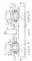
Die Erfindung wird nun anhand eines Ausführungsbeispiels mit Bezug auf die beigefügte Zeichnung näher erläutert. Hierbei zeigt die einzige Figur eine beispielhafte, vereinfachte Schnittdarstellung einer erfindungsgemäßen Scheibenbremse.The invention will now be explained in more detail using an exemplary embodiment with reference to the accompanying drawings. Here, the single figure shows an exemplary, simplified sectional view of a disc brake according to the invention.
In der Figur ist eine Scheibenbremse 1 gezeigt. Es kann zum Beispiel eine Schiebesattel-Scheibenbremse mit einem Bremszylinder (nicht dargestellt) sein, was eine von vielen möglichen Bauformen ist. Beiderseits einer nur angedeuteten Bremsscheibe 2, deren Drehrichtung 3 durch einen Pfeil angedeutet ist, sind Bremsbeläge angeordnet, von denen nur ein zuspannseitiger Bremsbelag 4 dargestellt ist. Der Bremsbelag 4 liegt an einer Bremsscheibenreibfläche an und ist mit seiner von der Bremsscheibe 2 abgewandten Seite über einen nicht gezeigten Belagträger mit einem Druckstück 5 verbunden, welches mittig mit einem Betätigungsstempel 6 einer nicht gezeigten Zuspanneinrichtung gekoppelt ist. Der Betätigungsstempel 6 ist zur Übertragung der in einer Zuspannrichtung 20 auf die Bremsscheibe 2 wirkenden Zuspannkräfte in nicht näher beschriebener Weise an dem Druckstück 5 angelenkt. Der zuspannseitige Bremsbelag 4 ist sowohl in Richtung parallel zu einer Drehachse der Bremsscheibe 2 als auch parallel zu einer Bremsscheibenreibfläche tangential zu der Drehrichtung 3 der Bremsscheibe beweglich.In the figure, a disc brake 1 is shown. It may for example be a sliding caliper disc brake with a brake cylinder (not shown), which is one of many possible designs. On both sides of only indicated
Mit Bezug auf die Drehrichtung 3 ist eine Einlaufseite ES des Bremsbelags 4 und eine Auslaufseite AS des Bremsbelags 4 festgelegt. Die Drehrichtung 3 entspricht einer Hauptdrehrichtung der Bremsscheibe 2, z.B. bei Vorwärtsfahrt eines zugehörigen Fahrzeugs.With reference to the rotational direction 3, an inlet side ES of the
In der in der Figur gezeigten Stellung ist der Bremsbelag 4 in Lösestellung. Das heißt, dass zwischen dem Bremsbelag 4 und der Bremsscheibe 2 ein so genanntes Lüftspiel L vorhanden ist.In the position shown in the figure, the
Links und rechts in der Figur von dem Betätigungsstempel 6 sind Verstärkungsstempel 7 und 8 in einer Parallelanordnung vorgesehen. Dabei ist ein erster Verstärkungsstempel 7 auf der Einlaufseite ES und ein zweiter Verstärkungsstempel 8 auf der Auslaufseite AS angeordnet. Die Stempel 6, 7 und 8 sind nur teilweise dargestellt, wobei ihre Verbindung mit der nicht gezeigten Zuspanneinrichtung ebenfalls nicht näher dargestellt ist.Left and right in the figure of the actuating plunger 6 reinforcing
Der erste Verstärkungsstempel 7 ist über ein einlaufseitiges Keillager 9, und der zweite Verstärkungsstempel 8 ist über in auslaufseitiges Keillager 9' mit dem Druckstück 5 gekoppelt.The first reinforcing
Das einlaufseitige Keillager 9 umfasst einen stempelseitigen Rampenträger 11, einen belagseitigen Rampenträger 12 und einen Rollkörper 10, welcher zwischen dem stempelseitigen Rampenträger 11 und dem belagseitigen Rampenträger 12 angeordnet ist. Der Rollkörper ist auf einer stempelseitigen Rampe 13 und einer belagseitigen Rampe 14 gehalten, wobei er auf diesen Rampen 13 und 14 bei einem Bremsvorgang abrollen kann, wie weiter unten beschrieben wird. Dazu weist die stempelseitige Rampe 13 einen einlaufseitigen Abschnitt mit einer stempelseitigen Ruherampe 15 auf, welcher zur Auslaufseite hin in einen Abschnitt übergeht, der hier als stempelseitige Freirampe 17 bezeichnet ist. Beide Rampenabschnitte 15 und 17 sind zur Bremsscheibe 2 hin geneigt. In gleicher Weise ist die gegenüberliegende belagseitige Rampe 14 mit zwei Rampenabschnitten aufgebaut, von denen eine belagseitige Ruherampe 16 zur Einlaufseite ES weist und eine belagseitige Freirampe 18 auslaufseitig angeordnet ist.The inlet-side wedge bearing 9 comprises a punch-side ramp support 11, a lining-
Das auslaufseitige Keillager 9' ist in gleicher Weise mit einem stempelseitigen Rampenträger 11', einem belagseitigen Rampenträger 12' und einem Rollkörper 10' aufgebaut, der ebenfalls auf einer stempelseitigen Rampe 13' und einer belagseitigen Rampe 14' gehalten ist. Die stempelseitige Rampe 13' weist eine einlaufseitig angeordnete stempelseitige Freirampe 17' und eine auslaufseitige stempelseitige Ruherampe 15' auf. Gegenüberliegend umfasst die belagseitige Rampe 14' eine einlaufseitig angeordnete belagseitige Freirampe 18' und eine auslaufseitig liegende belagseitige Ruherampe 16' auf. Im Gegensatz zum einlaufseitigen Keillager 9 ist das auslaufseitige Keillager 9' zu diesem spiegelbildlich aufgebaut.The outlet-side wedge bearing 9 'is constructed in the same way with a punch-side ramp support 11', a lining-side ramp support 12 'and a roller body 10', which is also held on a punch-side ramp 13 'and a lining-side ramp 14'. The punch-side ramp 13 'has an inlet side arranged stamp-side freewheel 17' and an outlet side punch-side rest lamp 15 '. Opposite, the lining-side ramp 14 'comprises an inlet-side free-ramp 18' arranged on the inlet side and a lining-side rest lamp 16 'on the outlet side. In contrast to the inlet side wedge bearing 9, the outlet side wedge bearing 9 'is constructed to this mirror image.
Die Rollkörper 10, 10' sind hier als Kugeln ausgebildet.The
In der in der Figur gezeigten Lösestellung, d.h. bei nicht betätigter Scheibenbremse 1, liegt der Rollkörper 10 des einlaufseitigen Keillagers 9 auf der stempelseitigen Rampe 13 an der stempelseitigen Ruherampe 15 und darunter auf der belagseitigen Rampe 14 an der belagseitigen Ruherampe 16 an. Im Gegensatz dazu liegt der Rollkörper 10' des auslaufseitigen Keillagers 9' auf der stempelseitige Rampe 13' an der stempelseitigen Ruherampe 15' zur Auslaufseite AS hin und darunter auf der belagseitigen Rampe 14' an der belagseitigen Ruherampe 16' zur Auslaufseite AS hin an, wobei die stempelseitige Ruherampe 15' und die darunter angeordnete belagseitige Ruherampe 16' des auslaufseitigen Keillagers 9' spiegelbildlich zum einlaufseitigen Keillager 9 zur Auslaufseite AS hin weisend angeordnet sind.In the release position shown in the figure, i. when the disc brake 1 is not actuated, the
Die Rampen 13, 14 des einlaufseitigen Keillagers 9 weisen zu Rampenwinkeln 19' der Rampen 13', 14' des auslaufseitigen Keillagers 9' unterschiedliche Rampenwinkel 19 auf. In diesem Ausführungsbeispiel besitzt das auslaufseitige Keillager 9' einen größeren Rampenwinkel 19' als das einlaufseitige Keillager 9. Die unterschiedlichen Rampenwinkel 19, 19' werden erst bei einem Bremsvorgang wirksam. Im nicht betätigten Zustand der Scheibenbremse 1 weisen die belagseitigen Rampen 14 und 14' der beiden Keillager 9 und 9' den gleichen Abstand zur Reibfläche der Bremsscheibe 2 auf.The
Eine Selbstverstärkungseinrichtung ist gebildet durch die folgenden Bauteile: Druckstück 5, Rollkörpern 10 und 10', Rampen 13, 14 und 13', 14' mit jeweiligen zugehörigen Verstärkungsstempeln 7 und 8, sowie weiteren Funktionseinheiten bzw. - abschnitten, die hier nicht dargestellt sind. Eine ausführliche Beschreibung der Selbstverstärkungseinrichtung und ihrer Funktion wird zum Beispiel in der Offenlegungsschrift
Bei einer Bremsbetätigung wird der Bremsbelag 4 durch über das Druckstück 5 durch den auf diese einwirkenden Betätigungsstempel 6 in Zuspannrichtung 20 gegen die Reibfläche der Bremsscheibe 2 gedrückt, wobei zunächst das Lüftspiel L durchlaufen wird. Dann erfolgt bei Kontakt des Bremsbelags 4 mit der Bremsscheibe 2 eine Umfangsverschiebung des Bremsbelags 4 tangential zur Drehrichtung 3 der Bremsscheibe. Dabei bewegt sich der Bremsbelag 4 mit dem Druckstück 5 und den belagseitigen Rampenträgern 12, 12' der Keillager 9, 9' relativ zu den feststehenden stempelseitigen Rampenträgern 11, 11'. Diese Relativbewegung wird durch Abrollen bzw. Abwälzen der Rollkörper 10, 10' auf den Rampen 13, 14 und 13', 14' ermöglicht. Der Bremsbelag 4 wird nun durch den größeren Rampenwinkel 19' am auslaufseitigen Keillager 9' mit dem zweiten Verstärkungsstempel 8 stärker auf die Bremsscheibe 2 in Zuspannrichtung 20 zu bewegt ("voreilt") als dies auf der Einlaufseite ES der Fall ist. Auf diese Weise wird ein ungleichmäßiger Verschleiß des Bremsbelags 4 vermieden, da üblicherweise ohne diese Maßnahme ein stärkerer Verschleiß an der Einlaufseite ES auftritt. Dieses wird durch das oben beschriebene "Voreilen" des Bremsbelags 4 auf der Auslaufseite AS kompensiert.In a brake operation, the
Der sich daraus zwischen Auslaufseite AS und Einlaufseite ES ergebende Positionsunterschied ist bei konstanten Rampenwinkeln 19, 19' zur Umfangsverschiebung des Bremsbelags 4 angenähert proportional. Bei Vorliegen eines größeren Lüftspiels L und damit eines entsprechenden größeren Leerwegs im Anlagevorgang des Bremsbelags 4 an die Bremsscheibe 2 wird bei Berührung von Bremsbelag 4 und Bremsscheibe 2 diese anfängliche Umfangsverschiebung vor Eintreten des Spannkraftaufbaus sprunghaft ausgeführt. Es liegt nach Überwinden des Lüftspiels L schon eine ungleiche Justage des Bremsbelags 4 vor, welche dann bei weiterem Kraftaufbau entsprechend der weiteren Umfangsverschiebung des Bremsbelags 4 weiter vergrö-βert wird. In diesem Fall existiert eine Kombination eines konstanten Justageanteils, welcher mit einem von der Spannkraft abhängigen Anteil kombiniert wird. Eine derartige Auslegung ist für die meisten Anwendungen vorteilhaft.The position difference resulting therefrom between the outlet side AS and the inlet side ES is approximately proportional to the peripheral displacement of the
Um den konstanten Justageanteil zu vermeiden, ist es erforderlich, die Rampensteigung, d.h. den Rampenwinkel 19, 19' im Lüftspielbereich auf den einlaufseitigen und auslaufseitigen Rampen zunächst konstant zu halten und erst bei Erreichen des beginnenden Spannkraftaufbaus eine unterschiedliche Steigung, d.h. einen unterschiedlichen Rampenwinkel 19, 19' anzuwenden. Der gesamte Steigungs- bzw. Winkelunterschied muss dann zur Erzielung eines gleichwertigen Effekts im Bereich der sehr häufigen Anpassungsbremsungen stärker ausfallen als im Falle einer Auslegung mit gleichbleibend unterschiedlichem Rampenwinkel 19, 19'.In order to avoid the constant adjustment portion, it is necessary to first keep the ramp pitch, ie the
In der folgenden Tabelle ist ein Beispiel für eine konstante Rampensteigung (Rampenwinkel 19, 19') bei einem Lüftspiel L (Leerweg) von 1 mm aufgezeigt.
Der Krafthub setzt sich zusammen aus dem Hub minus 1 mm Leerweg.The power stroke is composed of the stroke minus 1 mm free travel.
Der Umfangsweg ist der Weg, um den der Bremsbelag 4 tangential in Drehrichtung 3 der Bremsscheibe 2 beim Bremsvorgang verschoben wird.The circumferential path is the path by which the
In einer weiteren Tabelle weist die einlaufseitige Rampe 13, 14 eine gestufte Rampensteigung bzw. einen gestuften Rampenwinkel 19 auf. Die Abstufung des Rampenwinkels 19 beträgt beim Leerweg 34° und beim Krafthub 30°.
Um mit der gestuften Rampensteigung (dem gestuften Rampenwinkel 19) im Hauptbetriebsbereich der Scheibenbremse 1 vergleichbare Wirkung wie bei der Rampe mit konstanter Steigung zu erzielen, ist eine Verdoppelung des Unterschieds in den Rampenwinkeln von 2° auf 4° erforderlich. Durch eine solche Spreizung des Bereichs der Rampenwinkel 19, 19' wird der Grad der nutzbaren Selbstverstärkung geschmälert. Allerdings ist die einen Schrägverschleiß kompensierende Wirkung im gesamten Arbeitsbereich der Scheibenbremse nahezu gleich.In order to achieve the effect of the stepped ramp slope (the stepped ramp angle 19) in the main operating range of the disc brake 1 comparable effect as the ramp with constant pitch, a doubling of the difference in the ramp angles from 2 ° to 4 ° is required. By such a spreading of the range of the ramp angles 19, 19 ', the degree of useful self-amplification is reduced. However, the oblique wear compensating effect is almost the same throughout the working range of the disc brake.
Der Unterschied der Rampenwinkel 19, 19' ist bevorzugt so gewählt, dass eine Hubdifferenz der belagseitigen Rampen 14, 14' einen prozentualen Anteil des ausgeführten Krafthubs der Scheibenbremse 1 im Bereich von 10...30 %, vorzugsweise 15 % ausmacht.The difference between the ramp angles 19, 19 'is preferably selected so that a stroke difference of the lining-
Die Erfindung ist nicht auf die oben beschriebenen Ausführungsbeispiele beschränkt, sondern im Rahmen der beigefügten Ansprüche modifizierbar.The invention is not limited to the embodiments described above, but can be modified within the scope of the appended claims.
Es ist zum Beispiel denkbar, dass eine Kombination aus ungleichen Rampenwinkeln 19, 19' und einer Vorjustage eines Verstärkungsstempels 7 oder 8 mit einer Voreilung bzw. einem Vorhub möglich ist. Damit können auch solche Effekte kompensiert werden, welche sich z. B. aus einer Schrägstellung des Bremssattels beispielsweise aufgrund von Lagerspielen ergeben. Diese Vorjustage kann z. B. gemäß
Die gestufte Rampensteigung kann mehr als zwei Rampenwinkel aufweisen. Auch können die Übergänge zwischen den Stufen ausgerundet werden. Es ist auch möglich, dass die Rampe einen Kurvenverlauf mit ineinander übergehenden Rampenwinkeln aufweist.The stepped ramp slope may have more than two ramp angles. Also, the transitions between the stages can be rounded. It is also possible that the ramp has a curve with merging ramp angles.
- 11
- Scheibenbremsedisc brake
- 22
- Bremsscheibebrake disc
- 33
- Drehrichtungdirection of rotation
- 44
- Bremsbelagbrake lining
- 55
- DruckstückPressure piece
- 66
- Betätigungsstempelactuating ram
- 77
- Erster VerstärkungsstempelFirst reinforcement stamp
- 88th
- Zweiter VerstärkungsstempelSecond reinforcement stamp
- 99
- Einlaufseitiges KeillagerInlet wedge bearing
- 9'9 '
- Auslaufseitiges KeillagerOutlet wedge bearing
- 10, 10'10, 10 '
- Rollkörperroll body
- 11, 11'11, 11 '
- Stempelseitiger RampenträgerStamp-side ramp carrier
- 12, 12'12, 12 '
- Belagseitiger RampenträgerPad-side ramp carrier
- 13, 13'13, 13 '
- Stempelseitige RampeStamp-side ramp
- 14, 14'14, 14 '
- Belagseitige RampeLining-side ramp
- 15, 15'15, 15 '
- Stempelseitige RuherampeStamp-side rest lamp
- 16, 16'16, 16 '
- Belagseitige RuherampeCoating side rest lamp
- 17, 17'17, 17 '
- Stempelseitige FreirampeStamp-side freewheel
- 18, 18'18, 18 '
- Belagseitige FreirampeSurface-side freewheel
- 19, 19'19, 19 '
- Rampenwinkelramp angle
- 2020
- Zuspannrichtungthe application direction
- ASAS
- Auslaufseiteoutlet side
- ESIT
- Einlaufseiteinlet side
- LL
- Lüftspielclearance
Claims (10)
- Disc brake (1), comprising:a. a brake calliper, at least one application-side and one reaction-side brake pad (4) and a brake disc (2);b. wherein the at least one application-side brake pad (4) is movable both in a direction parallel to a brake disc axis of rotation and in a direction parallel to a brake disc friction surface;c. further comprising an actuating device acting on an actuating plunger (6), the actuating plunger (6) being coupled to a pressure pad (5) of the application-side brake pad (4); andd. further comprising a self-energising device comprising the pressure pad and at least two energising plungers (7, 8) with a taper bearing (9, 9') each, each of the taper bearings (9, 9') having a rolling body (10, 10') located between ramps (13, 14 and 13', 14'),
characterised in thate. the two taper bearings (9, 9') differ in their shape in such a way that the ramps (13, 14 and 13', 14') of the two taper bearings (9, 9') have different ramp angles (19, 19') if viewed in the same direction tangential to a direction of rotation (3) of the brake disc (2). - Disc brake (1) according to claim 1, characterised in that the ramps (13', 14') of the taper bearing (9') located on an outgoing side (AS) related to a direction of rotation (3) of the brake disc (2) have a larger ramp angle (19') than the ramps (13, 14) of the taper bearing (9) located on an ingoing side (ES) related to a direction of rotation (3) of the brake disc (2).
- Disc brake (1) according to claim 1 or 2, characterised in that the pad-side ramps (14, 14') of the two taper bearings (9, 9') are located at a same distance from the friction surface of the brake disc (2) in the non-actuated state of the disc brake (1).
- Disc brake (1) according to any of the preceding claims, characterised in that the ramp angles (19, 19') differ by a value in the range of 2....4 degrees.
- Disc brake (1) according to claim 4, characterised in that the ramp angles (19, 19') differ by a value of approximately 2 degrees.
- Disc brake (1) according to any of the preceding claims, characterised in that at least one of the ramp angles (19, 19') has at least two stages.
- Disc brake (1) according to claim 6, characterised in that the at least two stages differ by an angle in the range of 2....4 degrees.
- Disc brake (1) according to claim 6 or 7, characterised in that the angle of the first stage of the at least one of the ramp angles (19, 19') having at least two stages has the same value as that of the other of the ramp angles (19, 19').
- Disc brake (1) according to any of the preceding claims, characterised in that a difference of the ramp angles (19, 19') is chosen such that a stroke differential of the pad-side ramps (19, 19') amounts to a percentage of a power stroke of the disc brake (1) in the range of 10....30%, preferably 15%.
- Disc brake (1) according to any of the preceding claims, characterised in that the disc brake (1) comprises at least one adjusting device with an adjusting gear, wherein each plunger (6, 7, 8) is provided with a threaded spindle and wherein the energising plunger (8) located on an outgoing side (AS) related to a direction of rotation (3) of the brake disc (2) is provided with a pre-stroke.
Applications Claiming Priority (1)
| Application Number | Priority Date | Filing Date | Title |
|---|---|---|---|
| DE102010050099A DE102010050099A1 (en) | 2010-10-29 | 2010-10-29 | Disc brake with a self-energizing device |
Publications (3)
| Publication Number | Publication Date |
|---|---|
| EP2447563A2 EP2447563A2 (en) | 2012-05-02 |
| EP2447563A3 EP2447563A3 (en) | 2014-07-30 |
| EP2447563B1 true EP2447563B1 (en) | 2015-08-19 |
Family
ID=45062875
Family Applications (1)
| Application Number | Title | Priority Date | Filing Date |
|---|---|---|---|
| EP11186681.0A Active EP2447563B1 (en) | 2010-10-29 | 2011-10-26 | Disc brake with a self-reinforcement device |
Country Status (2)
| Country | Link |
|---|---|
| EP (1) | EP2447563B1 (en) |
| DE (1) | DE102010050099A1 (en) |
Families Citing this family (2)
| Publication number | Priority date | Publication date | Assignee | Title |
|---|---|---|---|---|
| PL2963369T3 (en) | 2014-07-05 | 2018-10-31 | Linde Aktiengesellschaft | Method and device for the cryogenic decomposition of air |
| EP2963370B1 (en) | 2014-07-05 | 2018-06-13 | Linde Aktiengesellschaft | Method and device for the cryogenic decomposition of air |
Family Cites Families (6)
| Publication number | Priority date | Publication date | Assignee | Title |
|---|---|---|---|---|
| DE4212353A1 (en) | 1992-04-13 | 1993-10-14 | Knorr Bremse Ag | Air operated disc brake |
| DE102005030621A1 (en) * | 2004-10-13 | 2006-04-20 | Knorr-Bremse Systeme für Nutzfahrzeuge GmbH | Disc brake in self-reinforcing design and control method for a self-energizing brake |
| DE102006029942A1 (en) * | 2006-01-12 | 2007-08-02 | Knorr-Bremse Systeme für Nutzfahrzeuge GmbH | Self-energizing disc brake with electromechanical actuator |
| DE102006003749A1 (en) * | 2006-01-26 | 2007-08-09 | Knorr-Bremse Systeme für Nutzfahrzeuge GmbH | Disc brake in self-reinforcing design |
| DE102006036279B3 (en) * | 2006-08-03 | 2008-04-10 | Knorr-Bremse Systeme für Nutzfahrzeuge GmbH | Electromechanically operated disc brake with actuating tappet |
| DE102008004806A1 (en) | 2008-01-17 | 2009-07-30 | Knorr-Bremse Systeme für Nutzfahrzeuge GmbH | Pneumatically actuated disc brake with actuating tappet |
-
2010
- 2010-10-29 DE DE102010050099A patent/DE102010050099A1/en not_active Ceased
-
2011
- 2011-10-26 EP EP11186681.0A patent/EP2447563B1/en active Active
Also Published As
| Publication number | Publication date |
|---|---|
| EP2447563A2 (en) | 2012-05-02 |
| EP2447563A3 (en) | 2014-07-30 |
| DE102010050099A1 (en) | 2012-05-03 |
Similar Documents
| Publication | Publication Date | Title |
|---|---|---|
| EP2222977B1 (en) | Electromechanical friction brake | |
| EP2196694B1 (en) | Electromechancally actuated disc brake with guide plate | |
| EP1692413B1 (en) | Self-energising electromechanical vehicle brake | |
| EP2644926A1 (en) | Disc brake comprising a reset mechanism, and corresponding brake lining | |
| EP0659242B1 (en) | Compressed-air actuated disc brake | |
| EP3253985B1 (en) | Disk brake for a utility-vehicle wheel | |
| WO2004099645A1 (en) | Hydraulically actuated vehicle brake | |
| DE102015114547B4 (en) | Disc brake for a commercial vehicle | |
| EP1994301B1 (en) | Disk brake | |
| EP1700053A1 (en) | Self-boosting electromechanical friction brake | |
| EP2106509B1 (en) | Disk brake for a motor vehicle and housing for the same | |
| EP2447563B1 (en) | Disc brake with a self-reinforcement device | |
| EP2005023B1 (en) | Self-energizing electromechanical partially lined disc brake | |
| EP0760061B1 (en) | Device for applying a disc brake | |
| DE102012110458A1 (en) | Disk brake for commercial vehicle, has swingable brake lever attached with bridge, and adjustable piston rams arranged in bridge in parallel manner and stretched along lateral axis of liner support plate | |
| EP0654615A1 (en) | Support of a brake pad of a disc brake | |
| DE102008006481B4 (en) | Disc brake for a commercial vehicle | |
| EP1920167B1 (en) | Self-energizing friction brake | |
| DE102007016486A1 (en) | Electromechanically operated disc brake with actuating tappet | |
| EP1700052A1 (en) | Self-energizing electromechanical friction brake | |
| DE102013101636A1 (en) | Disk brake for use in vehicle, particularly heavy-duty commercial vehicles, has pressure plate that is designed as perforated disk, locking ring to lock pressure plate axially and pin that is locked axially with respect to brake pad | |
| DE102007008727B4 (en) | Disc brake, in particular for a commercial vehicle | |
| DE102005055441A1 (en) | Electromechanical vehicle brake with friction lining wear compensation device | |
| DE202022103255U1 (en) | Positioning arrangement and brake piston arrangement | |
| EP2754913A2 (en) | Disc brake for vehicles |
Legal Events
| Date | Code | Title | Description |
|---|---|---|---|
| PUAI | Public reference made under article 153(3) epc to a published international application that has entered the european phase |
Free format text: ORIGINAL CODE: 0009012 |
|
| AK | Designated contracting states |
Kind code of ref document: A2 Designated state(s): AL AT BE BG CH CY CZ DE DK EE ES FI FR GB GR HR HU IE IS IT LI LT LU LV MC MK MT NL NO PL PT RO RS SE SI SK SM TR |
|
| AX | Request for extension of the european patent |
Extension state: BA ME |
|
| PUAL | Search report despatched |
Free format text: ORIGINAL CODE: 0009013 |
|
| AK | Designated contracting states |
Kind code of ref document: A3 Designated state(s): AL AT BE BG CH CY CZ DE DK EE ES FI FR GB GR HR HU IE IS IT LI LT LU LV MC MK MT NL NO PL PT RO RS SE SI SK SM TR |
|
| AX | Request for extension of the european patent |
Extension state: BA ME |
|
| RIC1 | Information provided on ipc code assigned before grant |
Ipc: F16D 65/14 20060101AFI20140625BHEP Ipc: F16D 127/10 20120101ALI20140625BHEP |
|
| 17P | Request for examination filed |
Effective date: 20150130 |
|
| RBV | Designated contracting states (corrected) |
Designated state(s): AL AT BE BG CH CY CZ DE DK EE ES FI FR GB GR HR HU IE IS IT LI LT LU LV MC MK MT NL NO PL PT RO RS SE SI SK SM TR |
|
| GRAP | Despatch of communication of intention to grant a patent |
Free format text: ORIGINAL CODE: EPIDOSNIGR1 |
|
| INTG | Intention to grant announced |
Effective date: 20150316 |
|
| GRAS | Grant fee paid |
Free format text: ORIGINAL CODE: EPIDOSNIGR3 |
|
| GRAA | (expected) grant |
Free format text: ORIGINAL CODE: 0009210 |
|
| AK | Designated contracting states |
Kind code of ref document: B1 Designated state(s): AL AT BE BG CH CY CZ DE DK EE ES FI FR GB GR HR HU IE IS IT LI LT LU LV MC MK MT NL NO PL PT RO RS SE SI SK SM TR |
|
| REG | Reference to a national code |
Ref country code: GB Ref legal event code: FG4D Free format text: NOT ENGLISH |
|
| REG | Reference to a national code |
Ref country code: CH Ref legal event code: EP |
|
| REG | Reference to a national code |
Ref country code: IE Ref legal event code: FG4D Free format text: LANGUAGE OF EP DOCUMENT: GERMAN |
|
| REG | Reference to a national code |
Ref country code: AT Ref legal event code: REF Ref document number: 744050 Country of ref document: AT Kind code of ref document: T Effective date: 20150915 |
|
| REG | Reference to a national code |
Ref country code: DE Ref legal event code: R096 Ref document number: 502011007626 Country of ref document: DE |
|
| REG | Reference to a national code |
Ref country code: NL Ref legal event code: FP |
|
| REG | Reference to a national code |
Ref country code: SE Ref legal event code: TRGR |
|
| REG | Reference to a national code |
Ref country code: LT Ref legal event code: MG4D |
|
| PG25 | Lapsed in a contracting state [announced via postgrant information from national office to epo] |
Ref country code: NO Free format text: LAPSE BECAUSE OF FAILURE TO SUBMIT A TRANSLATION OF THE DESCRIPTION OR TO PAY THE FEE WITHIN THE PRESCRIBED TIME-LIMIT Effective date: 20151119 Ref country code: LV Free format text: LAPSE BECAUSE OF FAILURE TO SUBMIT A TRANSLATION OF THE DESCRIPTION OR TO PAY THE FEE WITHIN THE PRESCRIBED TIME-LIMIT Effective date: 20150819 Ref country code: GR Free format text: LAPSE BECAUSE OF FAILURE TO SUBMIT A TRANSLATION OF THE DESCRIPTION OR TO PAY THE FEE WITHIN THE PRESCRIBED TIME-LIMIT Effective date: 20151120 Ref country code: FI Free format text: LAPSE BECAUSE OF FAILURE TO SUBMIT A TRANSLATION OF THE DESCRIPTION OR TO PAY THE FEE WITHIN THE PRESCRIBED TIME-LIMIT Effective date: 20150819 Ref country code: LT Free format text: LAPSE BECAUSE OF FAILURE TO SUBMIT A TRANSLATION OF THE DESCRIPTION OR TO PAY THE FEE WITHIN THE PRESCRIBED TIME-LIMIT Effective date: 20150819 |
|
| PG25 | Lapsed in a contracting state [announced via postgrant information from national office to epo] |
Ref country code: RS Free format text: LAPSE BECAUSE OF FAILURE TO SUBMIT A TRANSLATION OF THE DESCRIPTION OR TO PAY THE FEE WITHIN THE PRESCRIBED TIME-LIMIT Effective date: 20150819 Ref country code: ES Free format text: LAPSE BECAUSE OF FAILURE TO SUBMIT A TRANSLATION OF THE DESCRIPTION OR TO PAY THE FEE WITHIN THE PRESCRIBED TIME-LIMIT Effective date: 20150819 Ref country code: PL Free format text: LAPSE BECAUSE OF FAILURE TO SUBMIT A TRANSLATION OF THE DESCRIPTION OR TO PAY THE FEE WITHIN THE PRESCRIBED TIME-LIMIT Effective date: 20150819 Ref country code: PT Free format text: LAPSE BECAUSE OF FAILURE TO SUBMIT A TRANSLATION OF THE DESCRIPTION OR TO PAY THE FEE WITHIN THE PRESCRIBED TIME-LIMIT Effective date: 20151221 Ref country code: IS Free format text: LAPSE BECAUSE OF FAILURE TO SUBMIT A TRANSLATION OF THE DESCRIPTION OR TO PAY THE FEE WITHIN THE PRESCRIBED TIME-LIMIT Effective date: 20151219 |
|
| PGFP | Annual fee paid to national office [announced via postgrant information from national office to epo] |
Ref country code: NL Payment date: 20151026 Year of fee payment: 5 |
|
| PG25 | Lapsed in a contracting state [announced via postgrant information from national office to epo] |
Ref country code: SK Free format text: LAPSE BECAUSE OF FAILURE TO SUBMIT A TRANSLATION OF THE DESCRIPTION OR TO PAY THE FEE WITHIN THE PRESCRIBED TIME-LIMIT Effective date: 20150819 Ref country code: CZ Free format text: LAPSE BECAUSE OF FAILURE TO SUBMIT A TRANSLATION OF THE DESCRIPTION OR TO PAY THE FEE WITHIN THE PRESCRIBED TIME-LIMIT Effective date: 20150819 Ref country code: EE Free format text: LAPSE BECAUSE OF FAILURE TO SUBMIT A TRANSLATION OF THE DESCRIPTION OR TO PAY THE FEE WITHIN THE PRESCRIBED TIME-LIMIT Effective date: 20150819 Ref country code: DK Free format text: LAPSE BECAUSE OF FAILURE TO SUBMIT A TRANSLATION OF THE DESCRIPTION OR TO PAY THE FEE WITHIN THE PRESCRIBED TIME-LIMIT Effective date: 20150819 |
|
| PGFP | Annual fee paid to national office [announced via postgrant information from national office to epo] |
Ref country code: IT Payment date: 20151127 Year of fee payment: 5 |
|
| REG | Reference to a national code |
Ref country code: DE Ref legal event code: R097 Ref document number: 502011007626 Country of ref document: DE |
|
| PG25 | Lapsed in a contracting state [announced via postgrant information from national office to epo] |
Ref country code: LU Free format text: LAPSE BECAUSE OF FAILURE TO SUBMIT A TRANSLATION OF THE DESCRIPTION OR TO PAY THE FEE WITHIN THE PRESCRIBED TIME-LIMIT Effective date: 20151026 Ref country code: RO Free format text: LAPSE BECAUSE OF FAILURE TO SUBMIT A TRANSLATION OF THE DESCRIPTION OR TO PAY THE FEE WITHIN THE PRESCRIBED TIME-LIMIT Effective date: 20150819 |
|
| REG | Reference to a national code |
Ref country code: CH Ref legal event code: PL |
|
| PLBE | No opposition filed within time limit |
Free format text: ORIGINAL CODE: 0009261 |
|
| STAA | Information on the status of an ep patent application or granted ep patent |
Free format text: STATUS: NO OPPOSITION FILED WITHIN TIME LIMIT |
|
| PG25 | Lapsed in a contracting state [announced via postgrant information from national office to epo] |
Ref country code: MC Free format text: LAPSE BECAUSE OF FAILURE TO SUBMIT A TRANSLATION OF THE DESCRIPTION OR TO PAY THE FEE WITHIN THE PRESCRIBED TIME-LIMIT Effective date: 20150819 |
|
| 26N | No opposition filed |
Effective date: 20160520 |
|
| REG | Reference to a national code |
Ref country code: IE Ref legal event code: MM4A |
|
| PG25 | Lapsed in a contracting state [announced via postgrant information from national office to epo] |
Ref country code: CH Free format text: LAPSE BECAUSE OF NON-PAYMENT OF DUE FEES Effective date: 20151031 Ref country code: LI Free format text: LAPSE BECAUSE OF NON-PAYMENT OF DUE FEES Effective date: 20151031 |
|
| REG | Reference to a national code |
Ref country code: FR Ref legal event code: ST Effective date: 20160630 |
|
| PG25 | Lapsed in a contracting state [announced via postgrant information from national office to epo] |
Ref country code: FR Free format text: LAPSE BECAUSE OF NON-PAYMENT OF DUE FEES Effective date: 20151102 Ref country code: SI Free format text: LAPSE BECAUSE OF FAILURE TO SUBMIT A TRANSLATION OF THE DESCRIPTION OR TO PAY THE FEE WITHIN THE PRESCRIBED TIME-LIMIT Effective date: 20150819 |
|
| PG25 | Lapsed in a contracting state [announced via postgrant information from national office to epo] |
Ref country code: IE Free format text: LAPSE BECAUSE OF NON-PAYMENT OF DUE FEES Effective date: 20151026 |
|
| PG25 | Lapsed in a contracting state [announced via postgrant information from national office to epo] |
Ref country code: SM Free format text: LAPSE BECAUSE OF FAILURE TO SUBMIT A TRANSLATION OF THE DESCRIPTION OR TO PAY THE FEE WITHIN THE PRESCRIBED TIME-LIMIT Effective date: 20150819 Ref country code: BG Free format text: LAPSE BECAUSE OF FAILURE TO SUBMIT A TRANSLATION OF THE DESCRIPTION OR TO PAY THE FEE WITHIN THE PRESCRIBED TIME-LIMIT Effective date: 20150819 Ref country code: HU Free format text: LAPSE BECAUSE OF FAILURE TO SUBMIT A TRANSLATION OF THE DESCRIPTION OR TO PAY THE FEE WITHIN THE PRESCRIBED TIME-LIMIT; INVALID AB INITIO Effective date: 20111026 |
|
| REG | Reference to a national code |
Ref country code: NL Ref legal event code: MM Effective date: 20161101 |
|
| PG25 | Lapsed in a contracting state [announced via postgrant information from national office to epo] |
Ref country code: CY Free format text: LAPSE BECAUSE OF FAILURE TO SUBMIT A TRANSLATION OF THE DESCRIPTION OR TO PAY THE FEE WITHIN THE PRESCRIBED TIME-LIMIT Effective date: 20150819 |
|
| PG25 | Lapsed in a contracting state [announced via postgrant information from national office to epo] |
Ref country code: BE Free format text: LAPSE BECAUSE OF NON-PAYMENT OF DUE FEES Effective date: 20151031 Ref country code: HR Free format text: LAPSE BECAUSE OF FAILURE TO SUBMIT A TRANSLATION OF THE DESCRIPTION OR TO PAY THE FEE WITHIN THE PRESCRIBED TIME-LIMIT Effective date: 20150819 |
|
| PG25 | Lapsed in a contracting state [announced via postgrant information from national office to epo] |
Ref country code: NL Free format text: LAPSE BECAUSE OF NON-PAYMENT OF DUE FEES Effective date: 20161101 Ref country code: MT Free format text: LAPSE BECAUSE OF FAILURE TO SUBMIT A TRANSLATION OF THE DESCRIPTION OR TO PAY THE FEE WITHIN THE PRESCRIBED TIME-LIMIT Effective date: 20150819 Ref country code: TR Free format text: LAPSE BECAUSE OF FAILURE TO SUBMIT A TRANSLATION OF THE DESCRIPTION OR TO PAY THE FEE WITHIN THE PRESCRIBED TIME-LIMIT Effective date: 20150819 |
|
| PG25 | Lapsed in a contracting state [announced via postgrant information from national office to epo] |
Ref country code: IT Free format text: LAPSE BECAUSE OF NON-PAYMENT OF DUE FEES Effective date: 20161026 |
|
| REG | Reference to a national code |
Ref country code: AT Ref legal event code: MM01 Ref document number: 744050 Country of ref document: AT Kind code of ref document: T Effective date: 20161026 |
|
| PG25 | Lapsed in a contracting state [announced via postgrant information from national office to epo] |
Ref country code: AT Free format text: LAPSE BECAUSE OF NON-PAYMENT OF DUE FEES Effective date: 20161026 |
|
| PG25 | Lapsed in a contracting state [announced via postgrant information from national office to epo] |
Ref country code: MK Free format text: LAPSE BECAUSE OF FAILURE TO SUBMIT A TRANSLATION OF THE DESCRIPTION OR TO PAY THE FEE WITHIN THE PRESCRIBED TIME-LIMIT Effective date: 20150819 |
|
| PG25 | Lapsed in a contracting state [announced via postgrant information from national office to epo] |
Ref country code: AL Free format text: LAPSE BECAUSE OF FAILURE TO SUBMIT A TRANSLATION OF THE DESCRIPTION OR TO PAY THE FEE WITHIN THE PRESCRIBED TIME-LIMIT Effective date: 20150819 |
|
| PGFP | Annual fee paid to national office [announced via postgrant information from national office to epo] |
Ref country code: DE Payment date: 20191023 Year of fee payment: 9 Ref country code: SE Payment date: 20191023 Year of fee payment: 9 |
|
| REG | Reference to a national code |
Ref country code: DE Ref legal event code: R119 Ref document number: 502011007626 Country of ref document: DE |
|
| REG | Reference to a national code |
Ref country code: SE Ref legal event code: EUG |
|
| PG25 | Lapsed in a contracting state [announced via postgrant information from national office to epo] |
Ref country code: DE Free format text: LAPSE BECAUSE OF NON-PAYMENT OF DUE FEES Effective date: 20210501 |
|
| PG25 | Lapsed in a contracting state [announced via postgrant information from national office to epo] |
Ref country code: SE Free format text: LAPSE BECAUSE OF NON-PAYMENT OF DUE FEES Effective date: 20201027 |
|
| P01 | Opt-out of the competence of the unified patent court (upc) registered |
Effective date: 20230607 |
|
| PGFP | Annual fee paid to national office [announced via postgrant information from national office to epo] |
Ref country code: GB Payment date: 20231025 Year of fee payment: 13 |