EP2644926A1 - Disc brake comprising a reset mechanism, and corresponding brake lining - Google Patents
Disc brake comprising a reset mechanism, and corresponding brake lining Download PDFInfo
- Publication number
- EP2644926A1 EP2644926A1 EP13160539.6A EP13160539A EP2644926A1 EP 2644926 A1 EP2644926 A1 EP 2644926A1 EP 13160539 A EP13160539 A EP 13160539A EP 2644926 A1 EP2644926 A1 EP 2644926A1
- Authority
- EP
- European Patent Office
- Prior art keywords
- brake
- disc
- return
- lining
- carrier
- Prior art date
- Legal status (The legal status is an assumption and is not a legal conclusion. Google has not performed a legal analysis and makes no representation as to the accuracy of the status listed.)
- Granted
Links
Images


Classifications
-
- F—MECHANICAL ENGINEERING; LIGHTING; HEATING; WEAPONS; BLASTING
- F16—ENGINEERING ELEMENTS AND UNITS; GENERAL MEASURES FOR PRODUCING AND MAINTAINING EFFECTIVE FUNCTIONING OF MACHINES OR INSTALLATIONS; THERMAL INSULATION IN GENERAL
- F16D—COUPLINGS FOR TRANSMITTING ROTATION; CLUTCHES; BRAKES
- F16D65/00—Parts or details
- F16D65/02—Braking members; Mounting thereof
- F16D65/04—Bands, shoes or pads; Pivots or supporting members therefor
- F16D65/092—Bands, shoes or pads; Pivots or supporting members therefor for axially-engaging brakes, e.g. disc brakes
- F16D65/095—Pivots or supporting members therefor
- F16D65/097—Resilient means interposed between pads and supporting members or other brake parts
- F16D65/0973—Resilient means interposed between pads and supporting members or other brake parts not subjected to brake forces
- F16D65/0974—Resilient means interposed between pads and supporting members or other brake parts not subjected to brake forces acting on or in the vicinity of the pad rim in a direction substantially transverse to the brake disc axis
-
- F—MECHANICAL ENGINEERING; LIGHTING; HEATING; WEAPONS; BLASTING
- F16—ENGINEERING ELEMENTS AND UNITS; GENERAL MEASURES FOR PRODUCING AND MAINTAINING EFFECTIVE FUNCTIONING OF MACHINES OR INSTALLATIONS; THERMAL INSULATION IN GENERAL
- F16D—COUPLINGS FOR TRANSMITTING ROTATION; CLUTCHES; BRAKES
- F16D55/00—Brakes with substantially-radial braking surfaces pressed together in axial direction, e.g. disc brakes
- F16D55/02—Brakes with substantially-radial braking surfaces pressed together in axial direction, e.g. disc brakes with axially-movable discs or pads pressed against axially-located rotating members
- F16D55/22—Brakes with substantially-radial braking surfaces pressed together in axial direction, e.g. disc brakes with axially-movable discs or pads pressed against axially-located rotating members by clamping an axially-located rotating disc between movable braking members, e.g. movable brake discs or brake pads
- F16D55/224—Brakes with substantially-radial braking surfaces pressed together in axial direction, e.g. disc brakes with axially-movable discs or pads pressed against axially-located rotating members by clamping an axially-located rotating disc between movable braking members, e.g. movable brake discs or brake pads with a common actuating member for the braking members
- F16D55/225—Brakes with substantially-radial braking surfaces pressed together in axial direction, e.g. disc brakes with axially-movable discs or pads pressed against axially-located rotating members by clamping an axially-located rotating disc between movable braking members, e.g. movable brake discs or brake pads with a common actuating member for the braking members the braking members being brake pads
-
- F—MECHANICAL ENGINEERING; LIGHTING; HEATING; WEAPONS; BLASTING
- F16—ENGINEERING ELEMENTS AND UNITS; GENERAL MEASURES FOR PRODUCING AND MAINTAINING EFFECTIVE FUNCTIONING OF MACHINES OR INSTALLATIONS; THERMAL INSULATION IN GENERAL
- F16D—COUPLINGS FOR TRANSMITTING ROTATION; CLUTCHES; BRAKES
- F16D65/00—Parts or details
- F16D65/02—Braking members; Mounting thereof
- F16D65/04—Bands, shoes or pads; Pivots or supporting members therefor
- F16D65/092—Bands, shoes or pads; Pivots or supporting members therefor for axially-engaging brakes, e.g. disc brakes
- F16D65/095—Pivots or supporting members therefor
- F16D65/097—Resilient means interposed between pads and supporting members or other brake parts
- F16D65/0973—Resilient means interposed between pads and supporting members or other brake parts not subjected to brake forces
-
- F—MECHANICAL ENGINEERING; LIGHTING; HEATING; WEAPONS; BLASTING
- F16—ENGINEERING ELEMENTS AND UNITS; GENERAL MEASURES FOR PRODUCING AND MAINTAINING EFFECTIVE FUNCTIONING OF MACHINES OR INSTALLATIONS; THERMAL INSULATION IN GENERAL
- F16D—COUPLINGS FOR TRANSMITTING ROTATION; CLUTCHES; BRAKES
- F16D65/00—Parts or details
- F16D65/14—Actuating mechanisms for brakes; Means for initiating operation at a predetermined position
- F16D65/16—Actuating mechanisms for brakes; Means for initiating operation at a predetermined position arranged in or on the brake
- F16D65/18—Actuating mechanisms for brakes; Means for initiating operation at a predetermined position arranged in or on the brake adapted for drawing members together, e.g. for disc brakes
-
- F—MECHANICAL ENGINEERING; LIGHTING; HEATING; WEAPONS; BLASTING
- F16—ENGINEERING ELEMENTS AND UNITS; GENERAL MEASURES FOR PRODUCING AND MAINTAINING EFFECTIVE FUNCTIONING OF MACHINES OR INSTALLATIONS; THERMAL INSULATION IN GENERAL
- F16D—COUPLINGS FOR TRANSMITTING ROTATION; CLUTCHES; BRAKES
- F16D2121/00—Type of actuator operation force
- F16D2121/02—Fluid pressure
-
- F—MECHANICAL ENGINEERING; LIGHTING; HEATING; WEAPONS; BLASTING
- F16—ENGINEERING ELEMENTS AND UNITS; GENERAL MEASURES FOR PRODUCING AND MAINTAINING EFFECTIVE FUNCTIONING OF MACHINES OR INSTALLATIONS; THERMAL INSULATION IN GENERAL
- F16D—COUPLINGS FOR TRANSMITTING ROTATION; CLUTCHES; BRAKES
- F16D2127/00—Auxiliary mechanisms
- F16D2127/02—Release mechanisms
Definitions
- the invention relates to a disc brake, in particular for a motor vehicle, according to the preamble of claim 1.
- the invention also relates to a corresponding brake pad.
- Such disc brakes are usually pneumatically operated and equipped with automatically acting, mechanical pad wear adjustment devices. These lining wear adjusting devices reduce the clearance that has become too large.
- Residual grinding torques of the wheel brakes, especially disk brakes, can lead to up to 1% higher fuel consumption in combined heavy-duty vehicles.
- increased brake pad wear occurs, thereby increasing the maintenance cost of the vehicle. The cause of these residual grinding moments is not complete release of the brake pads from the brake disc after a braking operation.
- DE 22 30 949 C3 describes a brake shoe guide for a partially coated disc brake, in which the influence of the sliding caliper and thus its component tolerances is largely excluded.
- the brake lining is supported directly by means of clamping elements frictionally against the guide surfaces of the stationary brake carrier.
- the clamping elements Upon actuation of the brake, the clamping elements are held by the spreading force of a leaf spring on these guide surfaces, while the brake pad under the action of the brake operating force can perform a limited movement to come into sufficient frictional contact with the brake disc.
- the brake pad is retracted by the one hand on this and the other hand, attached to the clamping elements leaf spring to its original position and thus the clearance produced.
- the pad carrier plate When pad and / or brake disc wear occurs, the pad carrier plate reaches the stops on the travel limits of the clamping elements during brake actuation, whereby they are moved under the action of the brake actuation force against its clamping force by an amount corresponding to the occurred wear in the direction of the brake disc.
- the clamping elements can be susceptible to contamination and corrosion. When vibrations occur, they can be exposed to heavy loads through the brake pad. In addition, the clamping elements can affect the effect of the brake by solid rust / blocking. For use in heavy commercial vehicles, this solution is therefore not suitable.
- the object of the present invention is to provide an improved disc brake.
- Another object is to provide an improved brake pad for a disc brake.
- the disc brake according to the invention in each case has a restoring device for each brake pad whose release function is not influenced by the brake caliper.
- the reset devices have a simple structure and high robustness. A disturbance in the action of the restoring means does not cause any influence on the disc brake.
- the disc brake can be compressed air actuated and is particularly suitable for heavy commercial vehicles, with residual grinding moments and unnecessary brake pad wear is avoided.
- a disc brake according to the invention in particular for a motor vehicle, comprises a brake application device, a brake caliper, in particular a sliding caliper, preferably a lining wear adjusting device, a brake carrier with guide surfaces located in the circumferential direction of the brake disc, between each of which at least one brake pad with a lining carrier parallel to both sides of the brake disc an axis of rotation of the brake disc is displaceably guided and actuated by a clamping force, and in each case a restoring device, which supports the respective at least one brake pad with the lining carrier, each having at least one return portion on each guide surface.
- Each restoring device comprises at least two restoring elements, which are attached to the back of the lining carrier of the respective at least one brake pad.
- each of the at least two return elements has the respective at least one return section. No additional components are needed.
- each of the at least two restoring elements is formed with a fixing portion and a spring portion, wherein the spring portion has the return portion at its free end.
- the return element can thus also be a spring arm.
- One or more spring arms, preferably leaf springs, are attached to the brake pad carrier or brake pad backs.
- the return section is formed with a sharp edge as a claw edge.
- the at least one return section of each restoring element projects slightly beyond the respective guide surface of the brake carrier in the longitudinal direction of the lining carrier via a lining carrier side and engages with the claw edge with the guide surface of the brake carrier.
- the spring arms are pressed by their clamping force with the protruding projection with respect to the circumferential support surfaces of the back of the pad carrier to the guide surfaces of the brake carrier and digs with the claw edge against these guide surfaces to support withdrawal forces.
- each of the at least two restoring elements is secured to the mounting portion on the lining carrier, and the spring portion is at least partially resiliently protruding from the lining carrier.
- the spring arms, i. the return elements are applied with a biasing force against the back of the pad carrier, so that when the brake pad is moved upon actuation of the brake, this lifts off from the verkrallten on the guide surfaces of the brake carrier return section, overcoming the biasing force.
- this biasing force restoring acts on the brake pad and moves it, restoring a clearance between brake pad and brake disc, back to its original position.
- a lifting movement of a possible rebound of the spring section is limited by a limiting element, a pressure piece, a pressure plate or saddle back.
- the lifting movement of a possible rebound of the spring portion can be limited to a maximum required working stroke of the brake pad.
- the maximum required working stroke of the brake lining is the clearance plus a lining compression.
- each of the at least two restoring elements is arranged in a recess of the lining carrier.
- the restoring devices have different high restoring forces on different sides of the brake disk. This can result in a uniform distribution of the two-sided airs.
- the restoring elements may be additionally designed as claw springs with different stiff characteristics. This allows the return element with the larger stroke recorded a greater drop in power, creating a clearance compensating effect occurs.
- the disc brake can be pneumatically operated.
- a corresponding brake pad of a disc brake is equipped with a restoring device described above.
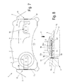
- Fig. 1 is a schematic sectional view of a first embodiment of a disc brake 1 according to the invention with a restoring device and an exemplary brake pad according to the invention 4 in a dissolved, ie unactuated position shown. This position is also referred to as the starting position.
- Fig. 2 shows the schematic partial sectional view to Fig. 2 with the brake pad 4 according to the invention in a tensioned or actuated position.
- the disc brake 1 is shown here in a partial view with a brake carrier 2, a brake disc 3 and the brake pad 4.
- a brake caliper engages over the brake disk 3, on which brake pads are arranged on both sides, of which only one brake pad 4 with a lining carrier 5 is partially shown.
- the brake pad 4 is arranged on the application side of the disc brake and the other brake lining, not shown, mounted on the other side of the brake disc 3 in the caliper.
- the caliper may for example be a sliding caliper.
- the disc brake 1 may e.g. be designed as a compressed air disc brake 1.
- the brake pad 4 is reversibly displaceably guided with its pad carrier 5 between guide surfaces 2a of the brake carrier 2 in a feed direction 7, which is marked with an arrow (see also Fig. 7 ).
- the feed direction 7 runs parallel to a rotational axis of the brake disk 3.
- a longitudinal direction of the lining carrier 5 extends tangentially to the brake disk 3, ie an imaginary line between the guide surfaces 2a, which is perpendicular to this. Perpendicular to this longitudinal direction, the lining carrier 5 extends in the radial direction of the brake disk 3.
- a brake disk friction surface 3a of the brake disk 3 faces a lining friction surface 4a of the brake lining 4.
- a distance between the brake pad or the brake pads and the brake disc is referred to as clearance 6.
- the clearance 6 is first bridged when the disc brake 1 is actuated, by the brake lining 4 being moved out of the starting position (FIG. Fig. 1 ) against the Brake disk 3 is applied in the feed direction 7. Due to the wear of the brake pads and the brake disc 3, the clearance increases 6th
- the restoring device is used to return the brake lining 4 from the applied position to the released position, ie to the starting position Fig. 1 so as to achieve a sufficient release of the brake pad 4 of the brake disc 3.
- the clearance 6 is restored.
- An adjustment of the brake pad 4 due to wear to adjust the clearance 6 to a predetermined value is made for example by an adjusting device, which will not be further explained here.
- the restoring device comprises in this embodiment, two return elements 10, which are attached to the pad backing of the brake pad 4, here on the back of the pad carrier 5.
- the back of the lining carrier 5 is the side of the lining carrier 5, which is facing away from the equipped with the brake pad 4 side of the lining carrier 5.
- Each return element 10 here is a spring element which is designed in the form of a leaf spring as a so-called claw spring with a claw edge 11 at an end region.
- the claw edge 11 is e.g. a sharp edge made by grinding or punching.
- This return element 10 is attached to the back of the pad carrier 5, that it presses with its bias against the brake pad back, so the back of the pad carrier 5.
- a return element 10 is in each case introduced into a groove-shaped recess 5b, which is arranged in each case on a lining carrier side 5a.
- the return element 10 rests against the lining carrier 5 with a large part of a back section 10f.
- the return element 10 is flush in this way with the surface of the back of the lining carrier 5, so that when the disc brake 1 is not actuated, no projection over the back of the lining carrier 5 occurs.
- Each recess 5b has an open end on each pad support side 5a facing the respective guide surface 2a.
- the return element 10 is provided with a fastening portion 10a in the region of the depression 5b pointing to the middle of the lining carrier 5 here with two fastening elements 19, eg rivets (here: flat rivets), which extend through fastening holes (see also FIG Fig. 3, 4 ), fastened.
- An attachment end 12 of the restoring element 10 is arranged in an end region of the depression 5b facing the center of the lining carrier 5.
- the other end of the return element 10 forms a return section 13, which protrudes slightly in the longitudinal direction of the brake pad 4 and the pad carrier 5 on the lining carrier side 5a to the circumferential support or guide surface 2a of the brake carrier 2 and with the claw edge 11 with the guide surface 2a of the brake carrier 2 is engaged.
- the return portion 13 of the return element 10 is connected via a spring portion 10 b (see Fig. 3 ) is connected to the attachment portion 10a and is formed bent, whereby the return end 13 is bent from the lining carrier 5 and protrudes counter to the feed direction 7.
- the spring portion 10b has an opening 14a, which is penetrated by a limiting element 20 acting as a stroke limiter.
- the limiting element 20 is here designed as a bolt with a guide section 20a and a head with a contact surface 20b and fastened in the lining carrier 5.
- the guide portion 20a penetrates the opening 14a of the return element 10 and has a length which limits the stroke of the spring portion 10b.
- the back portion 10f is fixed in the region of the attachment portion 10a and constantly on the lining carrier 5, while the back portion 10f extending to the return portion 13 abuts a region around the aperture 14a due to the biasing force in the recess 5b on the liner 5, but away therefrom can take off.
- the back section 10f in the region of the bent part, including the return section 13, does not rest on the lining carrier 5.
- this biasing force of the return element 10 acts restoring to the brake pad 4 and moves the same in his in Fig. 1 shown starting position back.
- the restoring element 10 applies due to its bias again with the lifted part of its back portion 10f to the back of the lining carrier 5.
- FIG. 3 shows a schematic longitudinal sectional view of an exemplary return element 10
- FIG. 4 shows a schematic plan view of the restoring element according to FIG. 10 Fig. 3 represents.
- the return element 10 after Fig. 3 is shown in a possible embodiment as a claw spring. From the in Fig. 3 Starting from the right-hand attachment end 12, the restoring element 10 extends to the left initially in the attachment portion 10a, which has two attachment holes 14 for the attachment elements 19. Here, the mounting holes 14 are formed as slots ( Fig. 4 ).
- the attachment portion 10a then passes over a downwardly extending arc portion 10c in the spring portion 10b, to which another, upwardly extending arc portion 10d connects, which forms the return portion 13 with the claw edge 11.
- the claw edge 11 is shown here only symbolically, it can of course be designed in different ways, such as a punched or sharply ground edge.
- the return portion 13 as end region of this embodiment of the claw spring is designed so that when dimensional tolerances sufficient elasticity exists to maintain a contact force of the claw edge 11 against the guide surface 2a of the brake carrier 2 within predetermined limits.
- the dot-dashed restoring portion 13 indicates the unstressed shape of the claw spring.
- the attachment end 12 is provided with an end radius 12a.
- the attachment end 12 can form a positive connection with the end of a depression 5b produced by a milling cutter, for example, when the end radius 12a is matched to that of the milling cutter.
- An embodiment of the claw spring may be configured such that a length 15 e.g. corresponds to 3.5 times a width 16 of the claw spring.
- the size of the attachment portion 10 a is determined by a Befest Nathanshack 17, which corresponds to the distance of the mounting holes 14 in the longitudinal direction of the claw spring, and by a Befest Trentshack 18, which is the distance from the attachment end 12 in the longitudinal direction of the claw spring to the nearest attachment hole 14.
- the fixing amount 17 may be e.g. be twice the Befestistrs horres 18.
- Fig. 5 is a schematic partial sectional view of the disc brake according to the invention with the restoring device shown with a variant of the exemplary brake pad 4 according to the invention in the starting position.
- Fig. 6 shows the schematic partial sectional view to Fig. 5 with the variant in a tensioned or actuated position.
- the lining carrier 5 has in this variant beveled lining carrier sides 5b, which correspond to a lining stopper guide 2b of the brake carrier 2, wherein the lining stopper 2b on the brake disk side unspecified lining stopper has.
- This variant with pad stoppers can be provided with the return device.
- the return element 10 of the embodiment is after Fig. 1, 2 attached here directly on the back of the lining carrier 5, for example, with not shown rivets as in Fig. 1, 2 ,
- the stroke limit of the return element 10 is also as in Fig. 1, 2 formed by means of the limiting element 20.
- the return portion 13 of the return element 10 is provided with the claw edge 11, wherein the reset function is already described above.
- the reset element 10 may also be arranged in a recess 5b, not shown here, of the lining carrier 5.
- Fig. 7 shows a schematic plan view of a lining carrier back another variant of the exemplary brake pad 4 according to the invention
- Fig. 8 shows an enlarged partial sectional view of the further variant Fig. 7 represents.
- the stroke limitation of the restoring element 10 can also be achieved in a simple manner in the case of pneumatically actuated disc brakes 1 with a mechanically acting wear adjustment system by a pressure element, e.g. zuspannfur, by a pressure piece 8 or a pressure plate, and the saddle side (reaction side) by the pressure surface of a saddle back 9 of the caliper, be realized.
- a lining carrier 5 of the brake pad 4 is shown within the guide surfaces 2a of the brake carrier 2.
- the feed direction 7 stands perpendicular to the plane of the drawing.
- a reset element 10 is after each Fig. 3, 4 attached. The attachment is not shown in detail, but easy to imagine.
- the return sections 13 of the two return elements 10 and these themselves are arranged approximately at half the length (perpendicular to the feed direction 7) of the guide surfaces 2a.
- the pressure piece 8 On the left in Fig. 7 the pressure piece 8 is indicated with two concentric circles on the return element 10. An enlarged partial sectional view of this area shows Fig. 8 , The return element 10 is received in the groove-shaped recess 5b of the lining carrier 5 on the lining carrier back and fastened with fastening elements 19. The return element 10 is thereby covered by an abutment portion 8a of the pressure piece 8 (pressure plate) so that only the standing with the guide surface 2a of the brake carrier 2 in contact end portion, here the spring portion 10b protrudes.
- the pressure piece 8 has a recess 8b, in which parts of the fastening elements 19 of the return element 10 can protrude freely.
- the depth of the return element 10 receiving groove-shaped recess 5b is dimensioned so that the brake pad 4 / pad carrier 5 can just perform the necessary power stroke upon actuation of the disc brake.
- This stroke is composed of the minimum clearance plus a maximum lining compression.
- the groove can extend in a wedge shape starting from the fastening points, ie from the fastening end 12 of the restoring element 10, in order to avoid unnecessary weakening of the lining carrier 5.
- the necessary groove depth of the recess 5b is present only in the end region, ie in the region of the spring section 10b of the return element 10.
- the contact surface of the pressure element 8 namely the abutment section 8a, reaches the region of the back section 10f of the spring section 10b of the restoring element 10 and displaces the restoring section against the clawing of the claw edge 11 on the guide surface 2a of the brake carrier 2 the amount of wear.
- the contact surface of the saddle back 9 interacts with the return elements of the reaction-side brake pad 4 / lining carrier 5.
- FIGS. 9 and 10 schematic partial sectional views of the disc brake 1 according to the invention with a still further variant of the exemplary brake pad 4 according to the invention in different positions.
- Fig. 9 the starting position is shown, and Fig. 10 represents the clamped position.
- the claw spring is designed as a restoring element 10 is also cranked, wherein the attachment portion 10a is connected via an oblique, bent and / or bent intermediate portion 10e with the spring portion 10b.
- the stroke limitation is designed as described above.
- the permissible minimum clearance per brake pad 4 is assumed to be 0.2 mm, for example.
- 0.5 mm data base compressibility measurement brake pad: for different brake pad qualities 250 ... 300 ⁇ m compression of the new brake pad 4 at a surface pressure of 500 N / cm 2 and brake pad temperature 400 ° C). This means that the minimum return stroke must be set at 0.8 mm.
- the lining compression resulting from low clamping force, completely worn brake linings and cold brake ( ⁇ 100 ° C) is ⁇ 0.1 mm.
- the maximum possible clearance resulting from wear in the case of a cold brake results from the difference between the constructively set return stroke of the claw spring, that is to say the return element 10, and the occurring lining compression. If the condition according to B) is used (0.1 mm compression, return stroke actuation 0.8 mm), the maximum possible clearance per brake pad 4 would be from 0 , 7 mm and thus set a maximum possible total clearance of 1.4 mm. However, since the total clearance of the brake is determined by the adjusting device of the brake, which is 0.8 mm according to the prerequisite met, the release stroke of the two brake pads 4 is limited by the caliper to this amount.
- the saddle-side brake pad 4 now also follows the restoring effect of the associated return elements 10. However, the brake caliper applied to this brake pad 4 must be moved against the frictional resistance of its sliding guide. Thus, the return elements 10 of the two saddle sides act against one another, wherein the force of the saddle-side return elements 10 is reduced by the friction resistance of the sliding guide of the saddle. The application-side restoring elements 10 can continue to expand and produce a larger return travel.
- the operating side brake pad 4 will perform its maximum possible return stroke and thus set a clearance on its side of 0.7 mm. This still leaves a clearance of 0.1 mm on the saddle-side lining.
- the saddle-side return elements 10 are equipped with a correspondingly higher restoring force.
- the return elements 10 are equipped as Krallfedern both brake pads 4 with a stiff characteristic, which causes the return element 10 recorded with the larger stroke a greater force drop, creating a clearance compensating effect is achieved. Due to the spring force tolerances and the scattering of the frictional resistance of the sliding guide unequal clearance will still set. However, this is not of course, as long as a minimum clearance is guaranteed on both sides.
- the claw edge 11 at least partially has a toothing with tooth tips for the claw function.
- the claw edge 11 can also be hardened.
Abstract
Description
Die Erfindung betrifft eine Scheibenbremse, insbesondere für ein Kraftfahrzeug, nach dem Oberbegriff des Anspruchs 1. Die Erfindung bezieht sich auch auf einen entsprechenden Bremsbelag.The invention relates to a disc brake, in particular for a motor vehicle, according to the preamble of
Derartige Scheibenbremsen sind üblicherweise druckluftbetätigt und mit automatisch wirkenden, mechanischen Belagverschleißnachstellvorrichtungen ausgestattet. Diese Belagverschleißnachstellvorrichtungen verkleinern ein zu groß gewordenes Lüftspiel.Such disc brakes are usually pneumatically operated and equipped with automatically acting, mechanical pad wear adjustment devices. These lining wear adjusting devices reduce the clearance that has become too large.
Restschleifmomente der Radbremsen, insbesondere von Scheibenbremsen, können bei kombinierten Schwerlastfahrzeugen bis zu 1 % höheren Kraftstoffverbrauch führen. Darüber hinaus tritt infolge des ständigen Schleifens der Bremsbeläge ein erhöhter Bremsbelagverschleiß ein, wodurch die Wartungskosten des Fahrzeugs erhöht werden. Ursache dieser Restschleifmomente ist ein nicht vollständiges Lösen der Bremsbeläge von der Bremsscheibe nach einem Bremsvorgang.Residual grinding torques of the wheel brakes, especially disk brakes, can lead to up to 1% higher fuel consumption in combined heavy-duty vehicles. In addition, due to the constant grinding of the brake pads, increased brake pad wear occurs, thereby increasing the maintenance cost of the vehicle. The cause of these residual grinding moments is not complete release of the brake pads from the brake disc after a braking operation.
Zur Vermeidung dieser Restschleifmomente ist es erforderlich, beim Lösen der Bremse nach einer vorhergehenden Bremsung durch aktives Zurückziehen der Bremsbeläge einen Mindestluftspalt (Mindestlüftspiel) zwischen den Reibflächen der Bremsbeläge und der Bremsscheibenreibfläche herzustellen. Hierzu sind unterschiedliche Methoden bekannt.To avoid these residual grinding moments, it is necessary to produce a minimum air gap (minimum clearance) between the friction surfaces of the brake linings and the Bremsscheibenreibfläche when releasing the brake after a previous braking by active retraction of the brake pads. For this purpose, different methods are known.
Bei Festsattel-Scheibenbremsen, welche eine feststehende Position von Bremssattel und Bremsscheibe aufweisen, ist es ausreichend, die Bremsbeläge mit dem auf den jeweiligen Bremsbelag einwirkenden Betätigungskolben so zu verbinden, dass die Betätigungskolben beim Lösen der Bremse die Bremsbeläge in ihrer Rückzugbewegung mitnehmen und auf diese Weise das Lüftspiel zwischen Bremsbelägen und Bremsscheibe wiederherstellen. Mit dieser Maßnahme ist bei Festsattel-Scheibenbremsen eine weitgehende Vermeidung von Restschleifmomenten möglich.In fixed-caliper disc brakes, which have a fixed position of caliper and brake disc, it is sufficient to connect the brake pads with the force acting on the respective brake pad actuating piston so that the actuating piston when releasing the brake, the brake pads in their retracting move and in this way Restore the clearance between brake pads and brake disc. With this measure, it is possible to largely avoid residual grinding torques for fixed caliper disc brakes.
Bei Schiebesattel-Scheibenbremsen kann dagegen ein ausreichendes Lösen der Bremsbeläge nicht allein durch eine rückzugsfähige Anbindung derselben an die Betätigungskolben bzw. an den Sattelrücken erzielt werden, da der Bremssattel in seiner Schiebeführung frei beweglich bleibt. Das kann dazu führen, dass einer der beiden Bremsbeläge, in der Regel der sattelseitige Bremsbelag, noch mit der Bremsscheibe in Schleifkontakt bleibt.With sliding caliper disc brakes, however, sufficient release of the brake pads can not be achieved solely by a retractable connection of the same to the actuating piston or to the saddle back, since the caliper in his Sliding guide remains free to move. This can lead to one of the two brake linings, usually the saddle-side brake pad, remaining in sliding contact with the brake disc.
Bei Schiebesattel-Scheibenbremsen wird deshalb in Betracht gezogen, dem Bremssattel im nicht betätigten Zustand mit Hilfe von an den Schiebführungen angeordneten Klemmelementen eine quasi fixe Position zu geben, wodurch eine beidseitige Lüftspieleinstellung ermöglicht wird. Dies illustriert
Auch diese einfach und praktikabel erscheinende Methode hat keine nennenswerte Anwendung gefunden. Die Klemmelemente können anfällig für Verschmutzung und Korrosion sein. Bei auftretenden Vibrationen können sie starken Belastungen durch den Bremsbelag ausgesetzt sein. Zudem können die Klemmelemente durch Festrosten/Blockieren die Wirkung der Bremse beeinträchtigen. Für die Anwendung in schweren Nutzfahrzeugen ist diese Lösung deshalb nicht geeignet.This simple and practicable method has found no appreciable application. The clamping elements can be susceptible to contamination and corrosion. When vibrations occur, they can be exposed to heavy loads through the brake pad. In addition, the clamping elements can affect the effect of the brake by solid rust / blocking. For use in heavy commercial vehicles, this solution is therefore not suitable.
Die Aufgabe der vorliegenden Erfindung besteht darin, eine verbesserte Scheibenbremse zu schaffen.The object of the present invention is to provide an improved disc brake.
Eine weitere Aufgabe ist es, einen verbesserten Bremsbelag für eine Scheibenbremse bereitzustellen.Another object is to provide an improved brake pad for a disc brake.
Die Aufgabe wird durch eine Scheibenbremse mit den Merkmalen des Anspruchs 1, und einen Bremsbelag mit den Merkmalen des Anspruchs 12 gelöst.The object is achieved by a disc brake with the features of
Die erfindungsgemäße Scheibenbremse weist jeweils eine Rückstelleinrichtung für jeden Bremsbelag auf, deren Lösefunktion nicht durch den Bremssattel beeinflusst wird. Die Rückstelleinrichtungen weisen einen einfachen Aufbau und hohe Robustheit auf. Eine Störung in der Wirkung der Rückstelleinrichtungen ruft keine Beeinflussung der Scheibenbremse hervor. Die Scheibenbremse kann druckluftbetätigt sein und ist besonders für schwere Nutzfahrzeuge geeignet, wobei Restschleifmomente und unnötiger Bremsbelagverschleiß vermieden wird.The disc brake according to the invention in each case has a restoring device for each brake pad whose release function is not influenced by the brake caliper. The reset devices have a simple structure and high robustness. A disturbance in the action of the restoring means does not cause any influence on the disc brake. The disc brake can be compressed air actuated and is particularly suitable for heavy commercial vehicles, with residual grinding moments and unnecessary brake pad wear is avoided.
Eine erfindungsgemäße Scheibenbremse insbesondere für ein Kraftfahrzeug, umfasst eine Zuspannvorrichtung, einen eine Bremsscheibe übergreifenden Bremssattel, insbesondere ein Schiebesattel, vorzugsweise eine Belagverschleißnachstellvorrichtung, einen Bremsträger mit in Umfangsrichtung der Bremsscheibe gegenüberliegenden Führungsflächen, zwischen welchen beidseitig der Bremsscheibe jeweils mindestens ein Bremsbelag mit einem Belagträger parallel zu einer Drehachse der Bremsscheibe verschiebbar geführt und von einer Zuspannkraft betätigbar ist, und jeweils eine Rückstelleinrichtung, welche den jeweils mindestens einen Bremsbelag mit dem Belagträger mit jeweils mindestens einem Rückstellabschnitt an jeder Führungsfläche abstützt. Jede Rückstelleinrichtung umfasst mindestens zwei Rückstellelemente, die an dem Rücken des Belagträgers des jeweils mindestens einen Bremsbelags angebracht sind.A disc brake according to the invention, in particular for a motor vehicle, comprises a brake application device, a brake caliper, in particular a sliding caliper, preferably a lining wear adjusting device, a brake carrier with guide surfaces located in the circumferential direction of the brake disc, between each of which at least one brake pad with a lining carrier parallel to both sides of the brake disc an axis of rotation of the brake disc is displaceably guided and actuated by a clamping force, and in each case a restoring device, which supports the respective at least one brake pad with the lining carrier, each having at least one return portion on each guide surface. Each restoring device comprises at least two restoring elements, which are attached to the back of the lining carrier of the respective at least one brake pad.
Durch die Anwendung geeigneter Rückstellelemente können weitere störanfällige Bauteile, wie z.B. Klemmelemente, vermieden werden und die Bauteilanzahl wird verringert.By using suitable restoring elements, further components susceptible to failure, such as, for example, Clamping elements are avoided and the number of components is reduced.
Weitere vorteilhafte Ausgestaltungen sind in den Unteransprüchen angegeben.Further advantageous embodiments are specified in the subclaims.
Es ist vorgesehen, dass jedes der mindestens zwei Rückstellelemente den jeweils mindestens einen Rückstellabschnitt aufweist. Dabei werden keine Zusatzbauteile benötigt.It is provided that each of the at least two return elements has the respective at least one return section. No additional components are needed.
In einer Ausführung ist jedes der mindestens zwei Rückstellelemente mit einem Befestigungsabschnitt und einem Federabschnitt ausgebildet, wobei der Federabschnitt an seinem freien Ende den Rückstellabschnitt aufweist. Das Rückstellelement kann somit auch ein Federarm sein. Ein oder mehrere Federarme, vorzugsweise Blattfedern, sind am Bremsbelagträger oder Bremsbelagrücken befestigt.In one embodiment, each of the at least two restoring elements is formed with a fixing portion and a spring portion, wherein the spring portion has the return portion at its free end. The return element can thus also be a spring arm. One or more spring arms, preferably leaf springs, are attached to the brake pad carrier or brake pad backs.
In einer weiteren Ausführung ist der Rückstellabschnitt mit einer scharfen Kante als Krallkante ausgebildet. Zudem ragt der mindestens eine Rückstellabschnitt jedes Rückstellelementes in Längsrichtung des Belagträgers über eine Belagträgerseite geringfügig zu der jeweiligen Führungsfläche des Bremsträgers hinaus und steht mit der Krallkante mit der Führungsfläche des Bremsträgers in Eingriff.In a further embodiment, the return section is formed with a sharp edge as a claw edge. In addition, the at least one return section of each restoring element projects slightly beyond the respective guide surface of the brake carrier in the longitudinal direction of the lining carrier via a lining carrier side and engages with the claw edge with the guide surface of the brake carrier.
Die Federarme werden durch ihre Spannkraft mit dem hinausragenden Überstand gegenüber den umfangsseitigen Abstützflächen des Rückens des Belagträgers an die Führungsflächen des Bremsträgers angepresst und verkrallen sich mit der Krallkante gegen diese Führungsflächen zur Abstützung von Rückzugskräften.The spring arms are pressed by their clamping force with the protruding projection with respect to the circumferential support surfaces of the back of the pad carrier to the guide surfaces of the brake carrier and digs with the claw edge against these guide surfaces to support withdrawal forces.
In einer weiteren Ausführung ist jedes der mindestens zwei Rückstellelemente mit dem Befestigungsabschnitt auf dem Belagträger befestigt, und der Federabschnitt steht mindestens teilweise von dem Belagträger federnd hervor. Die Federarme, d.h. die Rückstellelemente, sind mit einer Vorspannkraft gegen den Rücken des Belagträgers angelegt, so dass, wenn bei Betätigung der Bremse der Bremsbelag verschoben wird, dieser von dem an den Führungsflächen des Bremsträgers verkrallten Rückstellabschnitt unter Überwindung der Vorspannkraft abhebt.In a further embodiment, each of the at least two restoring elements is secured to the mounting portion on the lining carrier, and the spring portion is at least partially resiliently protruding from the lining carrier. The spring arms, i. the return elements, are applied with a biasing force against the back of the pad carrier, so that when the brake pad is moved upon actuation of the brake, this lifts off from the verkrallten on the guide surfaces of the brake carrier return section, overcoming the biasing force.
Nach Beendigung des Bremsvorgangs bzw. der Zuspannung der Bremse wirkt diese Vorspannkraft rückstellend auf den Bremsbelag und bewegt diesen, unter Wiederherstellung eines Lüftspiels zwischen Bremsbelag und Bremsscheibe, in seine Ausgangsposition zurück.After completion of the braking process or the application of the brake, this biasing force restoring acts on the brake pad and moves it, restoring a clearance between brake pad and brake disc, back to its original position.
In einer anderen Ausführung ist vorgesehen, dass eine Hubbewegung einer möglichen Ausfederung des Federabschnitts durch ein Begrenzungselement, ein Druckstück, eine Druckplatte oder einen Sattelrücken begrenzt ist. Damit kann die Hubbewegung einer möglichen Ausfederung des Federabschnitts auf einen maximal erforderlichen Arbeitshub des Bremsbelags begrenzt werden. Der maximal erforderliche Arbeitshub des Bremsbelags ist das Lüftspiel plus eine Belagverpressung.In another embodiment, it is provided that a lifting movement of a possible rebound of the spring section is limited by a limiting element, a pressure piece, a pressure plate or saddle back. Thus, the lifting movement of a possible rebound of the spring portion can be limited to a maximum required working stroke of the brake pad. The maximum required working stroke of the brake lining is the clearance plus a lining compression.
In einer noch anderen Ausführung ist jedes der mindestens zwei Rückstellelemente in einer Vertiefung des Belagträgers angeordnet. So kann bei nicht betätigter Bremse kein Überstand über den Belagrücken auftreten.In yet another embodiment, each of the at least two restoring elements is arranged in a recess of the lining carrier. Thus, when the brake is not actuated, no protrusion over the pad back can occur.
In einer weiteren Ausführung weisen die Rückstelleinrichtungen auf unterschiedlichen Seiten der Bremsscheibe unterschiedlich hohe Rückstellkräfte auf. Daraus kann sich eine gleichmäßige Aufteilung der beidseitigen Lüftspiele ergeben. Außerdem können z.B. die Rückstellelemente als Krallfedern zusätzlich auch mit unterschiedlicher steifer Charakteristik ausgebildet sein. Dies ermöglicht, dass das Rückstellelement mit dem größeren Hub einen stärkeren Kräfteabfall verzeichnet, wodurch eine die Lüftspiele ausgleichende Wirkung auftritt.In a further embodiment, the restoring devices have different high restoring forces on different sides of the brake disk. This can result in a uniform distribution of the two-sided airs. In addition, e.g. the restoring elements may be additionally designed as claw springs with different stiff characteristics. This allows the return element with the larger stroke recorded a greater drop in power, creating a clearance compensating effect occurs.
Die Scheibenbremse kann druckluftbetätigt sein.The disc brake can be pneumatically operated.
Ein entsprechender Bremsbelag einer Scheibenbremse ist mit einer oben beschriebenen Rückstelleinrichtung ausgestattet.A corresponding brake pad of a disc brake is equipped with a restoring device described above.
Die Erfindung wird nun anhand beispielhafter Ausführungen mit Bezug auf die beigefügten Zeichnungen näher erläutert. Hierbei zeigen:
- Fig. 1-2
- schematische Teilschnittansichten eines Ausführungsbeispiels einer erfindungsgemäßen Scheibenbremse mit einer Rückstelleinrichtung und einem beispielhaften erfindungsgemäßen Bremsbelag in verschiedenen Stellungen;
- Fig. 3
- eine schematische Längsschnittansicht eines beispielhaften Rückstellelementes;
- Fig. 4
- eine schematische Draufsicht des Rückstellelementes nach
Fig. 3 ; - Fig. 5-6
- schematische Teilschnittansichten der erfindungsgemäßen Scheibenbremse mit einer Variante des beispielhaften erfindungsgemäßen Bremsbelags in verschiedenen Stellungen;
- Fig. 7
- eine schematische Draufsicht auf einen Belagträgerrücken einer weiteren Variante des beispielhaften erfindungsgemäßen Bremsbelags;
- Fig. 8
- eine vergrößerte Teilschnittansicht der weiteren Variante nach
Fig. 7 ; und - Fig. 9-10
- schematische Teilschnittansichten der erfindungsgemäßen Scheibenbremse mit einer noch weiteren Variante des beispielhaften erfindungsgemäßen Bremsbelags in verschiedenen Stellungen.
- Fig. 1-2
- schematic partial sectional views of an embodiment of a disc brake according to the invention with a restoring device and an exemplary brake pad according to the invention in different positions;
- Fig. 3
- a schematic longitudinal sectional view of an exemplary return element;
- Fig. 4
- a schematic plan view of the return element after
Fig. 3 ; - Fig. 5-6
- schematic partial sectional views of the disc brake according to the invention with a variant of the exemplary brake pad according to the invention in different positions;
- Fig. 7
- a schematic plan view of a lining carrier back another variant of the exemplary brake pad according to the invention;
- Fig. 8
- an enlarged partial sectional view of the further variant according to
Fig. 7 ; and - Fig. 9-10
- schematic partial sectional views of the disc brake according to the invention with a still further variant of the exemplary brake pad according to the invention in different positions.
In
Die Scheibenbremse 1 ist hier in einer Teilansicht mit einem Bremsträger 2, einer Bremsscheibe 3 und dem Bremsbelag 4 gezeigt. Ein nicht gezeigter Bremssattel übergreift die Bremsscheibe 3, an welcher beidseitig Bremsbeläge angeordnet sind, von denen nur der eine Bremsbelag 4 mit einem Belagträger 5 zum Teil dargestellt ist. Beispielsweise ist der Bremsbelag 4 auf der Zuspannseite der Scheibenbremse angeordnet und der andere nicht gezeigte Bremsbelag auf der anderen Seite der Bremsscheibe 3 im Bremssattel angebracht. Der Bremssattel kann beispielsweise ein Schiebesattel sein. Die Scheibenbremse 1 kann z.B. als druckluftbetätigte Scheibenbremse 1 ausgeführt sein.The
Die Darstellungen und Ausführungen hinsichtlich des Bremsbelags 4 gelten somit auch für den nicht gezeigten anderen Bremsbelag der Scheibenbremse 1, was leicht vorstellbar ist.The illustrations and embodiments with respect to the
Der Bremsbelag 4 ist mit seinem Belagträger 5 zwischen Führungsflächen 2a des Bremsträgers 2 in einer Zustellrichtung 7, die mit einem Pfeil gekennzeichnet ist, reversibel verschiebbar geführt (siehe auch
Eine Bremsscheibenreibfläche 3a der Bremsscheibe 3 steht einer Belagreibfläche 4a des Bremsbelags 4 gegenüber. Ein Abstand zwischen dem Bremsbelag bzw. den Bremsbelägen und der Bremsscheibe wird als Lüftspiel 6 bezeichnet. Bei einem Bremsvorgang wird bei Betätigung der Scheibenbremse 1 zunächst das Lüftspiel 6 überbrückt, indem der Bremsbelag 4 aus der Ausgangsposition (
Beim zugespannten Bremsbelag 4 ist das Lüftspiel 6 zu Null geworden, wobei der Bremsbelag 4 an der Bremsscheibe 3 der Scheibenbremse 1 anliegt. Das Lüftspiel 6 ist in dieser zugespannten Stellung, die
Die Rückstelleinrichtung dient zur Rückstellung des Bremsbelags 4 aus der zugespannten Stellung in die gelöste Stellung, d.h. in die Ausgangsposition nach
Die Rückstelleinrichtung umfasst in diesem Ausführungsbeispiel zwei Rückstellelemente 10, die an dem Belagrücken des Bremsbelags 4, hier an dem Rücken des Belagträgers 5 angebracht sind. Der Rücken des Belagträgers 5 ist die Seite des Belagträgers 5, welche der mit dem Bremsbelag 4 bestückten Seite des Belagträgers 5 abgewandt ist. Jedes Rückstellelement 10 ist hier ein Federelement, das in Gestalt einer Blattfeder als eine so genannte Krallfeder mit einer Krallkante 11 an einem Endbereich ausgebildet ist. Die Krallkante 11 ist z.B. eine scharfe Kante, die durch Schleifen oder Stanzen hergestellt ist.The restoring device comprises in this embodiment, two
Dieses Rückstellelement 10 ist so an dem Rücken des Belagträgers 5 befestigt, dass es mit seiner Vorspannung gegen den Bremsbelagrücken, also den Rücken des Belagträgers 5 drückt. In dem in
Jede Vertiefung 5b weist ein offenes Ende an jeder Belagträgerseite 5a auf, das zur jeweiligen Führungsfläche 2a weist. Das Rückstellelement 10 ist mit einem Befestigungsabschnitt 10a in dem zur Mitte des Belagträgers 5 weisenden Bereich der Vertiefung 5b hier mit zwei Befestigungselementen 19, z.B. Nieten (hier: Flachnieten), die sich durch Befestigungslöcher erstrecken (siehe auch
Der Rückstellabschnitt 13 des Rückstellelementes 10 ist über einen Federabschnitt 10b (siehe
Der Rückenabschnitt 10f liegt im Bereich des Befestigungsabschnitts 10a fest und ständig an dem Belagträger 5 an, während der sich zum Rückstellabschnitt 13 erstreckende Rückenabschnitt 10f in einen Bereich um den Durchbruch 14a herum aufgrund der Vorspannkraft in der Vertiefung 5b am Belagträger 5 anliegt, aber sich davon abheben kann. Der Rückenabschnitt 10f im Bereich des abgebogenen Teils einschließlich des Rückstellabschnitts 13 liegt nicht am Belagträger 5 an.The
In der unbetätigten Stellung nach
Bei Zuspannung bzw. Betätigung der Scheibenbremse 1 wird der Bremsbelag 4 (einschließlich Belagträger 5) in Zustellrichtung 7 in Richtung Bremsscheibe 3 verschoben, während die Krallkante 11 des Rückstellelementes 10 unter Einwirkung einer Vorspannkraft des Rückstellelementes 10 an der Führungsfläche 2a des Bremsträgers 2 gehalten wird, was in
Nach der Bremsbetätigung wirkt diese Vorspannkraft des Rückstellelementes 10 rückstellend auf den Bremsbelag 4 und bewegt denselben in seine in
Nun wird eine Rückstellfunktion der Rückstelleinrichtung beschrieben. Wenn bei einem aufgetretenen Bremsenverschleiß der ausgeführte Hub des Bremsbelags 4 den Betrag eines Mindestlüftspiels plus maximal möglicher Belagverpressung übersteigt, rutscht der Rückstellabschnitt 13 mit der Krallkante 11 des Rückstellelementes 10 unter Einwirkung der Zuspannkraft der Scheibenbremse 1 um den Betrag des aufgetretenen Verschleißes weiter in Zustellrichtung 7 und nimmt eine neue Ausgangsposition ein. D.h., die neue Ausgangsposition des Bremsbelags 4 befindet sich in Zustellrichtung 7 näher an der Bremsscheibe 3.Now, a reset function of the return device will be described. If at an occurred brake wear of the executed stroke of the
Das Rückstellelement 10 nach
Der Befestigungsabschnitt 10a geht dann über einen nach unten verlaufenden Bogenabschnitt 10c in den Federabschnitt 10b über, an den sich ein weiterer, nach oben verlaufender Bogenabschnitt 10d anschließt, welcher den Rückstellabschnitt 13 mit der Krallkante 11 bildet. Die Krallkante 11 ist hier nur symbolisch dargestellt, sie kann natürlich auf unterschiedliche Art ausgebildet sein, z.B. eine gestanzte oder scharf geschliffene Kante.The
Der Rückstellabschnitt 13 als Endbereich dieser Ausführungsform der Krallfeder ist dabei so gestaltet, dass bei Auftreten von Maßtoleranzen eine ausreichende Elastizität besteht, um eine Anpresskraft der Krallkante 11 gegen die Führungsfläche 2a des Bremsträgers 2 in vorgegebenen Grenzen aufrechtzuerhalten.The
Der strichpunktiert gezeichnete Rückstellabschnitt 13 deutet die ungespannte Form der Krallfeder an.The dot-dashed restoring
In
Ein Ausführungsbeispiel der Krallfeder kann so ausgestaltet sein, dass eine Länge 15 z.B. dem 3,5fachen einer Breite 16 der Krallfeder entspricht. Die Größe des Befestigungsabschnitts 10a ist durch ein Befestigungsmaß 17, das dem Abstand der Befestigungslöcher 14 in Längsrichtung der Krallfeder entspricht, und durch ein Befestigungsmaß 18, welches der Abstand vom Befestigungsende 12 in Längsrichtung der Krallfeder zum nächstliegenden Befestigungsloch 14 ist, festlegt. Dabei kann das Befestigungsmaß 17 z.B. das Doppelte des Befestigungsmaßes 18 betragen.An embodiment of the claw spring may be configured such that a
In
Der Belagträger 5 weist in dieser Variante abgeschrägte Belagträgerseiten 5b auf, welche mit einer Belagstopperführung 2b des Bremsträgers 2 korrespondieren, wobei die Belagstopperführung 2b bremsscheibenseitig nicht näher bezeichnete Belagstopper aufweist. Auch diese Variante mit Belagstoppern kann mit der Rückstelleinrichtung versehen werden. Dazu ist das Rückstellelement 10 des Ausführungsbeispiels nach
Die Hubbegrenzung des Rückstellelementes 10 kann bei druckluftbetätigten Scheibenbremsen 1 mit einem mechanisch wirkenden Verschleißnachstellsystem auch auf eine einfache Weise durch ein Druckelement, z.B. zuspannseitig, durch ein Druckstück 8 oder eine Druckplatte, und sattelseitig (reaktionsseitig) durch die Andruckfläche eines Sattelrückens 9 des Bremssattels, realisiert sein.The stroke limitation of the restoring
In
Auf der linken Seite in
In ähnlicher Weise gilt dies für die Sattelandruckfläche des Sattelrückens 9, der auf der rechten Seite der
Die Tiefe der das Rückstellelement 10 aufnehmenden nutförmigen Vertiefung 5b ist so bemessen, dass der Bremsbelag 4/Belagträger 5 bei Betätigung der Scheibenbremse 1 gerade den notwendigen Arbeitshub ausführen kann. Dieser Arbeitshub setzt sich zusammen aus dem Mindestlüftspiel plus einer maximalen Belagverpressung. Die Nut kann in einer Ausführung von den Befestigungsstellen, d.h. vom Befestigungsende 12 des Rückstellelementes 10, ausgehend keilförmig verlaufen, um eine unnötige Schwächung des Belagträgers 5 zu vermeiden. Dabei liegt die notwendige Nuttiefe der Vertiefung 5b nur im Endbereich, d.h. im Bereich des Federabschnitts 10b des Rückstellelementes 10 vor.The depth of the
Bei Überschreiten dieses notwendigen Arbeitshubes im Fall von eingetretenem Verschleiß erreicht die Anlagefläche des Druckstücks 8, nämlich der Anlageabschnitt 8a den Bereich des Rückenabschnitts 10f des Federabschnitts 10b des Rückstellelementes 10 und verschiebt den Rückstellabschnitt gegen die Verkrallung der Krallkante 11 an der Führungsfläche 2a des Bremsträgers 2 um den Betrag des Verschleißes. In gleicher Weise wirkt die die Anlagefläche des Sattelrückens 9 mit den Rückstellelementen des reaktionsseitigen Bremsbelags 4/Belagträger 5 zusammen.When this necessary working stroke is exceeded in the event of wear, the contact surface of the
Schließlich zeigen
In dieser Variante mit Belagstopper sind hier im Unterschied zu der Variante nach
Nachfolgend wird der mindest notwendige, durch die Rückstelleinrichtung zu bewirkende Rückstellungshub oder Rückhub des Bremsbelags 4 für unterschiedliche Betriebszustände der Scheibenbremse 1 beispielhaft beschrieben. Die unterschiedlichen Anforderungen werden im Wesentlichen durch die je nach Verschleiß und Betriebszustand unterschiedliche Belagverpressung bestimmt.Subsequently, the minimum necessary, to be effected by the return means Rückstellungshub or return stroke of the
Das zulässige Mindestlüftspiel pro Bremsbelag 4 wird z.B. mit 0,2 mm angenommen. Die bei maximaler Zuspannkraft erzeugte Belagverpressung beträgt bei hohen Betriebstemperaturen und unverschlissenem Bremsbelag 4 ca. 0,5 mm (Datenbasis Kompressibilitätsmessung Bremsbelag: Für verschiedene Bremsbelagqualitäten 250...300 µm Verpressung des neuen Bremsbelags 4 bei einer Flächenpressung von 500 N/cm2 und Bremsbelagtemperatur 400°C). D.h., dass der Mindestrückhub mit 0,8 mm anzusetzen ist.The permissible minimum clearance per
Die bei geringer Zuspannkraft, vollständig verschlissenen Bremsbelägen und kalter Bremse (<100 °C) entstehende Belagverpressung beträgt <0,1 mm.The lining compression resulting from low clamping force, completely worn brake linings and cold brake (<100 ° C) is <0.1 mm.
Es können drei Extremzustände angenommen werden:
- A)
Neuzustand der Bremsbeläge 4 und Bremsbelagtemperatur 400°C ⇒ Mindestrückhub 0,8 mm - B)
Vollverschlissene Bremsbeläge 4 und Bremsbelagtemperatur <100 °C ⇒ Mindestrückhub 0,3 mm - C)
Neuzustand der Bremsbeläge 4 und Bremsbelagtemperatur 100°C Zustand der abgekühlten Scheibenbremse 1 nach einer Bremsung wie unter A) beschrieben.
- A) New condition of
brake pads 4 and brake pad temperature 400 ° C ⇒ Minimum return stroke 0.8 mm - B) Fully worn
brake pads 4 and brake pad temperature <100 ° C ⇒ Minimum return stroke 0.3 mm - C) Condition of the
brake pads 4 and brake pad temperature 100 ° C state of the cooleddisc brake 1 after braking as described under A).
Zu A):
- Ablauf einer Bremsung mit 400°C Bremsbelagtemperatur und maximaler Bremsbelagdicke
- a) am sattelseitigen Bremsbelag 4 (LS = Lüftspiel; VP = Verpressung)
Ausgangszustand:LS
Betätigungshub: 0,4 mm LS + 0,5 mm VP = 0,9 mm
=> Die Krallfeder (Rückstellelement 10) rutscht 0,1 mmnach Rückhub Bremsbelag 4 0,8 mm: Das neueLüftspiel ist mit
⇒ Die Sattelposition ist um 0,1 mm zur Fahrzeuginnenseite verschoben. - b) am zuspannseitigen Bremsbelag 4 (LS = Lüftspiel; VP = Verpressung)
Ausgangszustand:LS
Betätigungshub: 0,4 mm LS + 0,5 mm VP = 0,9mm
⇒ Die Krallfeder (Rückstellelement 10) rutscht 0,1 mmnach Rückhub Bremsbelag 4 0,8 mm: Das neueLüftspiel ist mit
⇒ Die Sattelposition ist um 0,1 mm zur Fahrzeuginnenseite verschoben.Rückhub Betätigung
⇒ Aus der Rückhubdifferenz und der eingetretenen Veränderung der Sattelposition ergibt sich ein Spiel zwischen Belagrücken (Rücken des Belagträgers 5) und Druckstücken 8von
⇒ Das Gesamtlüftspiel LS gesamt ergibt sich aus: LS außen + LS innen + LS Druckstück zu:
⇒ LS gesamt = 0,3 + 0,3 + 0,2 = 0,8 mm (Ausgangs-Gesamtlüftspiel)
- a) am sattelseitigen Bremsbelag 4 (LS = Lüftspiel; VP = Verpressung)
- Process of braking with 400 ° C brake lining temperature and maximum brake pad thickness
- a) on the saddle-side brake pad 4 (LS = clearance, VP = compression)
Initial state: LS 0.4 mm
Actuation stroke: 0.4 mm LS + 0.5 mm VP = 0.9 mm
=> The claw spring (return element 10) slips 0.1 mm after returnstroke Brake lining 4 0.8 mm: The new clearance is set at 0.3 mm.
⇒ The saddle position is shifted by 0.1 mm to the vehicle inside. - b) on the application-side brake pad 4 (LS = clearance; VP = compression)
Initial state: LS 0.4 mm
Actuation stroke: 0.4 mm LS + 0.5 mm VP = 0.9mm
⇒ The claw spring (return element 10) slips 0.1 mm after returnstroke Brake lining 4 0.8 mm: The new clearance is set at 0.3 mm.
⇒ The saddle position is shifted by 0.1 mm to the vehicle inside. Return stroke actuation 0.9 mm
⇒ From the return stroke difference and the change occurred in the saddle position results in a game between the pad backing (back of the pad carrier 5) andpressure pieces 8 of 0.2 mm.
⇒ The total clearance LS total results from: LS outside + LS inside + LS pressure piece to:
⇒ LS total = 0.3 + 0.3 + 0.2 = 0.8 mm (initial total clearance)
- a) on the saddle-side brake pad 4 (LS = clearance, VP = compression)
Zu B):
- Ablauf einer Bremsung mit kaltem und vollständig verschlissenem Bremsbelag 4
- a) am sattelseitigen Bremsbelag 4 (LS = Lüftspiel; VP = Verpressung)
Ausgangszustand:LS
Betätigungshub: 0,4 mm LS + 0,1 mm VP = 0,5 mm
⇒ Der Betätigungshub ist kleiner als der an der Krallfeder eingestellte Maximalhub. D.h. die Krallfeder erreicht ihre Hubbegrenzung nicht. Es tritt kein Weiterrutschen der Krallfeder auf und damit auch keine Veränderung der Sattelposition.
⇒ Rückhub
⇒ Neues Lüftspiel
⇒ Die Sattelposition bleibt erhalten. - b) am zuspannseitigen Bremsbelag 4 (LS = Lüftspiel; VP = Verpressung)
Ausgangszustand:LS
Betätigungshub: 0,4 mm LS + 0,1 mm VP = 0,5 mm
⇒ Anmerkung siehe oben unter a)
⇒ Rückhub
⇒ Neues Lüftspiel
⇒ Es entsteht kein zusätzliches Spiel zwischen Rücken desBelagträgers 5 und Druckstücken 8sowie Sattelrücken 9.
- a) am sattelseitigen Bremsbelag 4 (LS = Lüftspiel; VP = Verpressung)
- Process of braking with cold and completely
worn brake pad 4- a) on the saddle-side brake pad 4 (LS = clearance, VP = compression)
Initial state: LS 0.4 mm
Actuation stroke: 0.4 mm LS + 0.1 mm VP = 0.5 mm
⇒ The actuating stroke is smaller than the maximum stroke set on the claw spring. That is, the claw spring does not reach its stroke limit. There is no further slippage of the claw spring and thus no change in the saddle position.
⇒ return stroke 0.5 mm
⇒ new clearance 0.4 mm = initial clearance
⇒ The saddle position is retained. - b) on the application-side brake pad 4 (LS = clearance; VP = compression)
Initial state: LS 0.4 mm
Actuation stroke: 0.4 mm LS + 0.1 mm VP = 0.5 mm
⇒ note see above under a)
⇒ return stroke 0.5 mm
⇒ new clearance 0.4 mm = initial clearance
⇒ There is no additional play between the back of thelining carrier 5 andpressure pieces 8 and saddle back 9.
- a) on the saddle-side brake pad 4 (LS = clearance, VP = compression)
Fazit
Eine Veränderung des Lüftspiels tritt nur ein, wenn die Belagverpressung größer ist als die Differenz aus konstruktiv vorgehaltenem Rückhub minus dem vor der Bremsbetätigung tatsächlich vorhandenem Lüftspiel.Conclusion
A change in the clearance occurs only when the lining compression is greater than the difference from structurally held return stroke minus the actual before the brake actuation clearance.
Zu C):
- Ablauf einer Bremsung im Zustand nach der unter A) beschriebenen Bremsung
- a) sattelseitiger Bremsbelag (LS = Lüftspiel; VP = Verpressung)
Ausgangslüftspiel:LS
Betätigungshub: 0,3 mm LS + 0,35 mm VP = 0,65 mm
⇒ Rückhub 0,65 mm
⇒ Neues Lüftspiel
- a) sattelseitiger Bremsbelag (LS = Lüftspiel; VP = Verpressung)
- Sequence of braking in the state after the braking described under A)
- a) Saddle-side brake pad (LS = clearance, VP = compression)
Starting clearance: LS 0.3 mm
Actuation stroke: 0.3 mm LS + 0.35 mm VP = 0.65 mm
⇒ return stroke 0.65 mm
⇒ new clearance 0.3 mm
- a) Saddle-side brake pad (LS = clearance, VP = compression)
Die Sattelposition bleibt erhalten. D.h. auch das zwischen Druckstücken 8 und Rücken des Belagträgers 5 entstandene Spiel von 0,2 mm bleibt unverändert.The saddle position is retained. That Even the resulting between
Eine Vergrößerung des Lüftspiels und eine darauf folgende Beseitigung des Spiels zwischen Druckstücken 8 und Rücken des Belagträgers 5 erfolgt erst durch eintretenden Belagverschleiß.An enlargement of the clearance and a subsequent elimination of the game between
Das bei kalter Bremse durch Verschleiß entstehende maximal mögliche Lüftspiel ergibt sich aus der Differenz zwischen konstruktiv eingestelltem Rückhub der Krallfeder, also des Rückstellelementes 10, und der eintretenden Belagverpressung. Das maximal mögliche Lüftspiel ergibt sich somit mit verschlissenem, kaltem Bremsbelag 4. Setzt man hierzu die Bedingung nach B) an (0,1 mm Verpressung, Rückhub Betätigung 0,8 mm), so würde sich ein maximal mögliches Lüftspiel pro Bremsbelag 4 von 0,7 mm und somit ein maximal mögliches Gesamtlüftspiel von 1,4 mm einstellen. Da das Gesamtlüftspiel der Bremse jedoch durch die Nachstelleinrichtung der Bremse bestimmt wird, welches nach der getroffenen Voraussetzung 0,8 mm beträgt, wird der Lösehub der beiden Bremsbeläge 4 durch den Bremssattel auf diesen Betrag begrenzt.The maximum possible clearance resulting from wear in the case of a cold brake results from the difference between the constructively set return stroke of the claw spring, that is to say the
Die Aufteilung dieses Gesamtlüftspiels auf die beiden Seiten kann nun vom Rückstellkraftniveau der jeweiligen Rückstellelemente 10 beeinflusst sein. Beim Lösen der Bremse werden zunächst die Druckstücke 8 durch die Betätigungsvorrichtung zurückgezogen, so dass der Bremsbelag 4 unter der rückstellenden Wirkung der Rückstellelemente 10 nahezu ungehindert folgen kann.The distribution of this total clearance on the two sides can now be influenced by the restoring force level of the
Der sattelseitige Bremsbelag 4 folgt nun ebenfalls der rückstellenden Wirkung der zugehörigen Rückstellelemente 10. Dabei muss jedoch der an diesem Bremsbelag 4 anliegende Bremssattel gegen die Reibwiderstände seiner Schiebeführung mit verschoben werden. Es wirken also die Rückstellelemente 10 der beiden Sattelseiten gegeneinander, wobei die Kraft der sattelseitigen Rückstellelemente 10 um den Reibewiderstand der Schiebeführung des Sattels reduziert ist. Die zuspannseitigen Rückstellelemente 10 können weiter expandieren und einen größeren Rückstellweg erzeugen.The saddle-
Im ungünstigsten Fall wird der betätigungsseitige Bremsbelag 4 seinen maximal möglichen Rückstellhub ausführen und damit ein Lüftspiel auf seiner Seite von 0,7 mm einstellen. Damit verbleibt am sattelseitigen Belag immer noch ein Lüftspiel von 0,1 mm.In the worst case, the operating
Diese Situation kann ausgeglichen werden, indem die sattelseitigen Rückstellelemente 10 mit entsprechend höherer Rückstellkraft ausgestattet werden. Zudem werden die Rückstellelemente 10 als Krallfedern beider Bremsbeläge 4 mit einer steifen Charakteristik ausgestattet, welche bewirkt, dass das Rückstellelement 10 mit dem größeren Hub einen stärkeren Kraftabfall verzeichnet, wodurch eine die Lüftspiele ausgleichende Wirkung erzielt wird. Infolge der Federkrafttoleranzen und der Streuung des Reibwiderstandes der Schiebeführung werden sich dennoch ungleiche Lüftspiele einstellen. Dies ist jedoch nicht von Belag, solange ein Mindestlüftspiel an beiden Seiten gewährleistet ist.This situation can be compensated by the saddle-
Die oben beschriebenen Ausführungsbeispiele schränken die Erfindung nicht ein, sondern die Erfindung ist im Rahmen der beigefügten Ansprüche modifizierbar.The embodiments described above do not limit the invention, but the invention is modifiable within the scope of the appended claims.
Es ist denkbar, dass die Krallkante 11 zumindest teilweise eine Verzahnung mit Zahnspitzen für die Krallfunktion aufweist. Die Krallkante 11 kann auch zusätzlich gehärtet sein.It is conceivable that the
Es ist außerdem möglich, dass pro Belagrückenseite 5a mehr als ein Rückstellelement 10 angeordnet wird, z.B. nebeneinander oder/und übereinander.It is also possible that more than one
Claims (12)
dadurch gekennzeichnet,
dass jede Rückstelleinrichtung mindestens zwei Rückstellelemente (10) umfasst, die an dem Rücken des Belagträgers (5) des jeweils mindestens einen Bremsbelags (4) angebracht sind.Disc brake (1), in particular for a motor vehicle, with a brake application device, a brake caliper (3) cross caliper, in particular a sliding caliper, preferably a pad wear adjuster, a brake carrier (2) with in the circumferential direction of the brake disc (3) opposite guide surfaces (2a), between which on both sides of the brake disc (3) at least one brake pad (4) with a pad carrier (5) guided parallel to a rotational axis of the brake disc (3) and actuated by a Zuspannkraft, and each having a restoring device which at least one Brake lining (4) with the lining carrier (5) with at least one return section (13) on each guide surface (2a) is supported,
characterized,
in that each restoring device comprises at least two restoring elements (10) which are attached to the back of the lining carrier (5) of the respective at least one brake lining (4).
Applications Claiming Priority (1)
| Application Number | Priority Date | Filing Date | Title |
|---|---|---|---|
| DE102012006082A DE102012006082A1 (en) | 2012-03-26 | 2012-03-26 | Disc brake with reset device and corresponding brake pad |
Publications (2)
| Publication Number | Publication Date |
|---|---|
| EP2644926A1 true EP2644926A1 (en) | 2013-10-02 |
| EP2644926B1 EP2644926B1 (en) | 2016-09-07 |
Family
ID=47915533
Family Applications (1)
| Application Number | Title | Priority Date | Filing Date |
|---|---|---|---|
| EP13160539.6A Active EP2644926B1 (en) | 2012-03-26 | 2013-03-22 | Disc brake comprising a reset mechanism, and corresponding brake lining |
Country Status (2)
| Country | Link |
|---|---|
| EP (1) | EP2644926B1 (en) |
| DE (1) | DE102012006082A1 (en) |
Cited By (6)
| Publication number | Priority date | Publication date | Assignee | Title |
|---|---|---|---|---|
| US20150008080A1 (en) * | 2012-03-26 | 2015-01-08 | Knorr-Bremse Systeme Fuer Nutzfahrzeuge Gmbh | Disc Brake Having a Restoring Device and a Brake Pad |
| EP3203102A1 (en) * | 2016-02-05 | 2017-08-09 | MAN Truck & Bus AG | Brake lining and brake lining device of a disc brake |
| US20180347650A1 (en) * | 2017-06-02 | 2018-12-06 | Meritor Heavy Vehicle Braking Systems (Uk) Limited | Brake pad |
| AT520448A4 (en) * | 2018-04-25 | 2019-04-15 | Ve Vienna Engineering Forschungs Und Entw Gmbh | Floating caliper brake |
| WO2019197115A1 (en) * | 2018-04-10 | 2019-10-17 | Zf Active Safety Gmbh | Brake pad arrangement for a disc brake of a vehicle braking system |
| US10927906B2 (en) | 2017-06-02 | 2021-02-23 | Meritor Heavy Vehicle Braking Systems (Uk) Limited | Disc brake |
Families Citing this family (5)
| Publication number | Priority date | Publication date | Assignee | Title |
|---|---|---|---|---|
| DE102016117777A1 (en) | 2016-09-21 | 2018-03-22 | Knorr-Bremse Systeme für Nutzfahrzeuge GmbH | Disc brake for a commercial vehicle and brake pad set |
| DE102019109498A1 (en) * | 2019-04-10 | 2020-10-15 | Haldex Brake Products Ab | Device for resetting brake pads and disc brakes |
| DE102019212896A1 (en) | 2019-04-17 | 2020-10-22 | Continental Teves Ag & Co. Ohg | Motor vehicle disc brake lining with friction lining return spring assembly |
| DE102021001162A1 (en) | 2021-03-04 | 2022-09-08 | Haldex Brake Products Ab | Brake pad assembly and disc brake |
| DE102022116789A1 (en) | 2022-07-05 | 2024-01-11 | Haldex Brake Products Ab | Disc brake and brake pad arrangement as well as pad spring and hold-down element for this |
Citations (7)
| Publication number | Priority date | Publication date | Assignee | Title |
|---|---|---|---|---|
| DE2230949C3 (en) | 1971-06-23 | 1981-11-12 | Girling Ltd., Birmingham, West Midlands | Brake shoe guide for a partially lined disc brake |
| US4364455A (en) * | 1979-06-20 | 1982-12-21 | Tokico Ltd. | Retraction spring for disc brake pads |
| US4444296A (en) * | 1981-04-07 | 1984-04-24 | Itt Industries, Inc. | Spot-type disc brake with additional axial force application to a region of the brake shoe |
| US5284228A (en) * | 1991-04-04 | 1994-02-08 | Alfred Teves Gmbh | Floating-caliper spot-type disc brake with actively restored brake shoes |
| EP1010913A2 (en) * | 1998-12-16 | 2000-06-21 | Nisshinbo Industries Inc. | Disc brake device |
| US20060175161A1 (en) * | 2003-08-29 | 2006-08-10 | Haldex Brake Products Ab | Disc brake assembly with components to improve responsiveness |
| DE102007001213B4 (en) | 2007-01-05 | 2008-09-04 | Knorr-Bremse Systeme für Nutzfahrzeuge GmbH | Disc brake, in particular for a commercial vehicle |
Family Cites Families (4)
| Publication number | Priority date | Publication date | Assignee | Title |
|---|---|---|---|---|
| JPH06280909A (en) * | 1993-03-30 | 1994-10-07 | Nisshinbo Ind Inc | Disc brake device |
| DE19623867C2 (en) * | 1996-06-14 | 2001-03-01 | Knorr Bremse Systeme | Support device for brake pads |
| DE10320605B3 (en) * | 2003-05-08 | 2004-11-25 | Knorr-Bremse Systeme für Nutzfahrzeuge GmbH | Brake pad assembly for disc brakes |
| DE102007022905A1 (en) * | 2006-05-24 | 2008-02-21 | Continental Teves Ag & Co. Ohg | disc brake |
-
2012
- 2012-03-26 DE DE102012006082A patent/DE102012006082A1/en not_active Ceased
-
2013
- 2013-03-22 EP EP13160539.6A patent/EP2644926B1/en active Active
Patent Citations (7)
| Publication number | Priority date | Publication date | Assignee | Title |
|---|---|---|---|---|
| DE2230949C3 (en) | 1971-06-23 | 1981-11-12 | Girling Ltd., Birmingham, West Midlands | Brake shoe guide for a partially lined disc brake |
| US4364455A (en) * | 1979-06-20 | 1982-12-21 | Tokico Ltd. | Retraction spring for disc brake pads |
| US4444296A (en) * | 1981-04-07 | 1984-04-24 | Itt Industries, Inc. | Spot-type disc brake with additional axial force application to a region of the brake shoe |
| US5284228A (en) * | 1991-04-04 | 1994-02-08 | Alfred Teves Gmbh | Floating-caliper spot-type disc brake with actively restored brake shoes |
| EP1010913A2 (en) * | 1998-12-16 | 2000-06-21 | Nisshinbo Industries Inc. | Disc brake device |
| US20060175161A1 (en) * | 2003-08-29 | 2006-08-10 | Haldex Brake Products Ab | Disc brake assembly with components to improve responsiveness |
| DE102007001213B4 (en) | 2007-01-05 | 2008-09-04 | Knorr-Bremse Systeme für Nutzfahrzeuge GmbH | Disc brake, in particular for a commercial vehicle |
Cited By (11)
| Publication number | Priority date | Publication date | Assignee | Title |
|---|---|---|---|---|
| US20150008080A1 (en) * | 2012-03-26 | 2015-01-08 | Knorr-Bremse Systeme Fuer Nutzfahrzeuge Gmbh | Disc Brake Having a Restoring Device and a Brake Pad |
| EP3203102A1 (en) * | 2016-02-05 | 2017-08-09 | MAN Truck & Bus AG | Brake lining and brake lining device of a disc brake |
| US10082186B2 (en) | 2016-02-05 | 2018-09-25 | Man Truck & Bus Ag | Brake lining and brake lining retention device of a disc brake |
| US20180347650A1 (en) * | 2017-06-02 | 2018-12-06 | Meritor Heavy Vehicle Braking Systems (Uk) Limited | Brake pad |
| US10724585B2 (en) * | 2017-06-02 | 2020-07-28 | Meritor Heavy Vehicle Braking Systems (Uk) Limited | Brake pad |
| US10927906B2 (en) | 2017-06-02 | 2021-02-23 | Meritor Heavy Vehicle Braking Systems (Uk) Limited | Disc brake |
| WO2019197115A1 (en) * | 2018-04-10 | 2019-10-17 | Zf Active Safety Gmbh | Brake pad arrangement for a disc brake of a vehicle braking system |
| AT520448A4 (en) * | 2018-04-25 | 2019-04-15 | Ve Vienna Engineering Forschungs Und Entw Gmbh | Floating caliper brake |
| AT520448B1 (en) * | 2018-04-25 | 2019-04-15 | Ve Vienna Engineering Forschungs Und Entw Gmbh | Floating caliper brake |
| WO2019204843A1 (en) | 2018-04-25 | 2019-10-31 | Ve Vienna Engineering Forschungs- Und Entwicklungs Gmbh | Floating-caliper brake |
| US11686357B2 (en) | 2018-04-25 | 2023-06-27 | Ve Vienna Engineering Forschungs—Und Entwicklungs Gmbh | Floating-caliper brake |
Also Published As
| Publication number | Publication date |
|---|---|
| EP2644926B1 (en) | 2016-09-07 |
| DE102012006082A1 (en) | 2013-09-26 |
Similar Documents
| Publication | Publication Date | Title |
|---|---|---|
| EP2644926B1 (en) | Disc brake comprising a reset mechanism, and corresponding brake lining | |
| EP2831456B1 (en) | Disk brake having a restoring device and a brake lining | |
| EP2831452B1 (en) | Disk brake | |
| EP3271604B1 (en) | Disc brake for a utility vehicle | |
| DE69908785T2 (en) | MORE DISC BRAKE DEVICE | |
| DE2310608C2 (en) | Adjustment device for the opposing, curved brake shoes of an inner-shoe drum brake | |
| EP2137428B1 (en) | Hydraulic disk brake having a parking brake mechanism | |
| EP3033539B1 (en) | Brake pad of a disk brake, and disk brake | |
| EP1778997B1 (en) | Electromechanically or pneumatically operable disc brake, particularly for a goods-carrying vehicle | |
| DE2506186C2 (en) | Adjustment device for a vehicle brake | |
| EP1701054B1 (en) | Multi-disc brake for vehicles | |
| DE60120759T2 (en) | DISC BRAKING DEVICE AND METHOD FOR OPERATING | |
| DE102014111229A1 (en) | Disc brake for a commercial vehicle | |
| DE102012111171B4 (en) | Disc brake for a commercial vehicle | |
| DE602004012783T2 (en) | ARRANGEMENT FOR REDUCING A ROTATING SPEED OF A ROTATING FRAME | |
| EP2422106B1 (en) | Multi-disk brake | |
| DE102005055442B3 (en) | Electromechanical brake for use in e.g. vehicles, has electrically operated holding device, which is formed to prevent displacement of force transmission unit along displacement force component up to maximum force | |
| DE102014006954A1 (en) | Guide device for a floating caliper disc brake | |
| WO2019057263A1 (en) | Disc brake having an actuation device | |
| EP2447563A2 (en) | Disc brake with a self-reinforcement device | |
| EP3867544B1 (en) | Disk brake | |
| WO2018046477A1 (en) | Brake pad and disk brake having such a brake pad | |
| DE102008006481A1 (en) | Disk brake for commercial vehicle, has brake application device arranged in brake caliper and brake application device has lever pinion provided with pivot | |
| DE2360942B2 (en) | Automatic adjustment device for brake shoes of motor vehicle brakes | |
| DE2439917B2 (en) | Support for the floating frame of a floating frame partially lined disc brake |
Legal Events
| Date | Code | Title | Description |
|---|---|---|---|
| PUAI | Public reference made under article 153(3) epc to a published international application that has entered the european phase |
Free format text: ORIGINAL CODE: 0009012 |
|
| AK | Designated contracting states |
Kind code of ref document: A1 Designated state(s): AL AT BE BG CH CY CZ DE DK EE ES FI FR GB GR HR HU IE IS IT LI LT LU LV MC MK MT NL NO PL PT RO RS SE SI SK SM TR |
|
| AX | Request for extension of the european patent |
Extension state: BA ME |
|
| 17P | Request for examination filed |
Effective date: 20140402 |
|
| RBV | Designated contracting states (corrected) |
Designated state(s): AL AT BE BG CH CY CZ DE DK EE ES FI FR GB GR HR HU IE IS IT LI LT LU LV MC MK MT NL NO PL PT RO RS SE SI SK SM TR |
|
| 17Q | First examination report despatched |
Effective date: 20150703 |
|
| GRAP | Despatch of communication of intention to grant a patent |
Free format text: ORIGINAL CODE: EPIDOSNIGR1 |
|
| INTG | Intention to grant announced |
Effective date: 20160401 |
|
| GRAS | Grant fee paid |
Free format text: ORIGINAL CODE: EPIDOSNIGR3 |
|
| GRAA | (expected) grant |
Free format text: ORIGINAL CODE: 0009210 |
|
| AK | Designated contracting states |
Kind code of ref document: B1 Designated state(s): AL AT BE BG CH CY CZ DE DK EE ES FI FR GB GR HR HU IE IS IT LI LT LU LV MC MK MT NL NO PL PT RO RS SE SI SK SM TR |
|
| REG | Reference to a national code |
Ref country code: GB Ref legal event code: FG4D Free format text: NOT ENGLISH |
|
| REG | Reference to a national code |
Ref country code: CH Ref legal event code: EP |
|
| REG | Reference to a national code |
Ref country code: IE Ref legal event code: FG4D Free format text: LANGUAGE OF EP DOCUMENT: GERMAN |
|
| REG | Reference to a national code |
Ref country code: AT Ref legal event code: REF Ref document number: 827173 Country of ref document: AT Kind code of ref document: T Effective date: 20161015 |
|
| REG | Reference to a national code |
Ref country code: DE Ref legal event code: R096 Ref document number: 502013004326 Country of ref document: DE |
|
| REG | Reference to a national code |
Ref country code: SE Ref legal event code: TRGR |
|
| REG | Reference to a national code |
Ref country code: LT Ref legal event code: MG4D |
|
| REG | Reference to a national code |
Ref country code: NL Ref legal event code: MP Effective date: 20160907 |
|
| PG25 | Lapsed in a contracting state [announced via postgrant information from national office to epo] |
Ref country code: LT Free format text: LAPSE BECAUSE OF FAILURE TO SUBMIT A TRANSLATION OF THE DESCRIPTION OR TO PAY THE FEE WITHIN THE PRESCRIBED TIME-LIMIT Effective date: 20160907 Ref country code: HR Free format text: LAPSE BECAUSE OF FAILURE TO SUBMIT A TRANSLATION OF THE DESCRIPTION OR TO PAY THE FEE WITHIN THE PRESCRIBED TIME-LIMIT Effective date: 20160907 Ref country code: FI Free format text: LAPSE BECAUSE OF FAILURE TO SUBMIT A TRANSLATION OF THE DESCRIPTION OR TO PAY THE FEE WITHIN THE PRESCRIBED TIME-LIMIT Effective date: 20160907 Ref country code: NO Free format text: LAPSE BECAUSE OF FAILURE TO SUBMIT A TRANSLATION OF THE DESCRIPTION OR TO PAY THE FEE WITHIN THE PRESCRIBED TIME-LIMIT Effective date: 20161207 Ref country code: RS Free format text: LAPSE BECAUSE OF FAILURE TO SUBMIT A TRANSLATION OF THE DESCRIPTION OR TO PAY THE FEE WITHIN THE PRESCRIBED TIME-LIMIT Effective date: 20160907 |
|
| PG25 | Lapsed in a contracting state [announced via postgrant information from national office to epo] |
Ref country code: ES Free format text: LAPSE BECAUSE OF FAILURE TO SUBMIT A TRANSLATION OF THE DESCRIPTION OR TO PAY THE FEE WITHIN THE PRESCRIBED TIME-LIMIT Effective date: 20160907 Ref country code: LV Free format text: LAPSE BECAUSE OF FAILURE TO SUBMIT A TRANSLATION OF THE DESCRIPTION OR TO PAY THE FEE WITHIN THE PRESCRIBED TIME-LIMIT Effective date: 20160907 Ref country code: GR Free format text: LAPSE BECAUSE OF FAILURE TO SUBMIT A TRANSLATION OF THE DESCRIPTION OR TO PAY THE FEE WITHIN THE PRESCRIBED TIME-LIMIT Effective date: 20161208 Ref country code: NL Free format text: LAPSE BECAUSE OF FAILURE TO SUBMIT A TRANSLATION OF THE DESCRIPTION OR TO PAY THE FEE WITHIN THE PRESCRIBED TIME-LIMIT Effective date: 20160907 |
|
| PG25 | Lapsed in a contracting state [announced via postgrant information from national office to epo] |
Ref country code: RO Free format text: LAPSE BECAUSE OF FAILURE TO SUBMIT A TRANSLATION OF THE DESCRIPTION OR TO PAY THE FEE WITHIN THE PRESCRIBED TIME-LIMIT Effective date: 20160907 Ref country code: EE Free format text: LAPSE BECAUSE OF FAILURE TO SUBMIT A TRANSLATION OF THE DESCRIPTION OR TO PAY THE FEE WITHIN THE PRESCRIBED TIME-LIMIT Effective date: 20160907 |
|
| PG25 | Lapsed in a contracting state [announced via postgrant information from national office to epo] |
Ref country code: PT Free format text: LAPSE BECAUSE OF FAILURE TO SUBMIT A TRANSLATION OF THE DESCRIPTION OR TO PAY THE FEE WITHIN THE PRESCRIBED TIME-LIMIT Effective date: 20170109 Ref country code: SK Free format text: LAPSE BECAUSE OF FAILURE TO SUBMIT A TRANSLATION OF THE DESCRIPTION OR TO PAY THE FEE WITHIN THE PRESCRIBED TIME-LIMIT Effective date: 20160907 Ref country code: BG Free format text: LAPSE BECAUSE OF FAILURE TO SUBMIT A TRANSLATION OF THE DESCRIPTION OR TO PAY THE FEE WITHIN THE PRESCRIBED TIME-LIMIT Effective date: 20161207 Ref country code: IS Free format text: LAPSE BECAUSE OF FAILURE TO SUBMIT A TRANSLATION OF THE DESCRIPTION OR TO PAY THE FEE WITHIN THE PRESCRIBED TIME-LIMIT Effective date: 20170107 Ref country code: PL Free format text: LAPSE BECAUSE OF FAILURE TO SUBMIT A TRANSLATION OF THE DESCRIPTION OR TO PAY THE FEE WITHIN THE PRESCRIBED TIME-LIMIT Effective date: 20160907 Ref country code: SM Free format text: LAPSE BECAUSE OF FAILURE TO SUBMIT A TRANSLATION OF THE DESCRIPTION OR TO PAY THE FEE WITHIN THE PRESCRIBED TIME-LIMIT Effective date: 20160907 Ref country code: CZ Free format text: LAPSE BECAUSE OF FAILURE TO SUBMIT A TRANSLATION OF THE DESCRIPTION OR TO PAY THE FEE WITHIN THE PRESCRIBED TIME-LIMIT Effective date: 20160907 |
|
| REG | Reference to a national code |
Ref country code: DE Ref legal event code: R097 Ref document number: 502013004326 Country of ref document: DE |
|
| PLBE | No opposition filed within time limit |
Free format text: ORIGINAL CODE: 0009261 |
|
| STAA | Information on the status of an ep patent application or granted ep patent |
Free format text: STATUS: NO OPPOSITION FILED WITHIN TIME LIMIT |
|
| PG25 | Lapsed in a contracting state [announced via postgrant information from national office to epo] |
Ref country code: DK Free format text: LAPSE BECAUSE OF FAILURE TO SUBMIT A TRANSLATION OF THE DESCRIPTION OR TO PAY THE FEE WITHIN THE PRESCRIBED TIME-LIMIT Effective date: 20160907 |
|
| 26N | No opposition filed |
Effective date: 20170608 |
|
| PG25 | Lapsed in a contracting state [announced via postgrant information from national office to epo] |
Ref country code: SI Free format text: LAPSE BECAUSE OF FAILURE TO SUBMIT A TRANSLATION OF THE DESCRIPTION OR TO PAY THE FEE WITHIN THE PRESCRIBED TIME-LIMIT Effective date: 20160907 |
|
| REG | Reference to a national code |
Ref country code: CH Ref legal event code: PL |
|
| PG25 | Lapsed in a contracting state [announced via postgrant information from national office to epo] |
Ref country code: MC Free format text: LAPSE BECAUSE OF FAILURE TO SUBMIT A TRANSLATION OF THE DESCRIPTION OR TO PAY THE FEE WITHIN THE PRESCRIBED TIME-LIMIT Effective date: 20160907 |
|
| REG | Reference to a national code |
Ref country code: IE Ref legal event code: MM4A |
|
| REG | Reference to a national code |
Ref country code: FR Ref legal event code: ST Effective date: 20171130 |
|
| PG25 | Lapsed in a contracting state [announced via postgrant information from national office to epo] |
Ref country code: FR Free format text: LAPSE BECAUSE OF NON-PAYMENT OF DUE FEES Effective date: 20170331 Ref country code: LU Free format text: LAPSE BECAUSE OF NON-PAYMENT OF DUE FEES Effective date: 20170322 |
|
| PG25 | Lapsed in a contracting state [announced via postgrant information from national office to epo] |
Ref country code: CH Free format text: LAPSE BECAUSE OF NON-PAYMENT OF DUE FEES Effective date: 20170331 Ref country code: LI Free format text: LAPSE BECAUSE OF NON-PAYMENT OF DUE FEES Effective date: 20170331 Ref country code: IE Free format text: LAPSE BECAUSE OF NON-PAYMENT OF DUE FEES Effective date: 20170322 |
|
| REG | Reference to a national code |
Ref country code: BE Ref legal event code: MM Effective date: 20170331 |
|
| PG25 | Lapsed in a contracting state [announced via postgrant information from national office to epo] |
Ref country code: BE Free format text: LAPSE BECAUSE OF NON-PAYMENT OF DUE FEES Effective date: 20170331 |
|
| PG25 | Lapsed in a contracting state [announced via postgrant information from national office to epo] |
Ref country code: MT Free format text: LAPSE BECAUSE OF FAILURE TO SUBMIT A TRANSLATION OF THE DESCRIPTION OR TO PAY THE FEE WITHIN THE PRESCRIBED TIME-LIMIT Effective date: 20160907 |
|
| PG25 | Lapsed in a contracting state [announced via postgrant information from national office to epo] |
Ref country code: AL Free format text: LAPSE BECAUSE OF FAILURE TO SUBMIT A TRANSLATION OF THE DESCRIPTION OR TO PAY THE FEE WITHIN THE PRESCRIBED TIME-LIMIT Effective date: 20160907 |
|
| REG | Reference to a national code |
Ref country code: AT Ref legal event code: MM01 Ref document number: 827173 Country of ref document: AT Kind code of ref document: T Effective date: 20180322 |
|
| PG25 | Lapsed in a contracting state [announced via postgrant information from national office to epo] |
Ref country code: HU Free format text: LAPSE BECAUSE OF FAILURE TO SUBMIT A TRANSLATION OF THE DESCRIPTION OR TO PAY THE FEE WITHIN THE PRESCRIBED TIME-LIMIT; INVALID AB INITIO Effective date: 20130322 |
|
| PG25 | Lapsed in a contracting state [announced via postgrant information from national office to epo] |
Ref country code: AT Free format text: LAPSE BECAUSE OF NON-PAYMENT OF DUE FEES Effective date: 20180322 Ref country code: CY Free format text: LAPSE BECAUSE OF NON-PAYMENT OF DUE FEES Effective date: 20160907 |
|
| PG25 | Lapsed in a contracting state [announced via postgrant information from national office to epo] |
Ref country code: MK Free format text: LAPSE BECAUSE OF FAILURE TO SUBMIT A TRANSLATION OF THE DESCRIPTION OR TO PAY THE FEE WITHIN THE PRESCRIBED TIME-LIMIT Effective date: 20160907 |
|
| PG25 | Lapsed in a contracting state [announced via postgrant information from national office to epo] |
Ref country code: TR Free format text: LAPSE BECAUSE OF FAILURE TO SUBMIT A TRANSLATION OF THE DESCRIPTION OR TO PAY THE FEE WITHIN THE PRESCRIBED TIME-LIMIT Effective date: 20160907 |
|
| PGFP | Annual fee paid to national office [announced via postgrant information from national office to epo] |
Ref country code: SE Payment date: 20200325 Year of fee payment: 8 Ref country code: GB Payment date: 20200325 Year of fee payment: 8 Ref country code: IT Payment date: 20200325 Year of fee payment: 8 |
|
| GBPC | Gb: european patent ceased through non-payment of renewal fee |
Effective date: 20210322 |
|
| PG25 | Lapsed in a contracting state [announced via postgrant information from national office to epo] |
Ref country code: SE Free format text: LAPSE BECAUSE OF NON-PAYMENT OF DUE FEES Effective date: 20210323 Ref country code: GB Free format text: LAPSE BECAUSE OF NON-PAYMENT OF DUE FEES Effective date: 20210322 |
|
| PG25 | Lapsed in a contracting state [announced via postgrant information from national office to epo] |
Ref country code: IT Free format text: LAPSE BECAUSE OF NON-PAYMENT OF DUE FEES Effective date: 20210322 |
|
| PGFP | Annual fee paid to national office [announced via postgrant information from national office to epo] |
Ref country code: DE Payment date: 20230320 Year of fee payment: 11 |
|
| P01 | Opt-out of the competence of the unified patent court (upc) registered |
Effective date: 20230607 |