EP2447562A2 - Electromagnetic clutch - Google Patents
Electromagnetic clutch Download PDFInfo
- Publication number
- EP2447562A2 EP2447562A2 EP11186730A EP11186730A EP2447562A2 EP 2447562 A2 EP2447562 A2 EP 2447562A2 EP 11186730 A EP11186730 A EP 11186730A EP 11186730 A EP11186730 A EP 11186730A EP 2447562 A2 EP2447562 A2 EP 2447562A2
- Authority
- EP
- European Patent Office
- Prior art keywords
- armature
- cam
- electromagnetic clutch
- electromagnetic coil
- rotating member
- Prior art date
- Legal status (The legal status is an assumption and is not a legal conclusion. Google has not performed a legal analysis and makes no representation as to the accuracy of the status listed.)
- Granted
Links
- 230000007246 mechanism Effects 0.000 claims abstract description 63
- 230000004044 response Effects 0.000 claims description 13
- 230000002093 peripheral effect Effects 0.000 claims description 9
- 230000004323 axial length Effects 0.000 claims description 3
- 230000008859 change Effects 0.000 description 6
- 230000001133 acceleration Effects 0.000 description 3
- 230000009471 action Effects 0.000 description 3
- 230000005540 biological transmission Effects 0.000 description 3
- 239000000470 constituent Substances 0.000 description 2
- 230000000694 effects Effects 0.000 description 2
- 230000009467 reduction Effects 0.000 description 2
- 210000002969 egg yolk Anatomy 0.000 description 1
- 230000004048 modification Effects 0.000 description 1
- 238000012986 modification Methods 0.000 description 1
- 230000000717 retained effect Effects 0.000 description 1
- 239000007787 solid Substances 0.000 description 1
Images


Classifications
-
- F—MECHANICAL ENGINEERING; LIGHTING; HEATING; WEAPONS; BLASTING
- F16—ENGINEERING ELEMENTS AND UNITS; GENERAL MEASURES FOR PRODUCING AND MAINTAINING EFFECTIVE FUNCTIONING OF MACHINES OR INSTALLATIONS; THERMAL INSULATION IN GENERAL
- F16D—COUPLINGS FOR TRANSMITTING ROTATION; CLUTCHES; BRAKES
- F16D27/00—Magnetically- or electrically- actuated clutches; Control or electric circuits therefor
- F16D27/02—Magnetically- or electrically- actuated clutches; Control or electric circuits therefor with electromagnets incorporated in the clutch, i.e. with collecting rings
- F16D27/04—Magnetically- or electrically- actuated clutches; Control or electric circuits therefor with electromagnets incorporated in the clutch, i.e. with collecting rings with axially-movable friction surfaces
- F16D27/06—Magnetically- or electrically- actuated clutches; Control or electric circuits therefor with electromagnets incorporated in the clutch, i.e. with collecting rings with axially-movable friction surfaces with friction surfaces arranged within the flux
-
- F—MECHANICAL ENGINEERING; LIGHTING; HEATING; WEAPONS; BLASTING
- F16—ENGINEERING ELEMENTS AND UNITS; GENERAL MEASURES FOR PRODUCING AND MAINTAINING EFFECTIVE FUNCTIONING OF MACHINES OR INSTALLATIONS; THERMAL INSULATION IN GENERAL
- F16D—COUPLINGS FOR TRANSMITTING ROTATION; CLUTCHES; BRAKES
- F16D27/00—Magnetically- or electrically- actuated clutches; Control or electric circuits therefor
- F16D27/004—Magnetically- or electrically- actuated clutches; Control or electric circuits therefor with permanent magnets combined with electromagnets
Definitions
- the invention relates to an electromagnetic clutch for controlling the transmission of torque between rotating members or the braking of a rotating member.
- JP-A-2004-17807 describes a related electromagnetic clutch that includes an output mechanism that outputs moving force by generating electro-magnetic force, and a cam mechanism that operates by the driving of an electric motor on the axis of this output mechanism.
- the output mechanism of the electromagnetic clutch has an electromagnetic coil that generates electro-magnetic force, and an armature that moves in response to the electromagnetic coil being energized. This output mechanism is arranged on a periphery of an output shaft.
- the electromagnetic coil is housed in a coil housing that rotates together with the output shaft, and is fixed to the vehicle body side.
- the armature is arranged in a position facing the electromagnetic coil via a bottom portion of the coil housing. Also, the armature is configured to friction engage with the coil housing in response to output from the output mechanism. Also, the armature is arranged so as to move away from the coil housing by the spring force of a return spring when the output mechanism stops outputting moving force.
- the cam mechanism has a gear that rotates by the driving of the electric motor, and a cam follower interposed between the gear and the armature, and is arranged on the axis of the output mechanism.
- the gear is arranged so as to be able to rotate around the periphery of the output shaft, and is coupled to an input shaft (i.e., a motor shaft of the electric motor) via a speed reducing gear train.
- the cam follower is formed by a spherical member, and is rollably arranged between the gear (i.e., a cam groove therein) and the armature (i.e., a cam groove therein).
- the armature moves to the electromagnetic coil side and friction engages with the coil housing. Consequently, the cam mechanism operates. Therefore, the cam action from operation of the cam mechanism causes the armature to friction engage more strongly than before the cam mechanism is operated, such that the driving torque of the electric motor is transmitted via the cam mechanism and the like to the output shaft (i.e., to the differential side).
- the invention provides an electromagnetic clutch capable of suppressing erroneous operation of a cam mechanism due to sudden acceleration thereof when the electromagnetic coil is not energized.
- a first aspect of the invention relates to an electromagnetic clutch that includes a rotating member; an electromagnetic coil that is arranged on a rotational axis of the rotating member and generates electro-magnetic force; an output mechanism that has an armature to which return force in a direction away from the electromagnetic coil is applied by a return spring; and a cam mechanism that is juxtaposed along the rotational axis to the output mechanism, and that has a cam member that is unable to rotate relative to the rotating member, and a cam follower that is able to roll between the cam member and the armature.
- This electromagnetic clutch is characterized by also including a relative rotation restricting device that is arranged on an axis of the cam mechanism, and that is configured to restrict relative rotation between the armature and the cam member when the electromagnetic coil is in a de-energized state.
- the armature and the cam member may each have a cam groove formed by a concave groove with a depth in an axial direction that changes along a circumferential direction.
- the relative rotation restricting device may include a retainer that is interposed between the armature and the cam member, and that rollably retains the cam follower, and may restrict the relative rotation by the retainer friction engaging with the armature and the cam member in response to receiving spring force of the return spring.
- the retainer may have a thickness that is set to a dimension that is the same as an axial dimension between the armature and the cam member when the electromagnetic coil is in a de-energized state. Still further, the retainer may have a thickness that is set to a dimension that is larger than an axial dimension between the armature and the cam member when the electromagnetic coil is in a de-energized state.
- the relative rotation restricting device may include a pair of spline engaging portions that are interposed between the armature and the rotating member and that are able to engage together, and may restrict the relative rotation by the armature spline engaging the pair of spline engaging portions together in response to receiving spring force of the return spring.
- the pair of spline engaging portions may have an axial length that is set to a dimension in which a spline engaged state is cancelled by the armature moving in response to the electromagnetic coil being energized.
- one spline engaging portion of the pair of spline engaging portions may be provided on an inner peripheral surface of the armature, and the other spline engaging portion may be provided on an outer peripheral surface of the rotating member.
- friction engagement of the armature is able to be suppressed by suppressing erroneous operation of the cam mechanism when the electromagnetic coil is not energized.
- FIG. 1 is a view of the electromagnetic clutch in a driven state
- FIG. 2 is a view of the electromagnetic clutch in a non-driven state
- the electromagnetic clutch 1 basically includes a rotating member 2 that rotates together with an input shaft, not shown, an output mechanism 3 that is arranged on a rotational axis O of this rotating member 2, a cam mechanism 4 that converts the rotating force from the rotating member 2 into thrust in the direction of the rotational axis O by operating in response to output from this output mechanism 3, and a relative rotation restricting device 5 that is arranged on the axis of this cam mechanism 4.
- the electromagnetic clutch 1 functions as a brake device for braking the rotating member 2 with respect to a casing 6 that serves as a non-rotating member, and is used at times such as when switching a torque transmission path according to a planetary gear set, not shown, for example.
- a shaft hole 6a is provided in the casing 6, and is open on an inner surface of the casing 6.
- the rotating member 2 is formed by a solid round shaft that has two body portions, i.e., a large body portion 2a and a small body portion 2b, that have different outside diameters.
- This rotating member 2 is coupled to a motor shaft (i.e., an input shaft) of an electric motor, not shown, via a reduction gear mechanism, also not shown, and is rotatably supported in the shaft hole 6a (only one is shown) of the casing 6 via a bearing 7.
- the rotating member 2 is configured to rotate together with the input shaft by the driving of the electric motor.
- the large diameter body portion 2a has a straight spline engaging portion 20a and is arranged on one side (i.e., the electric motor side) of the rotating member 2.
- the small diameter body portion 2b is arranged on the other side (i.e., the casing 6 side) of the rotating member 2, and is integrally connected to the large diameter body portion 2a.
- the output mechanism 3 has a coil housing 31 that doubles as a coil holder, an electromagnetic coil 32 that generates electro-magnetic force within this coil housing 31, and an armature 33 that moves in response to the electromagnetic coil 32 being energized.
- This output mechanism 3 is arranged around the periphery of the rotating member 2.
- the output mechanism 3 is configured to output moving force to the armature 33 by generating electro-magnetic force that becomes pushing force P 1 with respect to the coil housing 31, with the electromagnetic coil 32.
- the coil housing 31 is formed by an annular member that has a coil holder 310 that serves as a yolk, and an inner flange 311, and that is fixed to the casing 6 by a fastening bolt 8.
- the rotating member 2 extends completely through the coil housing 31.
- the coil holder 310 has an annular coil housing portion 310a that opens on the armature 33 side, and is arranged on the outer peripheral side of the coil housing 31.
- a friction surface 310b that is directed toward the end surface on the coil housing 31 side of the armature 33 is provided on the coil holder 310.
- the inner flange 311 is arranged on the inner peripheral side of the coil housing 31, and is integrally formed with the inner peripheral surface of the coil holder 310.
- the electromagnetic coil 32 is housed, facing the armature 33, in the coil housing portion 310a of the coil housing 31, and is retained by a snap ring 9. Also, the electromagnetic coil 32 is configured to create a magnetic circuit M that straddles the armature 33 and the coil housing 31 and the like by being energized.
- the armature 33 is formed by an annular member that has a friction surface 33a that faces the friction surface 310b of the coil housing 31, and a friction surface 33b that is directed toward the relative rotation restricting device 5 side.
- This armature 33 is arranged relatively rotatable, and relatively movable, around the periphery of the rotating member 2 on the cam mechanism 4 side of the output mechanism 3.
- the rotating member 2 extends completely through the armature 33.
- the armature 33 is configured such that the friction surface 33a friction engages at a pressure P 1 with the friction surface 310b of the coil housing 31, when the armature 33 moves in the axial direction in response to output from the output mechanism 3.
- the armature 33 has a cam groove 33c that is open on an end surface that is on the opposite side of the output mechanism 3 from the coil housing side end surface.
- the armature 33 functions as a constituent element of the cam mechanism 4 together with a control cam (also referred to as a cam member) 41 and a cam follower 42 that are constituent elements of the cam mechanism 4 that will be described later, such that the friction surface 33a friction engages at a pressure P 2 (P 1 ⁇ P 2 ) that is greater than the pressure P 1 with the friction surface 310b of the coil housing 31 by the cam action from operation of the cam mechanism 4.
- the cam groove 33c is formed by a concave groove with a depth in the axial direction that changes along the circumferential direction of the armature 33.
- This return spring 10 is formed by a diaphragm spring, for example, and is arranged around the periphery of the rotating member 2, interposed between the armature 33 and a bearing 11 on the coil housing 31 (i.e., the inner flange 311).
- the cam mechanism 4 includes the control cam 41 that serves as a cam member, and the cam follower 42 that is interposed between this control cam 41 and the armature 33. This cam mechanism 4 is arranged around the periphery of the rotating member 2.
- the control cam 41 has a straight spline engaging portion 41a corresponding to the straight spline engaging portion 20a of the rotating member 2, and is arranged around the periphery of the large diameter body portion 2a of the rotating member 2 on the electric motor side of the cam mechanism 4, in a non-rotatable yet movable manner with respect to the rotating member 2.
- the control cam 41 is restricted from moving in the axial direction (toward the electric motor side) by a snap ring 12.
- the cam groove 41c is formed by a concave groove with a depth in the axial direction that changes along the circumferential direction of the control cam 41.
- the cam follower 42 is formed by a spherical member, and is rollably arranged between the cam groove 41c of the control cam 41, and the cam groove 33c of the armature 33.
- the relative rotation restricting device 5 includes the return spring 10, the snap ring 12, and a retainer 13, and is arranged on the axis of the cam mechanism 4.
- the retainer 13 has a first friction surface 13a facing the friction surface 41b of the control cam 41, and a second friction surface 13b that faces the friction surface 33b of the armature 33.
- the retainer 13 is arranged around the periphery of the rotating member 2, interposed between the control cam 41 and the armature 33.
- the retainer 13 is configured to restrict relative rotation between the control cam 41 and the armature 33 by having the retainer thickness be set to the same dimension t as the axial dimension between the control cam 41 and the armature 33 when spring force of the return spring 10 is received when the electromagnetic coil 32 is in a de-energized state, such that the first friction surface 13a friction engages with the friction surface 41b of the control cam 41, and the second friction surface 13b friction engages with the friction surface 33b of the armature 33.
- the thickness of the retainer 13 may also be set to a dimension greater than the axial dimension between the control cam 41 and the armature 33. In this case, it is more difficult for force to be generated in the axial direction by the cam follower 42, so relative rotation between the control cam 41 and the armature 33 when the cam mechanism 4 is de-energized is able to be even more effectively restricted.
- a ball retaining hole 13c that rollably retains the cam follower 42 is provided in the retainer 13.
- the electromagnetic coil 32 of the output mechanism 3 is in a de-energized state, so the magnetic circuit M that starts with the electromagnetic coil 32 is not created, and thus the armature 33 is not pulled toward the electromagnetic coil 32 side via the coil housing 31.
- the pressure P 1 that becomes the clutch force thereof is not generated, so the friction surface 33a of the armature 33 does not friction engage with the friction surface 310b of the coil holder 310, and thus braking force by the electromagnetic clutch 1 is not transmitted to the rotating member 2.
- the armature 33 presses the retainer 13 and the control cam 41 against the snap ring 12 in an initial position away from the electromagnetic coil 32 by the spring force of the return spring 10, such that the first friction surface 13a of the retainer 13 friction engages with the friction surface 41b of the control cam 41, and the second friction surface 13b of the retainer 13 friction engages with the friction surface 33b of the armature 33.
- the electromagnetic coil 32 when the electromagnetic coil 32 is energized when the electric motor is driven (i.e., when the rotating member 2 is rotating), the magnetic circuit M that starts at the electromagnetic coil 32 is created, so the armature 33 moves from the initial position to the coil holder 310 side of the coil housing 31, i.e., to the electromagnetic coil 32 side.
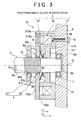
- FIG. 3 is a view of the electromagnetic clutch in a driven state
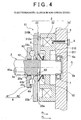
- FIG. 4 is a view of the electromagnetic clutch in a non-driven state.
- members that are the same as or equivalent to members in FIGS. 1 and 2 will be denoted by the same reference characters, and detailed descriptions of those members will be omitted.
- a relative rotation restricting device 62 of an electromagnetic clutch 61 is characterized in that relative rotation between the armature 33 and the control cam 41 is restricted by spline engagement.
- the relative rotation restricting device 62 has a pair of straight spline engaging portions 63 and 64 that are able to engage with each other, and are interposed between the armature 33 and the rotating member 2.
- the relative rotation restricting device 62 is configured to restrict relative rotation between the armature 33 and the control cam 41 by having the pair of straight spline engaging portions 63 and 64 spline engage together in response to receiving the spring force of the return spring 10.
- One straight spline engaging portion 63 is provided on the inner peripheral surface of the armature 33, and the other straight spline engaging portion 64 is provided on the outer peripheral surface of the rotating member 2.
- the axial lengths of the straight spline engaging portions 63 and 64 are set to a dimension such that the spline engagement thereof is cancelled by movement of the armature 33 in response to the electromagnetic coil 32 being energized. Therefore, when the electromagnetic coil 32 is energized, the armature 33 moves from the initial position toward the electromagnetic coil 32 side against the spring force of the return spring 10, such that spline engagement of the straight spline engaging portions 63 and 64 is cancelled. On the other hand, when the electromagnetic coil 32 is de-energized, the armature 33 moves to the initial position by the spring force of the return spring 10, such that the straight spline engaging portions 63 and 64 spline engage together.
- the spring force of the return spring 10 causes the armature 33 to press the control cam 41 against the snap ring 12 in the initial position away from the electromagnetic coil 32, and the straight spline engaging portions 63 and 64 spline engage together.
- the electromagnetic clutch functions as a brake device that brakes the rotating member 2, but the invention is not limited to this. That is, the electromagnetic clutch may also function as a driving force transmitting device that transmits driving torque between a pair of rotating members.
- An electromagnetic clutch (1) includes a rotating member (2); an electromagnetic coil (32) that is arranged on a rotational axis (O) of the rotating member (2) and generates electro-magnetic force; an output mechanism (3) that has an armature (33) to which return force in a direction away from the electromagnetic coil (32) is applied by a return spring (10); a cam mechanism (4) that is juxtaposed along the rotational axis (O) to the output mechanism (3), and has a control cam (41) that is unable to rotate relative to the rotating member (2), and a cam follower (42) that is able to roll between the control cam (41) and the armature (33); and a relative rotation restricting device (5) that is arranged on an axis of the cam mechanism (4), and that is configured to restrict relative rotation between
Landscapes
- Engineering & Computer Science (AREA)
- General Engineering & Computer Science (AREA)
- Physics & Mathematics (AREA)
- Electromagnetism (AREA)
- Mechanical Engineering (AREA)
- Braking Arrangements (AREA)
- Mechanical Operated Clutches (AREA)
Abstract
Description
- The invention relates to an electromagnetic clutch for controlling the transmission of torque between rotating members or the braking of a rotating member.
- Japanese Patent Application Publication No.
2004-17807 JP-A-2004-17807 - The output mechanism of the electromagnetic clutch has an electromagnetic coil that generates electro-magnetic force, and an armature that moves in response to the electromagnetic coil being energized. This output mechanism is arranged on a periphery of an output shaft.
- The electromagnetic coil is housed in a coil housing that rotates together with the output shaft, and is fixed to the vehicle body side.
- The armature is arranged in a position facing the electromagnetic coil via a bottom portion of the coil housing. Also, the armature is configured to friction engage with the coil housing in response to output from the output mechanism. Also, the armature is arranged so as to move away from the coil housing by the spring force of a return spring when the output mechanism stops outputting moving force.
- The cam mechanism has a gear that rotates by the driving of the electric motor, and a cam follower interposed between the gear and the armature, and is arranged on the axis of the output mechanism.
- The gear is arranged so as to be able to rotate around the periphery of the output shaft, and is coupled to an input shaft (i.e., a motor shaft of the electric motor) via a speed reducing gear train.
- The cam follower is formed by a spherical member, and is rollably arranged between the gear (i.e., a cam groove therein) and the armature (i.e., a cam groove therein).
- According to the structure described above, when the electromagnetic coil is in an energized state when the electric motor is being driven, the armature moves to the electromagnetic coil side and friction engages with the coil housing. Consequently, the cam mechanism operates. Therefore, the cam action from operation of the cam mechanism causes the armature to friction engage more strongly than before the cam mechanism is operated, such that the driving torque of the electric motor is transmitted via the cam mechanism and the like to the output shaft (i.e., to the differential side).
- On the other hand, when the electromagnetic coil is in a de-energized state (i.e., not energized) when the electric motor is stopped, the cam mechanism does not operate, so friction engagement between the armature and the coil housing is canceled by the spring force of the return spring. As a result, the transmission of driving torque from the electric motor to the differential side is interrupted.
- In the electromagnetic coil described in
JP-A-2004-17807 - In view of this problem, the invention provides an electromagnetic clutch capable of suppressing erroneous operation of a cam mechanism due to sudden acceleration thereof when the electromagnetic coil is not energized.
- A first aspect of the invention relates to an electromagnetic clutch that includes a rotating member; an electromagnetic coil that is arranged on a rotational axis of the rotating member and generates electro-magnetic force; an output mechanism that has an armature to which return force in a direction away from the electromagnetic coil is applied by a return spring; and a cam mechanism that is juxtaposed along the rotational axis to the output mechanism, and that has a cam member that is unable to rotate relative to the rotating member, and a cam follower that is able to roll between the cam member and the armature. This electromagnetic clutch is characterized by also including a relative rotation restricting device that is arranged on an axis of the cam mechanism, and that is configured to restrict relative rotation between the armature and the cam member when the electromagnetic coil is in a de-energized state.
- Also, in this electromagnetic clutch, the armature and the cam member may each have a cam groove formed by a concave groove with a depth in an axial direction that changes along a circumferential direction.
- Also, in the electromagnetic clutch described above, the relative rotation restricting device may include a retainer that is interposed between the armature and the cam member, and that rollably retains the cam follower, and may restrict the relative rotation by the retainer friction engaging with the armature and the cam member in response to receiving spring force of the return spring.
- Also, in the electromagnetic clutch described above, the retainer may have a thickness that is set to a dimension that is the same as an axial dimension between the armature and the cam member when the electromagnetic coil is in a de-energized state. Still further, the retainer may have a thickness that is set to a dimension that is larger than an axial dimension between the armature and the cam member when the electromagnetic coil is in a de-energized state.
- Also, in the electromagnetic clutch described above, the relative rotation restricting device may include a pair of spline engaging portions that are interposed between the armature and the rotating member and that are able to engage together, and may restrict the relative rotation by the armature spline engaging the pair of spline engaging portions together in response to receiving spring force of the return spring.
- Further, in the electromagnetic clutch described above, the pair of spline engaging portions may have an axial length that is set to a dimension in which a spline engaged state is cancelled by the armature moving in response to the electromagnetic coil being energized.
- Also, in the electromagnetic clutch described above, one spline engaging portion of the pair of spline engaging portions may be provided on an inner peripheral surface of the armature, and the other spline engaging portion may be provided on an outer peripheral surface of the rotating member.
- According to the invention, friction engagement of the armature is able to be suppressed by suppressing erroneous operation of the cam mechanism when the electromagnetic coil is not energized.
- The features, advantages, and technical and industrial significance of this invention will be described in the following detailed description of example embodiments of the invention with reference to the accompanying drawings, in which like numerals denote like elements, and wherein:
-
FIG. 1 is a sectional view of an electromagnetic clutch according to a first example embodiment of the invention, in a driven state; -
FIG 2 is a sectional view of the electromagnetic clutch according to the first example embodiment of the invention, in a non-driven state; -
FIG 3 is a sectional view of an electromagnetic clutch according to a second example embodiment of the invention, in a driven state; and -
FIG. 4 is a sectional view of the electromagnetic clutch according to the second example embodiment of the invention, in a non-driven state. - An electromagnetic clutch according to a first example embodiment of the invention will hereinafter be described in detail with reference to the accompanying drawings.
-
FIG. 1 is a view of the electromagnetic clutch in a driven state, andFIG. 2 is a view of the electromagnetic clutch in a non-driven state. As shown inFIGS. 1 and2 , the electromagnetic clutch 1 basically includes a rotatingmember 2 that rotates together with an input shaft, not shown, anoutput mechanism 3 that is arranged on a rotational axis O of this rotatingmember 2, acam mechanism 4 that converts the rotating force from the rotatingmember 2 into thrust in the direction of the rotational axis O by operating in response to output from thisoutput mechanism 3, and a relativerotation restricting device 5 that is arranged on the axis of thiscam mechanism 4. - The electromagnetic clutch 1 functions as a brake device for braking the rotating
member 2 with respect to acasing 6 that serves as a non-rotating member, and is used at times such as when switching a torque transmission path according to a planetary gear set, not shown, for example. Ashaft hole 6a is provided in thecasing 6, and is open on an inner surface of thecasing 6. - The rotating
member 2 is formed by a solid round shaft that has two body portions, i.e., alarge body portion 2a and asmall body portion 2b, that have different outside diameters. This rotatingmember 2 is coupled to a motor shaft (i.e., an input shaft) of an electric motor, not shown, via a reduction gear mechanism, also not shown, and is rotatably supported in theshaft hole 6a (only one is shown) of thecasing 6 via abearing 7. - The rotating
member 2 is configured to rotate together with the input shaft by the driving of the electric motor. - The large
diameter body portion 2a has a straightspline engaging portion 20a and is arranged on one side (i.e., the electric motor side) of the rotatingmember 2. The smalldiameter body portion 2b is arranged on the other side (i.e., thecasing 6 side) of the rotatingmember 2, and is integrally connected to the largediameter body portion 2a. - The
output mechanism 3 has acoil housing 31 that doubles as a coil holder, anelectromagnetic coil 32 that generates electro-magnetic force within thiscoil housing 31, and anarmature 33 that moves in response to theelectromagnetic coil 32 being energized. Thisoutput mechanism 3 is arranged around the periphery of the rotatingmember 2. - Also, the
output mechanism 3 is configured to output moving force to thearmature 33 by generating electro-magnetic force that becomes pushing force P1 with respect to thecoil housing 31, with theelectromagnetic coil 32. - The
coil housing 31 is formed by an annular member that has acoil holder 310 that serves as a yolk, and aninner flange 311, and that is fixed to thecasing 6 by a fasteningbolt 8. The rotatingmember 2 extends completely through thecoil housing 31. - The
coil holder 310 has an annularcoil housing portion 310a that opens on thearmature 33 side, and is arranged on the outer peripheral side of thecoil housing 31. Afriction surface 310b that is directed toward the end surface on thecoil housing 31 side of thearmature 33 is provided on thecoil holder 310. - The
inner flange 311 is arranged on the inner peripheral side of thecoil housing 31, and is integrally formed with the inner peripheral surface of thecoil holder 310. - The
electromagnetic coil 32 is housed, facing thearmature 33, in thecoil housing portion 310a of thecoil housing 31, and is retained by asnap ring 9. Also, theelectromagnetic coil 32 is configured to create a magnetic circuit M that straddles thearmature 33 and thecoil housing 31 and the like by being energized. - The
armature 33 is formed by an annular member that has afriction surface 33a that faces thefriction surface 310b of thecoil housing 31, and afriction surface 33b that is directed toward the relativerotation restricting device 5 side. Thisarmature 33 is arranged relatively rotatable, and relatively movable, around the periphery of the rotatingmember 2 on thecam mechanism 4 side of theoutput mechanism 3. The rotatingmember 2 extends completely through thearmature 33. - Also, the
armature 33 is configured such that thefriction surface 33a friction engages at a pressure P1 with thefriction surface 310b of thecoil housing 31, when thearmature 33 moves in the axial direction in response to output from theoutput mechanism 3. - Also, the
armature 33 has acam groove 33c that is open on an end surface that is on the opposite side of theoutput mechanism 3 from the coil housing side end surface. Thearmature 33 functions as a constituent element of thecam mechanism 4 together with a control cam (also referred to as a cam member) 41 and acam follower 42 that are constituent elements of thecam mechanism 4 that will be described later, such that thefriction surface 33a friction engages at a pressure P2 (P1 < P2) that is greater than the pressure P1 with thefriction surface 310b of thecoil housing 31 by the cam action from operation of thecam mechanism 4. Thecam groove 33c is formed by a concave groove with a depth in the axial direction that changes along the circumferential direction of thearmature 33. - Return force in a direction away from the
electromagnetic coil 32 is constantly applied to thearmature 33 by areturn spring 10. Thisreturn spring 10 is formed by a diaphragm spring, for example, and is arranged around the periphery of the rotatingmember 2, interposed between thearmature 33 and abearing 11 on the coil housing 31 (i.e., the inner flange 311). - The
cam mechanism 4 includes thecontrol cam 41 that serves as a cam member, and thecam follower 42 that is interposed between thiscontrol cam 41 and thearmature 33. Thiscam mechanism 4 is arranged around the periphery of the rotatingmember 2. - The
control cam 41 has a straightspline engaging portion 41a corresponding to the straightspline engaging portion 20a of the rotatingmember 2, and is arranged around the periphery of the largediameter body portion 2a of the rotatingmember 2 on the electric motor side of thecam mechanism 4, in a non-rotatable yet movable manner with respect to the rotatingmember 2. Thecontrol cam 41 is restricted from moving in the axial direction (toward the electric motor side) by asnap ring 12. - A
friction surface 41b that is directed toward the relativerotation restricting device 5 side, and acam groove 41c that opens on thisfriction surface 41b, are provided on thecontrol cam 41. Thecam groove 41c is formed by a concave groove with a depth in the axial direction that changes along the circumferential direction of thecontrol cam 41. - The
cam follower 42 is formed by a spherical member, and is rollably arranged between thecam groove 41c of thecontrol cam 41, and thecam groove 33c of thearmature 33. - The relative
rotation restricting device 5 includes thereturn spring 10, thesnap ring 12, and aretainer 13, and is arranged on the axis of thecam mechanism 4. - The
retainer 13 has afirst friction surface 13a facing thefriction surface 41b of thecontrol cam 41, and asecond friction surface 13b that faces thefriction surface 33b of thearmature 33. Theretainer 13 is arranged around the periphery of the rotatingmember 2, interposed between thecontrol cam 41 and thearmature 33. - Also, the
retainer 13 is configured to restrict relative rotation between thecontrol cam 41 and thearmature 33 by having the retainer thickness be set to the same dimension t as the axial dimension between thecontrol cam 41 and thearmature 33 when spring force of thereturn spring 10 is received when theelectromagnetic coil 32 is in a de-energized state, such that thefirst friction surface 13a friction engages with thefriction surface 41b of thecontrol cam 41, and thesecond friction surface 13b friction engages with thefriction surface 33b of thearmature 33. - Also, the thickness of the
retainer 13 may also be set to a dimension greater than the axial dimension between thecontrol cam 41 and thearmature 33. In this case, it is more difficult for force to be generated in the axial direction by thecam follower 42, so relative rotation between thecontrol cam 41 and thearmature 33 when thecam mechanism 4 is de-energized is able to be even more effectively restricted. - A
ball retaining hole 13c that rollably retains thecam follower 42 is provided in theretainer 13. - Next, the operation of the electromagnetic clutch 1 according to this example embodiment will be described with reference to
FIGS. 1 and2 . - In
FIG. 2 , when the electric motor, not shown, is driven, the rotational driving force of the electric motor is transmitted to the rotatingmember 2 via a reduction gear mechanism, not shown, such that the rotatingmember 2 is rotatably driven. - Normally, when starting the electric motor, the
electromagnetic coil 32 of theoutput mechanism 3 is in a de-energized state, so the magnetic circuit M that starts with theelectromagnetic coil 32 is not created, and thus thearmature 33 is not pulled toward theelectromagnetic coil 32 side via thecoil housing 31. - Therefore, in the
output mechanism 3, the pressure P1 that becomes the clutch force thereof is not generated, so thefriction surface 33a of thearmature 33 does not friction engage with thefriction surface 310b of thecoil holder 310, and thus braking force by the electromagnetic clutch 1 is not transmitted to the rotatingmember 2. - In this case, the
armature 33 presses theretainer 13 and thecontrol cam 41 against thesnap ring 12 in an initial position away from theelectromagnetic coil 32 by the spring force of thereturn spring 10, such that thefirst friction surface 13a of theretainer 13 friction engages with thefriction surface 41b of thecontrol cam 41, and thesecond friction surface 13b of theretainer 13 friction engages with thefriction surface 33b of thearmature 33. - Accordingly, in this example embodiment, relative rotation between the
armature 33 and thecontrol cam 41 is restricted when theelectromagnetic coil 32 is not energized. - Therefore, even if there is a sudden change in the rotation speed of the
control cam 41, thearmature 33 will be able to follow this sudden change in rotation speed, so relative rotation between thecontrol cam 41 and thearmature 33 will not occur. As a result, erroneous operation of thecam mechanism 4 when theelectromagnetic coil 32 is not energized can be suppressed. - On the other hand, when the
electromagnetic coil 32 is energized when the electric motor is driven (i.e., when the rotatingmember 2 is rotating), the magnetic circuit M that starts at theelectromagnetic coil 32 is created, so thearmature 33 moves from the initial position to thecoil holder 310 side of thecoil housing 31, i.e., to theelectromagnetic coil 32 side. - Accordingly, the
friction surface 33a of thearmature 33 friction engages at the pressure P1 with thefriction surface 310b of thecoil holder 310, and consequently, thecam mechanism 4 operates. - When the
cam mechanism 4 operates, thefriction surface 33a of thearmature 33 friction engages more strongly with thefriction surface 310b of thecoil holder 310 at a pressure P2 (P1 < P2) than before thecam mechanism 4 operates, due to the cam action from the operation of thecam mechanism 4. As a result, braking force from the electromagnetic clutch 1 is transmitted to the rotatingmember 2. - The effect described below is able to be obtained by the first example embodiment described above.
- Erroneous operation of the
cam mechanism 4 due to sudden acceleration thereof when theelectromagnetic coil 32 is not energized is able to be suppressed. - Next, an electromagnetic clutch according to a second example embodiment of the invention will be described with reference to
FIGS. 3 and4 .FIG. 3 is a view of the electromagnetic clutch in a driven state, andFIG. 4 is a view of the electromagnetic clutch in a non-driven state. InFIGS. 3 and4 , members that are the same as or equivalent to members inFIGS. 1 and2 will be denoted by the same reference characters, and detailed descriptions of those members will be omitted. - As shown in
FIGS. 3 and4 , a relativerotation restricting device 62 of an electromagnetic clutch 61 according to the second example embodiment of the invention is characterized in that relative rotation between thearmature 33 and thecontrol cam 41 is restricted by spline engagement. - Therefore, the relative
rotation restricting device 62 has a pair of straightspline engaging portions armature 33 and the rotatingmember 2. The relativerotation restricting device 62 is configured to restrict relative rotation between thearmature 33 and thecontrol cam 41 by having the pair of straightspline engaging portions return spring 10. - One straight
spline engaging portion 63 is provided on the inner peripheral surface of thearmature 33, and the other straightspline engaging portion 64 is provided on the outer peripheral surface of the rotatingmember 2. - The axial lengths of the straight
spline engaging portions armature 33 in response to theelectromagnetic coil 32 being energized. Therefore, when theelectromagnetic coil 32 is energized, thearmature 33 moves from the initial position toward theelectromagnetic coil 32 side against the spring force of thereturn spring 10, such that spline engagement of the straightspline engaging portions electromagnetic coil 32 is de-energized, thearmature 33 moves to the initial position by the spring force of thereturn spring 10, such that the straightspline engaging portions - In the electromagnetic clutch 61 structured in this way, when the
electromagnetic coil 32 is de-energized, the spring force of thereturn spring 10 causes thearmature 33 to press thecontrol cam 41 against thesnap ring 12 in the initial position away from theelectromagnetic coil 32, and the straightspline engaging portions - Accordingly, in this example embodiment as well, relative rotation between the
armature 33 and thecontrol cam 41 when theelectromagnetic coil 32 is de-energized can be restricted, just as in the first example embodiment. - Therefore, even if there is a sudden change in the rotation speed of the
control cam 41, thearmature 33 will be able to follow this sudden change in rotation speed, so relative rotation between thecontrol cam 41 and thearmature 33 will not occur. As a result, erroneous operation of thecam mechanism 4 when theelectromagnetic coil 32 is not energized can be suppressed. - The same effect obtained with the first example embodiment is also able to be obtained with the second example embodiment described above.
- While the electromagnetic clutch of the invention has been described with reference to example embodiments thereof, it should be understood that the invention is not limited to these example embodiments. That is, the invention may be carried out in modes that have been modified or improved in any of a variety of ways without departing from the scope thereof. For example, the modification described below is also possible.
- In the example embodiment described above, the electromagnetic clutch functions as a brake device that brakes the rotating
member 2, but the invention is not limited to this. That is, the electromagnetic clutch may also function as a driving force transmitting device that transmits driving torque between a pair of rotating members.
An electromagnetic clutch (1) includes a rotating member (2); an electromagnetic coil (32) that is arranged on a rotational axis (O) of the rotating member (2) and generates electro-magnetic force; an output mechanism (3) that has an armature (33) to which return force in a direction away from the electromagnetic coil (32) is applied by a return spring (10); a cam mechanism (4) that is juxtaposed along the rotational axis (O) to the output mechanism (3), and has a control cam (41) that is unable to rotate relative to the rotating member (2), and a cam follower (42) that is able to roll between the control cam (41) and the armature (33); and a relative rotation restricting device (5) that is arranged on an axis of the cam mechanism (4), and that is configured to restrict relative rotation between the armature (33) and the control cam (41) when the electromagnetic coil (32) is in a de-energized state.
Claims (8)
- An electromagnetic clutch that includes a rotating member (2); an electromagnetic coil (32) that is arranged on a rotational axis of the rotating member (2) and generates electro-magnetic force; an output mechanism (3) that has an armature (33) to which return force in a direction away from the electromagnetic coil (32) is applied by a return spring (10); and a cam mechanism (4) that is juxtaposed along the rotational axis to the output mechanism (3), and that has a cam member (41) that is unable to rotate relative to the rotating member (2), and a cam follower (42) that is able to roll between the cam member (41) and the armature (33); characterized by comprising:a relative rotation restricting device (5) that is arranged on an axis of the cam mechanism (4), and that is configured to restrict relative rotation between the armature (33) and the cam member (41) when the electromagnetic coil (32) is in a de-energized state.
- The electromagnetic clutch according to claim 1, characterized in that the armature (33) and the cam member (41) each have a cam groove (33c, 41c) formed by a concave groove with a depth in an axial direction that changes along a circumferential direction.
- The electromagnetic clutch according to claim 1 or 2, characterized in that the relative rotation restricting device (5) includes a retainer (13) that is interposed between the armature (33) and the cam member (41), and that rollably retains the cam follower (42), and restricts the relative rotation by the retainer (13) friction engaging with the armature (33) and the cam member (41) in response to receiving spring force of the return spring (10).
- The electromagnetic clutch according to claim 3, characterized in that the retainer (13) has a thickness that is set to a dimension that is the same as an axial dimension between the armature (33) and the cam member (41) when the electromagnetic coil (32) is in a de-energized state.
- The electromagnetic clutch according to claim 3, characterized in that the retainer (13) has a thickness that is set to a dimension that is larger than an axial dimension between the armature (33) and the cam member (41) when the electromagnetic coil (32) is in a de-energized state.
- The electromagnetic clutch according to claim 1, characterized in that the relative rotation restricting device (62) includes a pair of spline engaging portions (63, 64) that are interposed between the armature (33) and the rotating member (2) and that are able to engage together, and restricts the relative rotation by the armature (33) spline engaging the pair of spline engaging portions (63, 64) together in response to receiving spring force of the return spring (10).
- The electromagnetic clutch according to claim 6, characterized in that the pair of spline engaging portions (63, 64) has an axial length that is set to a dimension in which a spline engaged state is cancelled by the armature (33) moving in response to the electromagnetic coil (32) being energized.
- The electromagnetic clutch according to claim 6 or 7, characterized in that one spline engaging portion (63) of the pair of spline engaging portions (63, 64) is provided on an inner peripheral surface of the armature (33), and the other spline engaging portion (64) is provided on an outer peripheral surface of the rotating member (2).
Applications Claiming Priority (1)
| Application Number | Priority Date | Filing Date | Title |
|---|---|---|---|
| JP2010245511A JP5672976B2 (en) | 2010-11-01 | 2010-11-01 | Electromagnetic clutch |
Publications (3)
| Publication Number | Publication Date |
|---|---|
| EP2447562A2 true EP2447562A2 (en) | 2012-05-02 |
| EP2447562A3 EP2447562A3 (en) | 2017-05-24 |
| EP2447562B1 EP2447562B1 (en) | 2018-08-01 |
Family
ID=44897642
Family Applications (1)
| Application Number | Title | Priority Date | Filing Date |
|---|---|---|---|
| EP11186730.5A Not-in-force EP2447562B1 (en) | 2010-11-01 | 2011-10-26 | Electromagnetic clutch |
Country Status (4)
| Country | Link |
|---|---|
| US (1) | US8714329B2 (en) |
| EP (1) | EP2447562B1 (en) |
| JP (1) | JP5672976B2 (en) |
| CN (1) | CN102454726B (en) |
Cited By (3)
| Publication number | Priority date | Publication date | Assignee | Title |
|---|---|---|---|---|
| WO2014114554A1 (en) * | 2013-01-28 | 2014-07-31 | Magna Powertrain Ag & Co Kg | Shiftable clutch of a hybrid drive |
| DE102013213144A1 (en) * | 2013-07-04 | 2015-01-08 | Magna Powertrain Ag & Co. Kg | clutch |
| CN105605121A (en) * | 2015-04-17 | 2016-05-25 | 盖茨胜地汽车水泵产品(烟台)有限责任公司 | Electromagnetic clutch |
Families Citing this family (6)
| Publication number | Priority date | Publication date | Assignee | Title |
|---|---|---|---|---|
| US8790199B2 (en) * | 2010-04-26 | 2014-07-29 | Ray Schoenfelder | Radial diaphragm spring clutch |
| JP5360259B2 (en) | 2012-04-23 | 2013-12-04 | 三菱エンジニアリングプラスチックス株式会社 | Aromatic polycarbonate composite resin composition and molded article |
| KR102564284B1 (en) * | 2015-09-03 | 2023-08-11 | 워언 오토모티브 엘엘씨 | Electromagnetic coil system and methods |
| JP6759918B2 (en) * | 2016-09-16 | 2020-09-23 | 株式会社ジェイテクト | How to manufacture the hub unit |
| CN111433477B (en) * | 2017-09-30 | 2022-01-07 | 深圳市艾莱茵科技有限公司 | Electromagnetic clutch and gearbox |
| US11920666B2 (en) * | 2022-05-31 | 2024-03-05 | Gkn Automotive Limited | Rotary power transmission device with bi-stable clutch |
Citations (1)
| Publication number | Priority date | Publication date | Assignee | Title |
|---|---|---|---|---|
| JP2004017807A (en) | 2002-06-17 | 2004-01-22 | Toyoda Mach Works Ltd | Drive |
Family Cites Families (12)
| Publication number | Priority date | Publication date | Assignee | Title |
|---|---|---|---|---|
| US2623619A (en) * | 1946-09-03 | 1952-12-30 | Clerk Robert Cecil | Friction clutch and brake |
| US3092307A (en) * | 1959-07-15 | 1963-06-04 | Gen Motors Corp | Compressor |
| US3394787A (en) * | 1967-05-31 | 1968-07-30 | Stearns Electric Corp | Self-adjusting clutch or brake |
| US4079821A (en) * | 1976-05-17 | 1978-03-21 | Facet Enterprises, Inc. | Electromagnetic clutch |
| GB2034834B (en) * | 1978-10-17 | 1982-11-10 | Powell R E | Disc brake assemblies |
| US5651437A (en) * | 1996-04-17 | 1997-07-29 | Eaton Corporation | Clutch ball ramp actuator to maintain state upon loss of power |
| US6412618B1 (en) * | 2000-06-27 | 2002-07-02 | Eaton Corporation | Ball-ramp-actuated friction clutch controlled by a particle-clutch |
| US6691845B2 (en) * | 2001-11-21 | 2004-02-17 | Borgwarner, Inc. | Ball ramp clutch having force amplifying configuration |
| JP4126986B2 (en) * | 2002-07-31 | 2008-07-30 | 株式会社ジェイテクト | Clutch device |
| DE60301837T2 (en) * | 2002-08-30 | 2006-06-29 | Toyoda Koki K.K., Kariya | Electromagnetic coupling |
| JP4905036B2 (en) * | 2006-09-29 | 2012-03-28 | 株式会社ジェイテクト | Driving force transmission device |
| JP2011122679A (en) * | 2009-12-11 | 2011-06-23 | Jtekt Corp | Electromagnetic clutch |
-
2010
- 2010-11-01 JP JP2010245511A patent/JP5672976B2/en not_active Expired - Fee Related
-
2011
- 2011-10-26 EP EP11186730.5A patent/EP2447562B1/en not_active Not-in-force
- 2011-10-31 CN CN201110349764.8A patent/CN102454726B/en not_active Expired - Fee Related
- 2011-10-31 US US13/285,671 patent/US8714329B2/en not_active Expired - Fee Related
Patent Citations (1)
| Publication number | Priority date | Publication date | Assignee | Title |
|---|---|---|---|---|
| JP2004017807A (en) | 2002-06-17 | 2004-01-22 | Toyoda Mach Works Ltd | Drive |
Cited By (6)
| Publication number | Priority date | Publication date | Assignee | Title |
|---|---|---|---|---|
| WO2014114554A1 (en) * | 2013-01-28 | 2014-07-31 | Magna Powertrain Ag & Co Kg | Shiftable clutch of a hybrid drive |
| US9829052B2 (en) | 2013-01-28 | 2017-11-28 | Magna Powertrain Ag & Co Kg | Shiftable clutch of a hybrid drive |
| DE102013213144A1 (en) * | 2013-07-04 | 2015-01-08 | Magna Powertrain Ag & Co. Kg | clutch |
| DE102013213144B4 (en) * | 2013-07-04 | 2015-07-16 | Magna Powertrain Ag & Co. Kg | clutch |
| CN105605121A (en) * | 2015-04-17 | 2016-05-25 | 盖茨胜地汽车水泵产品(烟台)有限责任公司 | Electromagnetic clutch |
| CN105605121B (en) * | 2015-04-17 | 2017-11-24 | 盖茨胜地汽车水泵产品(烟台)有限责任公司 | Electromagnetic clutch |
Also Published As
| Publication number | Publication date |
|---|---|
| JP5672976B2 (en) | 2015-02-18 |
| EP2447562A3 (en) | 2017-05-24 |
| EP2447562B1 (en) | 2018-08-01 |
| CN102454726B (en) | 2016-05-11 |
| CN102454726A (en) | 2012-05-16 |
| JP2012097805A (en) | 2012-05-24 |
| US8714329B2 (en) | 2014-05-06 |
| US20120103750A1 (en) | 2012-05-03 |
Similar Documents
| Publication | Publication Date | Title |
|---|---|---|
| EP2447562B1 (en) | Electromagnetic clutch | |
| US8454471B2 (en) | Electronic locking differential | |
| JP5951215B2 (en) | Clutch device | |
| JP2011236984A (en) | Electric direct-action actuator and electric brake device | |
| US11815171B2 (en) | Differential device | |
| JP2009156283A (en) | Rotation transmitting device | |
| JP2018021575A (en) | Electric parking brake device | |
| EP2581619A2 (en) | Electromagnetic clutch | |
| US9046173B2 (en) | Transmission driving device | |
| JP4541178B2 (en) | Rotation transmission device | |
| JP2012062937A (en) | Electromagnetic clutch, and driving force transmission device equipped therewith | |
| JP5942003B2 (en) | clutch | |
| WO2017221939A1 (en) | Electric brake apparatus | |
| JP4606921B2 (en) | Rotation transmission device | |
| JP2009197958A (en) | Electric brake | |
| JP2007270983A (en) | Rotation transmission device for steer-by-wire system | |
| JP2006226366A (en) | Rotation transmission device | |
| JP2018080776A (en) | Electric actuator | |
| JP2006349109A (en) | Rotation transmitting device | |
| JP6468773B2 (en) | Rotation transmission device | |
| JP2012255519A (en) | Clutch | |
| JP2014137068A (en) | Interrupter, power transmission device using the interrupter, and vehicle drive unit using the power transmission device | |
| JP2019100527A (en) | Brake device | |
| JP2006349128A (en) | Rotation transmitting device | |
| JP2011007231A (en) | Power transmission device |
Legal Events
| Date | Code | Title | Description |
|---|---|---|---|
| PUAI | Public reference made under article 153(3) epc to a published international application that has entered the european phase |
Free format text: ORIGINAL CODE: 0009012 |
|
| AK | Designated contracting states |
Kind code of ref document: A2 Designated state(s): AL AT BE BG CH CY CZ DE DK EE ES FI FR GB GR HR HU IE IS IT LI LT LU LV MC MK MT NL NO PL PT RO RS SE SI SK SM TR |
|
| AX | Request for extension of the european patent |
Extension state: BA ME |
|
| PUAL | Search report despatched |
Free format text: ORIGINAL CODE: 0009013 |
|
| AK | Designated contracting states |
Kind code of ref document: A3 Designated state(s): AL AT BE BG CH CY CZ DE DK EE ES FI FR GB GR HR HU IE IS IT LI LT LU LV MC MK MT NL NO PL PT RO RS SE SI SK SM TR |
|
| AX | Request for extension of the european patent |
Extension state: BA ME |
|
| RIC1 | Information provided on ipc code assigned before grant |
Ipc: F16D 27/06 20060101AFI20170418BHEP |
|
| STAA | Information on the status of an ep patent application or granted ep patent |
Free format text: STATUS: REQUEST FOR EXAMINATION WAS MADE |
|
| 17P | Request for examination filed |
Effective date: 20170803 |
|
| RBV | Designated contracting states (corrected) |
Designated state(s): AL AT BE BG CH CY CZ DE DK EE ES FI FR GB GR HR HU IE IS IT LI LT LU LV MC MK MT NL NO PL PT RO RS SE SI SK SM TR |
|
| GRAP | Despatch of communication of intention to grant a patent |
Free format text: ORIGINAL CODE: EPIDOSNIGR1 |
|
| STAA | Information on the status of an ep patent application or granted ep patent |
Free format text: STATUS: GRANT OF PATENT IS INTENDED |
|
| INTG | Intention to grant announced |
Effective date: 20180207 |
|
| GRAS | Grant fee paid |
Free format text: ORIGINAL CODE: EPIDOSNIGR3 |
|
| GRAA | (expected) grant |
Free format text: ORIGINAL CODE: 0009210 |
|
| STAA | Information on the status of an ep patent application or granted ep patent |
Free format text: STATUS: THE PATENT HAS BEEN GRANTED |
|
| RIN1 | Information on inventor provided before grant (corrected) |
Inventor name: HASHIMOTO, HIROTO Inventor name: ONITAKE, MINORU Inventor name: KITABATAKE, HIROTATSU Inventor name: EBUCHI, HIROAKI Inventor name: SAKAMOTO, YOICHI Inventor name: TAKUNO, HIROSHI Inventor name: HOSOKAWA, TAKASHI Inventor name: KOMADA, HIDEAKI Inventor name: KORENAGA, KENJI |
|
| AK | Designated contracting states |
Kind code of ref document: B1 Designated state(s): AL AT BE BG CH CY CZ DE DK EE ES FI FR GB GR HR HU IE IS IT LI LT LU LV MC MK MT NL NO PL PT RO RS SE SI SK SM TR |
|
| REG | Reference to a national code |
Ref country code: GB Ref legal event code: FG4D |
|
| REG | Reference to a national code |
Ref country code: CH Ref legal event code: EP Ref country code: AT Ref legal event code: REF Ref document number: 1024659 Country of ref document: AT Kind code of ref document: T Effective date: 20180815 |
|
| REG | Reference to a national code |
Ref country code: IE Ref legal event code: FG4D |
|
| REG | Reference to a national code |
Ref country code: DE Ref legal event code: R096 Ref document number: 602011050517 Country of ref document: DE |
|
| REG | Reference to a national code |
Ref country code: NL Ref legal event code: MP Effective date: 20180801 |
|
| REG | Reference to a national code |
Ref country code: LT Ref legal event code: MG4D |
|
| REG | Reference to a national code |
Ref country code: AT Ref legal event code: MK05 Ref document number: 1024659 Country of ref document: AT Kind code of ref document: T Effective date: 20180801 |
|
| PG25 | Lapsed in a contracting state [announced via postgrant information from national office to epo] |
Ref country code: FI Free format text: LAPSE BECAUSE OF FAILURE TO SUBMIT A TRANSLATION OF THE DESCRIPTION OR TO PAY THE FEE WITHIN THE PRESCRIBED TIME-LIMIT Effective date: 20180801 Ref country code: RS Free format text: LAPSE BECAUSE OF FAILURE TO SUBMIT A TRANSLATION OF THE DESCRIPTION OR TO PAY THE FEE WITHIN THE PRESCRIBED TIME-LIMIT Effective date: 20180801 Ref country code: IS Free format text: LAPSE BECAUSE OF FAILURE TO SUBMIT A TRANSLATION OF THE DESCRIPTION OR TO PAY THE FEE WITHIN THE PRESCRIBED TIME-LIMIT Effective date: 20181201 Ref country code: AT Free format text: LAPSE BECAUSE OF FAILURE TO SUBMIT A TRANSLATION OF THE DESCRIPTION OR TO PAY THE FEE WITHIN THE PRESCRIBED TIME-LIMIT Effective date: 20180801 Ref country code: NO Free format text: LAPSE BECAUSE OF FAILURE TO SUBMIT A TRANSLATION OF THE DESCRIPTION OR TO PAY THE FEE WITHIN THE PRESCRIBED TIME-LIMIT Effective date: 20181101 Ref country code: GR Free format text: LAPSE BECAUSE OF FAILURE TO SUBMIT A TRANSLATION OF THE DESCRIPTION OR TO PAY THE FEE WITHIN THE PRESCRIBED TIME-LIMIT Effective date: 20181102 Ref country code: BG Free format text: LAPSE BECAUSE OF FAILURE TO SUBMIT A TRANSLATION OF THE DESCRIPTION OR TO PAY THE FEE WITHIN THE PRESCRIBED TIME-LIMIT Effective date: 20181101 Ref country code: SE Free format text: LAPSE BECAUSE OF FAILURE TO SUBMIT A TRANSLATION OF THE DESCRIPTION OR TO PAY THE FEE WITHIN THE PRESCRIBED TIME-LIMIT Effective date: 20180801 Ref country code: NL Free format text: LAPSE BECAUSE OF FAILURE TO SUBMIT A TRANSLATION OF THE DESCRIPTION OR TO PAY THE FEE WITHIN THE PRESCRIBED TIME-LIMIT Effective date: 20180801 Ref country code: LT Free format text: LAPSE BECAUSE OF FAILURE TO SUBMIT A TRANSLATION OF THE DESCRIPTION OR TO PAY THE FEE WITHIN THE PRESCRIBED TIME-LIMIT Effective date: 20180801 Ref country code: PL Free format text: LAPSE BECAUSE OF FAILURE TO SUBMIT A TRANSLATION OF THE DESCRIPTION OR TO PAY THE FEE WITHIN THE PRESCRIBED TIME-LIMIT Effective date: 20180801 |
|
| PG25 | Lapsed in a contracting state [announced via postgrant information from national office to epo] |
Ref country code: AL Free format text: LAPSE BECAUSE OF FAILURE TO SUBMIT A TRANSLATION OF THE DESCRIPTION OR TO PAY THE FEE WITHIN THE PRESCRIBED TIME-LIMIT Effective date: 20180801 Ref country code: LV Free format text: LAPSE BECAUSE OF FAILURE TO SUBMIT A TRANSLATION OF THE DESCRIPTION OR TO PAY THE FEE WITHIN THE PRESCRIBED TIME-LIMIT Effective date: 20180801 Ref country code: HR Free format text: LAPSE BECAUSE OF FAILURE TO SUBMIT A TRANSLATION OF THE DESCRIPTION OR TO PAY THE FEE WITHIN THE PRESCRIBED TIME-LIMIT Effective date: 20180801 Ref country code: ES Free format text: LAPSE BECAUSE OF FAILURE TO SUBMIT A TRANSLATION OF THE DESCRIPTION OR TO PAY THE FEE WITHIN THE PRESCRIBED TIME-LIMIT Effective date: 20180801 |
|
| PG25 | Lapsed in a contracting state [announced via postgrant information from national office to epo] |
Ref country code: CZ Free format text: LAPSE BECAUSE OF FAILURE TO SUBMIT A TRANSLATION OF THE DESCRIPTION OR TO PAY THE FEE WITHIN THE PRESCRIBED TIME-LIMIT Effective date: 20180801 Ref country code: IT Free format text: LAPSE BECAUSE OF FAILURE TO SUBMIT A TRANSLATION OF THE DESCRIPTION OR TO PAY THE FEE WITHIN THE PRESCRIBED TIME-LIMIT Effective date: 20180801 Ref country code: RO Free format text: LAPSE BECAUSE OF FAILURE TO SUBMIT A TRANSLATION OF THE DESCRIPTION OR TO PAY THE FEE WITHIN THE PRESCRIBED TIME-LIMIT Effective date: 20180801 Ref country code: EE Free format text: LAPSE BECAUSE OF FAILURE TO SUBMIT A TRANSLATION OF THE DESCRIPTION OR TO PAY THE FEE WITHIN THE PRESCRIBED TIME-LIMIT Effective date: 20180801 |
|
| REG | Reference to a national code |
Ref country code: DE Ref legal event code: R097 Ref document number: 602011050517 Country of ref document: DE |
|
| PG25 | Lapsed in a contracting state [announced via postgrant information from national office to epo] |
Ref country code: DK Free format text: LAPSE BECAUSE OF FAILURE TO SUBMIT A TRANSLATION OF THE DESCRIPTION OR TO PAY THE FEE WITHIN THE PRESCRIBED TIME-LIMIT Effective date: 20180801 Ref country code: SM Free format text: LAPSE BECAUSE OF FAILURE TO SUBMIT A TRANSLATION OF THE DESCRIPTION OR TO PAY THE FEE WITHIN THE PRESCRIBED TIME-LIMIT Effective date: 20180801 Ref country code: SK Free format text: LAPSE BECAUSE OF FAILURE TO SUBMIT A TRANSLATION OF THE DESCRIPTION OR TO PAY THE FEE WITHIN THE PRESCRIBED TIME-LIMIT Effective date: 20180801 |
|
| REG | Reference to a national code |
Ref country code: CH Ref legal event code: PL |
|
| PLBE | No opposition filed within time limit |
Free format text: ORIGINAL CODE: 0009261 |
|
| STAA | Information on the status of an ep patent application or granted ep patent |
Free format text: STATUS: NO OPPOSITION FILED WITHIN TIME LIMIT |
|
| REG | Reference to a national code |
Ref country code: BE Ref legal event code: MM Effective date: 20181031 |
|
| PG25 | Lapsed in a contracting state [announced via postgrant information from national office to epo] |
Ref country code: LU Free format text: LAPSE BECAUSE OF NON-PAYMENT OF DUE FEES Effective date: 20181026 Ref country code: MC Free format text: LAPSE BECAUSE OF FAILURE TO SUBMIT A TRANSLATION OF THE DESCRIPTION OR TO PAY THE FEE WITHIN THE PRESCRIBED TIME-LIMIT Effective date: 20180801 |
|
| 26N | No opposition filed |
Effective date: 20190503 |
|
| GBPC | Gb: european patent ceased through non-payment of renewal fee |
Effective date: 20181101 |
|
| REG | Reference to a national code |
Ref country code: IE Ref legal event code: MM4A |
|
| PG25 | Lapsed in a contracting state [announced via postgrant information from national office to epo] |
Ref country code: CH Free format text: LAPSE BECAUSE OF NON-PAYMENT OF DUE FEES Effective date: 20181031 Ref country code: BE Free format text: LAPSE BECAUSE OF NON-PAYMENT OF DUE FEES Effective date: 20181031 Ref country code: FR Free format text: LAPSE BECAUSE OF NON-PAYMENT OF DUE FEES Effective date: 20181031 Ref country code: LI Free format text: LAPSE BECAUSE OF NON-PAYMENT OF DUE FEES Effective date: 20181031 Ref country code: SI Free format text: LAPSE BECAUSE OF FAILURE TO SUBMIT A TRANSLATION OF THE DESCRIPTION OR TO PAY THE FEE WITHIN THE PRESCRIBED TIME-LIMIT Effective date: 20180801 |
|
| PG25 | Lapsed in a contracting state [announced via postgrant information from national office to epo] |
Ref country code: IE Free format text: LAPSE BECAUSE OF NON-PAYMENT OF DUE FEES Effective date: 20181026 |
|
| PG25 | Lapsed in a contracting state [announced via postgrant information from national office to epo] |
Ref country code: GB Free format text: LAPSE BECAUSE OF NON-PAYMENT OF DUE FEES Effective date: 20181101 |
|
| PG25 | Lapsed in a contracting state [announced via postgrant information from national office to epo] |
Ref country code: MT Free format text: LAPSE BECAUSE OF NON-PAYMENT OF DUE FEES Effective date: 20181026 |
|
| PG25 | Lapsed in a contracting state [announced via postgrant information from national office to epo] |
Ref country code: TR Free format text: LAPSE BECAUSE OF FAILURE TO SUBMIT A TRANSLATION OF THE DESCRIPTION OR TO PAY THE FEE WITHIN THE PRESCRIBED TIME-LIMIT Effective date: 20180801 |
|
| PG25 | Lapsed in a contracting state [announced via postgrant information from national office to epo] |
Ref country code: PT Free format text: LAPSE BECAUSE OF FAILURE TO SUBMIT A TRANSLATION OF THE DESCRIPTION OR TO PAY THE FEE WITHIN THE PRESCRIBED TIME-LIMIT Effective date: 20180801 |
|
| PG25 | Lapsed in a contracting state [announced via postgrant information from national office to epo] |
Ref country code: MK Free format text: LAPSE BECAUSE OF NON-PAYMENT OF DUE FEES Effective date: 20180801 Ref country code: HU Free format text: LAPSE BECAUSE OF FAILURE TO SUBMIT A TRANSLATION OF THE DESCRIPTION OR TO PAY THE FEE WITHIN THE PRESCRIBED TIME-LIMIT; INVALID AB INITIO Effective date: 20111026 Ref country code: CY Free format text: LAPSE BECAUSE OF FAILURE TO SUBMIT A TRANSLATION OF THE DESCRIPTION OR TO PAY THE FEE WITHIN THE PRESCRIBED TIME-LIMIT Effective date: 20180801 |
|
| PGFP | Annual fee paid to national office [announced via postgrant information from national office to epo] |
Ref country code: DE Payment date: 20201013 Year of fee payment: 10 |
|
| REG | Reference to a national code |
Ref country code: DE Ref legal event code: R119 Ref document number: 602011050517 Country of ref document: DE |
|
| PG25 | Lapsed in a contracting state [announced via postgrant information from national office to epo] |
Ref country code: DE Free format text: LAPSE BECAUSE OF NON-PAYMENT OF DUE FEES Effective date: 20220503 |