EP2447100A1 - Hybrid vehicle - Google Patents
Hybrid vehicle Download PDFInfo
- Publication number
- EP2447100A1 EP2447100A1 EP10791774A EP10791774A EP2447100A1 EP 2447100 A1 EP2447100 A1 EP 2447100A1 EP 10791774 A EP10791774 A EP 10791774A EP 10791774 A EP10791774 A EP 10791774A EP 2447100 A1 EP2447100 A1 EP 2447100A1
- Authority
- EP
- European Patent Office
- Prior art keywords
- vehicle
- battery
- floor panel
- seat
- housing space
- Prior art date
- Legal status (The legal status is an assumption and is not a legal conclusion. Google has not performed a legal analysis and makes no representation as to the accuracy of the status listed.)
- Granted
Links
Images


Classifications
-
- B—PERFORMING OPERATIONS; TRANSPORTING
- B62—LAND VEHICLES FOR TRAVELLING OTHERWISE THAN ON RAILS
- B62D—MOTOR VEHICLES; TRAILERS
- B62D25/00—Superstructure or monocoque structure sub-units; Parts or details thereof not otherwise provided for
- B62D25/20—Floors or bottom sub-units
-
- B—PERFORMING OPERATIONS; TRANSPORTING
- B60—VEHICLES IN GENERAL
- B60K—ARRANGEMENT OR MOUNTING OF PROPULSION UNITS OR OF TRANSMISSIONS IN VEHICLES; ARRANGEMENT OR MOUNTING OF PLURAL DIVERSE PRIME-MOVERS IN VEHICLES; AUXILIARY DRIVES FOR VEHICLES; INSTRUMENTATION OR DASHBOARDS FOR VEHICLES; ARRANGEMENTS IN CONNECTION WITH COOLING, AIR INTAKE, GAS EXHAUST OR FUEL SUPPLY OF PROPULSION UNITS IN VEHICLES
- B60K1/00—Arrangement or mounting of electrical propulsion units
- B60K1/04—Arrangement or mounting of electrical propulsion units of the electric storage means for propulsion
-
- B—PERFORMING OPERATIONS; TRANSPORTING
- B60—VEHICLES IN GENERAL
- B60L—PROPULSION OF ELECTRICALLY-PROPELLED VEHICLES; SUPPLYING ELECTRIC POWER FOR AUXILIARY EQUIPMENT OF ELECTRICALLY-PROPELLED VEHICLES; ELECTRODYNAMIC BRAKE SYSTEMS FOR VEHICLES IN GENERAL; MAGNETIC SUSPENSION OR LEVITATION FOR VEHICLES; MONITORING OPERATING VARIABLES OF ELECTRICALLY-PROPELLED VEHICLES; ELECTRIC SAFETY DEVICES FOR ELECTRICALLY-PROPELLED VEHICLES
- B60L1/00—Supplying electric power to auxiliary equipment of vehicles
- B60L1/003—Supplying electric power to auxiliary equipment of vehicles to auxiliary motors, e.g. for pumps, compressors
-
- B—PERFORMING OPERATIONS; TRANSPORTING
- B60—VEHICLES IN GENERAL
- B60L—PROPULSION OF ELECTRICALLY-PROPELLED VEHICLES; SUPPLYING ELECTRIC POWER FOR AUXILIARY EQUIPMENT OF ELECTRICALLY-PROPELLED VEHICLES; ELECTRODYNAMIC BRAKE SYSTEMS FOR VEHICLES IN GENERAL; MAGNETIC SUSPENSION OR LEVITATION FOR VEHICLES; MONITORING OPERATING VARIABLES OF ELECTRICALLY-PROPELLED VEHICLES; ELECTRIC SAFETY DEVICES FOR ELECTRICALLY-PROPELLED VEHICLES
- B60L50/00—Electric propulsion with power supplied within the vehicle
- B60L50/10—Electric propulsion with power supplied within the vehicle using propulsion power supplied by engine-driven generators, e.g. generators driven by combustion engines
- B60L50/16—Electric propulsion with power supplied within the vehicle using propulsion power supplied by engine-driven generators, e.g. generators driven by combustion engines with provision for separate direct mechanical propulsion
-
- B—PERFORMING OPERATIONS; TRANSPORTING
- B60—VEHICLES IN GENERAL
- B60L—PROPULSION OF ELECTRICALLY-PROPELLED VEHICLES; SUPPLYING ELECTRIC POWER FOR AUXILIARY EQUIPMENT OF ELECTRICALLY-PROPELLED VEHICLES; ELECTRODYNAMIC BRAKE SYSTEMS FOR VEHICLES IN GENERAL; MAGNETIC SUSPENSION OR LEVITATION FOR VEHICLES; MONITORING OPERATING VARIABLES OF ELECTRICALLY-PROPELLED VEHICLES; ELECTRIC SAFETY DEVICES FOR ELECTRICALLY-PROPELLED VEHICLES
- B60L50/00—Electric propulsion with power supplied within the vehicle
- B60L50/50—Electric propulsion with power supplied within the vehicle using propulsion power supplied by batteries or fuel cells
- B60L50/60—Electric propulsion with power supplied within the vehicle using propulsion power supplied by batteries or fuel cells using power supplied by batteries
- B60L50/66—Arrangements of batteries
-
- B—PERFORMING OPERATIONS; TRANSPORTING
- B60—VEHICLES IN GENERAL
- B60L—PROPULSION OF ELECTRICALLY-PROPELLED VEHICLES; SUPPLYING ELECTRIC POWER FOR AUXILIARY EQUIPMENT OF ELECTRICALLY-PROPELLED VEHICLES; ELECTRODYNAMIC BRAKE SYSTEMS FOR VEHICLES IN GENERAL; MAGNETIC SUSPENSION OR LEVITATION FOR VEHICLES; MONITORING OPERATING VARIABLES OF ELECTRICALLY-PROPELLED VEHICLES; ELECTRIC SAFETY DEVICES FOR ELECTRICALLY-PROPELLED VEHICLES
- B60L58/00—Methods or circuit arrangements for monitoring or controlling batteries or fuel cells, specially adapted for electric vehicles
- B60L58/10—Methods or circuit arrangements for monitoring or controlling batteries or fuel cells, specially adapted for electric vehicles for monitoring or controlling batteries
- B60L58/18—Methods or circuit arrangements for monitoring or controlling batteries or fuel cells, specially adapted for electric vehicles for monitoring or controlling batteries of two or more battery modules
- B60L58/20—Methods or circuit arrangements for monitoring or controlling batteries or fuel cells, specially adapted for electric vehicles for monitoring or controlling batteries of two or more battery modules having different nominal voltages
-
- H—ELECTRICITY
- H01—ELECTRIC ELEMENTS
- H01M—PROCESSES OR MEANS, e.g. BATTERIES, FOR THE DIRECT CONVERSION OF CHEMICAL ENERGY INTO ELECTRICAL ENERGY
- H01M50/00—Constructional details or processes of manufacture of the non-active parts of electrochemical cells other than fuel cells, e.g. hybrid cells
- H01M50/20—Mountings; Secondary casings or frames; Racks, modules or packs; Suspension devices; Shock absorbers; Transport or carrying devices; Holders
- H01M50/204—Racks, modules or packs for multiple batteries or multiple cells
- H01M50/207—Racks, modules or packs for multiple batteries or multiple cells characterised by their shape
- H01M50/209—Racks, modules or packs for multiple batteries or multiple cells characterised by their shape adapted for prismatic or rectangular cells
-
- B—PERFORMING OPERATIONS; TRANSPORTING
- B60—VEHICLES IN GENERAL
- B60K—ARRANGEMENT OR MOUNTING OF PROPULSION UNITS OR OF TRANSMISSIONS IN VEHICLES; ARRANGEMENT OR MOUNTING OF PLURAL DIVERSE PRIME-MOVERS IN VEHICLES; AUXILIARY DRIVES FOR VEHICLES; INSTRUMENTATION OR DASHBOARDS FOR VEHICLES; ARRANGEMENTS IN CONNECTION WITH COOLING, AIR INTAKE, GAS EXHAUST OR FUEL SUPPLY OF PROPULSION UNITS IN VEHICLES
- B60K1/00—Arrangement or mounting of electrical propulsion units
- B60K1/04—Arrangement or mounting of electrical propulsion units of the electric storage means for propulsion
- B60K2001/0405—Arrangement or mounting of electrical propulsion units of the electric storage means for propulsion characterised by their position
- B60K2001/0433—Arrangement under the rear seats
-
- B—PERFORMING OPERATIONS; TRANSPORTING
- B60—VEHICLES IN GENERAL
- B60L—PROPULSION OF ELECTRICALLY-PROPELLED VEHICLES; SUPPLYING ELECTRIC POWER FOR AUXILIARY EQUIPMENT OF ELECTRICALLY-PROPELLED VEHICLES; ELECTRODYNAMIC BRAKE SYSTEMS FOR VEHICLES IN GENERAL; MAGNETIC SUSPENSION OR LEVITATION FOR VEHICLES; MONITORING OPERATING VARIABLES OF ELECTRICALLY-PROPELLED VEHICLES; ELECTRIC SAFETY DEVICES FOR ELECTRICALLY-PROPELLED VEHICLES
- B60L2270/00—Problem solutions or means not otherwise provided for
- B60L2270/10—Emission reduction
- B60L2270/14—Emission reduction of noise
- B60L2270/145—Structure borne vibrations
-
- Y—GENERAL TAGGING OF NEW TECHNOLOGICAL DEVELOPMENTS; GENERAL TAGGING OF CROSS-SECTIONAL TECHNOLOGIES SPANNING OVER SEVERAL SECTIONS OF THE IPC; TECHNICAL SUBJECTS COVERED BY FORMER USPC CROSS-REFERENCE ART COLLECTIONS [XRACs] AND DIGESTS
- Y02—TECHNOLOGIES OR APPLICATIONS FOR MITIGATION OR ADAPTATION AGAINST CLIMATE CHANGE
- Y02E—REDUCTION OF GREENHOUSE GAS [GHG] EMISSIONS, RELATED TO ENERGY GENERATION, TRANSMISSION OR DISTRIBUTION
- Y02E60/00—Enabling technologies; Technologies with a potential or indirect contribution to GHG emissions mitigation
- Y02E60/10—Energy storage using batteries
-
- Y—GENERAL TAGGING OF NEW TECHNOLOGICAL DEVELOPMENTS; GENERAL TAGGING OF CROSS-SECTIONAL TECHNOLOGIES SPANNING OVER SEVERAL SECTIONS OF THE IPC; TECHNICAL SUBJECTS COVERED BY FORMER USPC CROSS-REFERENCE ART COLLECTIONS [XRACs] AND DIGESTS
- Y02—TECHNOLOGIES OR APPLICATIONS FOR MITIGATION OR ADAPTATION AGAINST CLIMATE CHANGE
- Y02T—CLIMATE CHANGE MITIGATION TECHNOLOGIES RELATED TO TRANSPORTATION
- Y02T10/00—Road transport of goods or passengers
- Y02T10/60—Other road transportation technologies with climate change mitigation effect
- Y02T10/70—Energy storage systems for electromobility, e.g. batteries
-
- Y—GENERAL TAGGING OF NEW TECHNOLOGICAL DEVELOPMENTS; GENERAL TAGGING OF CROSS-SECTIONAL TECHNOLOGIES SPANNING OVER SEVERAL SECTIONS OF THE IPC; TECHNICAL SUBJECTS COVERED BY FORMER USPC CROSS-REFERENCE ART COLLECTIONS [XRACs] AND DIGESTS
- Y02—TECHNOLOGIES OR APPLICATIONS FOR MITIGATION OR ADAPTATION AGAINST CLIMATE CHANGE
- Y02T—CLIMATE CHANGE MITIGATION TECHNOLOGIES RELATED TO TRANSPORTATION
- Y02T10/00—Road transport of goods or passengers
- Y02T10/60—Other road transportation technologies with climate change mitigation effect
- Y02T10/7072—Electromobility specific charging systems or methods for batteries, ultracapacitors, supercapacitors or double-layer capacitors
Definitions
- the present invention relates to a hybrid vehicle including an engine and an electric motor, both of which are used as a power source.
- a hybrid vehicle including, as a power source, both an engine and an electric motor has mounted thereto a battery (hereinafter sometimes referred to as a "main battery") for feeding power to the electric motor.
- a battery hereinafter sometimes referred to as a "main battery"
- the main battery When the main battery is arranged in a vehicle compartment, it narrows the interior space where passengers or luggage are accommodated.
- Patent Literature 1 secures a mounting space of an electric storage device below a rear seat in order to prevent a comfort in the vehicle compartment from being deteriorated due to the electric storage device.
- the Patent Literature 1 describes that not only a battery pack 600 but also another battery pack 2600 and a junction box 800 are mounted, and the battery pack 2600 is mounted on a top surface of a rising portion 110 as a third embodiment.
- a hybrid vehicle may have mounted thereto another battery (hereinafter sometimes referred to as an "auxiliary battery") for assisting a power supply by the main battery in order to supply a voltage to accessories such as an ECU (electronic control unit) operating with a low voltage (e.g., 12 V) or in order to prepare for troubles such as low battery charge of the main battery.
- an ECU electronic control unit
- a low voltage e.g. 12 V
- the hybrid vehicle is provided with an engine and an inverter in an engine compartment at the front part of the vehicle, a sufficient space for arranging the auxiliary battery cannot be secured in the engine compartment. Therefore, the place where the auxiliary battery is mounted becomes a problem.
- the auxiliary battery is mounted on the top surface of the rising portion of a floor panel at the rear of the rear seat as described in the Patent Literature 1. In this case, an interior space at the rear of the rear seat is decreased (see paragraph 0065 in Patent Literature 1).
- the auxiliary battery is arranged in a space enclosed by a rear panel at the rear of a wheel house of a rear tire.
- the auxiliary battery might be damaged, when the rear part of the vehicle is hit.
- the arrangement of the auxiliary battery described above can be realized only in a sedan vehicle having a long rear overhang, and in a compact hatch-back vehicle having a short rear overhang, this arrangement cannot be realized without narrowing a cargo room.
- the present invention aims to mount both a battery for driving an electric motor and a preparatory auxiliary battery to a hybrid vehicle without narrowing a cargo room.
- a hybrid vehicle includes: a floor panel including a rising portion that rises upward and extends in a widthwise direction of the vehicle, and a front portion that extends in a forward direction of the vehicle from the rising portion; a fuel tank that is mounted below the floor panel, and that stores liquid fuel burned in an engine serving as a power source of the vehicle; a rear seat provided above the floor panel with a seat portion which supports a hip of a passenger being opposite to the front portion; a first mounting portion that is formed in a housing space enclosed by the front portion, the seat portion, and the rising portion, so as to mount a first battery which stores driving power of an electric motor serving as the power source of the vehicle; and a second mounting portion that is formed in the housing space as being side by side with the first mounting portion in the widthwise direction of the vehicle so as to mount a second battery which assists a power supply by the first battery.
- two batteries can be arranged side by side below a rear seat. Accordingly, both the main battery and the auxiliary battery can be mounted on the hybrid vehicle without narrowing the cargo room.
- FIG. 1 is a plan view of a vehicle 101.
- the vehicle 101 is a hybrid type including an engine and an electric motor (both are not illustrated), both of which are used as a power source.
- the vehicle 101 has an engine compartment (not illustrated) at its front part.
- the engine, the electric motor, and an inverter (not illustrated) connected to the electric motor are mounted inside the engine compartment.
- a rear seat 109 is mounted in the vehicle 101.
- the vehicle 101 has, provided below or at the rear of the rear seat 109, a floor panel 102, a left side member 103L, a right side member 103R, a center cross member 104, a first rear cross member 105, a second rear cross member 106, a left rear tire 107L, a right rear tire 107R, a suspension member 108, a main battery 110 serving as a first battery, an auxiliary battery 111 serving as a second battery, a fuel tank 112, and a rear wheel house 114.
- the floor panel 102 forms a floor surface of the interior of the vehicle 101.
- the floor panel 102 has a front portion 102a extending toward the front part of the vehicle 101 as extending substantially horizontally, and a rear portion 102b extending toward the rear of the vehicle 101.
- the floor panel 102 has a rising portion 102c between the front portion 102a and the rear portion 102b.
- the rising portion 102c projects upward from both the front portion 102a and the rear portion 102b of the floor panel 102, and forms a ridge extending in the widthwise direction of the vehicle 101.
- the first rear cross member 105 is positioned below the rising portion 102c.
- the rear seat 109 includes a seat portion 10 9a that supports a hip of a passenger, and a backrest portion 109b that supports a back of the passenger.
- the backrest portion 109b projects upward from a trailing end of the seat portion 109a.
- the rear seat 109 is positioned above the floor panel 102 with the portion of the rear part of the lower surface of the seat portion 109a being supported by the rising portion 102c.
- the seat portion 109a is parallel to the front portion 102a, and is opposite to the front portion 102a.
- a space in the vehicle 101 at the rear of the rear seat 109 is used as a cargo room 113.
- the backrest portion 109b of the rear seat 109 forms a front wall surface of the cargo room 113.
- the floor surface of the cargo room 113 is formed by the rear portion 102b and a spare tire accommodating portion cover 131.
- a spare tire accommodating portion 133 for accommodating a spare tire 132 is formed to have a shape recessed downward at the rear portion 102b of the floor panel 102.
- the spare tire accommodating portion cover 131 is positioned above the spare tire 132 accommodated in the spare tire accommodating portion 133, and it covers the spare tire accommodating portion 133 so as to form the flat floor surface of the cargo room 113.
- the rear wheel houses 114 are located at both right and left sides and at the rear part of the vehicle 101, and at both right and left sides of the cargo room 113, and they are arranged at the position at the rear of the rear seat 109.
- the rear wheel house 114 projects upward from the rear portion 102b of the floor panel 102.
- a left rear tire 107L is located below the left rear wheel house 114 so as to be rotatable.
- a right rear tire 107R is located below the right rear wheel house 114 so as to be rotatable.
- the right and left rear wheel houses 114 are covered by a rear panel (not illustrated) forming an outer appearance of the vehicle 101.
- the left side member 103L and the right side member 103R are members extending in the longitudinal direction of the vehicle 101, and they are attached to regions on right and left sides of the floor panel 102. More specifically, the left side member 103L includes a portion LA extending in the longitudinal direction of the vehicle 101 along a right side of the left rear wheel house 114, a portion LB extending around from the portion LA toward an outer direction (leftward) of the vehicle 101 along the shape of the front part of the left rear wheel house 114, and a portion LC extending from the portion LB toward the front part as making close to the outer direction of the vehicle 101.
- the right side member 103R has substantially a symmetrical shape with the left side member 103L.
- the left side member 103L and the right side member 103R extend in the longitudinal direction so as to expand in the outer direction of the vehicle 101 from the rear part toward the front part of the vehicle 101.
- the left side member 103L and the right side member 103R are located below the rear portion 102b of the floor panel 102 at the portion LA, while projects upward from the front portion 102a as being in contact with the side face of both sides of the front portion 102a of the floor panel 102 at the portion LC.
- the center cross member 104, the first rear cross member 105, and the second rear cross member 106 are arranged in this order from the front part toward the rear part of the vehicle 101.
- the center cross member 104, the first rear cross member 105, and the second rear cross member 106 are attached on the bottom surface of the floor panel 102, and have a shape extending in the widthwise direction of the vehicle for connecting the left side member 103L and the right side member 103R, thereby enhancing rigidity of the vehicle 101.
- the center cross member 104 will be described later with reference to FIGS. 3 and 4 .
- the first rear cross member 105 is mounted on the bottom surface of the rising portion 102c.
- the second rear cross member 106 is mounted on the bottom surface of the floor panel 102 at the rear end portion.
- the suspension member 108 is a component of a suspension system of the vehicle 101.
- the suspension member 108 includes a left trailing arm 115L, a right trailing arm 115R, and an intermediate beam 116.
- the trailing end of the left trailing arm 115L is coupled to the left rear tire 107L via a shock absorber and a coil spring (both are not illustrated).
- the front end of the left trailing arm 115L is coupled to the left side member 103L.
- the trailing end of the right trailing arm 115R is coupled to the right rear tire 107R via a shock absorber and a coil spring (both are not illustrated), and the front end of the right trailing arm 115R is coupled to the right side member 103R.
- the shock absorber and the coil spring absorb the vibration of the left rear tire 107L and the right rear tire 107R during when the vehicle 101 runs.
- the intermediate beam 116 is located at the rear of the rear seat 109 and below the floor panel 102 for coupling the left trailing arm 115L and the right trailing arm 115R.
- FIG. 2 is a left sectional view of the vehicle 101.
- the fuel tank 112 stores liquid fuel that is burned in an engine (not illustrated) serving as a power source of the vehicle 101.
- the liquid fuel is, for example, gasoline or alcohol.
- the fuel tank 112 has a filler tube (not illustrated) extending rearward and upward at the left end.
- the fuel tank 112 also has a fill opening (not illustrated) at its upper end.
- the fuel tank 112 is located below the floor panel 102 so as to be housed in the rising portion 102c.
- the fuel tank 112 is located between the left trailing arm 115L and the right trailing arm 115R as avoiding the left trailing arm 115L, the right trailing arm 115R, the shock absorber, and the coil spring, and is fixed to the left side member 103L and the right side member 103R.
- the fuel tank 112 is located in front of the first rear cross member 105 and the intermediate beam 116, and has a shape for avoiding the interference with these members.
- the seat portion 109a of the rear seat 109, the front portion 102a of the floor panel 102, and the rising portion 102c of the floor panel 102 form a housing space SP.
- a first mounting portion 151 for mounting the main battery 110, and a second mounting portion 152 for mounting the auxiliary battery 111 are formed side by side in the widthwise direction of the vehicle in the housing space SP.
- the main battery 110 is mounted in the first mounting portion 151, while the auxiliary battery 111 is mounted in the second mounting portion 152, and they are positioned in the housing space SP.
- the upper part, rear part, and both right and left side parts of the housing space SP are covered by a frame 126.
- the frame 126 is made of a metal mesh, and is formed to have a shape covering the main battery 110, the auxiliary battery 111, and a blower motor 119.
- the rear part of the frame 126 forms a part of the rising portion 102c, and is in contact with the front face of the wall face 102d standing upward from the front portion 102a.
- the upper part of the frame 126 covers the main battery 110, the auxiliary battery 111, and the blower motor 119, and supports the bottom surface of the seat portion 109a of the rear seat 109.
- the main battery 110 has a casing having an elongate and substantially rectangular shape.
- a secondary battery formed by connecting in series plural battery modules, having plural battery cells connected in series, is stored in the casing so as to accumulate driving power of the electric motor (not illustrated).
- the main battery 110 is arranged in the housing space SP in such a manner that the long side directs in the widthwise direction of the vehicle 101.
- the main battery 110 has a terminal 110a on a surface of the vehicle 101 that directs leftward when the main battery 110 is stored in the housing space SP.
- a pipe 111b extends from the surface of the vehicle 101 that directs rightward when the main battery 110 is stored in the housing space SP.
- the pipe 111b is for discharging hydrogen, generated in the main battery 110, to the outside of the vehicle 101.
- the main battery 110 is connected to the inverter (not illustrated) mounted to the engine compartment (not illustrated) via a wiring 117a mounted to the terminal 110a.
- the wiring 117a forms a part of a wire harness 117.
- the main battery 110 feeds electric power to various accessories (not illustrated), such as the electric motor, mounted to the vehicle 101, through the inverter. Electric power generated due to the drive of the motor is also stored in the main battery 110 via the inverter.
- the blower motor 119 is stored in the housing space SP so as to be arranged at the left side of the main battery 110.
- the blower motor 119 is a drive source for a heater or an air conditioner (both are not illustrated) mounted to the vehicle 101, and further, blows cooling wind to the main battery 110 to cool the main battery 110.
- the length of the main battery 110 and the blower motor 119 in the widthwise direction of the vehicle 101 is substantially equal to a distance W (see FIG. 1 ) between rear wheel houses 114.
- the auxiliary battery 111 is configured to store a secondary battery in a casing of substantially rectangular shape. A length of one side of the casing of the auxiliary battery 111 is substantially equal to a length V (see FIG. 1 ) of the rear wheel house 114 in the widthwise direction of the vehicle.
- the auxiliary battery 111 assists the power supply from the main battery 110 to the respective components of the vehicle 101.
- the power of the auxiliary battery 111 is not used for driving the vehicle 101, but used for the electric voltage supply to the accessories such as the unillustrated ECU (electronic control unit) operated with a low voltage (e.g., 12 V) or the blower motor 119, or for the drive of each component of the vehicle 101 when the main battery 110 is not charged.
- the unillustrated ECU electronic control unit operated with a low voltage (e.g., 12 V) or the blower motor 119, or for the drive of each component of the vehicle 101 when the main battery 110 is not charged.
- the auxiliary battery 111 has a terminal 111a (see FIG. 4 ) on its upper surface. Another wiring 117b that forms a part of the wire harness 117 is mounted to this terminal 111a. Specifically, the auxiliary battery 111 is connected in parallel to the main battery 110 with respect to the inverter provided in the engine compartment. The main battery 110 and the auxiliary battery 111 may be connected in series.
- a junction box (not illustrated) is electrically connected between the main battery 110 and the auxiliary battery 111, and the inverter.
- the junction box has stored therein a system main relay for making a changeover between an electrical connection and disconnection between the main battery 110 and the auxiliary battery 111, and the inverter.
- Still another wiring 117c forming a part of the wire harness 117 is connected to a terminal (not illustrated) of the blower motor 119, and the blower motor 119 is driven by a power feeding from the main battery 110 and the auxiliary battery 111.
- a relay (not illustrated) is provided on the wiring that connects the main battery 110 and the blower motor 119.
- the main battery 110 and the blower motor 119 which are arranged side by side in the widthwise direction of the vehicle, occupies the width corresponding to the distance W (see FIG. 1 ) as described above. Therefore, it is considered that the main battery 110 and the blower motor 119 are arranged in the vicinity of the backrest portion 109b of the rear seat 109 in the cargo room 113, for example. It is also considered that, since the length of one side of the casing of the auxiliary battery 111 is substantially equal to the length V (see FIG. 1 ), the mounting space for the auxiliary battery 111 is formed at the rear of the rear wheel house 114, and the auxiliary battery 111 mounted in this space is covered by a rear panel (not illustrated). It is also considered that the mounting space for the auxiliary battery 111 is formed so as to be adjacent to the mounting space for the main battery 110 and the blower motor 119 in the cargo room 113.
- FIG. 3 is a plan view of the vehicle 101 illustrating the components below the rear seat 109.
- FIG. 3 virtually illustrates the position where the seat portion 109a of the rear seat 109 is mounted with a one-dot-chain line.
- the frame 126 is not illustrated in FIG. 3 .
- the main battery 110 and the auxiliary battery 111 are stored in the housing space SP.
- the height of the housing space SP is the height H (see FIG. 2 ) of the rising portion 102c with respect to the front portion 102a, so that it is higher than the fuel tank 112.
- the left side member 103L and the right side member 103R project upward from the front portion 102a from both right and left sides of the front portion 102a of the floor panel 102, and form right and left wall faces of the housing space SP.
- a side face 103La of the left side member 103L forms a left wall face that defines the size of the housing space SP in the widthwise direction of the vehicle.
- a side face 103Ra of the right side member 103R forms a right wall face that defines the size of the housing space SP in the widthwise direction of the vehicle.
- Both of the left side member 103L and the right side member 103R support the left and right sides of the seat portion 109a of the rear seat 109 at their top surfaces.
- the first mounting portion 151 for mounting the main battery 110 and the second mounting portion 152 for mounting the auxiliary battery 111 are arranged side by side in the widthwise direction of the vehicle in the housing space SP and on the top surface of the front portion 102a of the floor panel 102.
- the first mounting portion 151 is formed in the housing space SP so as to be close to the side face 103La of the left side member 103L.
- the second mounting portion 152 is formed in the housing space SP and between the first mounting portion 151 and the side face 103Ra of the right side member 103R.
- a through-hole 120 through which the wire harness 117 extends is formed between the first mounting portion 151 and the side face 103La of the left side member 103L, at the front portion 102a of the floor panel 102.
- FIG. 4 is a sectional view taken along a line A - A in FIG. 3 .
- the auxiliary battery 111 is mounted in the second mounting portion 152 so as to be positioned below the seat portion 109a of the rear seat 109 and above the front portion 102a of the floor panel 102.
- the auxiliary battery 111 is positioned in the second mounting portion 152 by a positioning member 118, and fixed by a mounting member (not illustrated) so as not to move due to the vibration of the vehicle 101.
- the positioning member 118 has a shape of holding the auxiliary battery 111, and is fixed on the front portion 102a of the floor panel 102.
- the positioning member 118 has a shape of holding the main battery 110 and the blower motor 119, and positions the main battery 110 to the first mounting portion 151.
- a fixing cover 121 for covering the front part of the housing space SP is located in front of the main battery 110.
- the fixing cover 121 hangs down from the front end of the rear seat 109, and is connected to the front portion 102a of the floor panel 102.
- the right end of the fixing cover 121 substantially corresponds with the position of the right end of the main battery 110 mounted in the first mounting portion 151.
- the left end of the fixing cover 121 is connected to the side face 103La of the left side member 103L.
- An opening 123 is formed at the right side of the fixing cover 121.
- the opening 123 is open at the front of the auxiliary battery 111.
- the outer periphery of the opening 123 is formed by the bottom surface of the seat portion 109a of the rear seat 109, the upper surface of the front portion 102a of the floor panel 102, the right end side of the fixing cover 121, and the side face 103Ra of the right side member 103R.
- a detachable cover 122 opens and closes this opening 123.
- the detachable cover 122 is coupled to the right end side of the fixing cover 121 via a hinge 124 so as to be swingable in the forward direction of the vehicle 101.
- the detachable cover 122 may have a claw portion (not illustrated) engaged with the fixing cover 121 and the side face 103Ra of the right side member 103R, and the claw portion may be engaged with the fixing cover 121 and the side face 103Ra of the right side member 103R so as to prevent the detachable cover 122 from being detached from the opening 123, when the opening 123 is closed.
- FIG. 5 is a sectional view taken along a line B - B in FIG. 3 .
- the center cross member 104 is mounted on the bottom surface of the floor panel 102 at the portion extending across the front portion 102a and the rising portion 102c.
- the center cross member 104 is a member extending in the widthwise direction of the vehicle 101 for linking the left side member 103L and the right side member 103R.
- the section of the center cross member 104 has a U shape that is open upward.
- the end portion 104a at the front part of the center cross member 104 is in contact with the bottom surface of the front portion 102a.
- the end portion 104b at the rear of the center cross member 104 extends along the wall face 102d of the rising portion 102c extending in the vertical direction.
- the center cross member 104 supports the main battery 110 mounted in the first mounting portion 151 via the front portion 102a of the floor panel 102.
- the fuel tank 112 only has airtightness in order to store highly-volatile liquid fuel (such as, gasoline, alcohol) that is supplied to the engine, and the shape of the fuel tank 112 can relatively freely be formed.
- highly-volatile liquid fuel such as, gasoline, alcohol
- the degree of freedom in designing the main battery 110 and the auxiliary battery 111 is low. More specifically, the main battery 110 and the auxiliary battery 111 have stored therein plural battery cells and battery modules, so that the outer appearances thereof might be determined according to the shape of plural battery cells and battery modules and the connection position. Therefore, the degree of freedom in designing the main battery 110 and the auxiliary battery 111 is low.
- amanufacturer of the vehicle 101 moves the wall face 102d of the rising portion 102c to the rear to make the wall face close to the first rear cross member 105, and forms the rising portion 102c on the floor panel 102 to decrease the housing space SP, in order to secure the housing space SP sufficient for mounting the main battery 110 and the auxiliary battery 111 side by side below the seat portion 109a of the rear seat 109.
- the manufacturer forms the fuel tank 112 into the shape fitted in the space enclosed by the first rear cross member 105, the intermediate beam 116, and the wall face 102d of the rising portion 102c, and arranges the fuel tank 112 in this space.
- the manufacturer arranges the main battery 110 in the first mounting portion 151 in the housing space SP and the auxiliary battery 111 in the second mounting portion 152, before mounting the seat portion 109a of the rear seat 109. Since the first mounting portion 151 and the second mounting portion 152 are formed side by side in the widthwise direction of the vehicle in the housing space SP, the manufacturer arranges the main battery 110 and the auxiliary battery 111 in the respective portions. Thereafter, the manufacturer connects the wirings 117a to 177c of the wire harness 117 to the terminal 110a of the main battery 110, the terminal 111a of the auxiliary battery 111, and the connection terminal (not illustrated) of the blower motor 119, and inserts the wire harness 117 into the through-hole 120.
- the manufacturer covers the frame 126 over the housing space SP, and fixes the rear seat 109 on the rising portion 102c of the floor panel 102, the upper surface of the left side member 103L, and the upper surface of the right side member 103R.
- the rear seat 109 is positioned above the floor panel 102.
- the frame 126 is in contact with the bottom surface of the seat portion 109a of the rear seat 109 so as to support the seat portion 109a.
- the housing space SP sufficient for storing the main battery 110 and the auxiliary battery 111 side by side can be secured at the portion below the rear seat 109, which portion is generally not used, in the internal structure of the vehicle 101 in which various components are fixedly mounted, which leads to low degree of freedom in the design.
- the main battery 110 and the auxiliary battery 111 are arranged side by side in this housing space SP. As a result, the main battery 110 and the auxiliary battery 111 are not arranged in the cargo room 113, which prevents the cargo room 113 from being narrowed.
- the main battery 110 and the auxiliary battery 111 are enclosed by the floor panel 102, the rear seat 109, the fixing cover 121, the detachable cover 122, the left side member 103L, and the right side member 103R, which makes them dustproof and which protects them against the cold. Since the auxiliary battery 111 is arranged near the main battery 110, the length of the wire harness 117 can be shortened, whereby the weight of the vehicle 101 and the production cost can also be reduced. The relay (not illustrated) linking the main battery 110 and the auxiliary battery 111 is also simplified. Further, there is no chance that the auxiliary battery 111 is mounted at the rear of the rear wheel house 114 that is liable to be hit.
- the structure in which the auxiliary battery 111 is stored below the rear seat 109 according to the present embodiment is also applicable to a compact hatch-back vehicle having a short rear overhang, and hence, the degree of freedom in designing the outer appearance of the vehicle 101 is increased.
- the fuel tank 112 is stored in the rising portion 102c. Therefore, the height of the vehicle 101 is reduced.
- the main battery 110 and the auxiliary battery 111 are arranged at the position near the driving surface of the vehicle 101 below the rear seat 109, and they are collectively arranged in the housing space SP, whereby the position of the center of gravity of the vehicle 101 becomes low, and the stable driving of the vehicle 101 can be realized. Since the main battery 110, the auxiliary battery 111, and the fuel tank 112 are all collectively arranged at the central part and lower part of the vehicle 101, it can be prevented that the vehicle 101 is broken due to the shock applied to the vehicle 101 by a hit, without applying a special reinforcement.
- the center cross member 104 not only connects the left side member 103L and the right side member 103R so as to enhance the rigidity of the vehicle 101, but also supports the main battery 110. Therefore, it becomes unnecessary to make the floor panel 102 strong in order to allow the floor panel 102 to endure the weight upon mounting the main battery 110.
- a worker can easily maintain or exchange the auxiliary battery 111 by opening and closing the detachable cover 122.
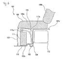
- FIG. 6 This embodiment is referred to as a second embodiment for the sake of convenience of description.
- the components same as those in the first embodiment are identified by the same numerals, and the description will not be repeated.
- FIG. 6 is a sectional view taken along the line A - A in FIG. 3 according to the present embodiment.
- the portion on the bottom surface of the seat portion 109a of the rear seat 109 and above the terminal 111a of the auxiliary battery 111 is recessed upward.
- the worker utilizes the space between the terminal 111a of the auxiliary battery 111 and the seat portion 109a of the rear seat 109, and the worker opens the detachable cover 122 to be capable of efficiently carrying out the operation of maintaining or exchanging the auxiliary battery 111.
- the efficient operation described above does not lead to the change in the appearance of the rear seat 109.
Landscapes
- Engineering & Computer Science (AREA)
- Mechanical Engineering (AREA)
- Transportation (AREA)
- Power Engineering (AREA)
- Chemical & Material Sciences (AREA)
- Life Sciences & Earth Sciences (AREA)
- Sustainable Development (AREA)
- Sustainable Energy (AREA)
- Combustion & Propulsion (AREA)
- General Chemical & Material Sciences (AREA)
- Electrochemistry (AREA)
- Chemical Kinetics & Catalysis (AREA)
- Arrangement Or Mounting Of Propulsion Units For Vehicles (AREA)
- Body Structure For Vehicles (AREA)
- Cooling, Air Intake And Gas Exhaust, And Fuel Tank Arrangements In Propulsion Units (AREA)
- Hybrid Electric Vehicles (AREA)
Abstract
Description
- The present invention relates to a hybrid vehicle including an engine and an electric motor, both of which are used as a power source.
- Conventionally, a hybrid vehicle including, as a power source, both an engine and an electric motor has mounted thereto a battery (hereinafter sometimes referred to as a "main battery") for feeding power to the electric motor. When the main battery is arranged in a vehicle compartment, it narrows the interior space where passengers or luggage are accommodated.
- A vehicle described in
Patent Literature 1 secures a mounting space of an electric storage device below a rear seat in order to prevent a comfort in the vehicle compartment from being deteriorated due to the electric storage device. ThePatent Literature 1 describes that not only a battery pack 600 but also another battery pack 2600 and a junction box 800 are mounted, and the battery pack 2600 is mounted on a top surface of a risingportion 110 as a third embodiment. -
- [Patent Literature 1] Specification of Japanese Patent No.
4225363 FIG. 6 ) - A hybrid vehicle may have mounted thereto another battery (hereinafter sometimes referred to as an "auxiliary battery") for assisting a power supply by the main battery in order to supply a voltage to accessories such as an ECU (electronic control unit) operating with a low voltage (e.g., 12 V) or in order to prepare for troubles such as low battery charge of the main battery. However, since the hybrid vehicle is provided with an engine and an inverter in an engine compartment at the front part of the vehicle, a sufficient space for arranging the auxiliary battery cannot be secured in the engine compartment. Therefore, the place where the auxiliary battery is mounted becomes a problem.
- As one example, it is considered that the auxiliary battery is mounted on the top surface of the rising portion of a floor panel at the rear of the rear seat as described in the
Patent Literature 1. In this case, an interior space at the rear of the rear seat is decreased (see paragraph 0065 in Patent Literature 1). - As another example, it is also considered that the auxiliary battery is arranged in a space enclosed by a rear panel at the rear of a wheel house of a rear tire. When the auxiliary battery is arranged at the rear of the wheel house of the rear tire, the auxiliary battery might be damaged, when the rear part of the vehicle is hit. The arrangement of the auxiliary battery described above can be realized only in a sedan vehicle having a long rear overhang, and in a compact hatch-back vehicle having a short rear overhang, this arrangement cannot be realized without narrowing a cargo room.
- The present invention aims to mount both a battery for driving an electric motor and a preparatory auxiliary battery to a hybrid vehicle without narrowing a cargo room.
- A hybrid vehicle according to the present invention includes: a floor panel including a rising portion that rises upward and extends in a widthwise direction of the vehicle, and a front portion that extends in a forward direction of the vehicle from the rising portion; a fuel tank that is mounted below the floor panel, and that stores liquid fuel burned in an engine serving as a power source of the vehicle; a rear seat provided above the floor panel with a seat portion which supports a hip of a passenger being opposite to the front portion; a first mounting portion that is formed in a housing space enclosed by the front portion, the seat portion, and the rising portion, so as to mount a first battery which stores driving power of an electric motor serving as the power source of the vehicle; and a second mounting portion that is formed in the housing space as being side by side with the first mounting portion in the widthwise direction of the vehicle so as to mount a second battery which assists a power supply by the first battery.
- According to the present invention, two batteries can be arranged side by side below a rear seat. Accordingly, both the main battery and the auxiliary battery can be mounted on the hybrid vehicle without narrowing the cargo room.
-
-
FIG. 1 is a plan view of a vehicle according to a first embodiment. -
FIG. 2 is a left sectional view of the vehicle. -
FIG. 3 is a plan view of the vehicle illustrating respective components below a rear seat. -
FIG. 4 is a sectional view taken along a line A - A inFIG. 3 . -
FIG. 5 is a sectional view taken along a line B - B inFIG. 3 . -
FIG. 6 is a sectional view taken along the line A - A inFIG. 3 according to a second embodiment. - One embodiment will be described with reference to
FIGS. 1 to 5 . For the sake of convenience of description, the present invention is referred to as a first embodiment.FIG. 1 is a plan view of avehicle 101. Thevehicle 101 is a hybrid type including an engine and an electric motor (both are not illustrated), both of which are used as a power source. Thevehicle 101 has an engine compartment (not illustrated) at its front part. In thevehicle 101, the engine, the electric motor, and an inverter (not illustrated) connected to the electric motor are mounted inside the engine compartment. - In the
vehicle 101, arear seat 109 is mounted. Thevehicle 101 has, provided below or at the rear of therear seat 109, afloor panel 102, aleft side member 103L, aright side member 103R, acenter cross member 104, a firstrear cross member 105, a secondrear cross member 106, a leftrear tire 107L, a rightrear tire 107R, asuspension member 108, amain battery 110 serving as a first battery, anauxiliary battery 111 serving as a second battery, afuel tank 112, and arear wheel house 114. - The
floor panel 102 forms a floor surface of the interior of thevehicle 101. Thefloor panel 102 has afront portion 102a extending toward the front part of thevehicle 101 as extending substantially horizontally, and arear portion 102b extending toward the rear of thevehicle 101. Thefloor panel 102 has a risingportion 102c between thefront portion 102a and therear portion 102b. The risingportion 102c projects upward from both thefront portion 102a and therear portion 102b of thefloor panel 102, and forms a ridge extending in the widthwise direction of thevehicle 101. The firstrear cross member 105 is positioned below the risingportion 102c. - The
rear seat 109 includes a seat portion 10 9a that supports a hip of a passenger, and abackrest portion 109b that supports a back of the passenger. Thebackrest portion 109b projects upward from a trailing end of theseat portion 109a. Therear seat 109 is positioned above thefloor panel 102 with the portion of the rear part of the lower surface of theseat portion 109a being supported by the risingportion 102c. In this case, theseat portion 109a is parallel to thefront portion 102a, and is opposite to thefront portion 102a. - A space in the
vehicle 101 at the rear of therear seat 109 is used as acargo room 113. Thebackrest portion 109b of therear seat 109 forms a front wall surface of thecargo room 113. The floor surface of thecargo room 113 is formed by therear portion 102b and a spare tire accommodatingportion cover 131. Specifically, a sparetire accommodating portion 133 for accommodating aspare tire 132 is formed to have a shape recessed downward at therear portion 102b of thefloor panel 102. The spare tireaccommodating portion cover 131 is positioned above thespare tire 132 accommodated in the sparetire accommodating portion 133, and it covers the sparetire accommodating portion 133 so as to form the flat floor surface of thecargo room 113. - The
rear wheel houses 114 are located at both right and left sides and at the rear part of thevehicle 101, and at both right and left sides of thecargo room 113, and they are arranged at the position at the rear of therear seat 109. Therear wheel house 114 projects upward from therear portion 102b of thefloor panel 102. A leftrear tire 107L is located below the leftrear wheel house 114 so as to be rotatable. A rightrear tire 107R is located below the rightrear wheel house 114 so as to be rotatable. The right and leftrear wheel houses 114 are covered by a rear panel (not illustrated) forming an outer appearance of thevehicle 101. - The
left side member 103L and theright side member 103R are members extending in the longitudinal direction of thevehicle 101, and they are attached to regions on right and left sides of thefloor panel 102. More specifically, theleft side member 103L includes a portion LA extending in the longitudinal direction of thevehicle 101 along a right side of the leftrear wheel house 114, a portion LB extending around from the portion LA toward an outer direction (leftward) of thevehicle 101 along the shape of the front part of the leftrear wheel house 114, and a portion LC extending from the portion LB toward the front part as making close to the outer direction of thevehicle 101. On the other hand, theright side member 103R has substantially a symmetrical shape with theleft side member 103L. Specifically, theleft side member 103L and theright side member 103R extend in the longitudinal direction so as to expand in the outer direction of thevehicle 101 from the rear part toward the front part of thevehicle 101. Theleft side member 103L and theright side member 103R are located below therear portion 102b of thefloor panel 102 at the portion LA, while projects upward from thefront portion 102a as being in contact with the side face of both sides of thefront portion 102a of thefloor panel 102 at the portion LC. - The
center cross member 104, the firstrear cross member 105, and the secondrear cross member 106 are arranged in this order from the front part toward the rear part of thevehicle 101. Thecenter cross member 104, the firstrear cross member 105, and the secondrear cross member 106 are attached on the bottom surface of thefloor panel 102, and have a shape extending in the widthwise direction of the vehicle for connecting theleft side member 103L and theright side member 103R, thereby enhancing rigidity of thevehicle 101. Thecenter cross member 104 will be described later with reference toFIGS. 3 and4 . The firstrear cross member 105 is mounted on the bottom surface of the risingportion 102c. The secondrear cross member 106 is mounted on the bottom surface of thefloor panel 102 at the rear end portion. - The
suspension member 108 is a component of a suspension system of thevehicle 101. Thesuspension member 108 includes a left trailingarm 115L, aright trailing arm 115R, and anintermediate beam 116. The trailing end of theleft trailing arm 115L is coupled to the leftrear tire 107L via a shock absorber and a coil spring (both are not illustrated). The front end of theleft trailing arm 115L is coupled to theleft side member 103L. Similarly, the trailing end of theright trailing arm 115R is coupled to the rightrear tire 107R via a shock absorber and a coil spring (both are not illustrated), and the front end of theright trailing arm 115R is coupled to theright side member 103R. The shock absorber and the coil spring absorb the vibration of the leftrear tire 107L and the rightrear tire 107R during when thevehicle 101 runs. Theintermediate beam 116 is located at the rear of therear seat 109 and below thefloor panel 102 for coupling theleft trailing arm 115L and theright trailing arm 115R. -
FIG. 2 is a left sectional view of thevehicle 101. Thefuel tank 112 stores liquid fuel that is burned in an engine (not illustrated) serving as a power source of thevehicle 101. The liquid fuel is, for example, gasoline or alcohol. Thefuel tank 112 has a filler tube (not illustrated) extending rearward and upward at the left end. Thefuel tank 112 also has a fill opening (not illustrated) at its upper end. Thefuel tank 112 is located below thefloor panel 102 so as to be housed in the risingportion 102c. Thefuel tank 112 is located between the left trailingarm 115L and theright trailing arm 115R as avoiding theleft trailing arm 115L, theright trailing arm 115R, the shock absorber, and the coil spring, and is fixed to theleft side member 103L and theright side member 103R. Thefuel tank 112 is located in front of the firstrear cross member 105 and theintermediate beam 116, and has a shape for avoiding the interference with these members. - The
seat portion 109a of therear seat 109, thefront portion 102a of thefloor panel 102, and the risingportion 102c of thefloor panel 102 form a housing space SP. A first mountingportion 151 for mounting themain battery 110, and a second mountingportion 152 for mounting theauxiliary battery 111 are formed side by side in the widthwise direction of the vehicle in the housing space SP. Themain battery 110 is mounted in the first mountingportion 151, while theauxiliary battery 111 is mounted in the second mountingportion 152, and they are positioned in the housing space SP. - The upper part, rear part, and both right and left side parts of the housing space SP are covered by a
frame 126. Theframe 126 is made of a metal mesh, and is formed to have a shape covering themain battery 110, theauxiliary battery 111, and ablower motor 119. The rear part of theframe 126 forms a part of the risingportion 102c, and is in contact with the front face of thewall face 102d standing upward from thefront portion 102a. The upper part of theframe 126 covers themain battery 110, theauxiliary battery 111, and theblower motor 119, and supports the bottom surface of theseat portion 109a of therear seat 109. - The
main battery 110, theauxiliary battery 111, and theblower motor 119 will be described here. Themain battery 110 has a casing having an elongate and substantially rectangular shape. A secondary battery formed by connecting in series plural battery modules, having plural battery cells connected in series, is stored in the casing so as to accumulate driving power of the electric motor (not illustrated). Themain battery 110 is arranged in the housing space SP in such a manner that the long side directs in the widthwise direction of thevehicle 101. Themain battery 110 has a terminal 110a on a surface of thevehicle 101 that directs leftward when themain battery 110 is stored in the housing space SP. Apipe 111b (seeFIG. 3 ) extends from the surface of thevehicle 101 that directs rightward when themain battery 110 is stored in the housing space SP. Thepipe 111b is for discharging hydrogen, generated in themain battery 110, to the outside of thevehicle 101. - The
main battery 110 is connected to the inverter (not illustrated) mounted to the engine compartment (not illustrated) via awiring 117a mounted to the terminal 110a. Thewiring 117a forms a part of awire harness 117. Themain battery 110 feeds electric power to various accessories (not illustrated), such as the electric motor, mounted to thevehicle 101, through the inverter. Electric power generated due to the drive of the motor is also stored in themain battery 110 via the inverter. - The
blower motor 119 is stored in the housing space SP so as to be arranged at the left side of themain battery 110. Theblower motor 119 is a drive source for a heater or an air conditioner (both are not illustrated) mounted to thevehicle 101, and further, blows cooling wind to themain battery 110 to cool themain battery 110. The length of themain battery 110 and theblower motor 119 in the widthwise direction of thevehicle 101 is substantially equal to a distance W (seeFIG. 1 ) between rear wheel houses 114. - The
auxiliary battery 111 is configured to store a secondary battery in a casing of substantially rectangular shape. A length of one side of the casing of theauxiliary battery 111 is substantially equal to a length V (seeFIG. 1 ) of therear wheel house 114 in the widthwise direction of the vehicle. Theauxiliary battery 111 assists the power supply from themain battery 110 to the respective components of thevehicle 101. The power of theauxiliary battery 111 is not used for driving thevehicle 101, but used for the electric voltage supply to the accessories such as the unillustrated ECU (electronic control unit) operated with a low voltage (e.g., 12 V) or theblower motor 119, or for the drive of each component of thevehicle 101 when themain battery 110 is not charged. Theauxiliary battery 111 has a terminal 111a (seeFIG. 4 ) on its upper surface. Anotherwiring 117b that forms a part of thewire harness 117 is mounted to thisterminal 111a. Specifically, theauxiliary battery 111 is connected in parallel to themain battery 110 with respect to the inverter provided in the engine compartment. Themain battery 110 and theauxiliary battery 111 may be connected in series. - A junction box (not illustrated) is electrically connected between the
main battery 110 and theauxiliary battery 111, and the inverter. The junction box has stored therein a system main relay for making a changeover between an electrical connection and disconnection between themain battery 110 and theauxiliary battery 111, and the inverter. Still anotherwiring 117c forming a part of thewire harness 117 is connected to a terminal (not illustrated) of theblower motor 119, and theblower motor 119 is driven by a power feeding from themain battery 110 and theauxiliary battery 111. A relay (not illustrated) is provided on the wiring that connects themain battery 110 and theblower motor 119. - The
main battery 110 and theblower motor 119, which are arranged side by side in the widthwise direction of the vehicle, occupies the width corresponding to the distance W (seeFIG. 1 ) as described above. Therefore, it is considered that themain battery 110 and theblower motor 119 are arranged in the vicinity of thebackrest portion 109b of therear seat 109 in thecargo room 113, for example. It is also considered that, since the length of one side of the casing of theauxiliary battery 111 is substantially equal to the length V (seeFIG. 1 ), the mounting space for theauxiliary battery 111 is formed at the rear of therear wheel house 114, and theauxiliary battery 111 mounted in this space is covered by a rear panel (not illustrated). It is also considered that the mounting space for theauxiliary battery 111 is formed so as to be adjacent to the mounting space for themain battery 110 and theblower motor 119 in thecargo room 113. -
FIG. 3 is a plan view of thevehicle 101 illustrating the components below therear seat 109.FIG. 3 virtually illustrates the position where theseat portion 109a of therear seat 109 is mounted with a one-dot-chain line. Theframe 126 is not illustrated inFIG. 3 . In the present embodiment, themain battery 110 and theauxiliary battery 111 are stored in the housing space SP. The height of the housing space SP is the height H (seeFIG. 2 ) of the risingportion 102c with respect to thefront portion 102a, so that it is higher than thefuel tank 112. - The
left side member 103L and theright side member 103R project upward from thefront portion 102a from both right and left sides of thefront portion 102a of thefloor panel 102, and form right and left wall faces of the housing space SP. Specifically, a side face 103La of theleft side member 103L forms a left wall face that defines the size of the housing space SP in the widthwise direction of the vehicle. A side face 103Ra of theright side member 103R forms a right wall face that defines the size of the housing space SP in the widthwise direction of the vehicle. Both of theleft side member 103L and theright side member 103R support the left and right sides of theseat portion 109a of therear seat 109 at their top surfaces. - The first mounting
portion 151 for mounting themain battery 110 and the second mountingportion 152 for mounting theauxiliary battery 111 are arranged side by side in the widthwise direction of the vehicle in the housing space SP and on the top surface of thefront portion 102a of thefloor panel 102. The first mountingportion 151 is formed in the housing space SP so as to be close to the side face 103La of theleft side member 103L. Thesecond mounting portion 152 is formed in the housing space SP and between the first mountingportion 151 and the side face 103Ra of theright side member 103R. A through-hole 120 through which thewire harness 117 extends is formed between the first mountingportion 151 and the side face 103La of theleft side member 103L, at thefront portion 102a of thefloor panel 102. -
FIG. 4 is a sectional view taken along a line A - A inFIG. 3 . Theauxiliary battery 111 is mounted in the second mountingportion 152 so as to be positioned below theseat portion 109a of therear seat 109 and above thefront portion 102a of thefloor panel 102. Theauxiliary battery 111 is positioned in the second mountingportion 152 by apositioning member 118, and fixed by a mounting member (not illustrated) so as not to move due to the vibration of thevehicle 101. The positioningmember 118 has a shape of holding theauxiliary battery 111, and is fixed on thefront portion 102a of thefloor panel 102. The positioningmember 118 has a shape of holding themain battery 110 and theblower motor 119, and positions themain battery 110 to the first mountingportion 151. -
FIGS. 3 and4 will be referred to. A fixingcover 121 for covering the front part of the housing space SP is located in front of themain battery 110. The fixingcover 121 hangs down from the front end of therear seat 109, and is connected to thefront portion 102a of thefloor panel 102. The right end of the fixingcover 121 substantially corresponds with the position of the right end of themain battery 110 mounted in the first mountingportion 151. The left end of the fixingcover 121 is connected to the side face 103La of theleft side member 103L. - An
opening 123 is formed at the right side of the fixingcover 121. Theopening 123 is open at the front of theauxiliary battery 111. The outer periphery of theopening 123 is formed by the bottom surface of theseat portion 109a of therear seat 109, the upper surface of thefront portion 102a of thefloor panel 102, the right end side of the fixingcover 121, and the side face 103Ra of theright side member 103R. Adetachable cover 122 opens and closes thisopening 123. For example, thedetachable cover 122 is coupled to the right end side of the fixingcover 121 via ahinge 124 so as to be swingable in the forward direction of thevehicle 101. As another example, thedetachable cover 122 may have a claw portion (not illustrated) engaged with the fixingcover 121 and the side face 103Ra of theright side member 103R, and the claw portion may be engaged with the fixingcover 121 and the side face 103Ra of theright side member 103R so as to prevent thedetachable cover 122 from being detached from theopening 123, when theopening 123 is closed. -
FIG. 5 is a sectional view taken along a line B - B inFIG. 3 . Thecenter cross member 104 is mounted on the bottom surface of thefloor panel 102 at the portion extending across thefront portion 102a and the risingportion 102c. Thecenter cross member 104 is a member extending in the widthwise direction of thevehicle 101 for linking theleft side member 103L and theright side member 103R. The section of thecenter cross member 104 has a U shape that is open upward. Theend portion 104a at the front part of thecenter cross member 104 is in contact with the bottom surface of thefront portion 102a. The end portion 104b at the rear of thecenter cross member 104 extends along thewall face 102d of the risingportion 102c extending in the vertical direction. Thecenter cross member 104 supports themain battery 110 mounted in the first mountingportion 151 via thefront portion 102a of thefloor panel 102. - When the
vehicle 101 thus configured is manufactured, thefuel tank 112 only has airtightness in order to store highly-volatile liquid fuel (such as, gasoline, alcohol) that is supplied to the engine, and the shape of thefuel tank 112 can relatively freely be formed. On the other hand, the degree of freedom in designing themain battery 110 and theauxiliary battery 111 is low. More specifically, themain battery 110 and theauxiliary battery 111 have stored therein plural battery cells and battery modules, so that the outer appearances thereof might be determined according to the shape of plural battery cells and battery modules and the connection position. Therefore, the degree of freedom in designing themain battery 110 and theauxiliary battery 111 is low. - In view of this, amanufacturer of the
vehicle 101 according to the present embodiment moves thewall face 102d of the risingportion 102c to the rear to make the wall face close to the firstrear cross member 105, and forms the risingportion 102c on thefloor panel 102 to decrease the housing space SP, in order to secure the housing space SP sufficient for mounting themain battery 110 and theauxiliary battery 111 side by side below theseat portion 109a of therear seat 109. Then, the manufacturer forms thefuel tank 112 into the shape fitted in the space enclosed by the firstrear cross member 105, theintermediate beam 116, and thewall face 102d of the risingportion 102c, and arranges thefuel tank 112 in this space. - Next, the manufacturer arranges the
main battery 110 in the first mountingportion 151 in the housing space SP and theauxiliary battery 111 in the second mountingportion 152, before mounting theseat portion 109a of therear seat 109. Since the first mountingportion 151 and the second mountingportion 152 are formed side by side in the widthwise direction of the vehicle in the housing space SP, the manufacturer arranges themain battery 110 and theauxiliary battery 111 in the respective portions. Thereafter, the manufacturer connects thewirings 117a to 177c of thewire harness 117 to the terminal 110a of themain battery 110, the terminal 111a of theauxiliary battery 111, and the connection terminal (not illustrated) of theblower motor 119, and inserts thewire harness 117 into the through-hole 120. Then, the manufacturer covers theframe 126 over the housing space SP, and fixes therear seat 109 on the risingportion 102c of thefloor panel 102, the upper surface of theleft side member 103L, and the upper surface of theright side member 103R. Thus, therear seat 109 is positioned above thefloor panel 102. Theframe 126 is in contact with the bottom surface of theseat portion 109a of therear seat 109 so as to support theseat portion 109a. - As described above, in the present embodiment, the housing space SP sufficient for storing the
main battery 110 and theauxiliary battery 111 side by side can be secured at the portion below therear seat 109, which portion is generally not used, in the internal structure of thevehicle 101 in which various components are fixedly mounted, which leads to low degree of freedom in the design. Themain battery 110 and theauxiliary battery 111 are arranged side by side in this housing space SP. As a result, themain battery 110 and theauxiliary battery 111 are not arranged in thecargo room 113, which prevents thecargo room 113 from being narrowed. Themain battery 110 and theauxiliary battery 111 are enclosed by thefloor panel 102, therear seat 109, the fixingcover 121, thedetachable cover 122, theleft side member 103L, and theright side member 103R, which makes them dustproof and which protects them against the cold. Since theauxiliary battery 111 is arranged near themain battery 110, the length of thewire harness 117 can be shortened, whereby the weight of thevehicle 101 and the production cost can also be reduced. The relay (not illustrated) linking themain battery 110 and theauxiliary battery 111 is also simplified. Further, there is no chance that theauxiliary battery 111 is mounted at the rear of therear wheel house 114 that is liable to be hit. Specifically, the structure in which theauxiliary battery 111 is stored below therear seat 109 according to the present embodiment is also applicable to a compact hatch-back vehicle having a short rear overhang, and hence, the degree of freedom in designing the outer appearance of thevehicle 101 is increased. - In the present embodiment, the
fuel tank 112 is stored in the risingportion 102c. Therefore, the height of thevehicle 101 is reduced. Themain battery 110 and theauxiliary battery 111 are arranged at the position near the driving surface of thevehicle 101 below therear seat 109, and they are collectively arranged in the housing space SP, whereby the position of the center of gravity of thevehicle 101 becomes low, and the stable driving of thevehicle 101 can be realized. Since themain battery 110, theauxiliary battery 111, and thefuel tank 112 are all collectively arranged at the central part and lower part of thevehicle 101, it can be prevented that thevehicle 101 is broken due to the shock applied to thevehicle 101 by a hit, without applying a special reinforcement. - In the present embodiment, the
center cross member 104 not only connects theleft side member 103L and theright side member 103R so as to enhance the rigidity of thevehicle 101, but also supports themain battery 110. Therefore, it becomes unnecessary to make thefloor panel 102 strong in order to allow thefloor panel 102 to endure the weight upon mounting themain battery 110. - In the present embodiment, a worker can easily maintain or exchange the
auxiliary battery 111 by opening and closing thedetachable cover 122. - Next, another embodiment of the present invention will be described with reference to
FIG. 6 . This embodiment is referred to as a second embodiment for the sake of convenience of description. In the present embodiment, the components same as those in the first embodiment are identified by the same numerals, and the description will not be repeated. -
FIG. 6 is a sectional view taken along the line A - A inFIG. 3 according to the present embodiment. In the present embodiment, the portion on the bottom surface of theseat portion 109a of therear seat 109 and above the terminal 111a of theauxiliary battery 111 is recessed upward. - In the present embodiment, the worker utilizes the space between the terminal 111a of the
auxiliary battery 111 and theseat portion 109a of therear seat 109, and the worker opens thedetachable cover 122 to be capable of efficiently carrying out the operation of maintaining or exchanging theauxiliary battery 111. The efficient operation described above does not lead to the change in the appearance of therear seat 109. Reference Signs List -
- 101
- Hybrid vehicle
- 102
- Floor panel
- 102a
- Front portion
- 102c
- Rising portion
- 104
- Center cross member
- 112
- Fuel tank
- 109
- Rear seat
- 109a
- Seat portion
- 110
- Main battery (first battery)
- 111
- Auxiliary battery (second battery)
- 121
- Fixing cover
- 122
- Detachable cover
- 151
- First mounting portion
- 152
- Second mounting portion
- SP
- Housing space
Claims (5)
- A hybrid vehicle comprising:a floor panel including a rising portion that rises upward and extends in a widthwise direction of a vehicle, and a front portion that extends in a forward direction of the vehicle from the rising portion;a fuel tank that is mounted below the floor panel, and that stores liquid fuel burned in an engine serving as a power source of the vehicle;a rear seat provided above the floor panel with a seat portion that supports a hip of a passenger being opposite to the front portion;a first mounting portion that is formed in a housing space enclosed by the front portion, the seat portion, and the rising portion, so as to mount a first battery which stores driving power of an electric motor serving as the power source of the vehicle; anda second mounting portion that is formed in the housing space as being side by side with the first mounting portion in the widthwise direction of the vehicle so as to mount a second battery which assists a power supply by the first battery.
- The hybrid vehicle according claim 1, further comprising:left and right side members, which extend in a longitudinal direction of the vehicle, and project upward from each of left and right sides of the front portion so as to support left and right sides of the seat portion of the rear seat with the top surfaces and define the side faces of the housing space in the widthwise direction of the vehicle.
- A hybrid vehicle according to claim 1 or claim 2, further comprising:a center cross member that is provided below the floor panel, and extends in the widthwise direction of the vehicle so as to support the first battery mounted in the first mounting portion through the floor panel.
- A hybrid vehicle according to any one of claims 1 to 3, further comprising:a cover that is mounted in front of the first mounting portion and the second mounting portion for covering a front of the housing space.
- A hybrid vehicle according to claim 4,
wherein a portion of the cover at a front of the second mounting portion can be opened and closed.
Applications Claiming Priority (2)
| Application Number | Priority Date | Filing Date | Title |
|---|---|---|---|
| JP2009148734A JP5001982B2 (en) | 2009-06-23 | 2009-06-23 | Hybrid type vehicle |
| PCT/JP2010/002704 WO2010150447A1 (en) | 2009-06-23 | 2010-04-14 | Hybrid vehicle |
Publications (3)
| Publication Number | Publication Date |
|---|---|
| EP2447100A1 true EP2447100A1 (en) | 2012-05-02 |
| EP2447100A4 EP2447100A4 (en) | 2018-04-11 |
| EP2447100B1 EP2447100B1 (en) | 2019-08-14 |
Family
ID=43386237
Family Applications (1)
| Application Number | Title | Priority Date | Filing Date |
|---|---|---|---|
| EP10791774.2A Active EP2447100B1 (en) | 2009-06-23 | 2010-04-14 | Hybrid vehicle |
Country Status (5)
| Country | Link |
|---|---|
| US (1) | US8794365B2 (en) |
| EP (1) | EP2447100B1 (en) |
| JP (1) | JP5001982B2 (en) |
| CN (1) | CN102802988B (en) |
| WO (1) | WO2010150447A1 (en) |
Cited By (1)
| Publication number | Priority date | Publication date | Assignee | Title |
|---|---|---|---|---|
| EP3190032A1 (en) * | 2015-12-24 | 2017-07-12 | Toyota Jidosha Kabushiki Kaisha | Vehicle rear portion structure |
Families Citing this family (33)
| Publication number | Priority date | Publication date | Assignee | Title |
|---|---|---|---|---|
| DE102009031779A1 (en) * | 2009-07-06 | 2011-01-13 | GM Global Technology Operations, Inc., Detroit | Floor structure for a motor vehicle |
| JP5071538B2 (en) * | 2010-09-03 | 2012-11-14 | トヨタ自動車株式会社 | Battery mounting structure for vehicles |
| DE102010051745B4 (en) * | 2010-11-19 | 2012-06-28 | Benteler Automobiltechnik Gmbh | Car with protection component |
| JP5652719B2 (en) * | 2011-05-02 | 2015-01-14 | スズキ株式会社 | Fuel cell vehicle |
| US20130051104A1 (en) * | 2011-08-23 | 2013-02-28 | Hitachi Koki Co., Ltd. | Battery Adapter and Power Source Device Employing Same |
| JP5659306B2 (en) * | 2011-11-17 | 2015-01-28 | 本田技研工業株式会社 | Electric vehicle |
| JP5760992B2 (en) * | 2011-11-29 | 2015-08-12 | トヨタ自動車株式会社 | Vehicle battery mounting structure |
| JP5983063B2 (en) * | 2012-06-08 | 2016-08-31 | スズキ株式会社 | In-vehicle structure of battery pack |
| JP5810058B2 (en) * | 2012-09-18 | 2015-11-11 | 本田技研工業株式会社 | Hybrid vehicle |
| JP5660111B2 (en) * | 2012-11-30 | 2015-01-28 | トヨタ自動車株式会社 | Cable routing structure in the motor room of an electric vehicle |
| WO2015045106A1 (en) * | 2013-09-27 | 2015-04-02 | 株式会社小松製作所 | Work vehicle |
| JP2015151045A (en) * | 2014-02-17 | 2015-08-24 | トヨタ紡織株式会社 | Seat for automobile |
| JP6610876B2 (en) * | 2015-11-11 | 2019-11-27 | 三菱自動車エンジニアリング株式会社 | Vehicle equipped with transpiration fuel processing equipment |
| US10632857B2 (en) | 2016-08-17 | 2020-04-28 | Shape Corp. | Battery support and protection structure for a vehicle |
| JP6460068B2 (en) * | 2016-09-05 | 2019-01-30 | トヨタ自動車株式会社 | vehicle |
| JP6419123B2 (en) * | 2016-09-13 | 2018-11-07 | 本田技研工業株式会社 | Power equipment unit and vehicle |
| CN110383526A (en) | 2017-01-04 | 2019-10-25 | 形状集团 | Node Modular Vehicle Battery Tray Structure |
| US10886513B2 (en) | 2017-05-16 | 2021-01-05 | Shape Corp. | Vehicle battery tray having tub-based integration |
| US10483510B2 (en) | 2017-05-16 | 2019-11-19 | Shape Corp. | Polarized battery tray for a vehicle |
| WO2018213383A1 (en) | 2017-05-16 | 2018-11-22 | Shape Corp. | Vehicle battery tray with integrated battery retention and support features |
| JP6969214B2 (en) * | 2017-08-09 | 2021-11-24 | トヨタ自動車株式会社 | Body structure |
| US12347879B2 (en) | 2017-09-13 | 2025-07-01 | Shape Corp. | Vehicle battery tray with tubular peripheral wall |
| CN111108015A (en) | 2017-09-13 | 2020-05-05 | 形状集团 | Vehicle battery tray with tubular peripheral wall |
| WO2019071013A1 (en) | 2017-10-04 | 2019-04-11 | Shape Corp. | Battery tray floor assembly for electric vehicles |
| US10787203B2 (en) * | 2018-01-03 | 2020-09-29 | Ford Global Technologies, Llc | Hybrid energy storage and delivery devices for hybrid electric vehicles |
| EP3759761B1 (en) | 2018-03-01 | 2026-04-08 | Shape Corp. | Cooling system integrated with vehicle battery tray |
| US11688910B2 (en) | 2018-03-15 | 2023-06-27 | Shape Corp. | Vehicle battery tray having tub-based component |
| JP7067291B2 (en) * | 2018-06-11 | 2022-05-16 | トヨタ自動車株式会社 | Rear structure of the vehicle |
| JP7200852B2 (en) | 2019-06-28 | 2023-01-10 | トヨタ自動車株式会社 | electric vehicle |
| KR102703281B1 (en) | 2019-07-23 | 2024-09-04 | 현대자동차주식회사 | A hybrid vehicle having an improved arrangement structure |
| KR102842792B1 (en) | 2019-08-08 | 2025-08-05 | 현대자동차 주식회사 | Battery and fuel tank arrangement structure of hybrid vehicle |
| CN112406565B (en) * | 2020-11-30 | 2022-02-01 | 安徽江淮汽车集团股份有限公司 | Impact type battery pack and new energy automobile |
| JP2024124101A (en) * | 2023-03-02 | 2024-09-12 | 株式会社小松製作所 | Battery-powered hydraulic excavator |
Family Cites Families (16)
| Publication number | Priority date | Publication date | Assignee | Title |
|---|---|---|---|---|
| JPH03109126A (en) * | 1989-09-21 | 1991-05-09 | Yamaha Motor Co Ltd | Electric automobile using fuel battery |
| JPH0480204U (en) | 1990-11-23 | 1992-07-13 | ||
| JP3879339B2 (en) * | 1999-11-17 | 2007-02-14 | マツダ株式会社 | Lower body structure of the vehicle |
| JP3741586B2 (en) * | 2000-03-30 | 2006-02-01 | ダイハツ工業株式会社 | Body structure around the seat in an automobile |
| JP2002165308A (en) * | 2000-11-21 | 2002-06-07 | Yamaha Motor Co Ltd | Electric vehicle |
| JP2002166728A (en) * | 2000-11-30 | 2002-06-11 | Toyota Auto Body Co Ltd | Cooling structure of high voltage battery |
| JP2004161158A (en) * | 2002-11-14 | 2004-06-10 | Nissan Motor Co Ltd | Battery mounting structure for electric vehicles |
| JP4519516B2 (en) * | 2003-07-15 | 2010-08-04 | 本田技研工業株式会社 | Heating / cooling device for vehicle electrical unit and hybrid vehicle |
| JP4081024B2 (en) * | 2004-01-20 | 2008-04-23 | 本田技研工業株式会社 | Fuel cell system mounting structure on vehicle |
| JP4649849B2 (en) * | 2004-03-02 | 2011-03-16 | トヨタ自動車株式会社 | Storage mechanism mounting structure |
| CN100508273C (en) * | 2005-06-02 | 2009-07-01 | 本田技研工业株式会社 | Power supply device for vehicle and cooling structure for battery |
| JP4825583B2 (en) * | 2005-06-28 | 2011-11-30 | 本田技研工業株式会社 | Body structure |
| CN100581867C (en) * | 2006-12-28 | 2010-01-20 | 奇瑞汽车股份有限公司 | Fuel battery power system of mixed power vehicle |
| JP2008239067A (en) * | 2007-03-28 | 2008-10-09 | Toyota Motor Corp | Car |
| JP4225363B2 (en) * | 2007-07-24 | 2009-02-18 | トヨタ自動車株式会社 | Vehicle equipped with internal combustion engine and rotating electric machine as power source |
| DE102008051786A1 (en) * | 2007-10-18 | 2009-04-23 | Volkswagen Ag | Electrically operatable motor vehicle, has container accommodating process materials for operating fuel cell system, and sectionally placed within transmission tunnel, where tunnel is strengthened by two longitudinal carriers |
-
2009
- 2009-06-23 JP JP2009148734A patent/JP5001982B2/en active Active
-
2010
- 2010-04-14 US US13/138,980 patent/US8794365B2/en not_active Expired - Fee Related
- 2010-04-14 EP EP10791774.2A patent/EP2447100B1/en active Active
- 2010-04-14 WO PCT/JP2010/002704 patent/WO2010150447A1/en not_active Ceased
- 2010-04-14 CN CN201080028175.3A patent/CN102802988B/en active Active
Non-Patent Citations (1)
| Title |
|---|
| See references of WO2010150447A1 * |
Cited By (1)
| Publication number | Priority date | Publication date | Assignee | Title |
|---|---|---|---|---|
| EP3190032A1 (en) * | 2015-12-24 | 2017-07-12 | Toyota Jidosha Kabushiki Kaisha | Vehicle rear portion structure |
Also Published As
| Publication number | Publication date |
|---|---|
| JP2011005889A (en) | 2011-01-13 |
| US8794365B2 (en) | 2014-08-05 |
| EP2447100B1 (en) | 2019-08-14 |
| JP5001982B2 (en) | 2012-08-15 |
| US20120055722A1 (en) | 2012-03-08 |
| CN102802988A (en) | 2012-11-28 |
| CN102802988B (en) | 2016-06-01 |
| EP2447100A4 (en) | 2018-04-11 |
| WO2010150447A1 (en) | 2010-12-29 |
Similar Documents
| Publication | Publication Date | Title |
|---|---|---|
| EP2447100B1 (en) | Hybrid vehicle | |
| KR102835262B1 (en) | Under Body for Vehicle | |
| US9174520B2 (en) | Electric vehicle | |
| US11034248B2 (en) | Battery case fixing structure | |
| KR101273080B1 (en) | Mounting structure for battery in electric vehicle | |
| CN101754880B (en) | Vehicles including internal combustion engines and rotating electric machines as power sources | |
| JP5656020B2 (en) | High-voltage cable routing structure for electric vehicles | |
| US8012620B2 (en) | Structure for mounting batteries onto electric vehicles | |
| US7931105B2 (en) | Structure for mounting batteries onto electric vehicles | |
| JP5760992B2 (en) | Vehicle battery mounting structure | |
| EP2767427B1 (en) | Structure for mounting electric power storage device | |
| JP5983058B2 (en) | Electric vehicle battery pack mounting structure | |
| CN108367660A (en) | The loading structure of high voltage control device unit | |
| CN104010884B (en) | There is the hydraulic hybrid power vehicles of the energy storage disposed in an optimized way | |
| CN110920372A (en) | High voltage battery support and isolation for an electric vehicle | |
| JP6688851B2 (en) | vehicle | |
| JP2007069801A (en) | Power supply device mounting structure | |
| US12151584B2 (en) | Working vehicle | |
| CN110182262B (en) | Vehicle lower structure | |
| US12187111B2 (en) | Lower structure for vehicle | |
| JP2004243882A (en) | Mounting structure of electrical equipment for vehicles | |
| US12427846B2 (en) | Vehicle-body front structure including a contactless charger | |
| CN103298636B (en) | electric car | |
| JP6525657B2 (en) | Automotive battery | |
| JP6629515B2 (en) | Automotive battery |
Legal Events
| Date | Code | Title | Description |
|---|---|---|---|
| PUAI | Public reference made under article 153(3) epc to a published international application that has entered the european phase |
Free format text: ORIGINAL CODE: 0009012 |
|
| 17P | Request for examination filed |
Effective date: 20120120 |
|
| AK | Designated contracting states |
Kind code of ref document: A1 Designated state(s): AT BE BG CH CY CZ DE DK EE ES FI FR GB GR HR HU IE IS IT LI LT LU LV MC MK MT NL NO PL PT RO SE SI SK SM TR |
|
| DAX | Request for extension of the european patent (deleted) | ||
| RAP1 | Party data changed (applicant data changed or rights of an application transferred) |
Owner name: TOYOTA JIDOSHA KABUSHIKI KAISHA Owner name: TOYOTA MOTOR EAST JAPAN, INC. |
|
| RAP1 | Party data changed (applicant data changed or rights of an application transferred) |
Owner name: TOYOTA MOTOR EAST JAPAN, INC. Owner name: TOYOTA JIDOSHA KABUSHIKI KAISHA |
|
| RA4 | Supplementary search report drawn up and despatched (corrected) |
Effective date: 20180314 |
|
| RIC1 | Information provided on ipc code assigned before grant |
Ipc: B62D 25/20 20060101ALI20180308BHEP Ipc: B60R 16/04 20060101ALI20180308BHEP Ipc: B60K 1/04 20060101ALI20180308BHEP Ipc: B60K 6/28 20071001ALI20180308BHEP Ipc: B60K 15/063 20060101ALI20180308BHEP Ipc: B60K 6/40 20071001AFI20180308BHEP |
|
| RIC1 | Information provided on ipc code assigned before grant |
Ipc: B60R 16/04 20060101ALI20180308BHEP Ipc: B60K 1/04 20190101ALI20180308BHEP Ipc: B60K 6/28 20071001ALI20180308BHEP Ipc: B60K 6/40 20071001AFI20180308BHEP Ipc: B62D 25/20 20060101ALI20180308BHEP Ipc: B60K 15/063 20060101ALI20180308BHEP |
|
| GRAP | Despatch of communication of intention to grant a patent |
Free format text: ORIGINAL CODE: EPIDOSNIGR1 |
|
| STAA | Information on the status of an ep patent application or granted ep patent |
Free format text: STATUS: GRANT OF PATENT IS INTENDED |
|
| INTG | Intention to grant announced |
Effective date: 20190301 |
|
| GRAS | Grant fee paid |
Free format text: ORIGINAL CODE: EPIDOSNIGR3 |
|
| GRAA | (expected) grant |
Free format text: ORIGINAL CODE: 0009210 |
|
| STAA | Information on the status of an ep patent application or granted ep patent |
Free format text: STATUS: THE PATENT HAS BEEN GRANTED |
|
| AK | Designated contracting states |
Kind code of ref document: B1 Designated state(s): AT BE BG CH CY CZ DE DK EE ES FI FR GB GR HR HU IE IS IT LI LT LU LV MC MK MT NL NO PL PT RO SE SI SK SM TR |
|
| REG | Reference to a national code |
Ref country code: GB Ref legal event code: FG4D |
|
| REG | Reference to a national code |
Ref country code: CH Ref legal event code: EP Ref country code: AT Ref legal event code: REF Ref document number: 1166605 Country of ref document: AT Kind code of ref document: T Effective date: 20190815 |
|
| REG | Reference to a national code |
Ref country code: IE Ref legal event code: FG4D |
|
| REG | Reference to a national code |
Ref country code: DE Ref legal event code: R096 Ref document number: 602010060578 Country of ref document: DE |
|
| REG | Reference to a national code |
Ref country code: NL Ref legal event code: MP Effective date: 20190814 |
|
| REG | Reference to a national code |
Ref country code: LT Ref legal event code: MG4D |
|
| PG25 | Lapsed in a contracting state [announced via postgrant information from national office to epo] |
Ref country code: PT Free format text: LAPSE BECAUSE OF FAILURE TO SUBMIT A TRANSLATION OF THE DESCRIPTION OR TO PAY THE FEE WITHIN THE PRESCRIBED TIME-LIMIT Effective date: 20191216 Ref country code: NO Free format text: LAPSE BECAUSE OF FAILURE TO SUBMIT A TRANSLATION OF THE DESCRIPTION OR TO PAY THE FEE WITHIN THE PRESCRIBED TIME-LIMIT Effective date: 20191114 Ref country code: SE Free format text: LAPSE BECAUSE OF FAILURE TO SUBMIT A TRANSLATION OF THE DESCRIPTION OR TO PAY THE FEE WITHIN THE PRESCRIBED TIME-LIMIT Effective date: 20190814 Ref country code: HR Free format text: LAPSE BECAUSE OF FAILURE TO SUBMIT A TRANSLATION OF THE DESCRIPTION OR TO PAY THE FEE WITHIN THE PRESCRIBED TIME-LIMIT Effective date: 20190814 Ref country code: NL Free format text: LAPSE BECAUSE OF FAILURE TO SUBMIT A TRANSLATION OF THE DESCRIPTION OR TO PAY THE FEE WITHIN THE PRESCRIBED TIME-LIMIT Effective date: 20190814 Ref country code: BG Free format text: LAPSE BECAUSE OF FAILURE TO SUBMIT A TRANSLATION OF THE DESCRIPTION OR TO PAY THE FEE WITHIN THE PRESCRIBED TIME-LIMIT Effective date: 20191114 Ref country code: LT Free format text: LAPSE BECAUSE OF FAILURE TO SUBMIT A TRANSLATION OF THE DESCRIPTION OR TO PAY THE FEE WITHIN THE PRESCRIBED TIME-LIMIT Effective date: 20190814 Ref country code: FI Free format text: LAPSE BECAUSE OF FAILURE TO SUBMIT A TRANSLATION OF THE DESCRIPTION OR TO PAY THE FEE WITHIN THE PRESCRIBED TIME-LIMIT Effective date: 20190814 |
|
| REG | Reference to a national code |
Ref country code: AT Ref legal event code: MK05 Ref document number: 1166605 Country of ref document: AT Kind code of ref document: T Effective date: 20190814 |
|
| PG25 | Lapsed in a contracting state [announced via postgrant information from national office to epo] |
Ref country code: ES Free format text: LAPSE BECAUSE OF FAILURE TO SUBMIT A TRANSLATION OF THE DESCRIPTION OR TO PAY THE FEE WITHIN THE PRESCRIBED TIME-LIMIT Effective date: 20190814 Ref country code: GR Free format text: LAPSE BECAUSE OF FAILURE TO SUBMIT A TRANSLATION OF THE DESCRIPTION OR TO PAY THE FEE WITHIN THE PRESCRIBED TIME-LIMIT Effective date: 20191115 Ref country code: IS Free format text: LAPSE BECAUSE OF FAILURE TO SUBMIT A TRANSLATION OF THE DESCRIPTION OR TO PAY THE FEE WITHIN THE PRESCRIBED TIME-LIMIT Effective date: 20191214 Ref country code: LV Free format text: LAPSE BECAUSE OF FAILURE TO SUBMIT A TRANSLATION OF THE DESCRIPTION OR TO PAY THE FEE WITHIN THE PRESCRIBED TIME-LIMIT Effective date: 20190814 |
|
| PG25 | Lapsed in a contracting state [announced via postgrant information from national office to epo] |
Ref country code: TR Free format text: LAPSE BECAUSE OF FAILURE TO SUBMIT A TRANSLATION OF THE DESCRIPTION OR TO PAY THE FEE WITHIN THE PRESCRIBED TIME-LIMIT Effective date: 20190814 |
|
| PG25 | Lapsed in a contracting state [announced via postgrant information from national office to epo] |
Ref country code: RO Free format text: LAPSE BECAUSE OF FAILURE TO SUBMIT A TRANSLATION OF THE DESCRIPTION OR TO PAY THE FEE WITHIN THE PRESCRIBED TIME-LIMIT Effective date: 20190814 Ref country code: IT Free format text: LAPSE BECAUSE OF FAILURE TO SUBMIT A TRANSLATION OF THE DESCRIPTION OR TO PAY THE FEE WITHIN THE PRESCRIBED TIME-LIMIT Effective date: 20190814 Ref country code: AT Free format text: LAPSE BECAUSE OF FAILURE TO SUBMIT A TRANSLATION OF THE DESCRIPTION OR TO PAY THE FEE WITHIN THE PRESCRIBED TIME-LIMIT Effective date: 20190814 Ref country code: EE Free format text: LAPSE BECAUSE OF FAILURE TO SUBMIT A TRANSLATION OF THE DESCRIPTION OR TO PAY THE FEE WITHIN THE PRESCRIBED TIME-LIMIT Effective date: 20190814 Ref country code: PL Free format text: LAPSE BECAUSE OF FAILURE TO SUBMIT A TRANSLATION OF THE DESCRIPTION OR TO PAY THE FEE WITHIN THE PRESCRIBED TIME-LIMIT Effective date: 20190814 Ref country code: DK Free format text: LAPSE BECAUSE OF FAILURE TO SUBMIT A TRANSLATION OF THE DESCRIPTION OR TO PAY THE FEE WITHIN THE PRESCRIBED TIME-LIMIT Effective date: 20190814 |
|
| PG25 | Lapsed in a contracting state [announced via postgrant information from national office to epo] |
Ref country code: IS Free format text: LAPSE BECAUSE OF FAILURE TO SUBMIT A TRANSLATION OF THE DESCRIPTION OR TO PAY THE FEE WITHIN THE PRESCRIBED TIME-LIMIT Effective date: 20200224 Ref country code: SK Free format text: LAPSE BECAUSE OF FAILURE TO SUBMIT A TRANSLATION OF THE DESCRIPTION OR TO PAY THE FEE WITHIN THE PRESCRIBED TIME-LIMIT Effective date: 20190814 Ref country code: SM Free format text: LAPSE BECAUSE OF FAILURE TO SUBMIT A TRANSLATION OF THE DESCRIPTION OR TO PAY THE FEE WITHIN THE PRESCRIBED TIME-LIMIT Effective date: 20190814 Ref country code: CZ Free format text: LAPSE BECAUSE OF FAILURE TO SUBMIT A TRANSLATION OF THE DESCRIPTION OR TO PAY THE FEE WITHIN THE PRESCRIBED TIME-LIMIT Effective date: 20190814 |
|
| REG | Reference to a national code |
Ref country code: DE Ref legal event code: R097 Ref document number: 602010060578 Country of ref document: DE |
|
| PLBE | No opposition filed within time limit |
Free format text: ORIGINAL CODE: 0009261 |
|
| STAA | Information on the status of an ep patent application or granted ep patent |
Free format text: STATUS: NO OPPOSITION FILED WITHIN TIME LIMIT |
|
| PG2D | Information on lapse in contracting state deleted |
Ref country code: IS |
|
| 26N | No opposition filed |
Effective date: 20200603 |
|
| PG25 | Lapsed in a contracting state [announced via postgrant information from national office to epo] |
Ref country code: SI Free format text: LAPSE BECAUSE OF FAILURE TO SUBMIT A TRANSLATION OF THE DESCRIPTION OR TO PAY THE FEE WITHIN THE PRESCRIBED TIME-LIMIT Effective date: 20190814 |
|
| PG25 | Lapsed in a contracting state [announced via postgrant information from national office to epo] |
Ref country code: MC Free format text: LAPSE BECAUSE OF FAILURE TO SUBMIT A TRANSLATION OF THE DESCRIPTION OR TO PAY THE FEE WITHIN THE PRESCRIBED TIME-LIMIT Effective date: 20190814 |
|
| REG | Reference to a national code |
Ref country code: CH Ref legal event code: PL |
|
| PG25 | Lapsed in a contracting state [announced via postgrant information from national office to epo] |
Ref country code: LU Free format text: LAPSE BECAUSE OF NON-PAYMENT OF DUE FEES Effective date: 20200414 Ref country code: LI Free format text: LAPSE BECAUSE OF NON-PAYMENT OF DUE FEES Effective date: 20200430 Ref country code: CH Free format text: LAPSE BECAUSE OF NON-PAYMENT OF DUE FEES Effective date: 20200430 |
|
| REG | Reference to a national code |
Ref country code: BE Ref legal event code: MM Effective date: 20200430 |
|
| PG25 | Lapsed in a contracting state [announced via postgrant information from national office to epo] |
Ref country code: BE Free format text: LAPSE BECAUSE OF NON-PAYMENT OF DUE FEES Effective date: 20200430 |
|
| PG25 | Lapsed in a contracting state [announced via postgrant information from national office to epo] |
Ref country code: IE Free format text: LAPSE BECAUSE OF NON-PAYMENT OF DUE FEES Effective date: 20200414 |
|
| PGFP | Annual fee paid to national office [announced via postgrant information from national office to epo] |
Ref country code: GB Payment date: 20220303 Year of fee payment: 13 |
|
| PG25 | Lapsed in a contracting state [announced via postgrant information from national office to epo] |
Ref country code: MT Free format text: LAPSE BECAUSE OF FAILURE TO SUBMIT A TRANSLATION OF THE DESCRIPTION OR TO PAY THE FEE WITHIN THE PRESCRIBED TIME-LIMIT Effective date: 20190814 Ref country code: CY Free format text: LAPSE BECAUSE OF FAILURE TO SUBMIT A TRANSLATION OF THE DESCRIPTION OR TO PAY THE FEE WITHIN THE PRESCRIBED TIME-LIMIT Effective date: 20190814 |
|
| PGFP | Annual fee paid to national office [announced via postgrant information from national office to epo] |
Ref country code: FR Payment date: 20220308 Year of fee payment: 13 |
|
| PG25 | Lapsed in a contracting state [announced via postgrant information from national office to epo] |
Ref country code: MK Free format text: LAPSE BECAUSE OF FAILURE TO SUBMIT A TRANSLATION OF THE DESCRIPTION OR TO PAY THE FEE WITHIN THE PRESCRIBED TIME-LIMIT Effective date: 20190814 |
|
| P01 | Opt-out of the competence of the unified patent court (upc) registered |
Effective date: 20230427 |
|
| GBPC | Gb: european patent ceased through non-payment of renewal fee |
Effective date: 20230414 |
|
| PG25 | Lapsed in a contracting state [announced via postgrant information from national office to epo] |
Ref country code: GB Free format text: LAPSE BECAUSE OF NON-PAYMENT OF DUE FEES Effective date: 20230414 |
|
| PG25 | Lapsed in a contracting state [announced via postgrant information from national office to epo] |
Ref country code: GB Free format text: LAPSE BECAUSE OF NON-PAYMENT OF DUE FEES Effective date: 20230414 Ref country code: FR Free format text: LAPSE BECAUSE OF NON-PAYMENT OF DUE FEES Effective date: 20230430 |
|
| PGFP | Annual fee paid to national office [announced via postgrant information from national office to epo] |
Ref country code: DE Payment date: 20250305 Year of fee payment: 16 |