JP6525657B2 - Automotive battery - Google Patents
Automotive battery Download PDFInfo
- Publication number
- JP6525657B2 JP6525657B2 JP2015062491A JP2015062491A JP6525657B2 JP 6525657 B2 JP6525657 B2 JP 6525657B2 JP 2015062491 A JP2015062491 A JP 2015062491A JP 2015062491 A JP2015062491 A JP 2015062491A JP 6525657 B2 JP6525657 B2 JP 6525657B2
- Authority
- JP
- Japan
- Prior art keywords
- control device
- storage case
- battery module
- reinforcing bar
- battery
- Prior art date
- Legal status (The legal status is an assumption and is not a legal conclusion. Google has not performed a legal analysis and makes no representation as to the accuracy of the status listed.)
- Active
Links
- 230000003014 reinforcing effect Effects 0.000 claims description 93
- 230000002787 reinforcement Effects 0.000 claims description 6
- 239000000725 suspension Substances 0.000 claims description 6
- 230000004308 accommodation Effects 0.000 claims 3
- 230000006870 function Effects 0.000 description 25
- 238000001816 cooling Methods 0.000 description 20
- 239000007789 gas Substances 0.000 description 8
- 239000000779 smoke Substances 0.000 description 5
- 230000035939 shock Effects 0.000 description 4
- 239000006096 absorbing agent Substances 0.000 description 3
- 239000000758 substrate Substances 0.000 description 3
- 239000013585 weight reducing agent Substances 0.000 description 3
- PXHVJJICTQNCMI-UHFFFAOYSA-N Nickel Chemical compound [Ni] PXHVJJICTQNCMI-UHFFFAOYSA-N 0.000 description 2
- 230000005856 abnormality Effects 0.000 description 2
- 238000001125 extrusion Methods 0.000 description 2
- 238000007689 inspection Methods 0.000 description 2
- 230000002452 interceptive effect Effects 0.000 description 2
- 238000012423 maintenance Methods 0.000 description 2
- 239000007769 metal material Substances 0.000 description 2
- 238000005549 size reduction Methods 0.000 description 2
- UGFAIRIUMAVXCW-UHFFFAOYSA-N Carbon monoxide Chemical compound [O+]#[C-] UGFAIRIUMAVXCW-UHFFFAOYSA-N 0.000 description 1
- UFHFLCQGNIYNRP-UHFFFAOYSA-N Hydrogen Chemical compound [H][H] UFHFLCQGNIYNRP-UHFFFAOYSA-N 0.000 description 1
- HBBGRARXTFLTSG-UHFFFAOYSA-N Lithium ion Chemical compound [Li+] HBBGRARXTFLTSG-UHFFFAOYSA-N 0.000 description 1
- 229910052782 aluminium Inorganic materials 0.000 description 1
- XAGFODPZIPBFFR-UHFFFAOYSA-N aluminium Chemical compound [Al] XAGFODPZIPBFFR-UHFFFAOYSA-N 0.000 description 1
- 230000005611 electricity Effects 0.000 description 1
- 238000000605 extraction Methods 0.000 description 1
- 239000003546 flue gas Substances 0.000 description 1
- 239000002828 fuel tank Substances 0.000 description 1
- 239000001257 hydrogen Substances 0.000 description 1
- 229910052739 hydrogen Inorganic materials 0.000 description 1
- 238000002955 isolation Methods 0.000 description 1
- 229910001416 lithium ion Inorganic materials 0.000 description 1
- 229910052759 nickel Inorganic materials 0.000 description 1
- 230000009993 protective function Effects 0.000 description 1
Images


Classifications
-
- Y—GENERAL TAGGING OF NEW TECHNOLOGICAL DEVELOPMENTS; GENERAL TAGGING OF CROSS-SECTIONAL TECHNOLOGIES SPANNING OVER SEVERAL SECTIONS OF THE IPC; TECHNICAL SUBJECTS COVERED BY FORMER USPC CROSS-REFERENCE ART COLLECTIONS [XRACs] AND DIGESTS
- Y02—TECHNOLOGIES OR APPLICATIONS FOR MITIGATION OR ADAPTATION AGAINST CLIMATE CHANGE
- Y02T—CLIMATE CHANGE MITIGATION TECHNOLOGIES RELATED TO TRANSPORTATION
- Y02T90/00—Enabling technologies or technologies with a potential or indirect contribution to GHG emissions mitigation
- Y02T90/10—Technologies relating to charging of electric vehicles
- Y02T90/14—Plug-in electric vehicles
Landscapes
- Body Structure For Vehicles (AREA)
- Arrangement Or Mounting Of Propulsion Units For Vehicles (AREA)
- Battery Mounting, Suspending (AREA)
Description
本発明は、自動車等の車両に搭載される車載用バッテリーについての技術分野に関する。 The present invention relates to the technical field of an on-board battery mounted in a vehicle such as a car.
自動車等の各種の車両にはモーターや各種の電装部品に電力を供給するための車載用バッテリーが搭載されている。 Various vehicles such as automobiles are equipped with an on-vehicle battery for supplying electric power to a motor and various electric components.
近年、特に、EV(Electric Vehicle:電気自動車)やHEV(Hybrid Electric Vehicle:ハイブリッド電気自動車)やPHEV(Plug-in Hybrid Electric Vehicle:プラグインハイブリッド電気自動車)等の車両が普及されつつあり、これらの電気を動力とした車両においては高い蓄電機能を有する車載用バッテリーが搭載される。 In recent years, vehicles such as EVs (Electric Vehicles) and HEVs (Hybrid Electric Vehicles) and PHEVs (Plug-in Hybrid Electric Vehicles) have been in widespread use in particular. In a vehicle powered by electricity, an on-vehicle battery having a high power storage function is mounted.
車載用バッテリーには収納ケースと収納ケースに収納された電池モジュールとが設けられ、電池モジュールは、例えば、ニッケル水素電池やリチウムイオン電池等の複数の電池セル(2次電池)が配列されて構成されている。また、電気自動車等に搭載される車載用バッテリーにあっては、高い蓄電機能を保持するために、複数の電池モジュールが収納ケースに配置され、これらの複数の電池モジュールの各電池セルが直列又は並列に接続されている。 The on-vehicle battery is provided with a storage case and a battery module stored in the storage case, and the battery module is configured by arranging a plurality of battery cells (secondary batteries) such as a nickel hydrogen battery or a lithium ion battery, for example. It is done. Further, in the case of an on-vehicle battery mounted on an electric vehicle or the like, a plurality of battery modules are arranged in a storage case in order to maintain high storage capability, and each battery cell of the plurality of battery modules is connected in series or Connected in parallel.
このような車載用バッテリーには、内部で高電圧を発生し電池モジュール等の各部を制御する制御機器が配置されているため、万が一の車両の衝突時等においても、これらの制御機器の破損や損傷が生じないようにする必要がある。 Since such a vehicle-mounted battery is provided with a control device that generates high voltage internally to control each part such as a battery module, damage to these control devices or the like is possible even in the event of a collision of a vehicle or the like. It is necessary to prevent damage.
そこで、車載用バッテリーには、収納ケースの内部に配置される制御機器を保護するために、収納ケースの外面側に左右に延びる支持フレームが取り付けられ、支持フレームの左右両端部が車体の一部として設けられた一対のサイドフレームにそれぞれ結合されたものがある(例えば、特許文献1参照)。 Therefore, to protect the control device disposed inside the storage case, a support frame extending to the left and right is attached to the outer surface of the storage case, and the left and right end portions of the support frame are parts of the vehicle body. There are some which were each couple | bonded with the pair of side frames provided as (refer patent document 1).
このように収納ケースに取り付けられた支持フレームの両端部を一対のサイドフレームに結合することにより、車載用バッテリーを車体に対して強固な状態で配置することが可能になり、収納ケースの内部に配置された制御機器を保護することが可能にされている。 By connecting both ends of the support frame attached to the storage case in this manner to the pair of side frames, it becomes possible to arrange the in-vehicle battery in a strong state with respect to the vehicle body, and inside the storage case It is possible to protect deployed control devices.
ところが、特許文献1に記載された車載用バッテリーにあっては、支持フレームの左右両端部が一対のサイドフレームに結合されているため、左右方向における強度は高まるが、前後方向における強度が不十分であり、例えば、車両に対する後方からの衝突時には収納ケースの内部に配置された制御機器を十分に保護することができないおそれがある。
However, in the case of the on-vehicle battery described in
特に、高電圧を発生する制御機器は、車両の衝突時において損傷等が生じると高電圧が漏洩される可能性があるため、危険を回避する上で十分な保護状態を確保する必要がある。 In particular, since a high voltage may be leaked if damage or the like occurs at the time of a collision of a vehicle, a control device that generates a high voltage needs to ensure a sufficient protection state to avoid danger.
そこで、本発明は、上記した問題点を克服し、制御機器の保護状態の向上を図ることを目的とする。 Accordingly, the present invention aims to overcome the above-mentioned problems and to improve the protection state of the control device.
本発明に係る車載用バッテリーは、中空断面を有し複数のパネルが結合されて形成された収納ケースと、内部に複数の電池セルが配置され前記収納ケースに収納された電池モジュールと、前記収納ケースに収納され前記電池モジュールを制御する制御機器と、前記収納ケースの内部に配置され両端部がそれぞれ二つの前記パネルに結合された二つの補強バーとを備え、一方の補強バーが前後に延びる状態で配置され、他方の補強バーが左右に延びる状態で配置され、前記制御機器が二つの前記補強バーと二つの前記パネルとによって前後左右から囲まれる位置に配置され、前記二つの補強バーが上下方向において交差された状態で配置されたものである。
The on-vehicle battery according to the present invention includes a storage case having a hollow cross section and formed by combining a plurality of panels, a battery module in which a plurality of battery cells are disposed inside and stored in the storage case, and the storage A control device which is housed in a case and controls the battery module, and two reinforcing bars which are disposed inside the storage case and both ends thereof are respectively coupled to the two panels, one reinforcing bar extends in the front and back direction The other reinforcing bar is disposed in the left and right extending state, and the control device is disposed at a position surrounded by the two reinforcing bars and the two panels from the front, rear, left and right, and the two reinforcing bars are disposed. It is disposed in a state of being crossed in the vertical direction .
これにより、制御機器の前後左右にパネルと補強バーが位置され、制御機器がパネルと補強バーによって前後方向及び左右方向において保護される。また、二つの補強バーによって収納ケースの前後方向及び左右方向における耐衝撃性が高くなる。また、二つの補強バーが互いに干渉することなく収納ケースの内部に配置される。
As a result, the panel and the reinforcing bar are positioned on the front, rear, left and right of the control device, and the control device is protected in the front and rear direction and the left and right direction by the panel and the reinforcing bar. Further, the two reinforcing bars increase the impact resistance in the front-rear direction and the left-right direction of the storage case. Also, the two reinforcing bars are disposed inside the storage case without interfering with each other.
本発明に係る車載用バッテリーにおいては、前記補強バーが中空断面を有する筒状に形成されることが望ましい。
In the on-vehicle battery according to the present invention, it is desirable that the reinforcing bar is formed in a tubular shape having a hollow cross section.
これにより、補強バーの剛性が高くなる。 This increases the stiffness of the reinforcing bar.
本発明に係る車載用バッテリーにおいては、前記制御機器が前記収納ケースの内部における前端部に配置されることが望ましい。
In the on-vehicle battery according to the present invention, it is desirable that the control device be disposed at a front end portion inside the storage case.
これにより、制御機器が車両の後端部から前方に離隔した位置に配置される。 Thus, the control device is disposed at a position spaced forward from the rear end of the vehicle.
別の本発明に係る車載用バッテリーは、中空断面を有し複数のパネルが結合されて形成された収納ケースと、 内部に複数の電池セルが配置され前記収納ケースに収納された電池モジュールと、前記収納ケースに収納され前記電池モジュールを制御する制御機器と、前記収納ケースの内部に配置され両端部がそれぞれ二つの前記パネルに結合された少なくとも一つの補強バーとを備え、前記制御機器が少なくとも一つの前記パネルと少なくとも一つの前記補強バーとによって前後左右から囲まれる位置に配置され、左右に延び両端部が車体に結合された耐衝撃バーが前記制御機器の真上に位置されたものである。According to another embodiment of the present invention, there is provided a storage case having a hollow cross section and formed by combining a plurality of panels, and a battery module in which a plurality of battery cells are disposed and stored in the storage case. The control device includes a control device which is stored in the storage case and controls the battery module, and at least one reinforcing bar which is disposed in the storage case and both ends of which are coupled to two of the panels. An impact-resistant bar which is disposed at a position surrounded by the one panel and at least one of the reinforcing bars from the front, rear, left, and right, extends to the left and right, and both ends are connected to the vehicle body is positioned right above the control device. is there.
これにより、耐衝撃バーによって車両の左右方向における耐衝撃性が高くなる。 As a result, the impact resistance bar in the left-right direction of the vehicle is improved.
本発明に係る車載用バッテリーにおいては、前記耐衝撃バーが中空断面を有する筒状に形成されることが望ましい。
In the on-vehicle battery according to the present invention, it is desirable that the impact resistant bar is formed in a tubular shape having a hollow cross section.
これにより、耐衝撃バーの剛性が高くなる。 This increases the rigidity of the impact resistant bar.
本発明に係る車載用バッテリーにおいては、前記制御機器を保持するブラケットが設けられ、前記制御機器が前記ブラケットを介して前記パネルに取り付けられることが望ましい。
In the on-vehicle battery according to the present invention, it is preferable that a bracket for holding the control device is provided, and the control device is attached to the panel via the bracket.
これにより、収納ケースの一部として機能するパネルが制御機器を取り付けるための取付部材としても機能する。 Thus, the panel functioning as a part of the storage case also functions as an attachment member for attaching the control device.
本発明に係る車載用バッテリーにおいては、前記制御機器を保持するブラケットが設けられ、前記制御機器が前記ブラケットを介して前記補強バーに取り付けられることが望ましい。
In the on-vehicle battery according to the present invention, it is preferable that a bracket for holding the control device is provided, and the control device is attached to the reinforcing bar via the bracket.
これにより、収納ケースを補強する補強バーが制御機器を取り付けるための取付部材としても機能する。 Thus, the reinforcing bar that reinforces the storage case also functions as an attachment member for attaching the control device.
本発明に係る車載用バッテリーにおいては、前記制御機器を保持するブラケットが設けられ、前記制御機器が前記ブラケットを介して前記パネルと前記補強バーに取り付けられることが望ましい。
In the on-vehicle battery according to the present invention, it is preferable that a bracket for holding the control device is provided, and the control device is attached to the panel and the reinforcing bar via the bracket.
これにより、収納ケースの一部として機能するパネル及び収納ケースを補強する補強バーが何れも制御機器を取り付けるための取付部材としても機能する。 Thus, the panel functioning as a part of the storage case and the reinforcing bar reinforcing the storage case also function as an attachment member for mounting the control device.
本発明に係る車載用バッテリーにおいては、前記収納ケースの内部における前記制御機器の下方に空間が形成されることが望ましい。
In the on-vehicle battery according to the present invention, it is desirable that a space be formed below the control device inside the storage case.
これにより、空間が収納ケースの内部に配置される各部の配置スペースとして用いられる。 Thus, the space is used as an arrangement space for each part arranged inside the storage case.
本発明に係る車載用バッテリーにおいては、前記補強バーに前記電池モジュールの少なくとも一部が取り付けられることが望ましい。
In the on-vehicle battery according to the present invention, it is desirable that at least a part of the battery module be attached to the reinforcing bar.
これにより、収納ケースを補強する補強バーが電池モジュールを取り付けるための取付部材としても機能する。 Thus, the reinforcing bar that reinforces the storage case also functions as an attachment member for attaching the battery module.
さらに、別の本発明に係る車載用バッテリーは、中空断面を有し複数のパネルが結合されて形成された収納ケースと、内部に複数の電池セルが配置され前記収納ケースに収納された電池モジュールと、前記収納ケースに収納され前記電池モジュールを制御する制御機器と、前記収納ケースの内部に配置され両端部がそれぞれ二つの前記パネルに結合された少なくとも一つの補強バーとを備え、前記制御機器が少なくとも一つの前記パネルと少なくとも一つの前記補強バーとによって前後左右から囲まれる位置に配置され、前記制御機器が、車体の下部構造の一部として設けられ少なくともサスペンションを支持するサブフレームの上方に位置されたものである。Furthermore, another battery according to the present invention includes a storage case having a hollow cross section and formed by combining a plurality of panels, and a battery module in which a plurality of battery cells are disposed and stored in the storage case. A control device for controlling the battery module stored in the storage case, and at least one reinforcing bar disposed inside the storage case and having both ends coupled to the two panels, the control device Is arranged at a position surrounded by the at least one panel and the at least one reinforcing bar from the front, rear, left, and right, and the control device is provided as a part of the lower structure of the vehicle body and above at least a sub frame supporting the suspension. It is located.
これにより、サブフレームによって車両の左右方向における耐衝撃性が高くされる。 Thereby, the impact resistance in the left-right direction of the vehicle is enhanced by the sub-frame.
本発明によれば、制御機器の前後左右にパネルと補強バーが位置され、制御機器がパネルと補強バーによって前後方向及び左右方向において保護されるため、制御機器の保護状態の向上を図ることができる。 According to the present invention, the panel and the reinforcing bar are positioned on the front and rear, right and left of the control device, and the control device is protected in the front and rear direction and the left and right direction by the panel and the reinforcing bar. it can.
先ず、本発明に係る車載用バッテリーが搭載される車両(車体)の概略構成について説明する(図1参照)。 First, a schematic configuration of a vehicle (vehicle body) on which the on-vehicle battery according to the present invention is mounted will be described (see FIG. 1).
車体100は、図1に示すように、左右に離隔して位置された後部サイドメンバ101、101と後部サイドメンバ101、101間に位置されたクロスメンバ102とクロスメンバ102の後側に位置されたサブフレーム103とを有している。
As shown in FIG. 1, the
後部サイドメンバ101、101は前後に延びる状態で配置されている。クロスメンバ102は左右に延び左右両端部がそれぞれ後部サイドメンバ101、101に固定されている。サブフレーム103は左右に延び左右両端部がそれぞれ後部サイドメンバ101、101に固定されている。
The
サブフレーム103の左右両側部にはそれぞれサスペンション104、104が締結されている。サスペンション104は略上下に延びるショックアブソーバ104aとショックアブソーバ104aの下端部に連結されたアーム104bとショックアブソーバ104aに支持されたスプリング104cとを有している。
アーム104bにはハブユニット105が結合されており、ハブユニット105に車輪106が取り付けられている。
The
クロスメンバ102及びサブフレーム103の上方にはリアフロアーパネル107が配置され、リアフロアーパネル107の左右に連続してそれぞれホイールエプロン108、108が設けられている(図2参照)。リアフロアーパネル107には上方に開口された凹部107aが形成されている(図3参照)。ホイールエプロン108、108はそれぞれ車輪106、106の一部を覆う状態で位置されている。
A
ホイールエプロン108、108間には左右方向に延びる耐衝撃バー109が配置され、耐衝撃バー109は剛性の高い金属材料によって形成されている。耐衝撃バー109の左右両端部はホイールエプロン108、108に固定されている。耐衝撃バー109は少なくとも両端部を除く部分が角筒状に形成され中空断面を有している(図3参照)。
An impact
リアフロアーパネル107上には後部座席200が設置され、後部座席200はシートクッション201とバックレスト202を有している(図3及び図4参照)。バックレスト202は上方へ行くに従って後方に変位するように傾斜されている。後部座席200の下側には図示しない燃料タンクが配置されている。
A
リアフロアーパネル107の上側における後部座席200の後側の空間は荷室300として形成されている(図3参照)。荷室300にはリアフロアーパネル107に形成された凹部107aが位置されている。
A space on the rear side of the
次に、車載用バッテリーの構成について説明する。 Next, the configuration of the in-vehicle battery will be described.
車載用バッテリー1はリアフロアーパネル107に形成された凹部107aに配置されている(図3参照)。
The on-
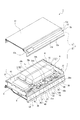
車載用バッテリー1は収納ケース2と電池モジュール3、3、・・・を有している(図5乃至図7参照)。
The on-
収納ケース2は上方に開口された箱状の収納部4と収納部4の開口を閉塞する蓋部5とを有している。
The
収納部4は前後方向を向く前面パネル6と前面パネル6の後側に位置され前後方向を向く後面パネル7と左右に離隔して位置された側面パネル8、8と上下方向を向く底面パネル9とを有している。前面パネル6と後面パネル7と側面パネル8、8と底面パネル9は何れも、例えば、アルミニウム等の押出成形によって形成されている。
The
前面パネル6と後面パネル7と側面パネル8、8と底面パネル9は何れも中空断面の形状を有している(図8参照)。前面パネル6と後面パネル7と側面パネル8、8と底面パネル9は、例えば、前後方向、左右方向又は上下方向を向く平板部10と角筒状に形成された中空部11とを有している。中空部11が中空断面の形状に形成され、中空部11は左右方向又は前後方向において貫通された状態にされている。
The
尚、前面パネル6と後面パネル7と側面パネル8、8と底面パネル9は、例えば、複数の中空部11、11、・・・が連続して設けられた形状に形成されていてもよい(図9参照)。
The
上記したように、前面パネル6と後面パネル7と側面パネル8、8と底面パネル9は何れも中空部11を有し少なくとも一部の断面形状が角筒状にされているため、高い剛性が確保されている。従って、高い剛性が確保された前面パネル6と後面パネル7と側面パネル8、8と底面パネル9によって構成された収納ケース2の収納部4は、全体としての強度が高くされている。
As described above, the
底面パネル9は前端部が他の部分より一段高い位置にある上段部9aとして設けられている(図7参照)。底面パネル9は、上段部9aに連続する後側の部分が略前後方向を向く段差部9bとして設けられ、段差部9bに連続する後側の部分が下段部9cとして設けられている。
The
蓋部5は上下方向を向く略平板状の第1の閉塞板12と収納ケース2の開口における前端部を閉塞する第2の閉塞板13とを有している(図5乃至図7参照)。蓋部5は第1の閉塞板12と第2の閉塞板13が前面パネル6等と同様に、押出成形によって平板部と角筒状に形成された中空部とを有する形状又は中空部が連続して設けられた形状に形成されていてもよい。
The
第1の閉塞板12は収納部4の開口における前端部以外の部分を上方から閉塞し、第2の閉塞板13は収納部4の開口における前端部を閉塞する。第2の閉塞板13は前後方向を向く上側垂直部13aと上側垂直部13aの下端部から前方に突出された水平部13bと水平部13bの前端部から前斜め下方に突出された傾斜部13cと傾斜部13cの下端部から下方に突出され前後方向を向く下側垂直部13dとを有している。第2の閉塞板13は上端部が第1の閉塞板12の前端部に結合され下端部が前面パネル6の上端部に結合されている。
The
第2の閉塞板13の右端寄りの位置には上下に貫通された開口部13eが形成されている。
At the position near the right end of the
第2の閉塞板13の上側垂直部13aと水平部13bによって、荷室300に前方、上方、左方及び右方に開口された配置用空間14が形成されている(図3及び図7参照)。配置用空間14には耐衝撃バー109の左右両端部を除く部分が配置されている。
The upper
電池モジュール3、3、・・・は、例えば、五つが前後上下に並んで収納ケース2に収納されている。電池モジュール3、3、・・・としては、最も前側に位置された第1の電池モジュール3Aと第1の電池モジュール3Aの後側に位置された第2の電池モジュール3Bと第2の電池モジュール3Bの後側に位置された第3の電池モジュール3Cと第1の電池モジュール3Aの後側に位置され第2の電池モジュール3Bの真上に位置された第4の電池モジュール3Dと第4の電池モジュール3Dの後側に位置され第3の電池モジュール3Cの真上に位置された第5の電池モジュール3Eとが設けられている。
For example, five
第1の電池モジュール3Aと第2の電池モジュール3Bと第3の電池モジュール3Cと第4の電池モジュール3Dと第5の電池モジュール3Eは後述する電線によって直列に接続されている。
The
電池モジュール3はケース体15とケース体15の内部に収容された複数の電池セル16、16、・・・とを有している(図10参照)。
The
ケース体15は上方に開口された横長の箱状に形成されている。ケース体15には、前面部に前後に貫通された放出孔15aが形成され、後面部に前後に貫通された取入孔15bが形成されている。
The
電池セル16、16、・・・は、例えば、厚み方向が左右方向とされる向きで左右に等間隔に並んだ状態でケース体15の内部において保持されている。電池セル16、16、・・・がケース体15に保持された状態においては、電池セル16、16、・・・間にそれぞれ一定の隙間が形成される。電池セル16、16、・・・は直列に接続されている。
The
ケース体15には左右に延びる排煙管17が取り付けられている。排煙管17は上下方向を向くベース板部17aとベース板部17aの上面に位置された筒状部17bとを有している。筒状部17bはベース板部17aの前後方向における中央部に位置されている。排煙管17はベース板部17aがケース体15の上側の開口を閉塞する状態でケース体15に取り付けられている。
A
排煙管17の下面には図示しないガス流動孔が左右に等間隔に並んで形成されている。排煙管17はガス流動孔がそれぞれ電池セル16、16、・・・の真上に位置される。
Gas flow holes (not shown) are formed on the lower surface of the
排煙管17におけるベース板部17aの前後両端部にはそれぞれ横長の形状に形成された基板18、18が取り付けられている。基板18、18にはそれぞれ後述する電線が接続され、電線及び基板18、18を介して電池セル16、16、・・・に対する電気的な制御等が行われる。
At the front and rear end portions of the
電池セル16、16、・・・にはそれぞれ内部に連通可能な図示しない弁が設けられ、各弁がそれぞれ排煙管17のガス流動孔に連通されている。電池セル16において、万が一、異常が発生したときには内部でガスが発生する場合があるが、ガスが発生すると電池セル16の内圧が上昇して弁が開放され、発生したガスが弁からガス流動孔を介して排煙管17に流動される。
The
電池モジュール3、3、・・・はそれぞれ収納ケース2の内部における所定の位置に配置されている(図7参照)。第2の電池モジュール3Bと第3の電池モジュール3Cは下段に配置され、第4の電池モジュール3Dと第5の電池モジュール3Eは上段に配置され、第1の電池モジュール3Aは第2の電池モジュール3B、第3の電池モジュール3C、第4の電池モジュール3D、第5の電池モジュール3Eに対して中段に配置されている。
The
電池モジュール3、3、・・・の駆動時には、電池モジュール3、3、・・・の内部に第1の吸気ユニット19と第2の吸気ユニット20によってそれぞれ冷却風が取り込まれる(図6及び図7参照)。
At the time of driving the
第1の吸気ユニット19は第1の吸気用ダクト21と第1の吸気用ファン22と第1の吸気管23と第1のジョイントダクト24、24、24を有している。
The
第1の吸気用ダクト21は第1の電池モジュール3Aと第2の電池モジュール3Bと第3の電池モジュール3Cの内部に冷却風を取り込む機能を有している。第1の吸気用ダクト21は下端部が左右方向において三つに分岐され、分岐された部分がそれぞれ収納ケース2の内部に配置された第1のジョイントダクト24、24、24及びケース体15、15、15の後面部にそれぞれ形成された取入孔15b、15b、15bを介して第1の電池モジュール3Aと第2の電池モジュール3Bと第3の電池モジュール3Cの内部に連通されている。
The
第1の吸気用ファン22は第1の吸気用ダクト21の上端部に連結されている。
The
第1の吸気管23は下端部が第1の吸気用ファン22に連結されている。従って、第1の吸気用ファン22が回転されると、第1の吸気管23から冷却風が取り込まれ、取り込まれた冷却風が第1の吸気用ダクト21へ向けて流動される。
The lower end portion of the
第2の吸気ユニット20は第2の吸気用ダクト25と第2の吸気用ファン26と第2の吸気管27と第2のジョイントダクト28、28を有している。
The
第2の吸気用ダクト25は第4の電池モジュール3Dと第5の電池モジュール3Eの内部に冷却風を取り込む機能を有している。第2の吸気用ダクト25は下端部が左右方向において二つに分岐され、分岐された部分がそれぞれ収納ケース2の内部に配置された第2のジョイントダクト28、28及びケース体15、15の後面部にそれぞれ形成された取入孔15a、15aを介して第4の電池モジュール3Dと第5の電池モジュール3Eの内部に連通されている。
The
第2の吸気用ファン26は第2の吸気用ダクト25の上端部に連結されている。
The
第2の吸気管27は下端部が第2の吸気用ファン26に連結されている。従って、第2の吸気用ファン26が回転されると、第2の吸気管27から冷却風が取り込まれ、取り込まれた冷却風が第2の吸気用ダクト25へ向けて流動される。
The lower end portion of the
第1の吸気用ファン22と第2の吸気用ファン26が回転されると、それぞれ第1の吸気管23と第2の吸気管27から収納ケース2の外部に存在する空気が冷却風として第1の吸気用ダクト21と第2の吸気用ダクト25に取り込まれる。
When the
第1の吸気用ダクト21に取り込まれた冷却風は第1のジョイントダクト24、24、24を流動され、ケース体15、15、15の取入孔15b、15b、15bからそれぞれ第1の電池モジュール3Aと第2の電池モジュール3Bと第3の電池モジュール3Cの内部に吐出される。
The cooling air taken into the
第1の電池モジュール3Aと第2の電池モジュール3Bと第3の電池モジュール3Cの内部に吐出された冷却風は電池セル16、16、・・・間に形成された隙間を通って前方へ向かい、冷却風によって電池セル16、16、・・・の冷却が行われる。電池セル16、16、・・・間に形成された隙間を通って前方へ向かった冷却風はケース体15、15、15の放出孔15a、15a、15aからそれぞれ収納ケース2の内部空間に排出される。
The cooling air discharged into the
一方、第2の吸気用ダクト25に取り込まれた冷却風は第2のジョイントダクト28、28を流動され、ケース体15、15の取入孔15b、15bからそれぞれ第4の電池モジュール3Dと第5の電池モジュール3Eの内部に吐出される。
On the other hand, the cooling air taken into the
第4の電池モジュール3Dと第5の電池モジュール3Eの内部に吐出された冷却風は電池セル16、16、・・・間に形成された隙間を通って前方へ向かい、冷却風によって電池セル16、16、・・・の冷却が行われる。電池セル16、16、・・・間に形成された隙間を通って前方へ向かった冷却風はケース体15、15の放出孔15a、15aからそれぞれ収納ケース2の内部空間に排出される(図7に示す矢印参照)。
The cooling air discharged to the inside of the
電池モジュール3、3、・・・の左方には排煙ダクト29が配置されている(図6参照)。排煙ダクト29は電池モジュール3、3、・・・の上側に配置された排煙管17、17、・・・に連結されている。
A
電池セル16、16、・・・において異常が発生したときのガスは、排煙管17、17、・・・から排煙ダクト29を通って収納ケース2の外部に排出される。
The gas when an abnormality occurs in the
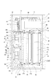
収納ケース2の内部には収納ケース2を補強する第1の補強バー30と第2の補強バー31が配置されている(図6及び図11参照)。第1の補強バー30と第2の補強バー31は何れも剛性の高い金属材料によって形成されている。
A first reinforcing
第1の補強バー30は前後方向に延びる角筒状に形成され、前端部が前面パネル6の上端部に結合され後端部が後面パネル7の上端部に結合されている。
The first reinforcing
第2の補強バー31は左右方向に延びる角筒状に形成され、左右両端部がそれぞれ側面パネル8、8の上端部に結合されている。第2の補強バー31は第1の補強バー30の直ぐ上側又は直ぐ下側に位置され第1の補強バー30と交差した状態で配置されている。
The second reinforcing
収納ケース2の内部には第1の補強バー30と第2の補強バー31によって区切られた第1の空間32、第2の空間33、第3の空間34及び第4の空間35の四つの空間が形成されている。第1の空間32は左前側に位置され、第2の空間33は第1の空間32の後側に位置され、第3の空間34は前側において第1の空間32の右側に位置され、第4の空間35は第3の空間34の後側に位置されている。
In the
第1の空間32には、下側に第1の電池モジュール3Aが配置され、上側に電池モジュール3、3、・・・等を制御する制御機器として機能する第1のジャンクションボックス36と第2のジャンクションボックス37が配置されている。第1のジャンクションボックス36と第2のジャンクションボックス37は左右に並んで配置され、第1の電池モジュール3Aの上側で第4の電池モジュール3Dの前側に位置されている。
In the
第1のジャンクションボックス36は第1のブラケット38によって保持され、第1のブラケット38は第1のジャンクションボックス36を保持する保持部38aと保持部38aの上端部から前方又は後方に突出された被取付突部38b、38b、・・・とを有している。第1のブラケット38は被取付突部38b、38b、・・・がネジ止め等によって前面パネル6の上面と第2の補強バー31の上面とに取り付けられている。従って、第1のジャンクションボックス36は第1のブラケット38を介して前面パネル6と第2の補強バー31に取り付けられている。
The
第2のジャンクションボックス37は第2のブラケット39によって保持され、第2のブラケット39は第2のジャンクションボックス37を保持する保持部39aと保持部39aの上端部から前方又は後方に突出された被取付突部39b、39b、・・・とを有している。第2のブラケット39は被取付突部39b、39b、・・・がネジ止め等によって前面パネル6の上面と第2の補強バー31の上面とに取り付けられている。従って、第2のジャンクションボックス37は第2のブラケット39を介して前面パネル6と第2の補強バー31に取り付けられている。
The
このように制御機器として機能する第1のジャンクションボックス36と第2のジャンクションボックス37がそれぞれ第1のブラケット38と第2のブラケット39を介して収納ケース2の一部として機能する前面パネル6に取り付けられている。
Thus, the
従って、収納ケース2の一部として機能する前面パネル6が第1のジャンクションボックス36と第2のジャンクションボックス37を取り付けるための取付部材としても機能し、収納ケース2の機能性の向上及び車載用バッテリー1の部品点数の削減による小型化及び軽量化を図ることができる。
Therefore, the
また、制御機器として機能する第1のジャンクションボックス36と第2のジャンクションボックス37がそれぞれ第1のブラケット38と第2のブラケット39を介して収納ケース2を補強する第2の補強バー31に取り付けられている。
In addition, the
従って、収納ケース2を補強する第2の補強バー31が第1のジャンクションボックス36と第2のジャンクションボックス37を取り付けるための取付部材としても機能し、第2の補強バー31の機能性の向上及び車載用バッテリー1の部品点数の削減による小型化及び軽量化を図ることができる。
Therefore, the second reinforcing
さらに、制御機器として機能する第1のジャンクションボックス36と第2のジャンクションボックス37がそれぞれ第1のブラケット38と第2のブラケット39を介して収納ケース2の一部として機能する前面パネル6及び収納ケース2を補強する第2の補強バー31に取り付けられている。
Furthermore, the
従って、収納ケース2の一部として機能する前面パネル6及び収納ケース2を補強する第2の補強バー31が何れも第1のジャンクションボックス36と第2のジャンクションボックス37を取り付けるための取付部材としても機能し、前面パネル6及び第2の補強バー31の機能性の向上及び車載用バッテリー1の部品点数の削減による小型化及び軽量化を図ることができる。
Therefore, the
尚、上記には、第1のジャンクションボックス36と第2のジャンクションボックス37がそれぞれ第1のブラケット38と第2のブラケット39を介して第2の補強バー31に取り付けられた例を示したが、第1の補強バー30が第1のジャンクションボックス36と第2のジャンクションボックス37を取り付けるための取付部材として機能する構成にされていてもよい。
In the example described above, the
第1のジャンクションボックス36と第2のジャンクションボックス37はそれぞれ電流等の制御を行う制御部品40、40、・・・を有し、制御部品40、40・・・としては、例えば、リレーやヒューズやコネクター端子等が設けられている。第1のジャンクションボックス36と第2のジャンクションボックス37は図示しない導電線によって車両の床下に搭載された図示しない電源回路(インバーター)に接続されている。
The
上記のように、第1のジャンクションボックス36と第2のジャンクションボックス37はそれぞれ第1のブラケット38と第2のブラケット39を介して前面パネル6の上面と第2の補強バー31の上面とに取り付けられており、収納ケース2の内部には第1のジャンクションボックス36と第2のジャンクションボックス37の下側に空間41が形成されている(図3及び図7参照)。空間41には後述する各種の電線や第1の電池モジュール3A等が配置され、空間41が収納ケース2の内部に配置される各部、例えば、電線等の配置スペースとして用いられている。
As described above, the
このように第1のジャンクションボックス36と第2のジャンクションボックス37の下側に空間41が形成されることにより、空間41が収納ケース2の内部に配置される各部の配置スペースとして用いられるため、スペースの有効活用による小型化を図ることができる。
Since the
第1の空間32には、第1のジョイントダクト24、24、24及び第2のジョイントダクト28、28から吐出され電池モジュール3、3、・・・の電池セル16、16、・・・を冷却した冷却風が流入され、この冷却風によって第1のジャンクションボックス36及び第2のジャンクションボックス37が冷却される。
Of the
上記したように、第1のジャンクションボックス36と第2のジャンクションボックス37は第1の空間32に配置されているため、中空部11を有する前面パネル6と中空部11を有する側面パネル8と第1の補強バー30と第2の補強バー31とによって前後左右から囲まれている。
As described above, since the
これにより、第1のジャンクションボックス36と第2のジャンクションボックス37の前後左右に前面パネル6と側面パネル8と第1の補強バー30と第2の補強バー31が位置され、第1のジャンクションボックス36と第2のジャンクションボックス37が前面パネル6と側面パネル8と第1の補強バー30と第2の補強バー31によって前後方向及び左右方向において保護される。
Thereby, the
従って、第1のジャンクションボックス36と第2のジャンクションボックス37の保護状態の向上を図ることができる。
Therefore, the protection state of the
また、第1の補強バー30と第2の補強バー31が中空断面を有する筒状に形成されているため、第1の補強バー30と第2の補強バー31の高い剛性が確保され、第1のジャンクションボックス36と第2のジャンクションボックス37に対する保護機能の一層の向上を図ることができる。
In addition, since the first reinforcing
さらに、第1の補強バー30が前後に延びる状態で配置されて両端部が前面パネル6と後面パネル7に連結され、第2の補強バー31が左右に延びる状態で配置されて両端部が側面パネル8、8に連結されいる。
Furthermore, the first reinforcing
従って、第1の補強バー30と第2の補強バー31によって収納ケース2の前後方向及び左右方向における耐衝撃性が高くなり、第1のジャンクションボックス36と第2のジャンクションボックス37に対する保護機能のより一層の向上を図ることができる。
Therefore, the
さらにまた、第1の補強バー30と第2の補強バー31が上下方向において交差された状態で配置されている。
Furthermore, the first reinforcing
従って、第1の補強バー30と第2の補強バー31が互いに干渉することなく収納ケース2の内部に配置され、収納ケース2の内部スペースを有効利用した上で第1のジャンクションボックス36と第2のジャンクションボックス37に対する保護機能の向上を図ることができる。
Accordingly, the first reinforcing
加えて、第1のジャンクションボックス36と第2のジャンクションボックス37が収納ケース2の内部における前端部に配置されている。
In addition, a
従って、第1のジャンクションボックス36と第2のジャンクションボックス37が車両の後端部から前方に離隔した位置に配置され、車両に対する後方からの衝突時における第1のジャンクションボックス36と第2のジャンクションボックス37に対する保護機能の向上を図ることができる。
Therefore, the
第2の空間33には、下側に第2の電池モジュール3Bと第3の電池モジュール3Cが前後に並んで配置され、上側に第4の電池モジュール3Dと第5の電池モジュール3Eが前後に並んで配置されている(図3及び図7参照)。
In the
第2の電池モジュール3Bと第3の電池モジュール3Cは底面パネル9に取り付けられている。第4の電池モジュール3Dと第5の電池モジュール3Eはそれぞれ左端部が一方の側面パネル8に取り付けられ右端部が第1の補強バー30の上面に取り付けられている(図5、図6及び図11参照)。
The
このように第4の電池モジュール3Dと第5の電池モジュール3Eが収納ケース2を補強する第1の補強バー30に取り付けられている。
Thus, the
従って、収納ケース2を補強する第1の補強バー30が第4の電池モジュール3Dと第5の電池モジュール3Eを取り付けるための取付部材としても機能し、第1の補強バー30の機能性の向上及び車載用バッテリー1の部品点数の削減による小型化及び軽量化を図ることができる。
Therefore, the first reinforcing
尚、上記には、第4の電池モジュール3Dと第5の電池モジュール3Eが第1の補強バー30に取り付けられた例を示したが、第2の補強バー31が第4の電池モジュール3Dと第5の電池モジュール3Eを取り付けるための取付部材として機能する構成にされていてもよい。
Although the example in which the
また、第1の電池モジュール3Aと第2の電池モジュール3Bと第3の電池モジュール3Cと第4の電池モジュール3Dと第5の電池モジュール3Eの少なくとも一つが第1の補強バー30又は第2の補強バー31に取り付けられた構成にされていてもよい。
In addition, at least one of the
第3の空間34における上端側の位置にはサービスプラグ42が配置されている。サービスプラグ42は収納ケース2における収納部4の開口が蓋部5に閉塞された状態において、第2の閉塞板13に形成された開口部13eに配置される(図4及び図5参照)。従って、車載用バッテリー1にあっては、収納部4の開口が蓋部5に閉塞された状態において、サービスプラグ42に対して開口部13eを介してサービスプラグ42に対する作業(引抜作業と接続作業)を行うことが可能にされている。
A
サービスプラグ42は、例えば、車両の点検整備や車両に対する衝突時における作業者等の感電を防止するために高電圧回路の遮断又は接続を行う機能を有している。サービスプラグ42は車両の点検整備や車両に対する衝突時において引き抜かれて取り出され、サービスプラグ42が取り出されることにより高電圧回路が遮断されて作業者等の感電が防止される。
The service plug 42 has a function of interrupting or connecting a high voltage circuit, for example, in order to prevent an electric shock of a worker or the like at the time of a vehicle inspection and maintenance or a collision with the vehicle. The service plug 42 is pulled out and taken out at the time of inspection and maintenance of the vehicle or a collision with the vehicle, and the high voltage circuit is interrupted by taking out the
第4の空間35には図示しない補助機器とコントロールユニット43が上下に並んで配置されている(図5、図6及び図11参照)。補助機器は夜間等の車両の非走行時における充電を行うための機器であり、コントロールユニット43は車載用バッテリー1の全体を制御するユニットである。
An auxiliary device (not shown) and a
電池セル16、16、・・・を冷却した冷却風は第4の空間35にも流入され、この冷却風によって補助機器及びコントロールユニット43が冷却される。
The cooling air that has cooled the
収納ケース2の内部には各種の電線44、44、・・・が配置されている。電線44、44、・・・は、例えば、電池モジュール3とコントロールユニット43の接続、電池モジュール3、3、・・・同士の接続、補助機器と電池モジュール3、3、・・・の接続、第1のジャンクションボックス36及び第2のジャンクションボックス37とサービスプラグ42の接続、サービスプラグ42と補助機器の接続等に用いられている。
Various kinds of
上記のように構成された車載用バッテリー1は、一部がリアフロアーパネル107の凹部107aに挿入された状態で荷室300に配置されて固定される(図3参照)。このとき第1のジャンクションボックス36と第2のジャンクションボックス37の真上に両端部がホイールエプロン108、108に結合された耐衝撃バー109が位置される。
The in-
従って、耐衝撃バー109によって車両の左右方向における耐衝撃性が高くなり、車両に対する側方からの衝突時における第1のジャンクションボックス36と第2のジャンクションボックス37に対する保護機能の向上を図ることができる。
Therefore, the impact resistance in the left-right direction of the vehicle can be enhanced by the impact
また、耐衝撃バー109が中空断面を有する角筒状に形成されているため、耐衝撃バー109の剛性が高く、第1のジャンクションボックス36と第2のジャンクションボックス37に対する保護機能の一層の向上を図ることができる。
Further, since the impact
さらに、車載用バッテリー1は車体の下部構造の一部として設けられサスペンション104、104等を支持するサブフレーム103の上方に位置されている。
Furthermore, the on-
従って、サブフレーム103によって車両の左右方向における耐衝撃性が一層高くされており、車両に対する側方からの衝突時における第1のジャンクションボックス36と第2のジャンクションボックス37に対する保護機能のより一層の向上を図ることができる。
Therefore, the impact resistance in the left-right direction of the vehicle is further enhanced by the
尚、上記には、制御機器として機能する第1のジャンクションボックス36と第2のジャンクションボックス37が前面パネル6と側面パネル8と第1の補強バー30と第2の補強バー31によって保護された例を示したが、保護される制御機器は第1のジャンクションボックス36と第2のジャンクションボックス37に限られることはない。
In the above, the
例えば、制御機器として機能する補助機器やコントロールユニット43等が収納ケース2の各一部と第1の補強バー30と第2の補強バー31によって囲まれて保護されるように構成されていてもよい。
For example, even if the auxiliary device functioning as a control device, the
また、上記には、五つの電池モジュール3、3、・・・が配置された例を示したが、収納ケース2の内部に配置される電池モジュール3の数は任意であり、四つ以下又は六つ以上の電池モジュール3が収納ケース2の内部に配置されていてもよい。
Moreover, although the example in which five
100…車体、103…サブフレーム、104…サスペンション、109…耐衝撃バー、1…車載用バッテリー、2…収納ケース、3…電池モジュール、3A…第1の電池モジュール、3B…第2の電池モジュール、3C…第3の電池モジュール、3D…第4の電池モジュール、3E…第5の電池モジュール、6…前面パネル、7…後面パネル、8…側面パネル、9…底面パネル、16…電池セル、30…第1の補強バー、31…第2の補強バー、36…第1のジャンクションボックス、37…第2のジャンクションボックス、38…第1のブラケット、39…第2のブラケット、41…空間
DESCRIPTION OF
Claims (11)
内部に複数の電池セルが配置され前記収納ケースに収納された電池モジュールと、
前記収納ケースに収納され前記電池モジュールを制御する制御機器と、
前記収納ケースの内部に配置され両端部がそれぞれ二つの前記パネルに結合された二つの補強バーとを備え、
一方の補強バーが前後に延びる状態で配置され、
他方の補強バーが左右に延びる状態で配置され、
前記制御機器が二つの前記補強バーと二つの前記パネルとによって前後左右から囲まれる位置に配置され、
前記二つの補強バーが上下方向において交差された状態で配置された
車載用バッテリー。 A storage case having a hollow cross section and formed by combining a plurality of panels;
A battery module in which a plurality of battery cells are disposed inside and stored in the storage case;
A control device which is accommodated in the accommodation case and controls the battery module;
And two reinforcing bars disposed inside the storage case and having both ends coupled to the two panels, respectively.
One reinforcement bar is arranged to extend back and forth,
The other reinforcement bar is arranged to extend left and right,
The control device is disposed at a position surrounded by the two reinforcing bars and the two panels from the front, rear, left and right,
An on- vehicle battery in which the two reinforcing bars are vertically crossed .
請求項1に記載の車載用バッテリー。 The on-vehicle battery according to claim 1, wherein the reinforcing bar is formed in a tubular shape having a hollow cross section.
請求項1又は請求項2に記載の車載用バッテリー。 The on-vehicle battery according to claim 1, wherein the control device is disposed at a front end portion inside the storage case.
内部に複数の電池セルが配置され前記収納ケースに収納された電池モジュールと、
前記収納ケースに収納され前記電池モジュールを制御する制御機器と、
前記収納ケースの内部に配置され両端部がそれぞれ二つの前記パネルに結合された少なくとも一つの補強バーとを備え、
前記制御機器が少なくとも一つの前記パネルと少なくとも一つの前記補強バーとによって前後左右から囲まれる位置に配置され、
左右に延び両端部が車体に結合された耐衝撃バーが前記制御機器の真上に位置された
車載用バッテリー。 A storage case having a hollow cross section and formed by combining a plurality of panels;
A battery module in which a plurality of battery cells are disposed inside and stored in the storage case;
A control device which is accommodated in the accommodation case and controls the battery module;
And at least one reinforcing bar disposed inside the storage case and having both ends coupled to the two panels, respectively.
The control device is disposed at a position surrounded by the at least one panel and the at least one reinforcing bar from the front, rear, left, and right .
An on- vehicle battery in which an impact resistant bar extending right and left and coupled to a vehicle body is positioned directly above the control device .
請求項4に記載の車載用バッテリー。 The on-vehicle battery according to claim 4, wherein the impact resistant bar is formed in a tubular shape having a hollow cross section.
前記制御機器が前記ブラケットを介して前記パネルに取り付けられた
請求項1乃至請求項5の何れかに記載の車載用バッテリー。 A bracket for holding the control device is provided;
The on-vehicle battery according to any one of claims 1 to 5, wherein the control device is attached to the panel via the bracket.
前記制御機器が前記ブラケットを介して前記補強バーに取り付けられた
請求項1乃至請求項5の何れかに記載の車載用バッテリー。 A bracket for holding the control device is provided;
The on-vehicle battery according to any one of claims 1 to 5, wherein the control device is attached to the reinforcing bar via the bracket.
前記制御機器が前記ブラケットを介して前記パネルと前記補強バーに取り付けられた
請求項1乃至請求項5の何れかに記載の車載用バッテリー。 A bracket for holding the control device is provided;
The on-vehicle battery according to any one of claims 1 to 5, wherein the control device is attached to the panel and the reinforcing bar via the bracket.
請求項6乃至請求項8の何れかに記載の車載用バッテリー。 The vehicle battery according to any one of claims 6 to 8, wherein a space is formed below the control device inside the storage case.
請求項1乃至請求項9の何れかに記載の車載用バッテリー。 The vehicle battery according to any one of claims 1 to 9, wherein at least a part of the battery module is attached to the reinforcing bar.
内部に複数の電池セルが配置され前記収納ケースに収納された電池モジュールと、
前記収納ケースに収納され前記電池モジュールを制御する制御機器と、
前記収納ケースの内部に配置され両端部がそれぞれ二つの前記パネルに結合された少なくとも一つの補強バーとを備え、
前記制御機器が少なくとも一つの前記パネルと少なくとも一つの前記補強バーとによって前後左右から囲まれる位置に配置され、
前記制御機器が、車体の下部構造の一部として設けられ少なくともサスペンションを支持するサブフレームの上方に位置された
車載用バッテリー。 A storage case having a hollow cross section and formed by combining a plurality of panels;
A battery module in which a plurality of battery cells are disposed inside and stored in the storage case;
A control device which is accommodated in the accommodation case and controls the battery module;
And at least one reinforcing bar disposed inside the storage case and having both ends coupled to the two panels, respectively.
The control device is disposed at a position surrounded by the at least one panel and the at least one reinforcing bar from the front, rear, left, and right .
An on- vehicle battery , wherein the control device is provided as a part of a lower structure of a vehicle body and located above a sub-frame which supports at least a suspension .
Priority Applications (1)
| Application Number | Priority Date | Filing Date | Title |
|---|---|---|---|
| JP2015062491A JP6525657B2 (en) | 2015-03-25 | 2015-03-25 | Automotive battery |
Applications Claiming Priority (1)
| Application Number | Priority Date | Filing Date | Title |
|---|---|---|---|
| JP2015062491A JP6525657B2 (en) | 2015-03-25 | 2015-03-25 | Automotive battery |
Publications (2)
| Publication Number | Publication Date |
|---|---|
| JP2016179798A JP2016179798A (en) | 2016-10-13 |
| JP6525657B2 true JP6525657B2 (en) | 2019-06-05 |
Family
ID=57131439
Family Applications (1)
| Application Number | Title | Priority Date | Filing Date |
|---|---|---|---|
| JP2015062491A Active JP6525657B2 (en) | 2015-03-25 | 2015-03-25 | Automotive battery |
Country Status (1)
| Country | Link |
|---|---|
| JP (1) | JP6525657B2 (en) |
Families Citing this family (2)
| Publication number | Priority date | Publication date | Assignee | Title |
|---|---|---|---|---|
| JP6629515B2 (en) * | 2015-03-25 | 2020-01-15 | 株式会社Subaru | Automotive battery |
| JP7061522B2 (en) * | 2018-06-27 | 2022-04-28 | 本田技研工業株式会社 | Battery pack and electric vehicle |
Family Cites Families (8)
| Publication number | Priority date | Publication date | Assignee | Title |
|---|---|---|---|---|
| JPH0752658A (en) * | 1993-08-16 | 1995-02-28 | Nissan Motor Co Ltd | Structure for holding battery of electric vehicle in place |
| JP4118130B2 (en) * | 2002-11-28 | 2008-07-16 | トヨタ自動車株式会社 | Electric car |
| JP4065809B2 (en) * | 2003-05-21 | 2008-03-26 | 本田技研工業株式会社 | In-vehicle structure of high-voltage equipment components |
| EP2425998B1 (en) * | 2009-04-27 | 2014-12-31 | Toyota Jidosha Kabushiki Kaisha | Power supply device mounting structure |
| JP5540902B2 (en) * | 2010-06-02 | 2014-07-02 | マツダ株式会社 | Battery mounting structure for electric vehicles |
| JP5698581B2 (en) * | 2011-03-28 | 2015-04-08 | 株式会社クリーンクラフト | Electric vehicle body floor structure |
| JP5888955B2 (en) * | 2011-12-06 | 2016-03-22 | アイシン軽金属株式会社 | Battery module mounting structure |
| JP2014193692A (en) * | 2013-03-29 | 2014-10-09 | Nissan Motor Co Ltd | Rear part structure of car body |
-
2015
- 2015-03-25 JP JP2015062491A patent/JP6525657B2/en active Active
Also Published As
| Publication number | Publication date |
|---|---|
| JP2016179798A (en) | 2016-10-13 |
Similar Documents
| Publication | Publication Date | Title |
|---|---|---|
| JP5829706B2 (en) | Automotive battery | |
| JP6181723B2 (en) | Body structure and in-vehicle battery | |
| JP6622368B2 (en) | Automotive battery | |
| JP5001982B2 (en) | Hybrid type vehicle | |
| JP5825694B2 (en) | In-vehicle structure of battery pack | |
| US7931105B2 (en) | Structure for mounting batteries onto electric vehicles | |
| JP5967477B2 (en) | Battery pack | |
| JP6011949B2 (en) | Automotive battery | |
| JP5516084B2 (en) | In-vehicle system circuit charger mounting structure | |
| JP6286458B2 (en) | vehicle | |
| CN108367660B (en) | Mounting structure of high-voltage control device unit | |
| WO2018106342A1 (en) | Motor guidance component configured to direct movement of a dislodged electric motor of an electric vehicle in response to crash forces | |
| JP2012054054A (en) | Power storage device and vehicle | |
| JP2018069809A (en) | vehicle | |
| JP2017065474A (en) | On-vehicle battery | |
| JP6607889B2 (en) | Body structure | |
| JP2009029159A (en) | Vehicle with internal combustion engine and rotating electric machine as power sources | |
| JP2007069801A (en) | Structure of power supply to be mounted on vehicle | |
| JP2009274666A (en) | Support structure for electric storage device | |
| JP2006281805A (en) | Arrangement structure of vehicular engine auxiliary machine | |
| JP2013112210A (en) | Battery mounting structure of vehicle | |
| CN112886121A (en) | Battery system for vehicle | |
| JP6525657B2 (en) | Automotive battery | |
| JP6992585B2 (en) | Vehicle undercarriage | |
| JP6629515B2 (en) | Automotive battery |
Legal Events
| Date | Code | Title | Description |
|---|---|---|---|
| A621 | Written request for application examination |
Free format text: JAPANESE INTERMEDIATE CODE: A621 Effective date: 20180209 |
|
| A977 | Report on retrieval |
Free format text: JAPANESE INTERMEDIATE CODE: A971007 Effective date: 20181207 |
|
| A131 | Notification of reasons for refusal |
Free format text: JAPANESE INTERMEDIATE CODE: A131 Effective date: 20190205 |
|
| A521 | Request for written amendment filed |
Free format text: JAPANESE INTERMEDIATE CODE: A523 Effective date: 20190326 |
|
| TRDD | Decision of grant or rejection written | ||
| A01 | Written decision to grant a patent or to grant a registration (utility model) |
Free format text: JAPANESE INTERMEDIATE CODE: A01 Effective date: 20190409 |
|
| A61 | First payment of annual fees (during grant procedure) |
Free format text: JAPANESE INTERMEDIATE CODE: A61 Effective date: 20190507 |
|
| R150 | Certificate of patent or registration of utility model |
Ref document number: 6525657 Country of ref document: JP Free format text: JAPANESE INTERMEDIATE CODE: R150 |
|
| R250 | Receipt of annual fees |
Free format text: JAPANESE INTERMEDIATE CODE: R250 |
|
| R250 | Receipt of annual fees |
Free format text: JAPANESE INTERMEDIATE CODE: R250 |
|
| R250 | Receipt of annual fees |
Free format text: JAPANESE INTERMEDIATE CODE: R250 |