EP2446813B1 - Ophthalmologisches Analysegerät - Google Patents
Ophthalmologisches Analysegerät Download PDFInfo
- Publication number
- EP2446813B1 EP2446813B1 EP11184914.7A EP11184914A EP2446813B1 EP 2446813 B1 EP2446813 B1 EP 2446813B1 EP 11184914 A EP11184914 A EP 11184914A EP 2446813 B1 EP2446813 B1 EP 2446813B1
- Authority
- EP
- European Patent Office
- Prior art keywords
- illumination
- analysis apparatus
- eye
- optical axis
- cornea
- Prior art date
- Legal status (The legal status is an assumption and is not a legal conclusion. Google has not performed a legal analysis and makes no representation as to the accuracy of the status listed.)
- Active
Links
Images



Classifications
-
- A—HUMAN NECESSITIES
- A61—MEDICAL OR VETERINARY SCIENCE; HYGIENE
- A61B—DIAGNOSIS; SURGERY; IDENTIFICATION
- A61B3/00—Apparatus for testing the eyes; Instruments for examining the eyes
- A61B3/10—Objective types, i.e. instruments for examining the eyes independent of the patients' perceptions or reactions
- A61B3/16—Objective types, i.e. instruments for examining the eyes independent of the patients' perceptions or reactions for measuring intraocular pressure, e.g. tonometers
- A61B3/165—Non-contacting tonometers
Definitions
- the invention relates to an ophthalmological analyzer for measuring an intraocular pressure in an eye, comprising an illumination system, wherein the analyzer comprises an actuating device with which an air blast for deforming a cornea can be applied to the eye, in the direction of an optical axis of the eye.
- the illumination system comprises at least one illumination device, with which the cornea of the eye can be illuminated with a light slit, such that a sectional image can be generated in an illumination plane which coincides with the optical axis.
- Such analysis systems can be designed, for example, as so-called non-contact tonometers, which can deform a cornea of an eye without contact by applying an air blast by means of an actuating device.
- the actuator may include a nozzle that is positioned approximately in the direction of a visual axis of the eye.
- To measure an intraocular pressure in the eye it is necessary to observe a deformation caused by the air blast. So it is known to record this deformation with an observation system. For example, the observation system detect a time of folding and unfolding, as well as a flat applanation of the cornea by the air blast.
- the observation system is regularly formed from a camera device, wherein during the deformation of the cornea, the eye is illuminated with an illumination system in such a way that the aforementioned deformation stages can be derived from detected light reflections of the cornea.
- Lighting systems are also known in which the eye is illuminated so that sectional images of the undeformed and the deformed cornea can be recorded by means of the camera apparatus.
- a lighting device is provided which projects a light gap on the cornea in the direction of the optical axis of the eye. An area of the cornea illuminated by the light gap becomes visible as a sectional image, which can be recorded by a camera device arranged obliquely next to the eye.
- a non-contact tonometer with an illumination system which is designed to project a target on the cornea of an eye.
- the illumination system comprises two illumination devices, each having an LED and a diaphragm, which are arranged at an angle ⁇ relative to an optical axis of an eye.
- the respective destinations of the lighting devices are punctiform or circular.
- the EP 1 779 771 A1 discloses a noncontact tonometer having an illumination system with a light source disposed at an angle ⁇ relative to an optical axis of an eye. Also, another illumination system is provided which is used to measure corneal thickness.
- the US 2005/174534 A1 describes a non-contact tonometer with a lighting system having four lighting devices. Two of the lighting devices are arranged in a common horizontal plane at an angle ⁇ relative to an optical axis of an eye. The illumination devices are used to determine a topography of a cornea.
- Another noncontact tonometer is from the US 6,053,867 known, wherein a light gap is projected by means of a lighting system on a cornea.
- the light gap penetrates the surface of the cornea and is reflected by a posterior surface of the cornea so that a thickness of the cornea can be determined.
- the thickness measurement is carried out with a line scan camera on which the reflection image of the light slit is projected.
- the US 4,834,527 describes a noncontact tonometer in kind of the DE 39 90 085 C2 with lighting devices, wherein a substantially punctiform illumination of the cornea of an eye for generating a detectable reflection mark takes place.
- EP 2 095 761 A1 An analyzer having the features of the preamble of claim 1 is known from EP 2 095 761 A1 known.
- the EP 2 095 761 A1 describes a noncontact tonometer with an illumination system having a slit aperture. About a beam splitter cube, a light slit of the illumination system in the direction and coaxial with an optical axis of the non-contact tonometer is projected onto the eye to be examined. In particular, it is provided that the light gap passes exactly through a nozzle opening of the noncontact tonometer.
- a Scheimpflug camera can also be provided for recording a sectional image of the eye.
- the present invention is therefore based on the object of proposing an ophthalmological analyzer with which a quality of illumination can be improved while more comfortable for a patient examination conditions.
- the ophthalmological analyzer for measuring an intraocular pressure in an eye, with an illumination system
- the ophthalmological analyzer has an actuating device with which an air blast for the deformation of a cornea can be applied to the eye, in the direction of an optical axis of the eye
- the illumination system comprises at least one illumination device, with which the cornea of the eye can be illuminated with a light gap, such that in a matching with the optical axis illumination plane a sectional image can be generated, wherein the illumination device is formed and arranged laterally relative to the actuating device, that an aligned on the eye illumination beam path of the illumination device is arranged at an angle ⁇ relative to the optical axis or visual axis of the eye.
- the illumination device laterally next to a nozzle of the actuating device, that nevertheless a sectional image in the eye can be generated in a region of the illumination plane lying in the visual axis, but a beam path of the illumination device is no longer hindered by the actuating device or the nozzle ,
- the light gap or the illumination beam path must lie in the illumination plane coinciding with the optical axis, so that a maximum of a deformation of the cornea can be detected at all. This is possible because the lighting plane is aligned in the direction of the air blast. A quality of the lighting and thus the sectional images can be noticeably improved by the lateral arrangement of the lighting device.
- the actuating device it becomes possible to arrange the actuating device completely in the direction of the optical axis without the need for, for example, a curved nozzle feed line. As a result, the actuator as a whole is also formed more compact.
- Another advantage of the side oblique arrangement of the lighting device is that a glare of a person to be examined is reduced because the light entering the eye is not projected directly into a central region of a retina of the eye.
- the lighting system comprises two lighting devices that can illuminate the lighting level.
- two lighting devices that can illuminate the lighting level.
- it can be ensured that no unwanted shadowing of edge regions of the cornea takes place by a lighting device alone.
- still further improved sectional images can be achieved, since due to possibly different light incidence angle of the different illumination beam paths of the illumination device improved light scattering within the optical medium of the cornea can be achieved.
- particles located on or in the cornea can be illuminated by the use of two illumination devices so that an undesired particle shadow is at least partially illuminated or eliminated.
- the use of two such lighting devices opens up the possibility of producing a sectional image in a particularly large area of the cornea.
- the illumination devices can be arranged coaxially to the optical axis. From a coaxial, and thereby relatively relative to the optical axis, opposite arrangement of the lighting devices there is the advantage that the illumination beam paths can be particularly well matched. In particular, a superimposition of the beam paths in the area of the cornea is required.
- the lighting device has a filter device which can compensate differences in brightness of a sectional image. Differences in brightness of a sectional image may arise, for example, in that, with the illumination beam path incident laterally obliquely into the cornea, a section of the illumination beam path covers a longer path through the cornea than another section. With the help of the filter device can then the part of the illumination beam path, the brighter appearing The cross-sectional image causes darkening so that the cross-sectional image appears evenly uniform overall.
- the filter device may, for example, form at least one graduated filter.
- a graduated filter it is particularly easy to achieve a darkening of a sectional image in optionally bright areas of the same.
- the gradient filter can be designed so that it can darken the illumination beam path in the middle.
- Such a gradient filter makes it possible to darken these overlap areas.
- the gradient filter can darken the illumination beam path transversely to the light gap steadily.
- a light-to-dark course of the illumination beam path can be achieved transversely to the same.
- the laterally oblique incidence of the illumination beam path into the eye can be taken into account with such a gradient filter and possible brightness deviations of the sectional image can be corrected.
- a lighting means of the lighting device can be formed from at least one light-emitting diode.
- the light-emitting diode can be arranged in conjunction with one or more lenses and / or diaphragms for forming the illumination beam path in the illumination device.
- the illumination device can also have a deflection device, such as a prism or a mirror, by means of which the illumination beam path in the illumination device is surrounded by a light beam Angle ⁇ can be deflected.
- the angle ⁇ can be for example 90 °, so that a housing of the lighting device can be arranged transversely to the illumination plane.
- the analysis device may comprise an observation system with which the deformation of the cornea can be observed and recorded, whereby the observation system can be used to take sectional images of the undeformed and deformed cornea.
- the intraocular pressure can be determined particularly accurately, since sectional images of high optical quality can be obtained by using the illumination system according to the invention. Since the sectional images are evaluated by means of the analysis device with respect to a deformation profile, consequently, the deformation profile can be determined particularly precisely.
- the lighting system is spatially independent of the actuating device, influencing of the lighting device or of the lighting system can be precluded by an optionally mechanical drive of the actuating device. Also, replacement or maintenance and calibration of the illumination system can then be performed independently of the analysis system, since the illumination system can then be exchanged particularly easily.
- a lighting device of the lighting system relative to a device axis of the actuator or the optical axis of the eye can be formed by an angle ⁇ pivotally.
- the observation system comprises a camera device with which the sectional images can be recorded, and wherein the camera device and the illumination system are arranged so that the camera device and the sectional image are arranged in a Scheimpflug arrangement according to the Scheimpflug rule. So then can be obtained by means of the camera device recordings of the sectional images, which are equalized. This allows for immediate measurement of lengths and positions from the slice images without the need for further corrective calculations.
- the actuator may comprise a transparent plate in which an opening for discharging the air blast is formed, wherein an illumination beam path of the illumination system can penetrate the plate.
- the transparent plate can surround the nozzle so far and form a nozzle opening, that a violation of the eye is prevented by pointed components.
- the illumination beam path or the illumination beam paths of the illumination system can be directed through the transparent plate to the eye.
- the analysis device may be configured such that the observation system can be rotated together with the illumination system about a device axis of the actuator or the optical axis of the eye.
- This makes it possible to obtain sectional images of the respective different angles of rotation, from which a three-dimensional model of the relevant area of the eye can be derived from the sectional images by means of the analysis device.
- compact design of the actuator facilitates the formation of such Analyzer.
- the observation system and the illumination system can rotate freely around the axis of the instrument since the actuator can be formed along the optical axis.
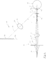
- FIG. 1 and 2 shows an illumination system 10 with a partially illustrated actuator 11 of an analysis device not shown here and an eye 12.
- an observation system 13 of the analyzer can be seen.
- the analyzer is used to measure an intraocular pressure in the eye 12, wherein the actuator 11, a puff of air for the deformation of a cornea 14 of the eye 12 is applied to the eye 12, in the direction of an optical axis 15 of the eye 12.
- the actuating device 11 is substantially composed of a piston pump 16, with a drive not shown here, and a piston 17, which is arranged longitudinally movably in a cylinder 18 and a nozzle 19.
- the nozzle 19 includes a nozzle passage 20, a nozzle port 21, and a transparent plate 22 in which the nozzle port 21 is formed.
- the actuating device 11 is arranged substantially along the optical axis 15.
- the illumination system 10 comprises two illumination devices 23 which illuminate the cornea 14 with a light gap 25 generated by a diaphragm 24 in such a way that a sectional image 27 is generated in an illumination plane 26 which coincides with the optical axis 15.
- An illumination beam path 28 or its optical axis 29 of the illumination device 23 is arranged at an angle ⁇ relative to the optical axis 15 of the eye 12.
- the illumination devices 23 each essentially comprise a light-emitting diode 30 as a light source and a lens 31 for adapting the illumination beam path 28.
- the illumination devices 23 are arranged relative to the actuating device 11 such that the respective illumination beam paths 28 fall through the transparent plate 22 into the eye 12 and superimpose each other in the area of the cornea 14 and produce the sectional image 27.
- the sectional image 27 is recorded by means of the observation system 13, which is also shown only schematically here.
- the observation system 13 is formed from a camera not shown in detail here with an image sensor 32 and a lens 33.
- the image sensor 32 forms a projection plane 34 which, together with an objective plane 35 and the illumination plane 26, are arranged as an image plane according to the Scheimpflug rule.
- an optical axis 36 of the observation system 13 is arranged at an angle ⁇ relative to the illumination plane 26, wherein the optical axis 36 lies with the optical axis 15 in a cross-sectional plane 37.
- FIG. 3 and 4 shows a lighting system 38 in various perspective views, wherein in Fig. 4 in addition, an actuating device 39 is shown.
- the illumination system 38 consists essentially of two identical illumination devices 40 with a housing 41 and a light source not shown here in detail, and a deflection device designed as a mirror 42 for deflecting an illumination beam path 43 on an eye 44.
- the illumination beam path 43 is thereby deflected at an angle of approximately 90 °.
- the illumination devices 40 are arranged relative to an optical axis 45 of the eye 44 such that an optical axis 46 of the illumination beam path 43 forms an angle ⁇ with the optical axis 45 of the eye 44, so that the actuating device 39 between the two illumination devices 40 before the Eye 44 can be arranged with a nozzle 47.
- a nozzle channel 48 of the nozzle 47 is aligned with the optical axis 45 of the eye 44th
Landscapes
- Health & Medical Sciences (AREA)
- Life Sciences & Earth Sciences (AREA)
- Engineering & Computer Science (AREA)
- Medical Informatics (AREA)
- Surgery (AREA)
- Biophysics (AREA)
- Biomedical Technology (AREA)
- Heart & Thoracic Surgery (AREA)
- Physics & Mathematics (AREA)
- Molecular Biology (AREA)
- Ophthalmology & Optometry (AREA)
- Animal Behavior & Ethology (AREA)
- General Health & Medical Sciences (AREA)
- Public Health (AREA)
- Veterinary Medicine (AREA)
- Eye Examination Apparatus (AREA)
- General Engineering & Computer Science (AREA)
Description
- Die Erfindung betrifft ein ophthalmologisches Analysegerät zur Messung eines intraokularen Drucks in einem Auge, mit einem Beleuchtungssystem, wobei das Analysegerät eine Betätigungsvorrichtung aufweist, mit der ein Luftstoß zur Verformung einer Hornhaut auf das Auge, in Richtung einer optischen Achse des Auges, aufgebracht werden kann, wobei das Beleuchtungssystem zumindest eine Beleuchtungsvorrichtung umfasst, mit der die Hornhaut des Auges mit einem Lichtspalt beleuchtet werden kann, derart, dass in einer mit der optischen Achse übereinstimmenden Beleuchtungsebene ein Schnittbild erzeugt werden kann.
- Derartige Analysesysteme können beispielsweise als sogenannte Nonkontakt-Tonometer ausgebildet sein, die eine Hornhaut eines Auges berührungsfrei durch Aufbringen eines Luftstoßes mittels einer Betätigungsvorrichtung verformen können. Die Betätigungsvorrichtung kann eine Düse umfassen, die in etwa in Richtung einer Sehachse des Auges positioniert wird. Zur Messung eines intraokularen Drucks in dem Auge ist es notwendig, eine durch den Luftstoß bewirkte Verformung zu beobachten. So ist es bekannt, diese Verformung mit einem Beobachtungssystem aufzunehmen. Das Beobachtungssystem kann beispielsweise einen Zeitpunkt eines Einklappens und eines Ausklappens, sowie eine ebene Applanation der Hornhaut durch den Luftstoß erfassen. Das Beobachtungssystem ist regelmäßig aus einer Kameravorrichtung gebildet, wobei während der Verformung der Hornhaut das Auge mit einem Beleuchtungssystem so beleuchtet wird, dass aus erfassten Lichtreflektionen der Hornhaut die vorgenannten Verformungsstadien abgeleitet werden können. Auch sind Beleuchtungssysteme bekannt, bei denen das Auge so beleuchtet wird, dass Schnittbilder der unverformten und der verformten Hornhaut mittels der Kameravorrichtung aufgenommen werden können. In diesem Fall ist eine Beleuchtungsvorrichtung vorgesehen, die in Richtung der optischen Achse des Auges einen Lichtspalt auf die Hornhaut projiziert. Ein von dem Lichtspalt beleuchteter Bereich der Hornhaut wird als ein Schnittbild sichtbar, welches von einer schräg neben dem Auge angeordneten Kameravorrichtung aufgenommen werden kann. Dabei besteht die Problematik, dass eine Beleuchtung der Hornhaut bzw. eine die Sehachse des Auges schneidende Beleuchtungsebene im Auge durch eine Position der Düse der Betätigungsvorrichtung auf der Sehachse behindert wird. Dem wird zwar dadurch entgegengetreten, dass ein Bereich um eine Düsenöffnung herum transparent ausgebildet ist, und dass der Lichtspalt durch die Düsenöffnung auf das Auge projiziert wird, jedoch stellt dies keine befriedigende Lösung dar, da der Lichtspalt nicht direkt und somit nicht störungsfrei auf das Auges projiziert werden kann. Weiter ist es notwendig die Betätigungsvorrichtung mit Ausnahme der Düse außerhalb der optischen Achse des Auges anzuordnen, was einen konstruktiv erhöhten Aufwand erfordert.
- Aus der
DE 39 90 085 C2 ist ein Nonkontakt-Tonometer mit einem Beleuchtungssystem bekannt, welches zur Projektion einer Zielmarke auf die Hornhaut eines Auges ausgebildet ist. Das Beleuchtungssystem umfasst zwei Beleuchtungsvorrichtungen mit jeweils einer LED und einer Blende, welche in einem Winkel α relativ zu einer optischen Achse eines Auges angeordnet sind. Die jeweiligen Zielmarken der Beleuchtungsvorrichtungen sind punktförmig beziehungsweise kreisförmig ausgebildet. - Die
EP 1 779 771 A1 offenbart ein Nonkontakt-Tonometer mit einem Beleuchtungssystem mit einer Lichtquelle, welche in einem Winkel α relativ zu einer optischen Achse eines Auges angeordnet ist. Auch ist ein weiteres Beleuchtungssystem vorgesehen, welches zur Messung einer Hornhautdicke verwendet wird. - Die
US 2005/174534 A1 beschreibt ein Nonkontakt-Tonometer mit einem Beleuchtungssystem, welches vier Beleuchtungsvorrichtungen aufweist. Zwei der Beleuchtungsvorrichtungen sind in einer gemeinsamen horizontalen Ebene in einem Winkel α relativ zu einer optischen Achse eines Auges angeordnet. Die Beleuchtungsvorrichtungen dienen zur Bestimmung einer Topographie einer Hornhaut. - Ein weiteres Nonkontakt-Tonometer ist aus der
US 6,053,867 bekannt, wobei ein Lichtspalt mittels eines Beleuchtungssystems auf eine Hornhaut projiziert wird. Der Lichtspalt durchdringt die Oberfläche der Hornhaut und wird von einer rückwärtigen Fläche der Hornhaut reflektiert, sodass eine Dicke der Hornhaut bestimmt werden kann. Die Dickenmessung erfolgt mit einer Zeilenkamera, auf der das Reflexionsbild des Lichtspaltes projiziert wird. - Ein aus der
US 6,120,444 bekanntes Beleuchtungssystem wird zur direkten, das heisst in der Richtung einer optischen Achse eines Auges ausgerichteten Beleuchtung der Hornhaut in Zusammenspiel mit einer Scheimflugkamera verwendet. Ein Lichtspalt wird entlang der optischen Achse auf die Hornhaut des Auges projiziert, sodass ein Schnittbild in einer mit der optischen Achse übereinstimmenden Beleuchtungsebene erzeugt werden kann. - Bei dem Nonkontakt-Tonometer der
US 5,002,056 ist ein Beleuchtungssystem quer zu einer optischen Achse angeordnet und dient zur Beobachtung einer Hornhautverformung. Im Wesentlichen wird hier ein Reflexionsbild einer hier nicht näher beschriebenen Zielmarke beobachtet. - Die
US 4,834,527 beschreibt ein Nonkontakt-Tonometer in Art dem derDE 39 90 085 C2 mit Beleuchtungsvorrichtungen, wobei eine im Wesentlichen punktförmige Beleuchtung der Hornhaut eines Auges zur Erzeugung einer detektierbaren Reflexionsmarke erfolgt. - Aus der
US 5,751,395 ist eine Beleuchtungsvorrichtung bekannt, deren Strahlengang abschnittsweise in Richtung einer optischen Achse eines Auges ausgerichtet ist. - Ein Analysegerät mit den Merkmalen des Oberbegriffs des Anspruchs 1 ist aus der
EP 2 095 761 A1 bekannt. DieEP 2 095 761 A1 beschreibt ein Nonkontakt-Tonometer mit einem Beleuchtungssystem, welches eine Spaltblende aufweist. Über einen Strahlenteilerwürfel wird ein Lichtspalt des Beleuchtungssystems in Richtung und koaxial mit einer optischen Achse des Nonkontakt-Tonometers auf das zu untersuchende Auge projiziert. Insbesondere ist dabei vorgesehen, dass der Lichtspalt genau durch eine Düsenöffnung des Nonkontakt-Tonometers verläuft. Nach einer Ausführungsform des Analysegerätes kann auch eine Scheimpflugkamera zur Aufnahme eines Schnittbildes des Auges vorgesehen sein. - Der vorliegenden Erfindung liegt daher die Aufgabe zugrunde, ein ophthalmologisches Analysegerät vorzuschlagen, mit dem eine Beleuchtungsqualität bei für einen Patienten angenehmeren Untersuchungsbedingungen verbessert werden kann.
- Diese Aufgabe wird durch ein Analysegerät mit den Merkmalen des Anspruchs 1 gelöst.
- Bei dem erfindungsgemäßen ophthalmologischen Analysegerät zur Messung eines intraokularen Drucks in einem Auge, mit einem Beleuchtungssystem, weist das ophthalmologische Analysegerät eine Betätigungsvorrichtung auf, mit der ein Luftstoß zur Verformung einer Hornhaut auf das Auge, in Richtung einer optischen Achse des Auges, aufgebracht werden kann, wobei das Beleuchtungssystem zumindest eine Beleuchtungsvorrichtung umfasst, mit der die Hornhaut des Auges mit einem Lichtspalt beleuchtet werden kann, derart, dass in einer mit der optischen Achse übereinstimmenden Beleuchtungsebene ein Schnittbild erzeugt werden kann, wobei die Beleuchtungsvorrichtung so ausgebildet und seitlich relativ zur Betätigungsvorrichtung angeordnet ist, dass ein auf das Auge ausgerichteter Beleuchtungsstrahlengang der Beleuchtungsvorrichtung in einem Winkel α relativ zur optischen Achse bzw. Sehachse des Auges angeordnet ist.
- Demnach ist vorgesehen, die Beleuchtungsvorrichtung so seitlich neben einer Düse der Betätigungsvorrichtung anzuordnen, dass dennoch in einem Bereich der in der Sehachse liegenden Beleuchtungsebene ein Schnittbild im Auge erzeugt werden kann, ein Strahlengang der Beleuchtungsvorrichtung jedoch nicht mehr von der Betätigungsvorrichtung bzw. der Düse behindert wird. Der Lichtspalt bzw. der Beleuchtungsstrahlengang muss dabei in der mit der optischen Achse übereinstimmenden Beleuchtungsebene liegen, damit ein Maximum einer Verformung der Hornhaut überhaupt erfasst werden kann. Dies wird dadurch möglich, dass die Beleuchtungsebene in Richtung des Luftstoßes ausgerichtet ist. Eine Qualität der Beleuchtung und damit der Schnittbilder kann durch die seitliche Anordnung der Beleuchtungsvorrichtung spürbar verbessert werden. Weiter wird es möglich die Betätigungsvorrichtung auch vollständig in Richtung der optischen Achse anzuordnen, ohne dass eine beispielsweise gebogene Düsenzuleitung notwendig wäre. Dadurch wird die Betätigungsvorrichtung insgesamt auch kompakter ausbildbar. Ein weiterer Vorteil der seitlich schrägen Anordnung der Beleuchtungsvorrichtung ist, dass eine Blendung einer zu untersuchenden Person gemindert wird, da dass in das Auge einfallende Licht nicht unmittelbar in einen Zentralbereich einer Netzhaut des Auges projiziert wird.
- Besonders vorteilhaft ist es, wenn das Beleuchtungssystem zwei Beleuchtungsvorrichtungen umfasst, die die Beleuchtungsebene beleuchten können. So kann sichergestellt werden, dass keine unerwünschte Abschattung von Randbereichen der Hornhaut durch alleine eine Beleuchtungsvorrichtung erfolgt. Auch können noch weiter verbesserte Schnittbilder erzielt werden, da aufgrund gegebenenfalls unterschiedlicher Lichteinfallswinkel der unterschiedlichen Beleuchtungsstrahlengänge der Beleuchtungsvorrichtung eine verbesserte Lichtstreuung innerhalb des optischen Mediums der Hornhaut erzielt werden kann. Auch können auf oder in der Hornhaut befindliche Partikel durch die Verwendung von zwei Beleuchtungsvorrichtungen so beleuchtet werden, dass ein unerwünschter Partikelschatten zumindest teilweise ausgeleuchtet bzw. eliminiert wird. Auch wird durch die Verwendung von zwei derartigen Beleuchtungsvorrichtungen die Möglichkeit eröffnet, ein Schnittbild in einem besonders großen Bereich der Hornhaut zu erzeugen.
- Weiter können die Beleuchtungsvorrichtungen koaxial zur optischen Achse angeordnet sein. Aus einer koaxialen, und dadurch relativ auf die optische Achse bezogenen, gegenüberliegenden Anordnung der Beleuchtungsvorrichtungen ergibt sich der Vorteil, dass die Beleuchtungsstrahlengänge besonders gut aufeinander abgestimmt werden können. So ist insbesondere eine Überlagerung der Strahlengänge im Bereich der Hornhaut erforderlich.
- Besonders vorteilhaft ist es, wenn die Beleuchtungsvorrichtung eine Filtereinrichtung aufweist, welche Helligkeitsunterschiede eines Schnittbildes kompensieren kann. Helligkeitsunterschiede eines Schnittbildes können beispielsweise dadurch entstehen, dass bei seitlich schräg in die Hornhaut einfallenden Beleuchtungsstrahlengang ein Abschnitt des Beleuchtungsstrahlengangs einen längeren Weg durch die Hornhaut zurücklegt, als ein anderer Abschnitt. Mit Hilfe der Filtereinrichtung kann dann der Teil des Beleuchtungsstrahlengangs, der ein heller erscheinendes Schnittbild bewirkt, so abgedunkelt werden, dass das Schnittbild insgesamt gleichmäßig hell erscheint.
- Die Filtereinrichtung kann beispielsweise zumindest einen Verlaufsfilter ausbilden. Mit einem Verlaufsfilter kann besonders einfach eine Abdunklung eines Schnittbildes in gegebenenfalls zu hell erscheinenden Bereichen desselben erzielt werden.
- Der Verlaufsfilter kann dabei so ausgebildet sein, dass er den Beleuchtungsstrahlengang mittig abdunkeln kann. Insbesondere wenn zwei Beleuchtungsvorrichtungen verwendet werden, ist es möglich, dass sich im Bereich der sich überschneidenden Beleuchtungsstrahlengänge innerhalb der Hornhaut des Auges besonders helle Bereiche in dem Schnittbild ausbilden. Ein derartiger Verlaufsfilter ermöglicht das Abdunkeln dieser Überschneidungsbereiche.
- Alternativ oder ergänzend kann der Verlaufsfilter den Beleuchtungsstrahlengang quer zum Lichtspalt stetig abdunkeln. So kann ein von Hell nach Dunkel reichender Verlauf des Beleuchtungsstrahlengangs quer zu demselben erzielt werden. Mit einem derartigen Verlaufsfilter kann insbesondere der seitlich schräge Einfall des Beleuchtungsstrahlengangs in das Auge berücksichtigt und eventuelle Helligkeitsabweichungen des Schnittbildes korrigiert werden.
- Ein Leuchtmittel der Beleuchtungsvorrichtung kann aus zumindest einer Leuchtdiode gebildet sein. Dabei kann die Leuchtdiode in Verbindung mit einer oder mehreren Linsen und/oder Blenden zur Ausbildung des Beleuchtungsstrahlengangs in der Beleuchtungsvorrichtung angeordnet sein. Weiter ist es auch denkbar, mehrere Leuchtdioden in einer Reihenanordnung zur Ausbildung des Lichtspaltes zu verwenden.
- Die Beleuchtungsvorrichtung kann auch eine Umlenkeinrichtung, wie zum Beispiel ein Prisma oder einen Spiegel, aufweisen, mittels der der Beleuchtungsstrahlengang in der Beleuchtungsvorrichtung um einen Winkel β umgelenkt werden kann. Der Winkel β kann beispielsweise 90° betragen, so dass ein Gehäuse der Beleuchtungsvorrichtung quer zur Beleuchtungsebene angeordnet werden kann. Durch die Umlenkeinrichtung wird es möglich, die Beleuchtungsvorrichtung bzw. ein Gehäuse derselben so auszubilden bzw. anzuordnen, dass das Analysegerät kompakt ausgebildet werden kann.
- Das Analysegerät kann ein Beobachtungssystem umfassen, mit dem die Verformung der Hornhaut beobachtet und aufgenommen werden kann, wobei mit dem Beobachtungssystem Schnittbilder der unverformten und verformten Hornhaut aufgenommen werden können. So wird es möglich mittels einer Analyseeinrichtung eines Analysegeräts aus den Schnittbildern der Hornhaut den intraokularen Druck abzuleiten. Der intraokulare Druck kann dabei besonders genau bestimmt werden, da durch die Verwendung des erfindungsgemäßen Beleuchtungssystems Schnittbilder hoher optischer Qualität gewonnen werden können. Da die Schnittbilder mittels der Analyseeinrichtung hinsichtlich eines Verformungsverlaufs ausgewertet werden, kann folglich der Verformungsverlauf besonders präzise ermittelt werden.
- Wenn das Beleuchtungssystem räumlich unabhängig von der Betätigungsvorrichtung ausgebildet ist, kann eine Beeinflussung der Beleuchtungsvorrichtung bzw. des Beleuchtungssystems durch einen gegebenenfalls mechanischen Antrieb der Betätigungsvorrichtung ausgeschlossen werden. Auch kann dann ein Auswechseln oder auch eine Wartung und Kalibrierung des Beleuchtungssystems unabhängig von dem Analysesystem durchgeführt werden, da das Beleuchtungssystem dann besonders einfach ausgetauscht werden kann.
- Auch kann eine Beleuchtungsvorrichtung des Beleuchtungssystems relativ zu einer Geräteachse der Betätigungsvorrichtung bzw. die optische Achse des Auges um einen Winkel α schwenkbar ausgebildet sein. So wird es möglich einen Einfallswinkel des Beleuchtungsstrahlengangs relativ zur optischen Achse in das Auge in geeigneter Weise einzustellen. Der Einfallswinkel kann dann auf bestimme Anforderungen einer Messung angepasst werden.
- Vorteilhaft ist es, wenn das Beobachtungssystem eine Kameravorrichtung umfasst, mit der die Schnittbilder aufgenommen werden können, und wobei die Kameravorrichtung und das Beleuchtungssystem so angeordnet sind, dass die Kameravorrichtung und das Schnittbild in einer Scheimpfluganordnung nach der Scheimpflugschen-Regel angeordnet sind. So können dann mittels der Kameravorrichtung Aufnahmen der Schnittbilder gewonnen werden, die entzerrt sind. Dies ermöglicht eine unmittelbare Messung von Längen und Positionen aus den Schnittbildern, ohne dass noch weitere, korrigierende Berechnungen notwendig wären.
- Um ein Auge bei einer möglichen Kollision mit der Betätigungsvorrichtung vor Verletzungen durch eine Düse der Betätigungsvorrichtung zu schützen, kann die Betätigungsvorrichtung eine transparente Platte aufweisen, in der eine Öffnung zum Ausbringen des Luftstoßes ausgebildet ist, wobei ein Beleuchtungsstrahlengang des Beleuchtungssystem die Platte durchdringen kann. So kann die transparente Platte die Düse so weit umgeben und eine Düsenöffnung ausbilden, dass eine Verletzung des Auges durch spitze Bauteile verhindert wird. Je nach Größe der Platte kann der Beleuchtungsstrahlengang bzw. die Beleuchtungsstrahlengänge des Beleuchtungssystems durch die transparente Platte hindurch auf das Auge gerichtet sein.
- Weiter kann das Analysegerät so ausgebildet sein, dass das Beobachtungssystem zusammen mit dem Beleuchtungssystem um eine Geräteachse der Betätigungsvorrichtung bzw. die optische Achse des Auges gedreht werden kann. Dadurch wird es möglich, Schnittbilder der jeweils verschiedenen Drehwinkel zu gewinnen, woraus mittels der Analyseeinrichtung ein dreidimensionales Modell des betreffenden Bereiches des Auges aus den Schnittbildern abgleitet werden kann. Insbesondere die durch das Beleuchtungssystem erst ermöglichte, kompakte Ausbildung der Betätigungsvorrichtung erleichtert die Ausbildung eines derartigen Analysegerätes. So können das Beobachtungssystem und das Beleuchtungssystem ungehindert um die Geräteachse rotieren, da die Betätigungsvorrichtung entlang der optischen Achse ausgebildet werden kann. Nachfolgend wird eine bevorzugte Ausführungsform der Erfindung unter Bezugnahme auf die beigefügten Zeichnungen näher erläutert.
- Es zeigen:
- Fig. 1
- eine schematisch Darstellung eines Analysegerätes in einer Draufsicht;
- Fig. 2
- eine schematische Darstellung des Analysegerätes in einer Seitenansicht;
- Fig. 3
- eine perspektivische Ansicht eines Beleuchtungssystems;
- Fig. 4
- eine perspektivische Ansicht des Beleuchtungssystems zusammen mit einer Betätigungsvorrichtung.
- Eine Zusammenschau der
Fig. 1 und2 zeigt ein Beleuchtungssystem 10 mit einer teilweise dargestellten Betätigungsvorrichtung 11 eines hier nicht gezeigten Analysegerätes sowie ein Auge 12. Weiter ist insbesondere inFig. 2 ein Beobachtungssystem 13 des Analysegerätes ersichtlich. Das Analysegerät dient zu einer Messung eines intraokularen Drucks in dem Auge 12, wobei mit der Betätigungsvorrichtung 11 ein Luftstoß zur Verformung einer Hornhaut 14 des Auges 12 auf das Auge 12, in Richtung einer optischen Achse 15 des Auges 12 aufgebracht wird. Die Betätigungsvorrichtung 11 ist dabei im Wesentlichen aus einer Kolbenpumpe 16, mit einem hier nicht näher dargestellten Antrieb, und einem Kolben 17, welcher längsbeweglich in einem Zylinder 18 angeordnet ist sowie einer Düse 19 ausgebildet. Die Düse 19 umfasst einen Düsenkanal 20, eine Düsenöffnung 21 und eine transparente Platte 22, in der die Düsenöffnung 21 ausgebildet ist. Die Betätigungseinrichtung 11 ist im Wesentlichen längs der optischen Achse 15 angeordnet. - Das Beleuchtungssystem 10 umfasst zwei Beleuchtungsvorrichtungen 23, die die Hornhaut 14 mit einem mit einer Blende 24 erzeugten Lichtspalt 25 so beleuchten, dass in einer mit der optischen Achse 15 übereinstimmenden Beleuchtungsebene 26 ein Schnittbild 27 erzeugt wird. Ein Beleuchtungsstrahlengang 28 bzw. dessen optische Achse 29 der Beleuchtungsvorrichtung 23 ist in einem Winkel α relativ zur optischen Achse 15 des Auges 12 angeordnet. Die Beleuchtungsvorrichtungen 23 umfassen jeweils im Wesentlichen eine Leuchtdiode 30 als eine Lichtquelle sowie eine Linse 31 zur Anpassung des Beleuchtungsstrahlengangs 28. Die Beleuchtungsvorrichtungen 23 sind so relativ zur Betätigungsvorrichtung 11 angeordnet, dass die jeweiligen Beleuchtungsstrahlengänge 28 durch die transparente Platte 22 hindurch in das Auge 12 fallen und sich im Bereich der Hornhaut 14 gegenseitig überlagern und das Schnittbild 27 erzeugen.
- Das Schnittbild 27 wird mittels des Beobachtungssystems 13 aufgenommen, welches hier auch nur schematisch dargestellt ist. Das Beobachtungssystem 13 ist aus einer hier nicht näher dargestellten Kamera mit einem Bildsensor 32 und einem Objektiv 33 gebildet. Der Bildsensor 32 bildet eine Projektionsebene 34 aus, die zusammen mit einer Objektivebene 35 und der Beleuchtungsebene 26 als eine Bildebene nach der Scheimpflugschen-Regel angeordnet sind. Im vorliegenden Beispiel ist eine optische Achse 36 des Beobachtungssystems 13 unter einem Winkel γ relativ zur Beleuchtungsebene 26 angeordnet, wobei die optische Achse 36 mit der optischen Achse 15 in einer Querschnittsebene 37 liegt.
- Eine Zusammenschau der
Fig. 3 und4 zeigt ein Beleuchtungssystem 38 in verschiedenen, perspektivischen Darstellungen, wobei inFig. 4 ergänzend eine Betätigungsvorrichtung 39 abgebildet ist. Das Beleuchtungssystem 38 besteht im Wesentlichen aus zwei identischen Beleuchtungsvorrichtungen 40 mit einem Gehäuse 41 und einer hier nicht näher ersichtlichen Lichtquelle sowie einer als Spiegel 42 ausgebildeten Umlenkeinrichtung zur Umlenkung eines Beleuchtungsstrahlengangs 43 auf ein Auge 44. Der Beleuchtungsstrahlengang 43 wird dabei in einem Winkel von ca. 90° umgelenkt. Die Beleuchtungsvorrichtungen 40 sind relativ zu einer optischen Achse 45 des Auges 44 so angeordnet, dass eine optische Achse 46 des Beleuchtungsstrahlengangs 43 einen Winkel α mit der optischen Achse 45 des Auges 44 bildet, so dass die Betätigungsvorrichtung 39 zwischen den beiden Beleuchtungsvorrichtungen 40 noch vor dem Auge 44 mit einer Düse 47 angeordnet werden kann. Ein Düsenkanal 48 der Düse 47 fluchtet dabei mit der optischen Achse 45 des Auges 44.
Claims (15)
- Ophthalmologisches Analysegerät zur Messung eines intraokularen Drucks in einem Auge, mit einem Beleuchtungssystem (10, 38), wobei das Analysegerät eine Betätigungsvorrichtung (11, 39) aufweist, mit der ein Luftstoß zur Verformung einer Hornhaut (14) auf das Auge (22) fluchtend mit der optischen Achse (15, 45) des Auges aufgebracht werden kann, wobei das Beleuchtungssystem zumindest eine Beleuchtungsvorrichtung (23, 40) umfasst, mit der die Hornhaut des Auges mit einem Lichtspalt (25) beleuchtet werden kann, derart, dass in einer mit der optischen Achse übereinstimmenden Beleuchtungsebene (26) ein Schnittbild (27) erzeugt werden kann,
dadurch gekennzeichnet,
dass die Beleuchtungsvorrichtung so ausgebildet und seitlich relativ zur Betätigungsvorrichtung angeordnet ist, dass ein auf das Auge ausgerichteter Beleuchtungsstrahlengang (28, 43) der Beleuchtungsvorrichtung in einem Winkel α relativ zur optischen Achse (15, 45) angeordnet ist. - Analysegerät nach Anspruch 1,
dadurch gekennzeichnet,
dass das Beleuchtungssystem (10, 38) zwei Beleuchtungsvorrichtungen (23, 40) umfasst, die die Beleuchtungsebene (26) beleuchten können. - Analysegerät nach Anspruch 2,
dadurch gekennzeichnet,
dass die Beleuchtungsvorrichtungen (23, 40) koaxial zur optischen Achse (15, 45) angeordnet sind. - Analysegerät nach einem der vorangehenden Ansprüche,
dadurch gekennzeichnet,
dass die Beleuchtungsvorrichtung (23, 40) eine Filtereinrichtung aufweist, welche Helligkeitsunterschiede eines Schnittbildes (27) kompensieren kann. - Analysegerät nach Anspruch 4,
dadurch gekennzeichnet,
dass die Filtereinrichtung zumindest einen Verlaufsfilter ausbildet. - Analysegerät nach Anspruch 5,
dadurch gekennzeichnet,
dass der Verlaufsfilter den Beleuchtungsstrahlengang (28, 43) mittig abdunkeln kann. - Analysegerät nach Anspruch 5 oder 6,
dadurch gekennzeichnet,
dass der Verlaufsfilter den Beleuchtungsstrahlengang (28, 43) quer zum Lichtspalt (25) stetig abdunkeln kann. - Analysegerät nach einem der vorangehenden Ansprüche,
dadurch gekennzeichnet,
dass ein Leuchtmittel der Beleuchtungsvorrichtung (23, 40) aus zumindest einer Leuchtdiode (30) gebildet ist. - Analysegerät nach einem der vorangehenden Ansprüche,
dadurch gekennzeichnet,
dass die Beleuchtungsvorrichtung (40) eine Umlenkeinrichtung (42) aufweist, mittels der der Beleuchtungsstrahlengang (43) in der Beleuchtungsvorrichtung um einen Winkel β umgelenkt werden kann. - Analysegerät nach einem der vorangehenden Ansprüche,
dadurch gekennzeichnet,
dass das Analysegerät ein Beobachtungssystem (13) umfasst, mit dem die Verformung der Hornhaut beobachtet und aufgenommen werden kann, wobei mit dem Beobachtungssystem Schnittbilder (27) der unverformten und verformten Hornhaut aufgenommen werden können. - Analysegerät nach Anspruch 10,
dadurch gekennzeichnet,
dass das Beleuchtungssystem (10, 38) räumlich unabhängig von der Betätigungsvorrichtung (11, 39) ausgebildet ist. - Analysegerät nach Anspruch 10 oder 11,
dadurch gekennzeichnet,
dass eine Beleuchtungsvorrichtung (23, 40) des Beleuchtungssystems (10, 38) relativ zu einer Geräteachse der Betätigungsvorrichtung (11, 39) bzw. die optische Achse (15, 45) um einem Winkel α schwenkbar ausgebildet ist. - Analysegerät nach einem der Ansprüche 10 bis 12,
dadurch gekennzeichnet,
dass das Beobachtungssystem (13) eine Kameravorrichtung (32, 33) umfasst, mit der die Schnittbilder (27) aufgenommen werden können, und wobei die Kameravorrichtung und das Beleuchtungssystem (10, 38) so angeordnet sind, dass die Kameravorrichtung und das Schnittbild in einer Scheimpfluganordnung angeordnet sind. - Analysegerät nach einem der Ansprüche 10 bis 13,
dadurch gekennzeichnet,
dass die Betätigungsvorrichtung (11, 39) eine transparente Platte (22) aufweist, in der eine Öffnung (21) zum Ausbringen des Luftstoßes ausgebildet ist, wobei ein Beleuchtungsstrahlengang (28, 43) des Beleuchtungssystems (10, 38) die Platte durchdringen kann. - Analysegerät nach einem der Ansprüche 10 bis 14,
dadurch gekennzeichnet,
dass das Analysegerät so ausgebildet ist, dass das Beobachtungssystem (13) zusammen mit dem Beleuchtungssystem (10, 38) um eine Geräteachse der Betätigungsvorrichtung (11, 39) bzw. die optische Achse (15, 45) gedreht werden kann.
Applications Claiming Priority (2)
| Application Number | Priority Date | Filing Date | Title |
|---|---|---|---|
| DE102010049632 | 2010-10-28 | ||
| DE102011082363.8A DE102011082363B4 (de) | 2010-10-28 | 2011-09-08 | Beleuchtungssystem, ophthalmologisches Analysegerät und Verfahren |
Publications (2)
| Publication Number | Publication Date |
|---|---|
| EP2446813A1 EP2446813A1 (de) | 2012-05-02 |
| EP2446813B1 true EP2446813B1 (de) | 2018-03-07 |
Family
ID=44799772
Family Applications (1)
| Application Number | Title | Priority Date | Filing Date |
|---|---|---|---|
| EP11184914.7A Active EP2446813B1 (de) | 2010-10-28 | 2011-10-12 | Ophthalmologisches Analysegerät |
Country Status (8)
| Country | Link |
|---|---|
| US (1) | US8529065B2 (de) |
| EP (1) | EP2446813B1 (de) |
| JP (1) | JP5864209B2 (de) |
| KR (1) | KR101396044B1 (de) |
| CN (1) | CN102525410B (de) |
| AU (1) | AU2011239330B2 (de) |
| DE (1) | DE102011082363B4 (de) |
| ES (1) | ES2669043T3 (de) |
Families Citing this family (10)
| Publication number | Priority date | Publication date | Assignee | Title |
|---|---|---|---|---|
| PL2397068T3 (pl) * | 2010-06-21 | 2020-11-16 | Oculus Optikgeräte GmbH | Analiza ciśnienia wewnątrzgałkowego |
| US8800347B2 (en) * | 2011-10-21 | 2014-08-12 | Reichert, Inc. | Tonometer calibration tool |
| CN103565407A (zh) * | 2012-07-20 | 2014-02-12 | 明达医学科技股份有限公司 | 喷气式眼压检测装置 |
| US9621771B2 (en) * | 2013-03-14 | 2017-04-11 | Pelco, Inc. | System and method for imaging utility panel elements |
| CN109414162A (zh) * | 2016-05-13 | 2019-03-01 | 洛桑联邦理工学院 | 用于倾斜照明下视网膜吸收相以及暗场成像的系统、方法和装置 |
| US10736506B2 (en) | 2018-06-14 | 2020-08-11 | Broadspot Imaging Corp | Composite image with cross-channel illumination |
| CN111281338B (zh) * | 2018-12-08 | 2022-08-26 | 广东英华投资控股有限公司 | 一种裂隙灯显微镜检查仪 |
| KR102234538B1 (ko) | 2019-09-17 | 2021-03-31 | 웰스메디텍 주식회사 | 촬영기기 결합형 휴대용 세극등 장치 |
| US20240016381A1 (en) * | 2020-11-17 | 2024-01-18 | N.M.B. Medical Applications Ltd | Device and method for non-contact measurement of an intraocular pressure |
| KR102702901B1 (ko) * | 2021-08-10 | 2024-09-05 | 충북대학교 산학협력단 | 다채널 led 조명의 균일도 측정장치 및 이를 이용한 다채널 led 조명의 균일도 측정방법 |
Citations (1)
| Publication number | Priority date | Publication date | Assignee | Title |
|---|---|---|---|---|
| EP2095761A1 (de) * | 2008-02-27 | 2009-09-02 | Nidek Co., Ltd. | Kontaktfreies Tonometer |
Family Cites Families (21)
| Publication number | Priority date | Publication date | Assignee | Title |
|---|---|---|---|---|
| JPS61321A (ja) * | 1984-06-12 | 1986-01-06 | 株式会社トプコン | 非接触式眼圧計 |
| DE164730T1 (de) * | 1984-06-12 | 1986-08-14 | Tokyo Kogaku Kikai K.K., Tokio/Tokyo | Beruehrungsloses tonometer. |
| JPH0624509B2 (ja) * | 1986-09-24 | 1994-04-06 | 株式会社トプコン | 眼科器械の作動距離整準用光学系 |
| DE3990085T1 (de) * | 1988-02-01 | 1990-01-11 | Topcon Corp | Ophthalmologisches instrument |
| JPH01195839A (ja) * | 1988-02-01 | 1989-08-07 | Topcon Corp | 眼科器械 |
| JP3013356B2 (ja) * | 1988-05-13 | 2000-02-28 | 株式会社ニデック | 前眼部撮影装置 |
| US5751395A (en) * | 1997-01-10 | 1998-05-12 | Thall; Edmond H. | Retinal diagnostic device |
| US5954646A (en) | 1997-04-02 | 1999-09-21 | Cds Technologies, L.L.C. | Tonometer probe with replaceable membrane |
| JPH10309265A (ja) * | 1997-05-12 | 1998-11-24 | Konan:Kk | 眼科撮影装置 |
| JP3862869B2 (ja) * | 1998-06-05 | 2006-12-27 | 株式会社トプコン | 非接触式眼圧計 |
| JP3386376B2 (ja) * | 1998-08-19 | 2003-03-17 | 株式会社トプコン | 非接触式眼圧計 |
| JP4104302B2 (ja) * | 2001-07-11 | 2008-06-18 | 株式会社ニデック | 前眼部断面解析装置及び前眼部断面解析プログラム |
| US6860602B2 (en) * | 2001-10-02 | 2005-03-01 | Nidek Co., Ltd. | Apparatus for examining an anterior-segment of an eye |
| JP4183581B2 (ja) * | 2003-08-21 | 2008-11-19 | 株式会社コーナン・メディカル | スリットランプ |
| JP4391259B2 (ja) * | 2004-02-03 | 2009-12-24 | 株式会社ニデック | 眼科装置 |
| DE202005002562U1 (de) | 2005-02-16 | 2005-06-09 | Oculus Optikgeräte GmbH | Ophthalmisches Analysesystem zur Messung des intraocularen Drucks im Auge |
| JP5028057B2 (ja) * | 2005-11-01 | 2012-09-19 | 株式会社ニデック | 眼科装置 |
| JP4948922B2 (ja) * | 2006-06-30 | 2012-06-06 | 株式会社ニデック | 眼科装置 |
| JP5396633B2 (ja) * | 2008-05-03 | 2014-01-22 | 株式会社ニデック | 非接触式超音波眼圧計 |
| US7854510B2 (en) | 2008-10-16 | 2010-12-21 | Steven Roger Verdooner | Apparatus and method for imaging the eye |
| JP5242356B2 (ja) * | 2008-12-08 | 2013-07-24 | 株式会社ニデック | 眼科装置 |
-
2011
- 2011-09-08 DE DE102011082363.8A patent/DE102011082363B4/de active Active
- 2011-10-12 EP EP11184914.7A patent/EP2446813B1/de active Active
- 2011-10-12 ES ES11184914.7T patent/ES2669043T3/es active Active
- 2011-10-20 KR KR1020110107652A patent/KR101396044B1/ko active Active
- 2011-10-25 JP JP2011233816A patent/JP5864209B2/ja active Active
- 2011-10-26 AU AU2011239330A patent/AU2011239330B2/en active Active
- 2011-10-28 US US13/283,893 patent/US8529065B2/en active Active
- 2011-10-28 CN CN201110335157.6A patent/CN102525410B/zh active Active
Patent Citations (1)
| Publication number | Priority date | Publication date | Assignee | Title |
|---|---|---|---|---|
| EP2095761A1 (de) * | 2008-02-27 | 2009-09-02 | Nidek Co., Ltd. | Kontaktfreies Tonometer |
Also Published As
| Publication number | Publication date |
|---|---|
| JP5864209B2 (ja) | 2016-02-17 |
| DE102011082363B4 (de) | 2018-03-29 |
| EP2446813A1 (de) | 2012-05-02 |
| JP2012090985A (ja) | 2012-05-17 |
| ES2669043T3 (es) | 2018-05-23 |
| CN102525410B (zh) | 2016-09-28 |
| US8529065B2 (en) | 2013-09-10 |
| KR101396044B1 (ko) | 2014-05-16 |
| KR20120044893A (ko) | 2012-05-08 |
| DE102011082363A1 (de) | 2012-05-03 |
| AU2011239330A1 (en) | 2012-05-17 |
| AU2011239330B2 (en) | 2014-08-07 |
| CN102525410A (zh) | 2012-07-04 |
| US20120162605A1 (en) | 2012-06-28 |
Similar Documents
| Publication | Publication Date | Title |
|---|---|---|
| DE102011082363B4 (de) | Beleuchtungssystem, ophthalmologisches Analysegerät und Verfahren | |
| EP2386244B1 (de) | Ophthalmoskop | |
| DE102011102355B4 (de) | System zur Bestimmung der Topographie der Kornea eines Auges | |
| EP2799002B1 (de) | Verfahren und Analysesystem zur Augenuntersuchung | |
| DE102011081825B4 (de) | Ophthalmologisches Analysegerät und Verfahren | |
| DE102010017837B4 (de) | Anordnung zur Erzielung hochgenauer Messwerte am Auge | |
| EP1662981B1 (de) | Messung der oberflächentopographie und wellenaberration eines linsensystems | |
| EP1692998B1 (de) | Ophthalmisches Analysesystem zur Messung des intraokularen Drucks | |
| EP2990015B1 (de) | Ophthalmologisches Laserbehandlungssystem | |
| DE102004030904A1 (de) | Vorrichtung zum Erfassen der räumlichen Lage der optischen Achse eines Auges sowie zum Zentrieren eines Bezugssystems relativ zur optischen Achse | |
| EP2148610A1 (de) | Verfahren und system zur augenvermessung | |
| DE10326527B4 (de) | Verfahren und Vorrichtung zur Bestimmung einer Bewegung eines menschlichen Auges | |
| EP4076140B1 (de) | Ophthalmoskop zur untersuchung von augen | |
| WO2012159752A2 (de) | Mikroskopiesystem zur augenuntersuchung und verfahren zum betreiben eines mikroskopiesystems | |
| WO2009143976A1 (de) | Optisches system für ophthalmologische geräte, insbesondere funduskameras | |
| DE102011114753A1 (de) | "Auf Reflexion basierendes, optisches Beleuchtungssystem für Funduskameras" | |
| DE102009017144A1 (de) | Vorrichtung und Verfahren zur Vermessung eines Linsensystems, insbesondere eines Auges | |
| WO2015185682A2 (de) | Topographiemodul für ophthalmologische geräte mit entfernungsunabhängiger keratometrie-messeinrichtung und verfahren zu dessen anwendung | |
| DE102013105770B4 (de) | Fundus-Abbildungssystem für ein Operationsmikroskop sowie Operationsmikroskop | |
| DE102012019468A1 (de) | Vorrichtung und Verfahren zur registrierten Bestimmung der Krümmung der Hornhaut eines Auges | |
| EP0979634B1 (de) | Vorrichtung zur konfokalen Messung der Lichtreflexion eines Bereichs eines Körpers | |
| DE102024210757A1 (de) | Vorrichtungen und Verfahren zur Detektion des Vorhandenseins einer Epithelschicht | |
| WO2026099459A1 (de) | Vorrichtungen und verfahren zur detektion des vorhandenseins einer epithelschicht | |
| AT502168A4 (de) | Abbildendes optisches gerät | |
| DE8418069U1 (de) | Gerät zur Darstellung flächenhafter Bereiche des menschlichen Auges |
Legal Events
| Date | Code | Title | Description |
|---|---|---|---|
| PUAI | Public reference made under article 153(3) epc to a published international application that has entered the european phase |
Free format text: ORIGINAL CODE: 0009012 |
|
| AK | Designated contracting states |
Kind code of ref document: A1 Designated state(s): AL AT BE BG CH CY CZ DE DK EE ES FI FR GB GR HR HU IE IS IT LI LT LU LV MC MK MT NL NO PL PT RO RS SE SI SK SM TR |
|
| AX | Request for extension of the european patent |
Extension state: BA ME |
|
| 17P | Request for examination filed |
Effective date: 20120927 |
|
| 17Q | First examination report despatched |
Effective date: 20160309 |
|
| STAA | Information on the status of an ep patent application or granted ep patent |
Free format text: STATUS: EXAMINATION IS IN PROGRESS |
|
| GRAP | Despatch of communication of intention to grant a patent |
Free format text: ORIGINAL CODE: EPIDOSNIGR1 |
|
| STAA | Information on the status of an ep patent application or granted ep patent |
Free format text: STATUS: GRANT OF PATENT IS INTENDED |
|
| INTG | Intention to grant announced |
Effective date: 20171002 |
|
| GRAS | Grant fee paid |
Free format text: ORIGINAL CODE: EPIDOSNIGR3 |
|
| GRAA | (expected) grant |
Free format text: ORIGINAL CODE: 0009210 |
|
| STAA | Information on the status of an ep patent application or granted ep patent |
Free format text: STATUS: THE PATENT HAS BEEN GRANTED |
|
| AK | Designated contracting states |
Kind code of ref document: B1 Designated state(s): AL AT BE BG CH CY CZ DE DK EE ES FI FR GB GR HR HU IE IS IT LI LT LU LV MC MK MT NL NO PL PT RO RS SE SI SK SM TR |
|
| REG | Reference to a national code |
Ref country code: GB Ref legal event code: FG4D Free format text: NOT ENGLISH |
|
| REG | Reference to a national code |
Ref country code: CH Ref legal event code: EP Ref country code: AT Ref legal event code: REF Ref document number: 975635 Country of ref document: AT Kind code of ref document: T Effective date: 20180315 |
|
| REG | Reference to a national code |
Ref country code: IE Ref legal event code: FG4D Free format text: LANGUAGE OF EP DOCUMENT: GERMAN |
|
| REG | Reference to a national code |
Ref country code: DE Ref legal event code: R096 Ref document number: 502011013853 Country of ref document: DE |
|
| REG | Reference to a national code |
Ref country code: ES Ref legal event code: FG2A Ref document number: 2669043 Country of ref document: ES Kind code of ref document: T3 Effective date: 20180523 |
|
| REG | Reference to a national code |
Ref country code: CH Ref legal event code: NV Representative=s name: FREI PATENTANWALTSBUERO AG, CH |
|
| REG | Reference to a national code |
Ref country code: NL Ref legal event code: MP Effective date: 20180307 |
|
| REG | Reference to a national code |
Ref country code: LT Ref legal event code: MG4D |
|
| PG25 | Lapsed in a contracting state [announced via postgrant information from national office to epo] |
Ref country code: FI Free format text: LAPSE BECAUSE OF FAILURE TO SUBMIT A TRANSLATION OF THE DESCRIPTION OR TO PAY THE FEE WITHIN THE PRESCRIBED TIME-LIMIT Effective date: 20180307 Ref country code: NO Free format text: LAPSE BECAUSE OF FAILURE TO SUBMIT A TRANSLATION OF THE DESCRIPTION OR TO PAY THE FEE WITHIN THE PRESCRIBED TIME-LIMIT Effective date: 20180607 Ref country code: HR Free format text: LAPSE BECAUSE OF FAILURE TO SUBMIT A TRANSLATION OF THE DESCRIPTION OR TO PAY THE FEE WITHIN THE PRESCRIBED TIME-LIMIT Effective date: 20180307 Ref country code: LT Free format text: LAPSE BECAUSE OF FAILURE TO SUBMIT A TRANSLATION OF THE DESCRIPTION OR TO PAY THE FEE WITHIN THE PRESCRIBED TIME-LIMIT Effective date: 20180307 Ref country code: CY Free format text: LAPSE BECAUSE OF FAILURE TO SUBMIT A TRANSLATION OF THE DESCRIPTION OR TO PAY THE FEE WITHIN THE PRESCRIBED TIME-LIMIT Effective date: 20180307 |
|
| PG25 | Lapsed in a contracting state [announced via postgrant information from national office to epo] |
Ref country code: BG Free format text: LAPSE BECAUSE OF FAILURE TO SUBMIT A TRANSLATION OF THE DESCRIPTION OR TO PAY THE FEE WITHIN THE PRESCRIBED TIME-LIMIT Effective date: 20180607 Ref country code: GR Free format text: LAPSE BECAUSE OF FAILURE TO SUBMIT A TRANSLATION OF THE DESCRIPTION OR TO PAY THE FEE WITHIN THE PRESCRIBED TIME-LIMIT Effective date: 20180608 Ref country code: LV Free format text: LAPSE BECAUSE OF FAILURE TO SUBMIT A TRANSLATION OF THE DESCRIPTION OR TO PAY THE FEE WITHIN THE PRESCRIBED TIME-LIMIT Effective date: 20180307 Ref country code: SE Free format text: LAPSE BECAUSE OF FAILURE TO SUBMIT A TRANSLATION OF THE DESCRIPTION OR TO PAY THE FEE WITHIN THE PRESCRIBED TIME-LIMIT Effective date: 20180307 Ref country code: RS Free format text: LAPSE BECAUSE OF FAILURE TO SUBMIT A TRANSLATION OF THE DESCRIPTION OR TO PAY THE FEE WITHIN THE PRESCRIBED TIME-LIMIT Effective date: 20180307 |
|
| PG25 | Lapsed in a contracting state [announced via postgrant information from national office to epo] |
Ref country code: MT Free format text: LAPSE BECAUSE OF FAILURE TO SUBMIT A TRANSLATION OF THE DESCRIPTION OR TO PAY THE FEE WITHIN THE PRESCRIBED TIME-LIMIT Effective date: 20180307 |
|
| REG | Reference to a national code |
Ref country code: FR Ref legal event code: PLFP Year of fee payment: 8 |
|
| PG25 | Lapsed in a contracting state [announced via postgrant information from national office to epo] |
Ref country code: EE Free format text: LAPSE BECAUSE OF FAILURE TO SUBMIT A TRANSLATION OF THE DESCRIPTION OR TO PAY THE FEE WITHIN THE PRESCRIBED TIME-LIMIT Effective date: 20180307 Ref country code: PL Free format text: LAPSE BECAUSE OF FAILURE TO SUBMIT A TRANSLATION OF THE DESCRIPTION OR TO PAY THE FEE WITHIN THE PRESCRIBED TIME-LIMIT Effective date: 20180307 Ref country code: AL Free format text: LAPSE BECAUSE OF FAILURE TO SUBMIT A TRANSLATION OF THE DESCRIPTION OR TO PAY THE FEE WITHIN THE PRESCRIBED TIME-LIMIT Effective date: 20180307 Ref country code: RO Free format text: LAPSE BECAUSE OF FAILURE TO SUBMIT A TRANSLATION OF THE DESCRIPTION OR TO PAY THE FEE WITHIN THE PRESCRIBED TIME-LIMIT Effective date: 20180307 Ref country code: NL Free format text: LAPSE BECAUSE OF FAILURE TO SUBMIT A TRANSLATION OF THE DESCRIPTION OR TO PAY THE FEE WITHIN THE PRESCRIBED TIME-LIMIT Effective date: 20180307 |
|
| REG | Reference to a national code |
Ref country code: CH Ref legal event code: PCAR Free format text: NEW ADDRESS: POSTFACH, 8032 ZUERICH (CH) |
|
| PG25 | Lapsed in a contracting state [announced via postgrant information from national office to epo] |
Ref country code: CZ Free format text: LAPSE BECAUSE OF FAILURE TO SUBMIT A TRANSLATION OF THE DESCRIPTION OR TO PAY THE FEE WITHIN THE PRESCRIBED TIME-LIMIT Effective date: 20180307 Ref country code: SM Free format text: LAPSE BECAUSE OF FAILURE TO SUBMIT A TRANSLATION OF THE DESCRIPTION OR TO PAY THE FEE WITHIN THE PRESCRIBED TIME-LIMIT Effective date: 20180307 Ref country code: SK Free format text: LAPSE BECAUSE OF FAILURE TO SUBMIT A TRANSLATION OF THE DESCRIPTION OR TO PAY THE FEE WITHIN THE PRESCRIBED TIME-LIMIT Effective date: 20180307 |
|
| REG | Reference to a national code |
Ref country code: DE Ref legal event code: R097 Ref document number: 502011013853 Country of ref document: DE |
|
| PG25 | Lapsed in a contracting state [announced via postgrant information from national office to epo] |
Ref country code: PT Free format text: LAPSE BECAUSE OF FAILURE TO SUBMIT A TRANSLATION OF THE DESCRIPTION OR TO PAY THE FEE WITHIN THE PRESCRIBED TIME-LIMIT Effective date: 20180709 |
|
| PLBE | No opposition filed within time limit |
Free format text: ORIGINAL CODE: 0009261 |
|
| STAA | Information on the status of an ep patent application or granted ep patent |
Free format text: STATUS: NO OPPOSITION FILED WITHIN TIME LIMIT |
|
| PG25 | Lapsed in a contracting state [announced via postgrant information from national office to epo] |
Ref country code: DK Free format text: LAPSE BECAUSE OF FAILURE TO SUBMIT A TRANSLATION OF THE DESCRIPTION OR TO PAY THE FEE WITHIN THE PRESCRIBED TIME-LIMIT Effective date: 20180307 |
|
| 26N | No opposition filed |
Effective date: 20181210 |
|
| PG25 | Lapsed in a contracting state [announced via postgrant information from national office to epo] |
Ref country code: SI Free format text: LAPSE BECAUSE OF FAILURE TO SUBMIT A TRANSLATION OF THE DESCRIPTION OR TO PAY THE FEE WITHIN THE PRESCRIBED TIME-LIMIT Effective date: 20180307 |
|
| REG | Reference to a national code |
Ref country code: BE Ref legal event code: MM Effective date: 20181031 |
|
| PG25 | Lapsed in a contracting state [announced via postgrant information from national office to epo] |
Ref country code: LU Free format text: LAPSE BECAUSE OF NON-PAYMENT OF DUE FEES Effective date: 20181012 Ref country code: MC Free format text: LAPSE BECAUSE OF FAILURE TO SUBMIT A TRANSLATION OF THE DESCRIPTION OR TO PAY THE FEE WITHIN THE PRESCRIBED TIME-LIMIT Effective date: 20180307 |
|
| REG | Reference to a national code |
Ref country code: IE Ref legal event code: MM4A |
|
| PG25 | Lapsed in a contracting state [announced via postgrant information from national office to epo] |
Ref country code: BE Free format text: LAPSE BECAUSE OF NON-PAYMENT OF DUE FEES Effective date: 20181031 |
|
| PG25 | Lapsed in a contracting state [announced via postgrant information from national office to epo] |
Ref country code: IE Free format text: LAPSE BECAUSE OF NON-PAYMENT OF DUE FEES Effective date: 20181012 |
|
| PG25 | Lapsed in a contracting state [announced via postgrant information from national office to epo] |
Ref country code: TR Free format text: LAPSE BECAUSE OF FAILURE TO SUBMIT A TRANSLATION OF THE DESCRIPTION OR TO PAY THE FEE WITHIN THE PRESCRIBED TIME-LIMIT Effective date: 20180307 |
|
| PG25 | Lapsed in a contracting state [announced via postgrant information from national office to epo] |
Ref country code: HU Free format text: LAPSE BECAUSE OF FAILURE TO SUBMIT A TRANSLATION OF THE DESCRIPTION OR TO PAY THE FEE WITHIN THE PRESCRIBED TIME-LIMIT; INVALID AB INITIO Effective date: 20111012 Ref country code: MK Free format text: LAPSE BECAUSE OF NON-PAYMENT OF DUE FEES Effective date: 20180307 |
|
| PG25 | Lapsed in a contracting state [announced via postgrant information from national office to epo] |
Ref country code: IS Free format text: LAPSE BECAUSE OF FAILURE TO SUBMIT A TRANSLATION OF THE DESCRIPTION OR TO PAY THE FEE WITHIN THE PRESCRIBED TIME-LIMIT Effective date: 20180707 |
|
| P01 | Opt-out of the competence of the unified patent court (upc) registered |
Effective date: 20230525 |
|
| REG | Reference to a national code |
Ref country code: CH Ref legal event code: U11 Free format text: ST27 STATUS EVENT CODE: U-0-0-U10-U11 (AS PROVIDED BY THE NATIONAL OFFICE) Effective date: 20251101 |
|
| PGFP | Annual fee paid to national office [announced via postgrant information from national office to epo] |
Ref country code: DE Payment date: 20251215 Year of fee payment: 15 |
|
| PGFP | Annual fee paid to national office [announced via postgrant information from national office to epo] |
Ref country code: GB Payment date: 20251024 Year of fee payment: 15 |
|
| PGFP | Annual fee paid to national office [announced via postgrant information from national office to epo] |
Ref country code: AT Payment date: 20251021 Year of fee payment: 15 |
|
| PGFP | Annual fee paid to national office [announced via postgrant information from national office to epo] |
Ref country code: IT Payment date: 20251031 Year of fee payment: 15 |
|
| PGFP | Annual fee paid to national office [announced via postgrant information from national office to epo] |
Ref country code: FR Payment date: 20251029 Year of fee payment: 15 |
|
| PGFP | Annual fee paid to national office [announced via postgrant information from national office to epo] |
Ref country code: CH Payment date: 20251101 Year of fee payment: 15 |
|
| PGFP | Annual fee paid to national office [announced via postgrant information from national office to epo] |
Ref country code: ES Payment date: 20251114 Year of fee payment: 15 |