EP2446515B1 - Verfahren und gerät zum eigensicheren betreiben einer kommunikationseinrichtung - Google Patents
Verfahren und gerät zum eigensicheren betreiben einer kommunikationseinrichtung Download PDFInfo
- Publication number
- EP2446515B1 EP2446515B1 EP10730888.4A EP10730888A EP2446515B1 EP 2446515 B1 EP2446515 B1 EP 2446515B1 EP 10730888 A EP10730888 A EP 10730888A EP 2446515 B1 EP2446515 B1 EP 2446515B1
- Authority
- EP
- European Patent Office
- Prior art keywords
- radio
- switches
- communication device
- battery
- contacts
- Prior art date
- Legal status (The legal status is an assumption and is not a legal conclusion. Google has not performed a legal analysis and makes no representation as to the accuracy of the status listed.)
- Active
Links
Images


Classifications
-
- H—ELECTRICITY
- H04—ELECTRIC COMMUNICATION TECHNIQUE
- H04B—TRANSMISSION
- H04B1/00—Details of transmission systems, not covered by a single one of groups H04B3/00 - H04B13/00; Details of transmission systems not characterised by the medium used for transmission
- H04B1/02—Transmitters
- H04B1/04—Circuits
Definitions
- the present disclosure relates generally to a communication device and more particularly to intrinsically safe operation of such devices.
- Radios intended for hazardous or potentially explosive environments may require "intrinsically safe" type certification through an agency such as Factory Mutual (FM) or be ATEX compliant (from the French - ATmosphere Explosibles) in the European Union.
- FM Factory Mutual
- ATEX ATEX compliant
- Certain circuit designs such as radio pulse transmitters, are of particular concern when dealing with intrinsically safe operation due to the large capacitors required to smooth peak current to the transmitter power amplifier supply as well as filter capacitance for other circuits.
- capacitance values typically of 1000 uF to 5000 uF may be required to accomplish such smoothing and may be distributed throughout the circuit.
- Large capacitance is problematic in intrinsically safe systems due to: (1) the large amount of energy required to charge the radio capacitance upon attachment (inrush); and (2) the large amount of energy remaining in the capacitance in the radio and exposed at the contacts if the battery is removed from the radio and short circuited. Upon attachment to the radio, the energy in the battery charges this capacitance quickly, creating the potential for a spark to be generated.
- DE-A-102005002490 provides a switching circuit for a vehicle.
- a means is provided for charging or discharging electrical components, before or after closing of a main battery separation switch. Accordingly, there is a need for an improved intrinsically safe circuit and manner of providing intrinsically safe circuit operation of a battery powered communication device.
- the embodiments reside primarily in combinations of method, steps and apparatus components related to intrinsically safe communication devices by preventing sparking at exposed radio contacts during the attachment and removal of a battery from a radio.
- the prevention of sparking is achieved by using switches to isolate energy stored in radio capacitors from the exposed radio contacts and/or dissipating energy from the radio capacitors.
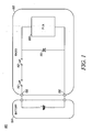
- FIG. 1 is a partial block diagram of a communication device 100 formed in accordance with an embodiment of the invention.
- Communication device 100 comprises a radio 102 and a battery 104 coupled to the radio via radio contacts 106 (Supply, GND).
- the radio 102 includes transceiver and controller circuitry, but for the purposes of this application only transmit power amplifier 108 is shown.
- Transmit power amplifier 108 utilizes a capacitor 110 across the supply and GND lines to smooth out peak currents associated with the power amplifier and/or other circuits within the radio.
- a plurality of switches 112 are coupled to at least one of the radio contacts 106 such that the switches are opened in response to the battery 104 being removed from the radio 102.
- switches 112 When opened, switches 112 provide isolation between the radio capacitor 110 and the radio contacts 106.
- the plurality of switches are cam operated mechanical switches which open when the battery is removed and close when the battery is attached.
- the impedance of the switches is not significant. While the plurality of switches 112 is shown as two switches for redundancy purposes, one switch may be used or more than two switches may also be used depending on the application.
- FIG. 2 shows a block diagram of a communication device 200 in accordance with another embodiment of the invention.
- communication device 200 comprises a radio 202 and a battery 204 coupled to the radio via radio contacts 206.
- the radio 202 includes known transceiver and controller circuitry, but for the purposes of this application only transmit power amplifier is shown.
- Transmit power amplifier 208 utilizes a capacitor 210 across the supply lines to smooth out peak currents associated with the power amplifier and/or other circuits.
- a plurality of switches 212 are coupled to at least one of the radio contacts 206 such that at least one switch is used to dissipate energy from the radio capacitor 210 through at least one discharge resistor 214.
- switches 212 When switches 212 are closed, discharge resistors 214 become parallel coupled to provide a discharge path between supply and GND.
- the plurality of switches 212 comprise parallel coupled cam operated mechanical switches that close when the battery is removed to dissipate energy from the capacitor 210 through the plurality of discharge resistors 214.
- FIG. 3 shows a block diagram of a communication device 300 in accordance with another embodiment of the invention.
- communication device 300 comprises a radio 302 and a battery 304 coupled to the radio via radio contacts 306.
- the radio 302 includes known transceiver and controller circuitry, but for the purposes of this application only transmit power amplifier 308 is shown.
- a plurality of parallel coupled capacitors 310 each capacitor having a series coupled diode, are coupled across the supply and GND lines.
- the use of the diodes 316 provides for isolation of circuitry of dissimilar voltages.
- Discharge resistor 314 provides a discharge path between supply and GND when the series coupled switches 312 are closed.
- the plurality of switches 312 comprise series coupled cam operated mechanical switches which close in response to the battery 304 being removed from the radio 302 to dissipate energy from the plurality of capacitors 310 through discharge resistor 314. While shown with two switches 312 for redundancy, one switch could also be used or more than two switches coupled be used depending on the application.
- FIG. 4 shows a block diagram of a communication device 400 in accordance with another embodiment of the invention.
- communication device 400 comprises a radio 402 and a battery 404 coupled to the radio via radio contacts 406.
- the radio 402 includes known transceiver and controller circuitry, but for the purposes of this application only transmit power amplifier 408 is shown.
- at least one capacitor 410 is coupled across the PA supply lines.
- This embodiment further includes first and second sensing circuits 430, 440 respectively, inrush current limiting circuit 450, and first and second switching circuits 460, 470 respectively.
- the first sensing circuit 430 is coupled to the radio contacts 406 and to the second sensing circuit 440.
- the second sensing circuit 440 is coupled to the first and second switching circuits 460, 470.
- the first sensing circuit 430 may be formed of a diode, voltage divider and capacitor (or similar configuration) to provide a predetermined time constant for the voltage going into the second sensing circuit 470.
- the differential voltage resulting from the voltage across storage capacitor 431 and the voltage at the voltage divider 441 causes the output of the comparator 442 to change output state.
- the residual voltage stored in capacitor 410 and the time constant of sense circuit 430 keeps the comparator 442 in this state until the voltage in capacitor 410 is dissipated.
- the second sensing circuit 440 includes a comparator 442 with resistor and capacitor biasing circuitry to set a predetermined comparator threshold and an inverter 444.
- the output of the comparator 442 controls first switching circuit switches 422.
- the output of the inverter 444 controls second switching circuit switches 412.
- the first and second switching circuit switches 412 and 422 comprise a plurality of electrical switches, such as transistor switches, which close and open in response to the sensing circuitry 430, 440 detecting removal of the battery from the radio and attachment of the battery to the radio.
- the first switching circuit 460 opens switches 422 to remove access to the stored energy of capacitor 410 from the contacts 406. Also upon removal of the battery, the second switching circuit 470 closes switches 412 to dissipate the stored energy from capacitor 410 through resistors 414.
- the embodiment of FIG. 4 provides the additional advantage of current limiting the inrush of current during attachment of the battery to the radio through inrush current limiting resistors 424 while the switches are open.
- the first switching circuit switches 422 Prior to attachment of the battery 404 to the radio 402, the first switching circuit switches 422 are open and the second switching circuit switches 412 are also open.
- the time constant associated with the first sensing circuit 430 maintains the output of the comparator 442 to hold the first switching circuit switches 422 open allowing current to flow from the battery 404 through resistors 424 to the PA 408.
- the inrush current limiting resistors 424 are selected to be large enough so that the current remains low enough to prevent sparking during this initial attachment phase.
- the first switching circuit switches 422 close and the inrush current limiting resistors 424 are bypassed.
- the second switching circuit switches remain open and full power is supplied to the PA 408.
- the time constant associated with the first sensing circuit 430 and the comparator threshold of the second sensing circuit 440 causes the first switching circuit switches 422 to open thereby isolating capacitor 410 from radio contacts 406.
- the inrush current limiting resistors 424 are of no significance in this condition.
- the output of inverter 444 closes the second switching circuit switches 412 thereby discharging the stored charge from capacitor 410 through resistors 414.
- the residual voltage stored in capacitor 410 and the time constant of sense circuit 430 keeps the comparator 442 in this state until the voltage in capacitor 410 is dissipated.
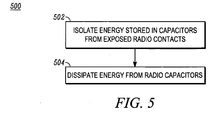
- FIG. 5 provides a flowchart summarizing the embodiments to prevent sparking as a battery is removed from a radio.
- Method 500 includes performing at least one of isolating energy stored in radio capacitors from exposed radio contacts 502 and/or dissipating energy from the radio capacitors 504. By switching a plurality of switches within the radio, and or using switcheably coupled resistors, intrinsically safe battery removal and attachment can be achieved in which sparking at the radio contacts is prevented - even if an inadvertent short occurs across the contacts 406.
- an intrinsically safe communication device in which sparking is prevented at the radio contacts during attachment and removal of the battery from the radio.
- the manner in which intrinsic safety is achieved also limits inrush current during attachment of the battery.
- the intrinsic safety approach provided by the various embodiments requires no change to the battery and eliminates the need for series diodes in the radio and further avoids the use of complex circuitry.
- Past approaches to intrinsic safety have utilized diodes in the radio to discharge the radio current, causing significant battery energy loss.
- the use of diodes in the radio may impose a voltage drop between 0.3 Volts and 0.6 Volts per diode.
- Past intrinsically safe applications have typically used two diodes in series. The voltage drop associated with two series diodes significantly decreases the effective capacity and available power of the battery, particularly in single-cell applications where the battery voltage is only 3-4 Volts accounting for as much as a 40% loss in battery power.
- the power dissipated in the diodes also adds heat to the radio.
- the intrinsic safety approach provided by the various embodiments requires no series diodes.
- a communication device having the intrinsic safety embodiments is prevented from sparking even if a possible short circuit discharge condition on the exposed radio contacts occurs.
- relational terms such as first and second, top and bottom, and the like may be used solely to distinguish one entity or action from another entity or action without necessarily requiring or implying any actual such relationship or order between such entities or actions.
- the terms “comprises,” “comprising,” “has”, “having,” “includes”, “including,” “contains”, “containing” or any other variation thereof, are intended to cover a non-exclusive inclusion, such that a process, method, article, or apparatus that comprises, has, includes, contains a list of elements does not include only those elements but may include other elements not expressly listed or inherent to such process, method, article, or apparatus.
- processors such as microprocessors, digital signal processors, customized processors and field programmable gate arrays (FPGAs) and unique stored program instructions (including both software and firmware) that control the one or more processors to implement, in conjunction with certain non-processor circuits, some, most, or all of the functions of the method and/or apparatus described herein.
- processors or “processing devices”
- FPGAs field programmable gate arrays
- unique stored program instructions including both software and firmware
Landscapes
- Engineering & Computer Science (AREA)
- Computer Networks & Wireless Communication (AREA)
- Signal Processing (AREA)
- Emergency Protection Circuit Devices (AREA)
- Charge And Discharge Circuits For Batteries Or The Like (AREA)
Claims (15)
- Kommunikationsvorrichtung (100), die umfasst:ein Funkgerät (102), das über einen Funkkondensator (110) und Funkkontakte (106) verfügt;eine Batterie (104), die über die Funkkontakte an das Funkgerät gekoppelt ist; unddass das Funkgerät (102) mindestens einen Schalter (112) umfasst, der an mindestens einen der Funkkontakte gekoppelt ist, wobei der mindestens eine Schalter (112) in Reaktion darauf aktiviert wird, dass die Batterie (104) von dem Funkgerät entfernt wird, wobei der mindestens eine Schalter eine Isolation des Funkkondensators (110) von den Funkkontakten (106) und/oder einen Energieverlust durch den Funkkondensator steuert.
- Kommunikationsvorrichtung (100) gemäß Anspruch 1, wobei der Funkkondensator (110) Spitzenströme an einen Senderleistungsverstärker (108) des Funkgerätes glättet.
- Kommunikationsvorrichtung (100) gemäß Anspruch 1 oder Anspruch 2, wobei der mindestens eine Schalter (112) öffnet, um den Funkkondensator (110) von den Funkkontakten (106) zu isolieren.
- Kommunikationsvorrichtung (200) gemäß Anspruch 1, wobei der mindestens eine Schalter (212) schließt, um Energie von dem Funkkondensator durch einen Entladungswiderstand (214) abzubauen.
- Kommunikationsvorrichtung (300) gemäß Anspruch 1, wobei das Funkgerät eine Mehrzahl von parallel geschalteten Kondensatoren (310) umfasst, von denen jeder über eine in Reihe geschaltete Diode (316) verfügt, wobei der mindestens eine Schalter eine Mehrzahl von in Reihe geschalteten Schaltern (312) umfasst, die schließen, um Energie von der Mehrzahl von parallel geschalteten Kondensatoren abzubauen.
- Kommunikationsvorrichtung (400) gemäß Anspruch 1, wobei das Funkgerät weiterhin umfasst:einen ersten Messkreis (430), der an die Funkkontakte gekoppelt ist;einen zweiten Messkreis (440), der an den ersten Messkreis gekoppelt ist;einen ersten Schaltkreis (460), der über erste Schaltkreisschalter (422) verfügt, um einen Zugriff auf die gespeicherte Energie des Funkkondensators von den Funkkontakten zu entfernen; undeinen zweiten Schaltkreis (470), der über zweite Schaltkreisschalter (412) verfügt,um die gespeicherte Energie des Funkkondensators abzubauen.
- Kommunikationsvorrichtung (400) gemäß Anspruch 6, wobei der erste Messkreis (430) über eine vorbestimmte Zeitkonstante verfügt und der zweite Messkreis (440) einen Komparator (422) mit einem vorbestimmten Komparatorschwellenwert und einen Inverter (444) umfasst.
- Kommunikationsvorrichtung (400) gemäß Anspruch 7, wobei die ersten Schaltkreisschalter (422) und die zweiten Schaltkreisschalter (412) vor einer Befestigung des Funkgerätes (402) an die Batterie (404) offen sind.
- Kommunikationsvorrichtung (400) gemäß Anspruch 8, wobei, nach einer Befestigung der Batterie (404) an das Funkgerät (402), die vorbestimmte Zeitkonstante des ersten Messkreises (430) die ersten Schaltkreisschalter (422) offen hält, bis der vorbestimmte Komparatorschwellenwert in dem zweiten Messkreis (440) erreicht ist, und die ersten Schaltkreisschalter (422) in Reaktion darauf, dass der vorbestimmte Komparatorschwellenwert erreicht wird, geschlossen werden.
- Kommunikationsvorrichtung (400) gemäß Anspruch 8 oder Anspruch 9, wobei, nach einem Entfernen der Batterie von dem Funkgerät, die vorbestimmte Zeitkonstante des ersten Messkreises (430) und der vorbestimmte Komparatorschwellenwert des zweiten Messkreises (440) die ersten Schaltkreisschalter (422) öffnen und die zweiten Schaltkreisschalter (412) schließen, wodurch Energie aus dem Funkkondensator entladen wird.
- Kommunikationsvorrichtung (400) gemäß einem der Ansprüche 6 - 10, die weiterhin einen Einschaltstrom begrenzende Widerstände (424) umfasst, die einen Funkstrom begrenzen, wenn die ersten Schaltkreisschalter (422) während der vorbestimmten Zeitkonstante, die nach einer Befestigung der Batterie an das Funkgerät mit dem ersten Messkreis (430) verknüpft ist, offen sind.
- Verfahren zur eigensicheren Batteriebefestigung und -entfernung von einem Funkgerät, das umfasst:Schalten einer Mehrzahl von Schaltern in dem Funkgerät, wenn die Batterie von dem Funkgerät entfernt wird, um ein Isolieren von Energie (502), die in Funkkondensatoren gespeichert ist, von freigelegten Funkkontakten und ein Abbauen von Energie (504) in den Funkkondensatoren durchzuführen.
- Verfahren gemäß Anspruch 12, wobei der Schritt eines Schaltens ohne eine Verwendung von in Reihe geschalteten Dioden bei den Funkkontakten durchgeführt wird.
- Verfahren gemäß Anspruch 13, wobei der Schritt eines Isolierens umfasst:Öffnen der Mehrzahl von Schaltern, um die Funkkondensatoren zu isolieren, bevor die Funkkontakte freigelegt werden.
- Verfahren gemäß Anspruch 13, wobei der Schritt eines Isolierens umfasst:Schließen der Mehrzahl von Schaltern, um Energie aus den Funkkondensatoren durch mindestens einen Entladungswiderstand zu entladen.
Applications Claiming Priority (2)
| Application Number | Priority Date | Filing Date | Title |
|---|---|---|---|
| US12/488,926 US8805455B2 (en) | 2009-06-22 | 2009-06-22 | Method and apparatus for intrinsically safe operation of a communication device |
| PCT/US2010/036270 WO2010151393A1 (en) | 2009-06-22 | 2010-05-27 | Method and apparatus for intrinsically safe operation of a communication device |
Publications (2)
| Publication Number | Publication Date |
|---|---|
| EP2446515A1 EP2446515A1 (de) | 2012-05-02 |
| EP2446515B1 true EP2446515B1 (de) | 2014-08-06 |
Family
ID=42554303
Family Applications (1)
| Application Number | Title | Priority Date | Filing Date |
|---|---|---|---|
| EP10730888.4A Active EP2446515B1 (de) | 2009-06-22 | 2010-05-27 | Verfahren und gerät zum eigensicheren betreiben einer kommunikationseinrichtung |
Country Status (4)
| Country | Link |
|---|---|
| US (1) | US8805455B2 (de) |
| EP (1) | EP2446515B1 (de) |
| CN (1) | CN102460884B (de) |
| WO (1) | WO2010151393A1 (de) |
Families Citing this family (7)
| Publication number | Priority date | Publication date | Assignee | Title |
|---|---|---|---|---|
| CN103311977A (zh) * | 2012-03-16 | 2013-09-18 | 鸿富锦精密工业(深圳)有限公司 | 便携式电子设备供电维持电路和方法 |
| KR102058523B1 (ko) * | 2013-10-10 | 2020-01-22 | 인텔 코포레이션 | 소형 폼팩터 디바이스에서의 구조적 강도 증가, 사이즈 감소, 안전성 개선, 열성능 향상 및 충전 가속화를 위한 재료의 사용 |
| JP6466133B2 (ja) * | 2014-10-22 | 2019-02-06 | 三菱重工サーマルシステムズ株式会社 | 電気回路、電動圧縮機および電気回路の制御方法 |
| CN105633938B (zh) * | 2016-03-09 | 2018-09-11 | 广东欧珀移动通信有限公司 | 电池输入系统及终端设备 |
| DE102018125272A1 (de) * | 2018-10-12 | 2020-04-16 | Valeo Siemens Eautomotive Germany Gmbh | Vorrichtung und Verfahren zum Entladen eines Zwischenkreiskondensators, Stromrichter und Fahrzeug |
| US10879519B2 (en) | 2018-12-17 | 2020-12-29 | Bayco Products, Inc. | Spark protection apparatus for intrinsically safe, battery-operated devices |
| US10601981B1 (en) | 2018-12-20 | 2020-03-24 | Motorola Solutions, Inc. | Apparatus and method for intrinsically safe operation of a portable communication device |
Family Cites Families (25)
| Publication number | Priority date | Publication date | Assignee | Title |
|---|---|---|---|---|
| US4638396A (en) | 1984-12-31 | 1987-01-20 | Motorola, Inc. | Intrinsically safe battery circuit |
| US4992340A (en) | 1989-04-20 | 1991-02-12 | Motorola, Inc. | Intrinsic safe battery having self test capability |
| DE3934577A1 (de) | 1989-10-17 | 1991-04-18 | Philips Patentverwaltung | Stromversorgungseinrichtung mit einschaltstrombegrenzungsschaltung |
| US5218284A (en) | 1990-12-31 | 1993-06-08 | Motorola, Inc. | Integral battery charging and supply regulation circuit |
| US5206538A (en) * | 1991-04-03 | 1993-04-27 | At&T Bell Laboratories | Automatic system battery reconnect circuit responsive to insertion of new battery replacement |
| US5335133A (en) | 1991-11-29 | 1994-08-02 | Motorola, Inc. | Dual output battery with fault detect |
| JPH0638280A (ja) | 1992-07-21 | 1994-02-10 | Fujitsu General Ltd | リモコン送信機 |
| US5587250A (en) * | 1995-09-27 | 1996-12-24 | Motorola, Inc. | Hybrid energy storage system |
| US6087812A (en) * | 1997-06-13 | 2000-07-11 | Motorola, Inc. | Independent dual-switch system for extending battery life under transient loads |
| GB9716142D0 (en) | 1997-08-01 | 1997-10-08 | Philips Electronics Nv | Extending battery life in electronic apparatus |
| US6789205B1 (en) | 2000-05-19 | 2004-09-07 | Motorola, Inc. | System for determining intrinsic safety status of the combination of a communication device and a battery |
| GB0016524D0 (en) | 2000-07-06 | 2000-08-23 | Mtl Instr Group The Plc | Protection of incendive circuits |
| GB2384354A (en) * | 2002-01-18 | 2003-07-23 | Yeoman Group Plc | Navigation System |
| US6859020B2 (en) * | 2002-10-15 | 2005-02-22 | Texas Instruments Incorporated | Low power mode detection circuit for a DC/DC converter |
| KR100498047B1 (ko) * | 2003-03-05 | 2005-07-01 | 삼성전자주식회사 | 과전류 차단 기능을 갖는 모바일 디바이스 |
| US7607571B2 (en) * | 2003-05-30 | 2009-10-27 | Intellidot Corporation | Medical work flow system |
| US7130665B2 (en) | 2003-08-26 | 2006-10-31 | Motorola, Inc. | Method and apparatus to ensure intrinsically safe operation of a communication device |
| US6902412B2 (en) | 2003-08-26 | 2005-06-07 | Motorola, Inc. | Apparatus for intrinsically safe power interface |
| DE102005002490A1 (de) | 2005-01-19 | 2006-07-27 | Hella Kgaa Hueck & Co. | Vorrichtung und Verfahren zum Schließen und Öffnen eines Kraftfahrzeugbordnetzes |
| US7323828B2 (en) * | 2005-04-25 | 2008-01-29 | Catalyst Semiconductor, Inc. | LED current bias control using a step down regulator |
| US7573156B2 (en) * | 2005-12-22 | 2009-08-11 | American Power Conversion Corporation | Apparatus for and method of connecting a power source to a device |
| US20080100976A1 (en) | 2006-07-25 | 2008-05-01 | Kh Controls, Inc. | Limiting energy in wiring faults combined upstream and downstream protection |
| DE102006046288B3 (de) * | 2006-09-29 | 2007-11-29 | Siemens Ag | Verstärkereinrichtung mit einstellbarer Versorgungsspannung |
| US7408755B1 (en) * | 2007-06-12 | 2008-08-05 | Honeywell International Inc. | Advanced inrush/transient current limit and overload/short circuit protection method and apparatus for DC voltage power supply |
| US7945295B2 (en) | 2007-12-03 | 2011-05-17 | Motorola Solutions, Inc. | Portable radio and battery pack configuration |
-
2009
- 2009-06-22 US US12/488,926 patent/US8805455B2/en active Active
-
2010
- 2010-05-27 EP EP10730888.4A patent/EP2446515B1/de active Active
- 2010-05-27 WO PCT/US2010/036270 patent/WO2010151393A1/en not_active Ceased
- 2010-05-27 CN CN201080027709.0A patent/CN102460884B/zh active Active
Also Published As
| Publication number | Publication date |
|---|---|
| US20100323766A1 (en) | 2010-12-23 |
| EP2446515A1 (de) | 2012-05-02 |
| CN102460884B (zh) | 2015-01-07 |
| US8805455B2 (en) | 2014-08-12 |
| WO2010151393A1 (en) | 2010-12-29 |
| CN102460884A (zh) | 2012-05-16 |
Similar Documents
| Publication | Publication Date | Title |
|---|---|---|
| US8805455B2 (en) | Method and apparatus for intrinsically safe operation of a communication device | |
| EP2363936B1 (de) | Vorrichtung zum Schutz gegen umgekehrten Anschluss und Notstromversorgung damit | |
| CN105305565B (zh) | 一种充电保护及识别电路及待充电设备 | |
| US20020097543A1 (en) | Charge/discharge protection circuit for a rechargeable battery | |
| KR102005703B1 (ko) | 배터리 보호 ic 및 배터리 장치 | |
| US20200381929A1 (en) | Battery protective circuit and battery pack comprising same | |
| WO2019017263A1 (ja) | 電池の保護回路とこの保護回路を備える電源装置 | |
| US7235950B2 (en) | Protection circuit limiting current applied to peripheral devices | |
| US20180152785A1 (en) | Audio power circuit and method | |
| EP4258511B1 (de) | Überentladungsschutzschaltung, batterieschutzplatte und elektronische vorrichtung | |
| US20130235500A1 (en) | Protection circuit for lithium-ion battery | |
| US10103556B2 (en) | Load side method of blocking charger voltage from a battery load | |
| US20110012564A1 (en) | Dc power tool with a safety detection device | |
| US20120187911A1 (en) | Output circuit, temperature switch ic, and battery pack | |
| US20140095916A1 (en) | Power supply circuit for pci-e and motherboard having same | |
| US20210265846A1 (en) | Battery protection circuit with active protection bypass | |
| US20140167702A1 (en) | Charging and discharging control circuit and battery device | |
| US6556401B1 (en) | Circuit arrangement for overload protection | |
| JP4718384B2 (ja) | 保護装置 | |
| CN101728841B (zh) | 电池盒 | |
| KR19990083573A (ko) | 지연회로 | |
| CN108574272A (zh) | 一种应用于无线供电系统的保护电路及无线供电系统 | |
| US11502520B2 (en) | Battery protection circuit with isolation device failure detection | |
| JP7192877B2 (ja) | 電気機器システム | |
| WO2015019627A1 (ja) | 過電流保護装置 |
Legal Events
| Date | Code | Title | Description |
|---|---|---|---|
| PUAI | Public reference made under article 153(3) epc to a published international application that has entered the european phase |
Free format text: ORIGINAL CODE: 0009012 |
|
| 17P | Request for examination filed |
Effective date: 20120123 |
|
| AK | Designated contracting states |
Kind code of ref document: A1 Designated state(s): AL AT BE BG CH CY CZ DE DK EE ES FI FR GB GR HR HU IE IS IT LI LT LU LV MC MK MT NL NO PL PT RO SE SI SK SM TR |
|
| DAX | Request for extension of the european patent (deleted) | ||
| GRAP | Despatch of communication of intention to grant a patent |
Free format text: ORIGINAL CODE: EPIDOSNIGR1 |
|
| INTG | Intention to grant announced |
Effective date: 20140311 |
|
| GRAS | Grant fee paid |
Free format text: ORIGINAL CODE: EPIDOSNIGR3 |
|
| GRAA | (expected) grant |
Free format text: ORIGINAL CODE: 0009210 |
|
| AK | Designated contracting states |
Kind code of ref document: B1 Designated state(s): AL AT BE BG CH CY CZ DE DK EE ES FI FR GB GR HR HU IE IS IT LI LT LU LV MC MK MT NL NO PL PT RO SE SI SK SM TR |
|
| REG | Reference to a national code |
Ref country code: GB Ref legal event code: FG4D |
|
| REG | Reference to a national code |
Ref country code: AT Ref legal event code: REF Ref document number: 681417 Country of ref document: AT Kind code of ref document: T Effective date: 20140815 Ref country code: CH Ref legal event code: EP |
|
| REG | Reference to a national code |
Ref country code: IE Ref legal event code: FG4D |
|
| REG | Reference to a national code |
Ref country code: DE Ref legal event code: R096 Ref document number: 602010018046 Country of ref document: DE Effective date: 20140918 |
|
| REG | Reference to a national code |
Ref country code: AT Ref legal event code: MK05 Ref document number: 681417 Country of ref document: AT Kind code of ref document: T Effective date: 20140806 |
|
| REG | Reference to a national code |
Ref country code: NL Ref legal event code: VDEP Effective date: 20140806 |
|
| REG | Reference to a national code |
Ref country code: LT Ref legal event code: MG4D |
|
| PG25 | Lapsed in a contracting state [announced via postgrant information from national office to epo] |
Ref country code: GR Free format text: LAPSE BECAUSE OF FAILURE TO SUBMIT A TRANSLATION OF THE DESCRIPTION OR TO PAY THE FEE WITHIN THE PRESCRIBED TIME-LIMIT Effective date: 20141107 Ref country code: PT Free format text: LAPSE BECAUSE OF FAILURE TO SUBMIT A TRANSLATION OF THE DESCRIPTION OR TO PAY THE FEE WITHIN THE PRESCRIBED TIME-LIMIT Effective date: 20141209 Ref country code: SE Free format text: LAPSE BECAUSE OF FAILURE TO SUBMIT A TRANSLATION OF THE DESCRIPTION OR TO PAY THE FEE WITHIN THE PRESCRIBED TIME-LIMIT Effective date: 20140806 Ref country code: LT Free format text: LAPSE BECAUSE OF FAILURE TO SUBMIT A TRANSLATION OF THE DESCRIPTION OR TO PAY THE FEE WITHIN THE PRESCRIBED TIME-LIMIT Effective date: 20140806 Ref country code: NO Free format text: LAPSE BECAUSE OF FAILURE TO SUBMIT A TRANSLATION OF THE DESCRIPTION OR TO PAY THE FEE WITHIN THE PRESCRIBED TIME-LIMIT Effective date: 20141106 Ref country code: BG Free format text: LAPSE BECAUSE OF FAILURE TO SUBMIT A TRANSLATION OF THE DESCRIPTION OR TO PAY THE FEE WITHIN THE PRESCRIBED TIME-LIMIT Effective date: 20141106 Ref country code: FI Free format text: LAPSE BECAUSE OF FAILURE TO SUBMIT A TRANSLATION OF THE DESCRIPTION OR TO PAY THE FEE WITHIN THE PRESCRIBED TIME-LIMIT Effective date: 20140806 Ref country code: ES Free format text: LAPSE BECAUSE OF FAILURE TO SUBMIT A TRANSLATION OF THE DESCRIPTION OR TO PAY THE FEE WITHIN THE PRESCRIBED TIME-LIMIT Effective date: 20140806 |
|
| PG25 | Lapsed in a contracting state [announced via postgrant information from national office to epo] |
Ref country code: CY Free format text: LAPSE BECAUSE OF FAILURE TO SUBMIT A TRANSLATION OF THE DESCRIPTION OR TO PAY THE FEE WITHIN THE PRESCRIBED TIME-LIMIT Effective date: 20140806 Ref country code: PL Free format text: LAPSE BECAUSE OF FAILURE TO SUBMIT A TRANSLATION OF THE DESCRIPTION OR TO PAY THE FEE WITHIN THE PRESCRIBED TIME-LIMIT Effective date: 20140806 Ref country code: AT Free format text: LAPSE BECAUSE OF FAILURE TO SUBMIT A TRANSLATION OF THE DESCRIPTION OR TO PAY THE FEE WITHIN THE PRESCRIBED TIME-LIMIT Effective date: 20140806 Ref country code: IS Free format text: LAPSE BECAUSE OF FAILURE TO SUBMIT A TRANSLATION OF THE DESCRIPTION OR TO PAY THE FEE WITHIN THE PRESCRIBED TIME-LIMIT Effective date: 20141206 Ref country code: NL Free format text: LAPSE BECAUSE OF FAILURE TO SUBMIT A TRANSLATION OF THE DESCRIPTION OR TO PAY THE FEE WITHIN THE PRESCRIBED TIME-LIMIT Effective date: 20140806 Ref country code: HR Free format text: LAPSE BECAUSE OF FAILURE TO SUBMIT A TRANSLATION OF THE DESCRIPTION OR TO PAY THE FEE WITHIN THE PRESCRIBED TIME-LIMIT Effective date: 20140806 Ref country code: LV Free format text: LAPSE BECAUSE OF FAILURE TO SUBMIT A TRANSLATION OF THE DESCRIPTION OR TO PAY THE FEE WITHIN THE PRESCRIBED TIME-LIMIT Effective date: 20140806 |
|
| PG25 | Lapsed in a contracting state [announced via postgrant information from national office to epo] |
Ref country code: RO Free format text: LAPSE BECAUSE OF FAILURE TO SUBMIT A TRANSLATION OF THE DESCRIPTION OR TO PAY THE FEE WITHIN THE PRESCRIBED TIME-LIMIT Effective date: 20140806 Ref country code: CZ Free format text: LAPSE BECAUSE OF FAILURE TO SUBMIT A TRANSLATION OF THE DESCRIPTION OR TO PAY THE FEE WITHIN THE PRESCRIBED TIME-LIMIT Effective date: 20140806 Ref country code: DK Free format text: LAPSE BECAUSE OF FAILURE TO SUBMIT A TRANSLATION OF THE DESCRIPTION OR TO PAY THE FEE WITHIN THE PRESCRIBED TIME-LIMIT Effective date: 20140806 Ref country code: EE Free format text: LAPSE BECAUSE OF FAILURE TO SUBMIT A TRANSLATION OF THE DESCRIPTION OR TO PAY THE FEE WITHIN THE PRESCRIBED TIME-LIMIT Effective date: 20140806 Ref country code: SK Free format text: LAPSE BECAUSE OF FAILURE TO SUBMIT A TRANSLATION OF THE DESCRIPTION OR TO PAY THE FEE WITHIN THE PRESCRIBED TIME-LIMIT Effective date: 20140806 Ref country code: IT Free format text: LAPSE BECAUSE OF FAILURE TO SUBMIT A TRANSLATION OF THE DESCRIPTION OR TO PAY THE FEE WITHIN THE PRESCRIBED TIME-LIMIT Effective date: 20140806 |
|
| REG | Reference to a national code |
Ref country code: DE Ref legal event code: R097 Ref document number: 602010018046 Country of ref document: DE |
|
| PLBE | No opposition filed within time limit |
Free format text: ORIGINAL CODE: 0009261 |
|
| STAA | Information on the status of an ep patent application or granted ep patent |
Free format text: STATUS: NO OPPOSITION FILED WITHIN TIME LIMIT |
|
| 26N | No opposition filed |
Effective date: 20150507 |
|
| PG25 | Lapsed in a contracting state [announced via postgrant information from national office to epo] |
Ref country code: SI Free format text: LAPSE BECAUSE OF FAILURE TO SUBMIT A TRANSLATION OF THE DESCRIPTION OR TO PAY THE FEE WITHIN THE PRESCRIBED TIME-LIMIT Effective date: 20140806 |
|
| REG | Reference to a national code |
Ref country code: CH Ref legal event code: PL |
|
| PG25 | Lapsed in a contracting state [announced via postgrant information from national office to epo] |
Ref country code: LU Free format text: LAPSE BECAUSE OF FAILURE TO SUBMIT A TRANSLATION OF THE DESCRIPTION OR TO PAY THE FEE WITHIN THE PRESCRIBED TIME-LIMIT Effective date: 20150527 Ref country code: MC Free format text: LAPSE BECAUSE OF FAILURE TO SUBMIT A TRANSLATION OF THE DESCRIPTION OR TO PAY THE FEE WITHIN THE PRESCRIBED TIME-LIMIT Effective date: 20140806 Ref country code: CH Free format text: LAPSE BECAUSE OF NON-PAYMENT OF DUE FEES Effective date: 20150531 Ref country code: LI Free format text: LAPSE BECAUSE OF NON-PAYMENT OF DUE FEES Effective date: 20150531 |
|
| REG | Reference to a national code |
Ref country code: IE Ref legal event code: MM4A |
|
| REG | Reference to a national code |
Ref country code: FR Ref legal event code: PLFP Year of fee payment: 7 |
|
| PG25 | Lapsed in a contracting state [announced via postgrant information from national office to epo] |
Ref country code: IE Free format text: LAPSE BECAUSE OF NON-PAYMENT OF DUE FEES Effective date: 20150527 |
|
| PG25 | Lapsed in a contracting state [announced via postgrant information from national office to epo] |
Ref country code: BE Free format text: LAPSE BECAUSE OF FAILURE TO SUBMIT A TRANSLATION OF THE DESCRIPTION OR TO PAY THE FEE WITHIN THE PRESCRIBED TIME-LIMIT Effective date: 20140806 |
|
| REG | Reference to a national code |
Ref country code: DE Ref legal event code: R082 Ref document number: 602010018046 Country of ref document: DE Representative=s name: SCHUMACHER & WILLSAU PATENTANWALTSGESELLSCHAFT, DE Ref country code: DE Ref legal event code: R081 Ref document number: 602010018046 Country of ref document: DE Owner name: MOTOROLA SOLUTIONS, INC., CHICAGO, US Free format text: FORMER OWNER: MOTOROLA SOLUTIONS, INC., SCHAUMBURG, ILL., US |
|
| PG25 | Lapsed in a contracting state [announced via postgrant information from national office to epo] |
Ref country code: MT Free format text: LAPSE BECAUSE OF FAILURE TO SUBMIT A TRANSLATION OF THE DESCRIPTION OR TO PAY THE FEE WITHIN THE PRESCRIBED TIME-LIMIT Effective date: 20140806 |
|
| REG | Reference to a national code |
Ref country code: FR Ref legal event code: PLFP Year of fee payment: 8 |
|
| PG25 | Lapsed in a contracting state [announced via postgrant information from national office to epo] |
Ref country code: SM Free format text: LAPSE BECAUSE OF FAILURE TO SUBMIT A TRANSLATION OF THE DESCRIPTION OR TO PAY THE FEE WITHIN THE PRESCRIBED TIME-LIMIT Effective date: 20140806 Ref country code: HU Free format text: LAPSE BECAUSE OF FAILURE TO SUBMIT A TRANSLATION OF THE DESCRIPTION OR TO PAY THE FEE WITHIN THE PRESCRIBED TIME-LIMIT; INVALID AB INITIO Effective date: 20100527 |
|
| PG25 | Lapsed in a contracting state [announced via postgrant information from national office to epo] |
Ref country code: TR Free format text: LAPSE BECAUSE OF FAILURE TO SUBMIT A TRANSLATION OF THE DESCRIPTION OR TO PAY THE FEE WITHIN THE PRESCRIBED TIME-LIMIT Effective date: 20140806 |
|
| REG | Reference to a national code |
Ref country code: FR Ref legal event code: CA Effective date: 20180105 |
|
| REG | Reference to a national code |
Ref country code: FR Ref legal event code: PLFP Year of fee payment: 9 |
|
| PG25 | Lapsed in a contracting state [announced via postgrant information from national office to epo] |
Ref country code: MK Free format text: LAPSE BECAUSE OF FAILURE TO SUBMIT A TRANSLATION OF THE DESCRIPTION OR TO PAY THE FEE WITHIN THE PRESCRIBED TIME-LIMIT Effective date: 20140806 |
|
| PG25 | Lapsed in a contracting state [announced via postgrant information from national office to epo] |
Ref country code: AL Free format text: LAPSE BECAUSE OF FAILURE TO SUBMIT A TRANSLATION OF THE DESCRIPTION OR TO PAY THE FEE WITHIN THE PRESCRIBED TIME-LIMIT Effective date: 20140806 |
|
| P01 | Opt-out of the competence of the unified patent court (upc) registered |
Effective date: 20230523 |
|
| PGFP | Annual fee paid to national office [announced via postgrant information from national office to epo] |
Ref country code: DE Payment date: 20250423 Year of fee payment: 16 |
|
| PGFP | Annual fee paid to national office [announced via postgrant information from national office to epo] |
Ref country code: GB Payment date: 20250423 Year of fee payment: 16 |
|
| PGFP | Annual fee paid to national office [announced via postgrant information from national office to epo] |
Ref country code: FR Payment date: 20250423 Year of fee payment: 16 |
|
| REG | Reference to a national code |
Ref country code: DE Ref legal event code: R082 Ref document number: 602010018046 Country of ref document: DE Representative=s name: PUSCHMANN BORCHERT KAISER KLETTNER PATENTANWAE, DE Ref country code: DE Ref legal event code: R082 Ref document number: 602010018046 Country of ref document: DE Representative=s name: PATCARE PATENTANWAELTE PARTNERSCHAFT MBB, DE |