EP2446089B1 - Vorrichtung und verfahren zur bodenverbesserung - Google Patents
Vorrichtung und verfahren zur bodenverbesserung Download PDFInfo
- Publication number
- EP2446089B1 EP2446089B1 EP10797500.5A EP10797500A EP2446089B1 EP 2446089 B1 EP2446089 B1 EP 2446089B1 EP 10797500 A EP10797500 A EP 10797500A EP 2446089 B1 EP2446089 B1 EP 2446089B1
- Authority
- EP
- European Patent Office
- Prior art keywords
- tines
- top plate
- feet
- ground
- tsf
- Prior art date
- Legal status (The legal status is an assumption and is not a legal conclusion. Google has not performed a legal analysis and makes no representation as to the accuracy of the status listed.)
- Active
Links
Images


Classifications
-
- E—FIXED CONSTRUCTIONS
- E02—HYDRAULIC ENGINEERING; FOUNDATIONS; SOIL SHIFTING
- E02D—FOUNDATIONS; EXCAVATIONS; EMBANKMENTS; UNDERGROUND OR UNDERWATER STRUCTURES
- E02D3/00—Improving or preserving soil or rock, e.g. preserving permafrost soil
- E02D3/02—Improving by compacting
- E02D3/046—Improving by compacting by tamping or vibrating, e.g. with auxiliary watering of the soil
- E02D3/054—Improving by compacting by tamping or vibrating, e.g. with auxiliary watering of the soil involving penetration of the soil, e.g. vibroflotation
-
- E—FIXED CONSTRUCTIONS
- E02—HYDRAULIC ENGINEERING; FOUNDATIONS; SOIL SHIFTING
- E02D—FOUNDATIONS; EXCAVATIONS; EMBANKMENTS; UNDERGROUND OR UNDERWATER STRUCTURES
- E02D3/00—Improving or preserving soil or rock, e.g. preserving permafrost soil
- E02D3/02—Improving by compacting
- E02D3/046—Improving by compacting by tamping or vibrating, e.g. with auxiliary watering of the soil
-
- E—FIXED CONSTRUCTIONS
- E02—HYDRAULIC ENGINEERING; FOUNDATIONS; SOIL SHIFTING
- E02D—FOUNDATIONS; EXCAVATIONS; EMBANKMENTS; UNDERGROUND OR UNDERWATER STRUCTURES
- E02D3/00—Improving or preserving soil or rock, e.g. preserving permafrost soil
- E02D3/12—Consolidating by placing solidifying or pore-filling substances in the soil
- E02D3/123—Consolidating by placing solidifying or pore-filling substances in the soil and compacting the soil
Definitions
- the present invention is related to an apparatus and method for improving the strength and stiffness of soil by treating the soil with a displacement device having a plurality of tines, and optionally subsequently filling voids made by the device with flowable media such as, for example, sand, gravel, recycled materials, waste materials, tire chips, grout, or concrete.
- flowable media such as, for example, sand, gravel, recycled materials, waste materials, tire chips, grout, or concrete.
- Deep foundations Heavy or settlement-sensitive facilities that are located in areas containing soft, loose, or weak soils are often supported on deep foundations.
- Such deep foundations are typically made from driven pilings or concrete piers installed after drilling.
- the deep foundations are designed to transfer structural loads through the soft soils to more competent soil strata. Deep foundations are often relatively expensive when compared to other construction methods.
- Another way to support such structures is to excavate out the soft, loose, or weak soils and then fill the excavation with more competent material.
- the entire area under the building foundation is normally excavated and replaced to the depth of the soft, loose, or weak soil.
- This method is advantageous because it is performed with conventional earthwork methods, but has the disadvantages of being costly when performed in urban areas and may require that costly dewatering or shoring be performed to stabilize the excavation.
- Yet another way to support such structures is to treat the soil with "deep dynamic compaction" consisting of dropping a heavy weight on the ground surface.
- the weight is dropped from a sufficient height to cause a large compression wave to develop in the soil.
- the compression wave compacts the soil, provided the soil is of a sufficient gradation to be treatable.
- a variety of weight shapes are available to achieve compaction by this method, such as those described in U.S. Patent No. 6,505,998 .
- deep dynamic compaction may be economical for certain sites, it has the disadvantage that it induces large waves as a result of the weight hitting the ground. These waves may be damaging to structures.
- the technique is deficient because it is only applicable to a small band of soil gradations (particle sizes) and is not suitable for materials with appreciable fine-sized particles. What is needed in the field is a system that can rapidly improve cohesionless, cohesive, and semi-cohesive soils without inducing damaging vibrations.
- ground reinforcement with aggregate columns has been used to support structures located in areas containing layers of soft soils.
- the columns are designed to reinforce and strengthen the soft layers and reduce settlements.
- Such piers are constructed using a variety of methods including drilling and tamping methods such as described in U.S. Patent Nos. 5,249,892 and 6,354,766 ("Short Aggregate Piers"), driven mandrel methods such as described in U.S. Patent No. 6,425,713 (“Lateral Displacement Pier”), and tamping head driven mandrel methods such as described in U.S. Patent No. 7,226,246 (“Impact ® " system).
- the "Short Aggregate Pier” technique referenced above such as described in U.S. Patent No. 5,249,892 , which includes drilling or excavating a cavity, is an effective foundation solution, especially when installed in cohesive soils where the sidewall stability of the hole is easily maintained.
- the Short Aggregate Pier method may, theoretically, also be applied to multiple holes at once.
- this technique has the disadvantages of requiring casing in granular soils with collapsing holes and of necessitating the filling of the holes prior to tamping.
- the system is limited to very shallow treatment depths such as those needed for improvement below pavements.
- Needed in the field is a system that overcomes these deficiencies by allowing soil improvement to a wide range of soil conditions without the necessity of filling the holes between tamping passes and of being able to treat to deeper depths required for the support of shallow spread footings.
- the "Lateral Displacement Pier” and “Impact ® " system methods were developed for aggregate column installations in granular soils where the sidewall stability of the cavity is not easily maintained.
- the Lateral Displacement Pier is built as described in U.S. Patent No. 6,425,713 by driving a pipe into the ground, drilling out the soil inside the pipe, filling the pipe with aggregate, and using the pipe to compact the aggregate "in thin lifts.” A beveled edge is typically used at the bottom of the pipe for compaction.
- the Impact ® system is an extension of the Lateral Displacement Pier. In this case, a smaller diameter (8 to 20 inches) (20.32 to 50.8cm) tamper head is driven into the ground as disclosed in U.S. Patent No. 7,226,246 .
- the tamper head is attached to a pipe, which is filled with crushed stone once the tamper head is driven to the design depth. The tamper head is then lifted, thereby allowing stone to remain in the cavity, and then the tamper head is driven back down in order to densify each lift of aggregate.
- An advantage of the Impact ® system, over the Lateral Displacement Pier, is the speed of construction.
- the "Rampact ® " system is yet another displacement method in which a single conical shaped mandrel is driven into the ground and then filled with crushed stone as described in U.S. Patent No. 7,326,004 .
- the mandrel is hollow and fitted with a sacrificial plate or a valve mechanism at the bottom. The mandrel is later lifted to allow the rock to flow out of the bottom of the mandrel. The mandrel is then redriven back down into the cavity to compact the stone.
- the pier is constructed incrementally upwards in thin lifts from the bottom.
- EP0672794 , GB2217427 , RU2116193C1 and FR2482155A1 disclose other densification devices.
- GB2217427 is the closest prior art in respect to the application and it refers to a method of compacting granular insulating material in the annular space between an inner shell and an outer wall of a storage tank utilises an apparatus comprising a carrier, means for moving the carrier around the space, and a plurality of elongated pokers supported by and depending from the carrier.
- the method comprises periodically lowering the carrier to immerse the pokers into the granular material and then raising the carrier to withdraw the pokers from the granular material and periodically moving the carrier to different positions with the pokers withdrawn from the granular material.
- a device for ground improvement comprises a top plate having a first surface configured for having a driving device attached thereto to provide impact thereon; a plurality of vertically extending tines attached to a second surface of the top plate opposite the first surface of the top plate, and horizontally spaced from each other at upper lateral edges thereof, for being driven into a ground surface; and the tines being shaped, spaced, and oriented relative to each other in a manner to achieve displacement of ground material downward and radially outward.
- the tines can be tapered to be narrower at an end away from the top plate than at the attachment to the second surface of the top plate.
- the tines can be tapered at an angle in the range of 0° to 5°, and more specifically, at an angle in the range of 0.5° to 2.5°.
- the tines can have a length in the range of 2-30 feet (0.6096-9.144 meters), can be circular in cross-section, or articulated in cross-section.
- the tines can be substantially flat at an end away from the top plate, substantially pointed at an end away from the top plate, or have a bulbous shape at an end away from the top plate.
- the tines can be made of ferrous material, steel, or composite materials.
- the tines can be hollow and have openings at the ends away from the top plate and respective valves at the openings for restricting entry of soil during advancement, and for allowing passage of flowable material outward during retraction.
- the hollow tines can also have openings at the ends away from the top plate, and respective sacrificial plates at the openings.
- the plurality of tines comprises five tines horizontally spaced from each other, with four perimeter tines spaced about the periphery of the top plate and surrounding a centrally located tine. The four perimeter tines can be oriented at 45° about their vertical axis relative to the centrally located tine. In another exemplary embodiment, the plurality of tines comprises eleven tines horizontally spaced from each other, with eight perimeter tines spaced about the periphery of the top plate and surrounding three centrally located tines. The eight perimeter tines can be oriented at 45° about their vertical axis relative to the centrally located tines.
- a method for ground improvement comprises providing a device for ground improvement comprised of a top plate having a first surface configured for having a driving device attached thereto to provide impact thereon, and a plurality of vertically extending tines attached to a second surface of the top plate opposite the first surface of the top plate, and horizontally spaced from each other at upper lateral edges thereof, for being driven into a ground surface, and the tines being shaped, spaced, and oriented relative to each other in a manner to achieve displacement of ground material downward and radially outward; advancing the device tines into the ground surface; retracting the tines from the ground surface; repeating the advancing and retracting until a desired ground condition is achieved.
- the advancing of the tines creates cavities at the location the tines are advanced, and the method further comprises adding backfill into the cavities and advancing and retracting the device repeatedly after the backfill has been added.
- the tines can be hollow and each have an opening at an end away from the surface plate, such that backfill can be added through the tines and out the opening of each tine upon retraction thereof.
- the tines can have respective valves at the open ends, and the method comprises keeping the valves closed upon advancement of the device and opening the valves upon retraction, and adding the backfill through the tines.
- the tines can also have respective sacrificial plates at the open ends, and the method comprises securing the sacrificial plates to the tines upon advancement of the device and allowing the sacrificial plates to separate from the tines upon retraction, and adding the backfill through the tines.
- the backfill can be one of or a combination of crushed stone, sand, aggregate, gravel, grout, concrete, lime, fly ash, waste materials, tire chips, recycled materials, and other flowable substances.
- the level of ground improvement achieved can be measured through a monitoring of downward pressure during penetration for a determination of degree of densification.
- the invention includes an apparatus and method for improving the strength and stiffness of in-situ subsurface materials, e.g., soil in a grounded surface, prior to loading by buildings, slabs, walls, tanks, transportation structures, industrial works, and other structures.
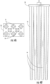
- the apparatus includes a device 15 made up of a series of vertically oriented tines 11 which extend downwardly and are fixed to a top plate 13.
- the purpose of the top plate 13 is to hold the tines 11 in place.
- the top plate 13 holds the tines together and does not necessarily provide densification or confinement during densification.
- the tines 11 are affixed to the top plate 13, with welds or other means, to achieve a mechanical attachment connection.
- the tines 11 are horizontally spaced from each other at the attachment connection on top plate 13.
- the embodiment of the top plate 13 is square with dimensions of about 30 inches (76.2 cm) on each side, and is typically three inches (7.62 cm) thick.
- the top plate 13 may be made of steel. In other embodiments, the top plate 13 could be made of other materials such as iron, concrete, or composite materials. The dimensions of the top plate 13 are selected as those appropriate to hold the tines 11 in a vertical arrangement.
- the top plate 13 is rectangular with dimensions of about 30 inches (76.2cm) wide by about 60 inches (152.4cm) long. As shown in the embodiment in Figure 4A , the top plate 13 is rectangular with dimensions of about 30 inches wide (76.2cm) by about 45 inches (114.3cm) long. The precise dimensions of the top plate 13 are selected depending on the tine arrangement desired.
- Each tine 11 extends vertically downward from the top plate 13. As shown in the embodiment shown in Figures 1 and 2B (and described in the Examples below), the tines 11 are typically five inches (12.7cm) square at the bottom transitioning to eight inches (20.32cm) square at the top, and extend a length of about six feet (1.8288m) below the bottom of top plate 13 (a taper angle of approximately 2.4°). In this embodiment, the tines 11 are tapered to facilitate easy driving and extraction. The tapered shape also serves to confine the soil vertically from upward heaving. The degree of taper angle may vary but is contemplated to typically be in the range of 0 to 5°, and preferably 0.5° to 2.5°. While these angle ranges are for illustrative purposes, it is understood that other angle ranges could be used in order to achieve displacement of soil downward and radially outward to rigidify vertical soil boundaries between adjacent tines during the densification process.
- tines 11 typically four inches (10.16cm) square at the bottom transitioning to eight inches (20.32cm) square at the top, and extending a length of about 10 feet (3.048m) below the bottom of top plate 13 (a taper angle of approximately 1.9°).
- tines 11 typically four inches (10.16cm) square at the bottom (which is 20 feet (6.096m) below the top plate) transitioning to eight inches (20.32cm) square at a distance of 10 feet (3.048m) below the top plate and remaining 8 inches (20.32cm) square from the mid-height to the top plate 13 (or the taper may be consistent from the bottom to the top, with an appropriate change in geometry or taper angle).
- each individual tine 11 of the present invention is important to ensure adequate densification to design depths for spread footings (as opposed to shallow treatment depths such as those needed for improvement below pavements, as taught in the prior art).
- the tines associated with Figures 2A and 2B tine length of six feet (1.8288m) and transitioning from five inches (12.7cm) wide at the bottom to eight inches (20.32cm) wide at the top would have a length to width ratio ranging from 9 to 14.5 (measured from the top width and the bottom width, respectively).
- the tines associated with Figures 3A and 3B (tine length of 10 feet (3.048m) and transitioning from four inches (10.16cm) wide at the bottom to eight inches (20.32cm) wide at the top) would have a length to width ratio ranging from 15 to 30 (measured from the top width and the bottom width, respectively).
- the tines associated with Figures 4A and 4B (tine length of 20 feet (6.096m) and transitioning from four inches (10.16cm) wide at the bottom to eight inches (20.32cm) wide at the top) would have a length to width ratio ranging from 30 to 60 (measured from the top width and the bottom width, respectively).
- the tines may be cylindrical.
- the tines 11 may be alternatively tapered or cylindrical.
- the tines 11 may have a bulbous bottom head 18 for additional densification as shown in Figures 5A and 5B .
- the tines 11 may be circular or may be articulated, such as octagonal, hexagonal, square, triangular, or another articulated or semi-articulated shape.
- the tines 11 are typically made of steel, cast iron, other ferrous metal, or composite materials and are typically hollow (thereby contributing to the relatively lightweight nature of the device).
- the tines 11 and top plate 13 making up the device 15 should be both strong and lightweight for easy driving.
- the device 15 is driven into the ground or soil by a mechanical driving apparatus or hammer 17 as shown in Figure 1 . Accordingly, it is important that the device be constructed in a manner that is relatively lightweight to facilitate driving.
- Typical weights for the device 15 can range from 1000 to 5000 pounds (453.592 to 2267.962kg). This is in contrast to the prior art, particularly the "deep dynamic compaction" devices previously discussed, which must be heavily weighted for proper functioning.
- the device 15 is driven into the ground using the driving apparatus 17 which can include a high-frequency piling hammer attached to a machine such as an excavator 16.
- the hammer may be a vibratory hammer typically used for sheet pile driving.
- the hammer may be a drop hammer or a diesel or air hammer such as used to drive driven displacement piles.
- Other impact devices, vibratory or nonvibratory, are also envisioned.
- the top plate 13 can include a grab plate (not shown) at the surface thereof facing the driving apparatus 17.
- the grab plate is conventional in nature and allows the top plate 13 to be attached to the driving device 17.
- the driving of the tines 11 is performed in a smooth, vibrating or hammering manner. This is in contrast to "deep dynamic compaction" devices previously discussed which require dropping a heavily weighted device from a relatively great height at intermittent intervals required for the lifting of heavy weights.
- a sensor device may optionally be used for measurement of the degree of densification during the process.
- a sensor 101 may be attached to the driving device 17 above the top plate 13 of the multi-tined device 15 (such as, for example, at a location on a hammer sled).
- the sensor would enable measurement of applied downward "crowd" pressure during the densification process.
- the sensor could consist of a pressure gage mounted on the hydraulic lines of the rig, a strain gage mounted on the hammer sled or pull down cable, or an instrumented pin that measures shear force applied to a connection. The sensor would serve as an indicator of when the design densification level has been reached.
- the tines 11 are used as conduits for the placement of flowable fill such as grout or other flowable substance.
- the tips of the tines 11 may be fitted with mechanical valves, such as shown in Figures 6A and 6B , to prevent the inward intrusion of soil below the tines during penetration and to allow the outward flow of backfill through the tines during extraction.
- Backfill materials may consist of fluid mixtures such as grout, concrete, and other self binding and hardening fluids or may consist of mixes of sand, cement, flyash, and other admixtures.
- Valves may consist of portals such as shown in Figure 6A wherein a flat plate 22 is secured by, for example, a wire rope or U-bolt 24 over a pin 26 that spans between walls of the tine 11.
- Valves may also consist of mechanical doors such as the hinged valve shown in Figure 6B which consists of a flat plate 22 hingedly attached to the body of the tine 11 by a hinge 28.
- the operation of any envisioned valve would allow the valve to remained closed (to prevent soil intrusion) as the tines are being inserted into the ground surface (due to upward force from the ground keeping the valve/hinge closed tight against the body of the tine) and as the tines are lifted up, the downward movement of the fill material will cause the valve to open to allow the fill material to flow from within the tines.
- sacrificial plates such as plate 32 at the bottom of tine 11 shown in Figure 7 may be used in lieu of valves and would function the same way operationally.
- the device 15 facilitates soil improvement to a depth greater than the furthest extension of the tines 11 in the soil. This is significant because the invention provides a means to treat the soil to depths much greater than provided by other means.
- a method in accordance with the invention involves driving the device 15 and its tines 11 into the ground to a depth of desired improvement.
- the driving takes place as quickly as possible in one smooth motion facilitated by vibratory or impact energy such as that achieved by hammering.
- the device is then retracted from the ground to the ground surface.
- the sidewalls of formed holes may collapse if the matrix soil is in a very loose state. This collapse manifests itself into settlement of the ground surface in the area of ground improvement by the device 15.
- the device 15 and its tines 11 may be then reinserted into the ground to the depth desired, and then once again retracted.
- the process of penetration and retraction serves to achieve densification through the displacement of the ground material downward and radially outward.
- the ground may "tighten up" and the holes formed by the tines 11 may stay open.
- these holes may be filled with flowable material, such as, for example, crushed limestone, sand, aggregate, gravel, granular waste products, tire chips, concrete, grout, fly ash, lime, cement, recycled materials (concrete, glass, etc.), or other flowable material.
- the purpose of the backfill is to prevent the holes from collapsing at a later time.
- the area of improvement may then be once again improved by re-inserting the device 15 and its tines 11, or it may be considered to be fully treated, depending on design requirements.
- the presence of the plurality of vertical tines 11 serves an important function for the device 15. As each tine 11 is inserted, the soil in the area of the tines 11 is displaced both downward and radially outward. The radial outward displacement is called cavity expansion. During tine 11 insertion, cavity expansion causes the soil around the tine 11 to displace outward and compact. The degree of densification depends on the ability of the soil to drain and compact, on the degree of cavity expansion, and on the boundary conditions surrounding the cavity.
- the boundary of an expanded cavity at any radius from the edge of the cavity consists of soil that itself may further deform outwardly away from the single tine.
- This non-rigid boundary lessens the amount of potential densification because it provides little lateral restraint.
- the boundary of the expanded cavity around each tine 11 is characterized in part by the presence of, and interaction with, adjacent tines 11, that are also causing cavity expansion.
- the cavity expansion of each tine 11 is contained by an adjacent expanding cavity that is being expanded in the opposite direction.
- the method described herein contemplates various steps including multiple passes then filling; filling after each pass; never filling in soils that collapse; surface tamping later; filling with sand; filling with crushed stone; filling with other aggregate; filling with gravel; filling with granular media such as glass, recycled materials, or others; filling with tire chips; filling with a fluid media such as grout or concrete; filling with mixtures of sand, water, fly ash, and cement; or using two tines, three tines, four tines, five tines, or additional tines, as may appropriate to the site.
- testing was performed using a first embodiment of the invention at an Iowa Test Site.
- the device was used to stabilize natural sand, natural silty sand, and imported fill sand at the site.
- the device 15 of the invention was advanced at a total of 36 locations.
- the device 15 was advanced to a depth of 6 feet (1.8288) in all cases. This testing program was used to evaluate the quantitative improvements using the device 15, in comparison to surface compaction with a vibratory plate applied at the ground surface.
- the device used in this Example I was fabricated to reflect the features shown in Figures 2A and 2B .
- five 6-foot (1.8288m) long tines 11 were welded to a top plate 13.
- the tines 11 were fabricated using a square cross-sectional shape tapered upward from a width of 5 inches (12.7cm) at the bottom of the tines, to a width of 8 inches (20.32cm) at the top of the tines 11.
- the tines 11 were welded to a 30-inch (76.2cm) square top plate 13.
- the tines 11 at the perimeter or periphery of the plate 13 were oriented 45 degrees relative to a central tine 19 to reduce the potential for plugging of soil/sand between adjacent tines.
- a grab plate (not shown), as previously discussed, was attached to the upper surface of the plate 13.
- a high frequency hammer that is often used for driving sheet piles was used to advance the device 15 into the soil. The hammer was attached to the device 15 by clamping to the grab plate.
- the Test Site contained approximately 4 feet (1.2192m) of natural silty sand over natural clean sand.
- Standard Penetration Test (“SPT") N-values in the upper 10 feet (3.048m) generally ranged between 5 and 10 blows per foot (0.3048m).
- Groundwater was noted at a depth of 6 to 8 feet (1.8288 to 2.4384m) during the post-installation Cone Penetration Test (“CPT”) measurements.
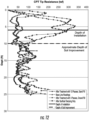
- CPT Cone Penetration Tests
- CPT tip resistances increased up to 250 tsf (23940kNm -2 ) at a depth of 3 feet (0.19144m) and ranged between about 50 tsf (4788kNm -2 ) and 150 tsf (14364kNm -2 ) below.
- the baseline CPT tip resistances ranged between 20 tsf and 80 tsf (1915kNm -2 and 7661kNm -2 ).
- Superficial compaction with vibrating plate only showed improvement to a depth of about 3 feet to 5 feet (0.9144m to 1.524m), increasing the CPT tip resistances up to 175 tsf (16758kNm -2 ) at a depth of 1 foot (0.3048m) and up to 50 tsf (4788 kNm -2 ) below.
- the soil improvement using the device of the present invention applied to both the imported sand backfill and natural silty sand over clean sand sites showed 5- to 7-fold increases in CPT tip resistances over the depth of tine penetration.
- the soils below the maximum penetration of the tines showed 1.5- to 3-fold increases in CPT tip resistances to depths of twice the width of the top plate extending below the maximum tine penetration depth.
- Example II In July of 2009, additional installations and testing were performed at the Iowa Test Site as described in Example I above.
- An alternate embodiment of the device 15 was advanced at a total of 22 locations, as described below. The device was advanced to a depth of 10 feet (3.048m) in all cases.
- FIG. 3A and 3B The embodiment used in this Example II is shown in Figures 3A and 3B and is a device having eleven individual tines 11 attached to an approximately 30-inch by 60-inch (76.2cm by 152.4cm) top plate 13, with eight tines 11 spaced from each other along the periphery of the top plate 13 and three central tines 19 spaced from each other in an interior region of top plate 13.
- a grab plate (not shown) was welded to the top plate, allowing use with a vibratory hammer (amongst others).
- Each of the tines was 10 feet (3.048m) long, with a 4-inch by 4-inch (10.16cm by 10.16cm) square bottom transitioning to an 8-inch by 8-inch (20.32cm by 20.32cm) square top where they connected to the top plate 13.
- the perimeter or periphery tines 11 were oriented 45 degrees to the central tines 19 to reduce the potential for plugging of soil/sand between adjacent tines 11 (including central tines 19).
- the installations with the embodiment of this example included four passes (insert tines, then retract and backfill holes in subsided area) and 12 passes in the imported sand site, and four passes and six passes in the natural silty sand site.
- sand backfill was used in all cases.
- the subsided area was filled with about 5 to 7 cubic yards of sand for each location. The treatment took about 2 minutes per pass. After the passes were completed the ground surface was surface compacted with a vibratory plate.
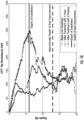
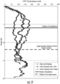
- Figure 13 shows the CPT tip resistances in the imported sand site and Figure 14 shows the CPT tip resistances for the natural silty sand site.
- the baseline CPT tip resistances generally ranged between 50 tsf and 100 tsf (4788 kNm -2 and 9576 kNm -2 ) throughout the upper 15 feet (4.572) of the soil profile.
- the CPT tip resistances increased up to about 170 tsf (16279 kNm -2 ) to a depth of 5 feet (1.524m), and ranged between 50 tsf and 150 tsf (4788 kNm -2 and 14364 kNm -2 ) from 5 feet to 10 feet (1.524m to 3.048m).
- the CPT tip resistance ranged between about 30 tsf and 120 tsf (2872 kNm -2 and 11491 kNm -2 ). After treatment with 12 passes, the CPT tip resistances showed substantially more improvement; the tip resistances increased to values up to 240 tsf (22983 kNm -2 ) at depths of 5 feet and 7 feet (1.524m to 2.1336m); and values generally ranging between 100 tsf and 150 tsf (9576 kNm -2 and 14364 kNm -2 ) from 7 feet to 13 feet (2.1336m to 3.9624m) which appeared to be the depth of soil improvement.
- the baseline CPT tip resistances generally ranged between 40 tsf and 70 tsf (3830kNm -2 and 6703kNm -2 ) to a depth of 10 feet (3.048m) and generally ranged between 60 tsf and 110 tsf (57446kNm -2 and 10534kNm -2 ) from 10 to 15 feet (3.048m to 4.572m).
- the CPT tip resistance values After treatment with four passes, the CPT tip resistance values increased to values of up to 100 tsf (9576kNm -2 ) in the upper 10 feet (3.048m) and exceeding 150 tsf (14364kNm -2 ) from 10 feet to 12 feet (3.048m to 3.6576m).
- the tip resistances ranged between 100 tsf and 150 tsf (9576 kNm -2 and 14364 kNm -2 ) from depths of 12 feet to 15 feet (3.6576m to 4.572m).
- the CPT tip resistances showed substantial improvement with tip resistance values of up to 270 tsf (25855kNm -2 ) to depths of 10 feet (3.048m) and ranging between 100 tsf and 180 tsf (9576kNm -2 and 17237kNm -2 ) from 10 feet to 15 feet (3.048m to 4.572m).
- test results made after installations with the 10 foot (3.048m) long device 15 showed significant improvements throughout the depth of device penetration and further soil improvements to about twice the width of the top plate (13) of the device extending below the maximum penetration depth.
- the degree of soil improvement increases with the number of passes.
- the device was fabricated to increase the tine length to 20 feet (6.096m) for a separate embodiment as described below.
- the new embodiment in this Example III was a device 15 including eight individual tines 11 attached to an approximately 30-inch by 45-inch (76.2cm by 114.3cm) top plate 13 as shown in Figures 4A and 4B .
- the individual tines 11 were each 20 feet (6.096m) long, with a 4-inch by 4-inch (10.16cm by 10.16cm) square bottom transitioning to an 8-inch by 8-inch (20.32cm by 20.32cm) square top where they connect to the top plate 13. The transition was accomplished approximately half-way up the tine length.
- a grab plate was welded to the top plate, allowing use with a vibratory hammer.
- the perimeter tines 11 were oriented 45 degrees to any central tines 19 to reduce the potential for plugging of soil/sand between adjacent tines 11.
- CPT testing was performed at the locations tested to quantify the improvement that was achieved.
- the first CPT attempt at the center of the four installations with the 8-tines encountered refusal at a depth of 5 feet (1.524m).
- the next CPT attempt encountered refusal at a depth of 10 feet (13.048m).
- the baseline CPT readings showed tip resistances of approximately 20 tsf (11915 kNm -2 ) to a depth of 5 feet (1.524m), approximately 50 tsf to 100 tsf (4788 kNm -2 to 9576 kNm -2 ) from 5 feet to 20 feet (1.524m to 6.096m), and approximately 70 tsf to 150 tsf (6703 kNm -2 to 14364 kNm -2 )from 20 feet to 30 feet (3.096m to 9.144m).
- the CPT tip resistance values increased with depth from about 25 tsf (2394 kNm -2 ) at one foot (0.3048m) to 200 tsf (19152 kNm -2 ) at depths of 10 to 15 feet (3.048m to4.572m).
- the tip resistances were greater than 300 tsf (28728 kNm -2 ) at depths of 15 feet to 20 feet (4.572m to6.096m) and then decreased back to the baseline readings at about 25 feet (7.62m).
- test results showed significant soil improvement throughout the depth of installation and substantial improvement to a depth of about twice the width of the top plate 13 below the bottom of the maximum penetration depth of 20 feet (6.096m). Increased soil improvement occurred with increasing number of passes.
- the device 15 used was similar to that described above with reference to Example I and shown in Figure 2A and 2B .
- the general procedure consisted of penetrating the tines to full length or a portion of the tine length, followed by retraction and backfilling with native sand. Each pass took approximately 1 ⁇ 2 minute to 1 minute to accomplish. Each set of 3 passes typically took about 4 minutes. The device sometimes achieved a penetration depth of only 1 to 4 feet (0.3048m to 1.2192m) during the third pass. Fine sand was used to backfill the cavities in all passes. Installations proceeded from one edge of the tank to the other.
- test site locations were in the general vicinity of the initial borings performed prior to construction.
- the tests were performed at installation locations and between adjacent installations.
- One CPT was performed outside the perimeter of the tank to serve as a baseline reading.
- test site location number 8 At all of the test site locations, excluding test site location number 8, the ground surface was compacted with three passes of a vibratory drum roller after the installations.
- Figure 16 presents the results of the baseline CPT readings and the CPT tip resistances at the installation locations.
- the baseline CPT tip resistances generally ranged from approximately 50 tsf to 100 tsf (4788 kNm -2 to 9576 kNm -2 ) with an average tip resistance of about 70 tsf (6703 kNm -2 ) between depths of one to 14 feet (4.2672m) below grade.
- CPT tip resistances within the footprint of the device installations are also shown on Figure 16 . Significant improvements were observed both in the reinforced zone and below the bottom of the tines to a depth of approximately 13 feet (3.9624m) below grade. After treatment with one pass, CPT tip resistances remained near the baseline readings to a depth of about 5 feet (1.524m) but then increased to values exceeding 150 tsf (14364 kNm -2 ) between depths of 6 feet and 9 feet (1.8288m and 2.7432m). The tip resistances ranged between 100 tsf and 150 tsf (9576 kNm -2 and 14364 kNm -2 ) between depths of 9 feet and 13 feet (2.7432m and 3.9624m) below grade.
- the CPT tip resistances in the upper 5 feet increased to values of up to and exceeding 250 tsf (23940 kNm -2 ) and increased to values ranging between 130 tsf and 300 tsf (12449 kNm -2 and 28728 kNm -2 ) between a depth of 5 feet and 13 feet (1.524m and 3.9624m). No increase in tip resistance was observed in the upper 2 feet (0.6096m) likely because there is insufficient surface confinement for densification.
- Figure 17 presents the results of the CPT tip resistance obtained between installation locations.
- the CPT soundings were advanced at the midpoint between installation locations 3.5 feet (1.0668m) from the center of the adjacent elements or 2.25 feet (0.6858m) from the edge of the installation locations.
- the results indicate improvement in density evidenced by increase in tip resistance from installation.
- the tip resistance values increase to values ranging between 100 tsf and 150 tsf (9576 kNm -2 and14364 kNm -2 ) at depths ranging between 2 and 10 feet (0.6096m and 3.048m).
- the tip resistances increase to values exceeding 150 tsf (14364 kNm -2 ) at depths ranging between 4 and 10 feet (1.2192m and 3.048m) below grade.
- Installations with the device of this example increase the tip resistance within the reinforced zone and below the reinforced zone, extending to a depth of up to 13 feet (3.9624m), 7 feet (2.1336m) below the bottom of the maximum tine depth. This depth of improvement is greater than twice the width of the top plate 13.
- the device In clean sand, the device increases the tip resistance values between adjacent compaction points. The increase is, on average, two times the tip resistance for unreinforced conditions at an installation spacing of 7 feet (2.1336m) on center.
- the device In clean sand, the device increases the tip resistance values within the treatment footprint to up to about 250 tsf (23940 kNm -2 ) or 2 to 4 times the tip resistance for unreinforced conditions. Improvement within and below the reinforced zone, and between adjacent installation occurs from the first device penetration and increases with successive passes.
Landscapes
- Engineering & Computer Science (AREA)
- Structural Engineering (AREA)
- Life Sciences & Earth Sciences (AREA)
- Paleontology (AREA)
- General Engineering & Computer Science (AREA)
- Environmental & Geological Engineering (AREA)
- General Life Sciences & Earth Sciences (AREA)
- Mining & Mineral Resources (AREA)
- Agronomy & Crop Science (AREA)
- Civil Engineering (AREA)
- Soil Sciences (AREA)
- Consolidation Of Soil By Introduction Of Solidifying Substances Into Soil (AREA)
- Investigation Of Foundation Soil And Reinforcement Of Foundation Soil By Compacting Or Drainage (AREA)
- Placing Or Removing Of Piles Or Sheet Piles, Or Accessories Thereof (AREA)
- Soil Working Implements (AREA)
- Paper (AREA)
- Purification Treatments By Anaerobic Or Anaerobic And Aerobic Bacteria Or Animals (AREA)
- Foundations (AREA)
- Earth Drilling (AREA)
Claims (19)
- Vorrichtung (15) zur Bodenverbesserung von Erdboden vor Belastung von einer Struktur, umfassend:(a) eine Deckplatte (13), die eine erste Oberfläche aufweist, die konfiguriert ist, damit eine Antriebsvorrichtung daran angebracht werden kann, um einen Aufprall darauf bereitzustellen;(b) eine Vielzahl von sich vertikal erstreckenden Zinken (11), die starr an einer zweiten Oberfläche der Deckplatte gegenüber der ersten Oberfläche der Deckplatte angebracht sind und an ihren oberen Seitenkanten horizontal voneinander beabstandet sind, um als Reaktion auf den von der Antriebsvorrichtung erzeugten Stoß in eine Bodenoberfläche getrieben zu werden; und(c) wobei die Zinken (11) auf eine Weise geformt, beabstandet und in Bezug aufeinander ausgerichtet sind, um eine Verschiebung des Bodenmaterials nach unten und radial nach außen zu erreichen, wobei die Zinken (11) in einem Winkel in dem Bereich von 0,5° bis 5° verjüngt sind und wobei die Zinken (11) ein Verhältnis von Länge zu Breite von 9 bis 14,5, 15 bis 30 oder 30 bis 60 aufweisen.
- Vorrichtung (15) nach Anspruch 1, wobei die Zinken (11) verjüngt sind, sodass sie an einem von der Deckplatte (13) entfernten Ende schmaler sind als an der Anbringung an der zweiten Oberfläche der Deckplatte (13).
- Vorrichtung (15) nach Anspruch 2, wobei die Zinken (11) in einem Winkel in dem Bereich von 0,5° bis 2,5° verjüngt sind.
- Vorrichtung (15) nach Anspruch 1, wobei die Zinken (11) eine Länge in dem Bereich von 0,6096 Metern bis 9,144 Metern (2 - 30 Fuß) aufweisen.
- Vorrichtung (15) nach Anspruch 1, wobei die Zinken (11) im Querschnitt kreisförmig oder gelenkig sind.
- Vorrichtung (15) nach Anspruch 1, wobei die Zinken (11) an einem von der Deckplatte (13) entfernten Ende im Wesentlichen flach sind oder an einem von der Deckplatte (13) entfernten Ende eine bauchige Form aufweisen.
- Vorrichtung (15) nach Anspruch 1, wobei die Zinken (11) aus Eisenmaterial, Stahl oder Verbundwerkstoff gefertigt sind.
- Vorrichtung (15) nach Anspruch 1, wobei die Zinken (11) hohl sind.
- Vorrichtung (15) nach Anspruch 8, wobei die Zinken (11) an den von der Deckplatte (13) entfernten Enden Öffnungen und entsprechende Ventile an den Öffnungen aufweisen, um das Eindringen von Erde während eines Vorschubs zu begrenzen und während des Zurückziehens einen Durchgang von fließfähigem Material nach außen zu ermöglichen.
- Vorrichtung (15) nach Anspruch 8, wobei die Zinken (11) jeweils an den von der Deckplatte (13) entfernten Enden Öffnungen und an den Öffnungen jeweilige Opferplatten (32) aufweisen.
- Vorrichtung (15) nach Anspruch 1, wobei die Vielzahl von Zinken (11) entweder:(a) fünf horizontal voneinander beabstandete Zinken (11) umfasst, wobei vier Umfangszinken (11) um den Umfang der Deckplatte (13) beabstandet sind und einen mittig befindlichen Zinken (19) umgeben; oder(b) elf horizontal voneinander beabstandete Zinken (11) umfasst, wobei acht Umfangszinken (11) um den Umfang der Deckplatte (13) beabstandet sind und drei mittig befindliche Zinken (19) umgeben.
- Vorrichtung (15) nach Anspruch 11, wobei die vier Umfangszinken oder die acht Umfangszinken in einem Winkel von 45° um ihre vertikale Achse in Bezug auf die mittig befindlichen Zinken (19) ausgerichtet sind.
- Verfahren zur Bodenverbesserung von Erdboden vor Belastung von einer Struktur, umfassend:(a) Bereitstellen einer Vorrichtung (15) nach einem der Ansprüche 1 bis 7, 11 oder 12;(b) Vorschieben der Vorrichtungszinken (11) in die Bodenoberfläche;(c) Zurückziehen der Zinken (11) aus der Bodenoberfläche; und(d) Wiederholen des Vorschiebens und Zurückziehens, bis der gewünschte Bodenzustand erreicht ist.
- Verfahren nach Anspruch 13, wobei die Vorrichtung (15) eine Vorrichtung nach Anspruch 1 ist, wobei das Vorschieben der Zinken (11) an der Stelle, an der die Zinken (11) vorgeschoben werden, Hohlräume erzeugt, und wobei ferner Auffüllmaterial in die Hohlräume eingebracht wird und die Vorrichtung wiederholt vorgeschoben und zurückgezogen wird, nachdem das Auffüllmaterial hinzugefügt worden ist.
- Verfahren nach Anspruch 14, wobei die Zinken (11) hohl sind und jeweils eine Öffnung an einem von der Oberflächenplatte (13) entfernten Ende aufweisen, und ferner umfassend ein Hinzufügen von Auffüllmaterial durch die Zinken (11) und aus der Öffnung von jedem Zinken (11) bei dessen Zurückziehen.
- Verfahren nach Anspruch 15, wobei entweder:(a) die Zinken (11) an den offenen Enden entsprechende Ventile aufweisen, und umfassend ein Geschlossenhalten der Ventile beim Vorschieben der Vorrichtung (15) und Öffnen der Ventile beim Zurückziehen und Hinzufügen des Auffüllmaterials durch die Zinken (11); oder(b) die Zinken (11) jeweilige Opferplatten (32) an den offenen Enden aufweisen, und umfassend ein Befestigen der Opferplatten (32) an den Zinken (11) beim Vorschieben der Vorrichtung (15) und ein Zulassen, dass sich die Opferplatten (32) beim Zurückziehen von den Zinken (11) trennen, und ein Hinzufügen des Auffüllmaterials durch die Zinken (11).
- Verfahren nach Anspruch 14, wobei das Auffüllmaterial eines oder eine Kombination von Schotter, Sand, Zuschlagstoffen, Kies, Mörtel, Beton, Kalk, Flugasche, Abfallstoffen, Reifenschnitzeln, recycelten Materialien und anderen fließfähigen Stoffen ist.
- Verfahren nach Anspruch 13, wobei die Vorrichtung (15) eine Vorrichtung (15) nach Anspruch 1 ist, wobei der erreichte Grad der Bodenverbesserung durch eine Überwachung des Abwärtsdrucks während des Eindringens zum Bestimmen des Verdichtungsgrads gemessen wird.
- Verfahren nach Anspruch 13, wobei das Verfahren, nachdem der gewünschte Bodenzustand erreicht ist, ferner den Schritt eines Hinzufügens eines Pfahls, eines Betonpfeilers, eines Gebäudes, einer Platte, einer Wand, eines Tanks, einer Transportstruktur, eines Industriewerks oder einer anderen Struktur auf dem Boden umfasst.
Applications Claiming Priority (2)
| Application Number | Priority Date | Filing Date | Title |
|---|---|---|---|
| US21981409P | 2009-06-24 | 2009-06-24 | |
| PCT/US2010/037032 WO2011005386A2 (en) | 2009-06-24 | 2010-06-02 | Apparatus and method for ground improvement |
Publications (3)
| Publication Number | Publication Date |
|---|---|
| EP2446089A2 EP2446089A2 (de) | 2012-05-02 |
| EP2446089A4 EP2446089A4 (de) | 2015-11-11 |
| EP2446089B1 true EP2446089B1 (de) | 2023-04-19 |
Family
ID=43380931
Family Applications (1)
| Application Number | Title | Priority Date | Filing Date |
|---|---|---|---|
| EP10797500.5A Active EP2446089B1 (de) | 2009-06-24 | 2010-06-02 | Vorrichtung und verfahren zur bodenverbesserung |
Country Status (18)
| Country | Link |
|---|---|
| US (1) | US8360689B2 (de) |
| EP (1) | EP2446089B1 (de) |
| AU (1) | AU2010271068B2 (de) |
| BR (1) | BRPI1009653A2 (de) |
| CA (1) | CA2765947C (de) |
| CL (1) | CL2011003267A1 (de) |
| CO (1) | CO6491047A2 (de) |
| CR (1) | CR20120034A (de) |
| EC (1) | ECSP11011549A (de) |
| EG (1) | EG26586A (de) |
| ES (1) | ES2949569T3 (de) |
| IN (1) | IN2012DN00323A (de) |
| MA (1) | MA33383B1 (de) |
| MX (1) | MX2012000195A (de) |
| NZ (1) | NZ597540A (de) |
| PE (1) | PE20120786A1 (de) |
| RU (1) | RU2011153113A (de) |
| WO (1) | WO2011005386A2 (de) |
Families Citing this family (6)
| Publication number | Priority date | Publication date | Assignee | Title |
|---|---|---|---|---|
| US9091035B2 (en) * | 2012-09-05 | 2015-07-28 | Dewind One-Pass Trenching, Llc | System and method of forming an underground slurry wall |
| US9702108B2 (en) * | 2015-05-28 | 2017-07-11 | JAFEC USA, Inc. | Direct power compaction method |
| CN109295967A (zh) * | 2018-10-23 | 2019-02-01 | 中国水利水电第四工程局有限公司 | 一种5000千牛顿米能级强夯方法 |
| CN110284484B (zh) * | 2019-07-02 | 2020-11-10 | 江苏东交工程检测股份有限公司 | 压实度预测方法、装置、设备及存储介质 |
| US11708678B2 (en) | 2019-12-18 | 2023-07-25 | Cyntech Anchors Ltd | Systems and methods for supporting a structure upon compressible soil |
| US11952736B2 (en) * | 2021-08-31 | 2024-04-09 | Geopier Foundation Company, Inc. | System and method for installing an aggregate pier |
Citations (4)
| Publication number | Priority date | Publication date | Assignee | Title |
|---|---|---|---|---|
| FR2482155A1 (fr) * | 1980-05-08 | 1981-11-13 | Routes Chemins Fer Canaux | Procede de stabilisation de sol par introduction de produits solidifiants et machine destinee a mettre en oeuvre ledit procede |
| EP0672794A1 (de) * | 1994-03-16 | 1995-09-20 | Terramix KG Schotterproduktions-Süd-GmbH & Co. | Tiefenverdichter |
| RU2116193C1 (ru) * | 1995-11-01 | 1998-07-27 | Николай Григорьевич Емельяненко | Агрегат для глубинной виброобработки материалов |
| CN2786200Y (zh) * | 2005-04-13 | 2006-06-07 | 国家电力公司华东勘测设计研究院 | 多头加气振冲装置 |
Family Cites Families (19)
| Publication number | Priority date | Publication date | Assignee | Title |
|---|---|---|---|---|
| US794971A (en) * | 1904-02-23 | 1905-07-18 | Henry Ericsson | Foundation. |
| NL8701654A (nl) | 1987-07-14 | 1989-02-01 | Ballast Nedam Groep Nv | Werkwijze en inrichting voor het verdichten van grond. |
| GB8807276D0 (en) * | 1988-03-26 | 1988-04-27 | Chemrock Cryogenic Corp | Settling/compacting granular material |
| US5249892A (en) | 1991-03-20 | 1993-10-05 | Fox Nathaniel S | Short aggregate piers and method and apparatus for producing same |
| EP0514559B1 (de) | 1991-05-17 | 1995-03-01 | Kurt Ellmer | Übertragung der Last eines Gebäudes über Stahlträger auf das Umland durch den Einsatz eines Spezialfallbären |
| US5152348A (en) * | 1991-08-05 | 1992-10-06 | Flanagan Sr Robert P | Turf aerating machine and tool attachment |
| GB2286613B (en) * | 1994-02-18 | 1998-05-13 | Roxbury Ltd | Improvements in or relating to methods and apparatus for improving the condition of ground |
| JPH08296252A (ja) * | 1995-04-26 | 1996-11-12 | Takenaka Komuten Co Ltd | 削孔機の押し込み装置と押し込み方法 |
| ATE207168T1 (de) * | 1995-07-31 | 2001-11-15 | Helmut Hemmerlein Gmbh & Co Ba | Verfahren zur einbringung von sich verjüngenden pfählen, zugehörige pfähle, und daraus hergestellte gründungen und fundamentbildungen |
| GB2345509B (en) | 1997-08-20 | 2002-05-08 | Roxbury Ltd | Ground treatment |
| US6354766B1 (en) | 1999-02-09 | 2002-03-12 | Geotechnical Reinforcement Company, Inc. | Methods for forming a short aggregate pier and a product formed from said methods |
| JP2001140247A (ja) * | 1999-11-12 | 2001-05-22 | Shohei Senda | 地盤改良装置 |
| WO2001096669A1 (en) | 2000-06-15 | 2001-12-20 | Geotechnical Reinforcement Company, Inc. | Lateral displacement pier and method of installing the same |
| US7226246B2 (en) | 2000-06-15 | 2007-06-05 | Geotechnical Reinforcement, Inc. | Apparatus and method for building support piers from one or successive lifts formed in a soil matrix |
| JP3458275B2 (ja) * | 2001-03-16 | 2003-10-20 | 昇 工藤 | 軟弱地盤上の盛土安定工法 |
| US20050274532A1 (en) * | 2004-06-01 | 2005-12-15 | Kevin Lephart | Ground improvement device |
| US7326004B2 (en) * | 2004-10-27 | 2008-02-05 | Geopier Foundation Company, Inc. | Apparatus for providing a rammed aggregate pier |
| JP2008121401A (ja) * | 2006-11-14 | 2008-05-29 | Shigekazu Hanzawa | 地盤改良型減震装置 |
| KR20090122963A (ko) | 2007-02-22 | 2009-12-01 | 지오피어 파운데이션 컴파니, 인코포레이티드 | 상방 유동 제한부를 가지는 중공형의 맨드렐을 이용하여 쇄석다짐말뚝을 형성하기 위한 장치 및 방법 |
-
2010
- 2010-06-02 MX MX2012000195A patent/MX2012000195A/es active IP Right Grant
- 2010-06-02 CA CA2765947A patent/CA2765947C/en active Active
- 2010-06-02 AU AU2010271068A patent/AU2010271068B2/en active Active
- 2010-06-02 WO PCT/US2010/037032 patent/WO2011005386A2/en not_active Ceased
- 2010-06-02 PE PE2011002148A patent/PE20120786A1/es active IP Right Grant
- 2010-06-02 EP EP10797500.5A patent/EP2446089B1/de active Active
- 2010-06-02 ES ES10797500T patent/ES2949569T3/es active Active
- 2010-06-02 IN IN323DEN2012 patent/IN2012DN00323A/en unknown
- 2010-06-02 BR BRPI1009653A patent/BRPI1009653A2/pt not_active Application Discontinuation
- 2010-06-02 RU RU2011153113/03A patent/RU2011153113A/ru unknown
- 2010-06-02 MA MA34485A patent/MA33383B1/fr unknown
- 2010-06-02 NZ NZ597540A patent/NZ597540A/xx unknown
- 2010-12-23 US US12/977,196 patent/US8360689B2/en active Active
-
2011
- 2011-12-19 EG EG2011122117A patent/EG26586A/en active
- 2011-12-22 EC ECSP11011549 patent/ECSP11011549A/es unknown
- 2011-12-22 CL CL2011003267A patent/CL2011003267A1/es unknown
-
2012
- 2012-01-17 CO CO12006225A patent/CO6491047A2/es active IP Right Grant
- 2012-01-18 CR CR20120034A patent/CR20120034A/es unknown
Patent Citations (4)
| Publication number | Priority date | Publication date | Assignee | Title |
|---|---|---|---|---|
| FR2482155A1 (fr) * | 1980-05-08 | 1981-11-13 | Routes Chemins Fer Canaux | Procede de stabilisation de sol par introduction de produits solidifiants et machine destinee a mettre en oeuvre ledit procede |
| EP0672794A1 (de) * | 1994-03-16 | 1995-09-20 | Terramix KG Schotterproduktions-Süd-GmbH & Co. | Tiefenverdichter |
| RU2116193C1 (ru) * | 1995-11-01 | 1998-07-27 | Николай Григорьевич Емельяненко | Агрегат для глубинной виброобработки материалов |
| CN2786200Y (zh) * | 2005-04-13 | 2006-06-07 | 国家电力公司华东勘测设计研究院 | 多头加气振冲装置 |
Also Published As
| Publication number | Publication date |
|---|---|
| EP2446089A2 (de) | 2012-05-02 |
| EP2446089A4 (de) | 2015-11-11 |
| CO6491047A2 (es) | 2012-07-31 |
| EG26586A (en) | 2014-03-17 |
| CL2011003267A1 (es) | 2012-06-22 |
| ECSP11011549A (es) | 2012-04-30 |
| US8360689B2 (en) | 2013-01-29 |
| CA2765947C (en) | 2014-08-12 |
| ES2949569T3 (es) | 2023-09-29 |
| WO2011005386A3 (en) | 2011-03-31 |
| MA33383B1 (fr) | 2012-06-01 |
| US20110091291A1 (en) | 2011-04-21 |
| CA2765947A1 (en) | 2011-01-13 |
| BRPI1009653A2 (pt) | 2018-06-19 |
| MX2012000195A (es) | 2012-08-08 |
| PE20120786A1 (es) | 2012-07-12 |
| WO2011005386A2 (en) | 2011-01-13 |
| AU2010271068B2 (en) | 2015-07-16 |
| CR20120034A (es) | 2012-05-21 |
| RU2011153113A (ru) | 2013-07-27 |
| IN2012DN00323A (de) | 2015-05-08 |
| AU2010271068A1 (en) | 2012-02-02 |
| NZ597540A (en) | 2013-04-26 |
Similar Documents
| Publication | Publication Date | Title |
|---|---|---|
| US8328470B2 (en) | Apparatus and method for ground improvement | |
| US9915050B2 (en) | Apparatus and method for ground improvement | |
| US7326004B2 (en) | Apparatus for providing a rammed aggregate pier | |
| US8221034B2 (en) | Methods of providing a support column | |
| CA2730150C (en) | Shielded tamper and method of use for making aggregate columns | |
| US10513831B2 (en) | Open-end extensible shells and related methods for constructing a support pier | |
| US8573892B2 (en) | Method of providing a support column | |
| US10941534B2 (en) | Methods and apparatuses for compacting soil and granular materials | |
| EP2446089B1 (de) | Vorrichtung und verfahren zur bodenverbesserung | |
| US12320090B2 (en) | Methods and apparatuses for compacting soil and granular materials | |
| US8740501B2 (en) | Apparatus and method for ground improvement | |
| CA2950733C (en) | Apparatus and method for ground improvement | |
| CA3210951C (en) | METHODS AND APPARATUS FOR COMPACTING SOIL AND GRANULATED MATERIALS | |
| CA2551216C (en) | Method and apparatus for providing a rammed aggregate pier |
Legal Events
| Date | Code | Title | Description |
|---|---|---|---|
| PUAI | Public reference made under article 153(3) epc to a published international application that has entered the european phase |
Free format text: ORIGINAL CODE: 0009012 |
|
| 17P | Request for examination filed |
Effective date: 20120124 |
|
| AK | Designated contracting states |
Kind code of ref document: A2 Designated state(s): AL AT BE BG CH CY CZ DE DK EE ES FI FR GB GR HR HU IE IS IT LI LT LU LV MC MK MT NL NO PL PT RO SE SI SK SM TR |
|
| AX | Request for extension of the european patent |
Extension state: BA RS |
|
| RAX | Requested extension states of the european patent have changed |
Extension state: RS Payment date: 20120124 Extension state: BA Payment date: 20120124 |
|
| A4 | Supplementary search report drawn up and despatched |
Effective date: 20151009 |
|
| RIC1 | Information provided on ipc code assigned before grant |
Ipc: E02D 3/02 20060101AFI20151005BHEP |
|
| RAP1 | Party data changed (applicant data changed or rights of an application transferred) |
Owner name: GEOPIER FOUNDATION COMPANY, INC. |
|
| STAA | Information on the status of an ep patent application or granted ep patent |
Free format text: STATUS: EXAMINATION IS IN PROGRESS |
|
| 17Q | First examination report despatched |
Effective date: 20180326 |
|
| REG | Reference to a national code |
Ref country code: DE Ref legal event code: R079 Ref document number: 602010068759 Country of ref document: DE Free format text: PREVIOUS MAIN CLASS: E02D0003020000 Ipc: E02D0003046000 |
|
| RIC1 | Information provided on ipc code assigned before grant |
Ipc: E02D 3/12 20060101ALI20220928BHEP Ipc: E02D 3/054 20060101ALI20220928BHEP Ipc: E02D 3/046 20060101AFI20220928BHEP |
|
| GRAP | Despatch of communication of intention to grant a patent |
Free format text: ORIGINAL CODE: EPIDOSNIGR1 |
|
| STAA | Information on the status of an ep patent application or granted ep patent |
Free format text: STATUS: GRANT OF PATENT IS INTENDED |
|
| INTG | Intention to grant announced |
Effective date: 20221107 |
|
| GRAS | Grant fee paid |
Free format text: ORIGINAL CODE: EPIDOSNIGR3 |
|
| GRAA | (expected) grant |
Free format text: ORIGINAL CODE: 0009210 |
|
| STAA | Information on the status of an ep patent application or granted ep patent |
Free format text: STATUS: THE PATENT HAS BEEN GRANTED |
|
| AK | Designated contracting states |
Kind code of ref document: B1 Designated state(s): AL AT BE BG CH CY CZ DE DK EE ES FI FR GB GR HR HU IE IS IT LI LT LU LV MC MK MT NL NO PL PT RO SE SI SK SM TR |
|
| REG | Reference to a national code |
Ref country code: GB Ref legal event code: FG4D |
|
| REG | Reference to a national code |
Ref country code: DE Ref legal event code: R096 Ref document number: 602010068759 Country of ref document: DE |
|
| REG | Reference to a national code |
Ref country code: CH Ref legal event code: EP |
|
| REG | Reference to a national code |
Ref country code: IE Ref legal event code: FG4D |
|
| REG | Reference to a national code |
Ref country code: AT Ref legal event code: REF Ref document number: 1561257 Country of ref document: AT Kind code of ref document: T Effective date: 20230515 |
|
| REG | Reference to a national code |
Ref country code: LT Ref legal event code: MG9D |
|
| REG | Reference to a national code |
Ref country code: NL Ref legal event code: MP Effective date: 20230419 |
|
| REG | Reference to a national code |
Ref country code: AT Ref legal event code: MK05 Ref document number: 1561257 Country of ref document: AT Kind code of ref document: T Effective date: 20230419 |
|
| PG25 | Lapsed in a contracting state [announced via postgrant information from national office to epo] |
Ref country code: NL Free format text: LAPSE BECAUSE OF FAILURE TO SUBMIT A TRANSLATION OF THE DESCRIPTION OR TO PAY THE FEE WITHIN THE PRESCRIBED TIME-LIMIT Effective date: 20230419 |
|
| REG | Reference to a national code |
Ref country code: ES Ref legal event code: FG2A Ref document number: 2949569 Country of ref document: ES Kind code of ref document: T3 Effective date: 20230929 |
|
| PG25 | Lapsed in a contracting state [announced via postgrant information from national office to epo] |
Ref country code: SE Free format text: LAPSE BECAUSE OF FAILURE TO SUBMIT A TRANSLATION OF THE DESCRIPTION OR TO PAY THE FEE WITHIN THE PRESCRIBED TIME-LIMIT Effective date: 20230419 Ref country code: PT Free format text: LAPSE BECAUSE OF FAILURE TO SUBMIT A TRANSLATION OF THE DESCRIPTION OR TO PAY THE FEE WITHIN THE PRESCRIBED TIME-LIMIT Effective date: 20230821 Ref country code: NO Free format text: LAPSE BECAUSE OF FAILURE TO SUBMIT A TRANSLATION OF THE DESCRIPTION OR TO PAY THE FEE WITHIN THE PRESCRIBED TIME-LIMIT Effective date: 20230719 Ref country code: AT Free format text: LAPSE BECAUSE OF FAILURE TO SUBMIT A TRANSLATION OF THE DESCRIPTION OR TO PAY THE FEE WITHIN THE PRESCRIBED TIME-LIMIT Effective date: 20230419 |
|
| PG25 | Lapsed in a contracting state [announced via postgrant information from national office to epo] |
Ref country code: PL Free format text: LAPSE BECAUSE OF FAILURE TO SUBMIT A TRANSLATION OF THE DESCRIPTION OR TO PAY THE FEE WITHIN THE PRESCRIBED TIME-LIMIT Effective date: 20230419 Ref country code: LV Free format text: LAPSE BECAUSE OF FAILURE TO SUBMIT A TRANSLATION OF THE DESCRIPTION OR TO PAY THE FEE WITHIN THE PRESCRIBED TIME-LIMIT Effective date: 20230419 Ref country code: LT Free format text: LAPSE BECAUSE OF FAILURE TO SUBMIT A TRANSLATION OF THE DESCRIPTION OR TO PAY THE FEE WITHIN THE PRESCRIBED TIME-LIMIT Effective date: 20230419 Ref country code: IS Free format text: LAPSE BECAUSE OF FAILURE TO SUBMIT A TRANSLATION OF THE DESCRIPTION OR TO PAY THE FEE WITHIN THE PRESCRIBED TIME-LIMIT Effective date: 20230819 Ref country code: HR Free format text: LAPSE BECAUSE OF FAILURE TO SUBMIT A TRANSLATION OF THE DESCRIPTION OR TO PAY THE FEE WITHIN THE PRESCRIBED TIME-LIMIT Effective date: 20230419 Ref country code: GR Free format text: LAPSE BECAUSE OF FAILURE TO SUBMIT A TRANSLATION OF THE DESCRIPTION OR TO PAY THE FEE WITHIN THE PRESCRIBED TIME-LIMIT Effective date: 20230720 Ref country code: AL Free format text: LAPSE BECAUSE OF FAILURE TO SUBMIT A TRANSLATION OF THE DESCRIPTION OR TO PAY THE FEE WITHIN THE PRESCRIBED TIME-LIMIT Effective date: 20230419 |
|
| PG25 | Lapsed in a contracting state [announced via postgrant information from national office to epo] |
Ref country code: FI Free format text: LAPSE BECAUSE OF FAILURE TO SUBMIT A TRANSLATION OF THE DESCRIPTION OR TO PAY THE FEE WITHIN THE PRESCRIBED TIME-LIMIT Effective date: 20230419 |
|
| PG25 | Lapsed in a contracting state [announced via postgrant information from national office to epo] |
Ref country code: SK Free format text: LAPSE BECAUSE OF FAILURE TO SUBMIT A TRANSLATION OF THE DESCRIPTION OR TO PAY THE FEE WITHIN THE PRESCRIBED TIME-LIMIT Effective date: 20230419 |
|
| PG25 | Lapsed in a contracting state [announced via postgrant information from national office to epo] |
Ref country code: MC Free format text: LAPSE BECAUSE OF FAILURE TO SUBMIT A TRANSLATION OF THE DESCRIPTION OR TO PAY THE FEE WITHIN THE PRESCRIBED TIME-LIMIT Effective date: 20230419 |
|
| REG | Reference to a national code |
Ref country code: DE Ref legal event code: R097 Ref document number: 602010068759 Country of ref document: DE |
|
| PG25 | Lapsed in a contracting state [announced via postgrant information from national office to epo] |
Ref country code: SM Free format text: LAPSE BECAUSE OF FAILURE TO SUBMIT A TRANSLATION OF THE DESCRIPTION OR TO PAY THE FEE WITHIN THE PRESCRIBED TIME-LIMIT Effective date: 20230419 Ref country code: SK Free format text: LAPSE BECAUSE OF FAILURE TO SUBMIT A TRANSLATION OF THE DESCRIPTION OR TO PAY THE FEE WITHIN THE PRESCRIBED TIME-LIMIT Effective date: 20230419 Ref country code: RO Free format text: LAPSE BECAUSE OF FAILURE TO SUBMIT A TRANSLATION OF THE DESCRIPTION OR TO PAY THE FEE WITHIN THE PRESCRIBED TIME-LIMIT Effective date: 20230419 Ref country code: MC Free format text: LAPSE BECAUSE OF FAILURE TO SUBMIT A TRANSLATION OF THE DESCRIPTION OR TO PAY THE FEE WITHIN THE PRESCRIBED TIME-LIMIT Effective date: 20230419 Ref country code: EE Free format text: LAPSE BECAUSE OF FAILURE TO SUBMIT A TRANSLATION OF THE DESCRIPTION OR TO PAY THE FEE WITHIN THE PRESCRIBED TIME-LIMIT Effective date: 20230419 Ref country code: DK Free format text: LAPSE BECAUSE OF FAILURE TO SUBMIT A TRANSLATION OF THE DESCRIPTION OR TO PAY THE FEE WITHIN THE PRESCRIBED TIME-LIMIT Effective date: 20230419 Ref country code: CZ Free format text: LAPSE BECAUSE OF FAILURE TO SUBMIT A TRANSLATION OF THE DESCRIPTION OR TO PAY THE FEE WITHIN THE PRESCRIBED TIME-LIMIT Effective date: 20230419 |
|
| REG | Reference to a national code |
Ref country code: CH Ref legal event code: PL |
|
| PLBE | No opposition filed within time limit |
Free format text: ORIGINAL CODE: 0009261 |
|
| STAA | Information on the status of an ep patent application or granted ep patent |
Free format text: STATUS: NO OPPOSITION FILED WITHIN TIME LIMIT |
|
| REG | Reference to a national code |
Ref country code: BE Ref legal event code: MM Effective date: 20230630 |
|
| PG25 | Lapsed in a contracting state [announced via postgrant information from national office to epo] |
Ref country code: LU Free format text: LAPSE BECAUSE OF NON-PAYMENT OF DUE FEES Effective date: 20230602 |
|
| 26N | No opposition filed |
Effective date: 20240122 |
|
| REG | Reference to a national code |
Ref country code: IE Ref legal event code: MM4A |
|
| PG25 | Lapsed in a contracting state [announced via postgrant information from national office to epo] |
Ref country code: LU Free format text: LAPSE BECAUSE OF NON-PAYMENT OF DUE FEES Effective date: 20230602 |
|
| PG25 | Lapsed in a contracting state [announced via postgrant information from national office to epo] |
Ref country code: IE Free format text: LAPSE BECAUSE OF NON-PAYMENT OF DUE FEES Effective date: 20230602 |
|
| PG25 | Lapsed in a contracting state [announced via postgrant information from national office to epo] |
Ref country code: IE Free format text: LAPSE BECAUSE OF NON-PAYMENT OF DUE FEES Effective date: 20230602 Ref country code: CH Free format text: LAPSE BECAUSE OF NON-PAYMENT OF DUE FEES Effective date: 20230630 |
|
| PG25 | Lapsed in a contracting state [announced via postgrant information from national office to epo] |
Ref country code: SI Free format text: LAPSE BECAUSE OF FAILURE TO SUBMIT A TRANSLATION OF THE DESCRIPTION OR TO PAY THE FEE WITHIN THE PRESCRIBED TIME-LIMIT Effective date: 20230419 |
|
| PG25 | Lapsed in a contracting state [announced via postgrant information from national office to epo] |
Ref country code: SI Free format text: LAPSE BECAUSE OF FAILURE TO SUBMIT A TRANSLATION OF THE DESCRIPTION OR TO PAY THE FEE WITHIN THE PRESCRIBED TIME-LIMIT Effective date: 20230419 Ref country code: IT Free format text: LAPSE BECAUSE OF FAILURE TO SUBMIT A TRANSLATION OF THE DESCRIPTION OR TO PAY THE FEE WITHIN THE PRESCRIBED TIME-LIMIT Effective date: 20230419 Ref country code: FR Free format text: LAPSE BECAUSE OF NON-PAYMENT OF DUE FEES Effective date: 20230619 Ref country code: BE Free format text: LAPSE BECAUSE OF NON-PAYMENT OF DUE FEES Effective date: 20230630 |
|
| PG25 | Lapsed in a contracting state [announced via postgrant information from national office to epo] |
Ref country code: BG Free format text: LAPSE BECAUSE OF FAILURE TO SUBMIT A TRANSLATION OF THE DESCRIPTION OR TO PAY THE FEE WITHIN THE PRESCRIBED TIME-LIMIT Effective date: 20230419 |
|
| PG25 | Lapsed in a contracting state [announced via postgrant information from national office to epo] |
Ref country code: BG Free format text: LAPSE BECAUSE OF FAILURE TO SUBMIT A TRANSLATION OF THE DESCRIPTION OR TO PAY THE FEE WITHIN THE PRESCRIBED TIME-LIMIT Effective date: 20230419 |
|
| PGFP | Annual fee paid to national office [announced via postgrant information from national office to epo] |
Ref country code: DE Payment date: 20250604 Year of fee payment: 16 |
|
| PGFP | Annual fee paid to national office [announced via postgrant information from national office to epo] |
Ref country code: GB Payment date: 20250605 Year of fee payment: 16 |
|
| PG25 | Lapsed in a contracting state [announced via postgrant information from national office to epo] |
Ref country code: CY Free format text: LAPSE BECAUSE OF FAILURE TO SUBMIT A TRANSLATION OF THE DESCRIPTION OR TO PAY THE FEE WITHIN THE PRESCRIBED TIME-LIMIT; INVALID AB INITIO Effective date: 20100602 |
|
| PGFP | Annual fee paid to national office [announced via postgrant information from national office to epo] |
Ref country code: TR Payment date: 20250530 Year of fee payment: 16 |
|
| PG25 | Lapsed in a contracting state [announced via postgrant information from national office to epo] |
Ref country code: HU Free format text: LAPSE BECAUSE OF FAILURE TO SUBMIT A TRANSLATION OF THE DESCRIPTION OR TO PAY THE FEE WITHIN THE PRESCRIBED TIME-LIMIT; INVALID AB INITIO Effective date: 20100602 |
|
| PGFP | Annual fee paid to national office [announced via postgrant information from national office to epo] |
Ref country code: ES Payment date: 20250704 Year of fee payment: 16 |