EP2445686B1 - Elektrischer rasierapparat - Google Patents
Elektrischer rasierapparat Download PDFInfo
- Publication number
- EP2445686B1 EP2445686B1 EP10731603.6A EP10731603A EP2445686B1 EP 2445686 B1 EP2445686 B1 EP 2445686B1 EP 10731603 A EP10731603 A EP 10731603A EP 2445686 B1 EP2445686 B1 EP 2445686B1
- Authority
- EP
- European Patent Office
- Prior art keywords
- sliding
- hair cutter
- long hair
- sliding element
- casing
- Prior art date
- Legal status (The legal status is an assumption and is not a legal conclusion. Google has not performed a legal analysis and makes no representation as to the accuracy of the status listed.)
- Active
Links
Images


Classifications
-
- B—PERFORMING OPERATIONS; TRANSPORTING
- B26—HAND CUTTING TOOLS; CUTTING; SEVERING
- B26B—HAND-HELD CUTTING TOOLS NOT OTHERWISE PROVIDED FOR
- B26B19/00—Clippers or shavers operating with a plurality of cutting edges, e.g. hair clippers, dry shavers
- B26B19/02—Clippers or shavers operating with a plurality of cutting edges, e.g. hair clippers, dry shavers of the reciprocating-cutter type
- B26B19/04—Cutting heads therefor; Cutters therefor; Securing equipment thereof
- B26B19/10—Cutting heads therefor; Cutters therefor; Securing equipment thereof involving two or more different types of reciprocating cutting elements, e.g. a pair of toothed shearing elements combined with a pair of perforated cutting elements or a combined toothed and perforated cutting assembly
- B26B19/102—Cutting heads therefor; Cutters therefor; Securing equipment thereof involving two or more different types of reciprocating cutting elements, e.g. a pair of toothed shearing elements combined with a pair of perforated cutting elements or a combined toothed and perforated cutting assembly with a secondary cutting unit being translated or slid into an operating position
Definitions
- the invention relates to an electric shaving apparatus according to the preamble of Claim 1.
- the shaving apparatuses described therein have, in addition to a short hair cutter, a long hair cutter pre-mounted in front of the short hair cutter. To be operational, the long hair cutter can be lifted out of its casing by means of a sliding switch. In the process it partially or completely covers the short hair cutter from back to front so that a better contact with the skin surface of the operator can henceforth be made, primarily when shaving.
- the electric drive mechanism of the short hair cutter is first switched on and, as the long hair cutter continues to slide, the latter is coupled with the drive mechanism by means of the transmission mechanism. This obviates the need for an additional drive for the long hair cutter.
- the transmission mechanism consists of gear racks situated both on the shaver casing and on the blade casing.
- gear racks By means of gear wheels situated on the sliding switch, the gear racks achieve a certain distance as the gears engage.
- the sliding switch is moved further along, the sliding distance of the long hair cutter increases in accordance with the gear transmission.
- a transmission mechanism for accelerating the lifting out of the long hair cutter essentially consists of a two-arm lever that can pivot around a rotating axis fixed to the casing. With the help of the lever transmission, the displacement path of the long hair cutter initiated on the sliding switch increases accordingly.
- this also applies to the electrically operated shaving apparatus according to DE 41 17 988 C2 .
- a coupling mechanism is used in which three interconnected lever arms provide for transmission to the long hair cutter.
- the coupling mechanism is designed in such a way that, first, the long hair cutter moves in a straight line when the sliding switch is activated. Only after a certain starting distance in the event of a further movement of the sliding switch does displacement to the long hair cutter take place; i.e., the displacement path to the sliding switch moves is less than that of the long hair cutter. This transmission can even reverse to a reduction if slid further.
- the problem of the invention is to avoid the above disadvantages and to design a transmission mechanism that can be made with a very simple and stable construction, while keeping the complexity of the components and the costs very low.
- the stop can be situated on the shaver casing so that the sliding switch only reaches the stop on the ramp of the sliding element after a starting distance of the sliding switch, so that the additional distance to the long hair cutter only commences after that.
- the stop is already in the starting position of the sliding switch on the ramp and already provides a greater distance to the long hair cutter during the initial movement of the sliding switch.
- Any mechanical or hydraulic variant can be used for the design of the displacement device; the only important thing is that the displacement path running perpendicular to the sliding direction of the sliding switch on the sliding element is in turn redirected in the perpendicular direction; i.e., is in turn redirected in the direction of the sliding switch on the long hair cutter.
- the displacement device consists of a second sliding element that preferably runs in the second guide path and/or is also fed into a separate, fourth guide path running parallel to the second guide path, wherein the second sliding element is in sliding contact with the first sliding element by means of sliding surfaces running aslant to the guide paths.
- the interacting sliding surfaces must therefore be arranged so that, depending on the materials of the sliding elements, dynamic friction is always formed on the sliding surfaces.
- sliding elements are plastic parts that are easily manufactured and have very low slip values.
- metallic materials having good dry-running properties are also conceivable.
- the guide path is also formed by a polygonal shaft or by walls that lend the sliding element a coercive sliding guide in only one sliding direction.
- a hole can be chosen as a guide path into which is mounted the adjustable sliding element.
- this movement is in turn deflected at a 90° angle to the second sliding element, all or one part of which is directly attached to the casing of the long hair cutter. This causes the entire long hair cutter to then be quickly removed from the shaver casing via the third guide path in the direction of the movement of the sliding switch.
- the sliding surfaces form a ramp angle of 45°.
- the sliding switch distance is doubled by means of the transmission mechanism, which then causes the long hair cutter also to travel twice the distance.
- ramp angles that maintain dynamic friction are also conceivable; the only important thing is that the operating force on the sliding switch is not too great.
- the deflection device consist of a flexible band attached to a first sliding element that is forcibly led into the third and a fourth or a fifth guide path.
- This forcible guiding is necessary so that the movement exercised by the first sliding element on the deflection device is transmitted directly onto the deflection device of the long hair cutter without shortening the distance or distorting the shape.
- Suitable as a guide path when choosing the deflection device as a flexible or otherwise rigid band is a groove arrangement adjusted to the band in a cross section in which the band can be moved free of play.
- the deflection device is acted upon by a return spring.
- This return spring preferably attaches, on the one hand, to the second sliding element and, on the other hand, to the casing of the long hair cutter and is prestressed so that after the sliding switch is returned to its starting position, the sliding elements also return to their starting positions.
- the electrically operated shaving apparatus 1 consists of a rectangular shaver casing 2. On its top front end between two holding devices hangs a pivotable shaving head frame 5 around a swivel axis 15. Attached to shaving head frame 5 is a shaving foil 6 on which lies a bottom blade (not shown in the drawing) that slides in and out. A drive motor (not shown in the drawing) oscillates the bottom blade in and out; the oscillations run parallel to the swivel axis 15. In this manner, hair (not shown) that penetrates the bottom blade via the holes 7 in the shaving foil 6 is sheared or cut off by the bottom blade.
- an adjustable sliding switch 9 that moves in the displacement direction V.
- the displacement direction V runs perpendicular to the swivel axis 15, i.e. in the longitudinal direction of the shaver casing 2, from top to bottom and vice versa.
- the sliding switch 9 is connected by means of a transmission mechanism (not shown in Fig. 1 ) to an adjustable long hair cutter 10 arranged beneath the short hair cutter 41.
- the long hair cutter 10 consists of a comb-like top blade 11 having teeth arranged next to one another 42, underneath which is attached a correspondingly designed sliding bottom blade 12 having teeth 43.
- Top and bottom blades 11 and 12 with their comb-like teeth 42 and 43 run essentially perpendicular to the front side 8 and parallel to the swivel axis 15 and protrude a little in front of the casing part 17 of the long hair cutter 10.
- the cutting device of the long hair cutter 10 can be of any design that is also related to the embodiments in Figures 2 through 5 .
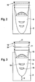
- a view from the front shows a second exemplary embodiment of a long hair cutter 10 attached to a shaver casing 2 with a top blade 11.
- This long hair cutter also can also be lifted out or in in relation to the shaver casing by means of a sliding switch 9.
- the same position numbers used in Figure 1 were used for the equivalent components in Figures 2 through 5 .
- the sliding switch 9 is connected to the long hair cutter 10 by a transmission mechanism ( Figures 4 and 5 - not shown).
- the long hair cutter 10 is connected to the blade casing 18 by means of a casing part 17; the blade casing 18 is integrated with the sliding switch 9.
- the blade casing 18 slides lengthwise over a first guide arrangement 19 into the shaver casing 2 (displacement direction V), whereas the long hair cutter 10 is moved up and down in the same direction over a second guide path 20, either solely into the blade casing 18 and/or partially also into the shaver casing 2.
- Figures 4 and 5 show a sketch-like partial sectional drawing of the transmission mechanism 21 according to the invention.
- Situated in the blade casing 18 are two guide paths 20 and 22 that stand perpendicular to each other, into each of which is fed a sliding element 24, 25.
- the lower sliding element 24 can, according to Figures 2 through 5 , be slid in a horizontal direction, i.e. in a direction perpendicular to the sliding switch 9, while the sliding element 25 running perpendicular to it can be slid parallel to the displacement direction V from bottom to top and back.
- ramps 26 and 27 wherein the right ramp 26 runs from the top left side to the bottom right side, thus constituting a decline, while the left ramp runs from the top right side to the bottom left side, thus constituting an incline.
- a possible extension of the ramps 26 and 27 forms an intersection point C whose included angle is preferably 90°.
- the ramp angles ⁇ , ⁇ and ⁇ are preferably 45°.
- other angles are conceivable, depending on the friction coefficients of the sliding elements 24 and 25.
- the ramp angles ⁇ , ⁇ and ⁇ are defined by the sides of the ramps 26, 27 and 28 and the movement and/or sliding directions R and S of the sliding elements 24 and 25.
- the sliding direction S runs parallel to the displacement direction V and the sliding direction R runs diagonal to it.
- the left ramp 27 is flush with the ramp 28, which is part of the sliding element 25.
- the sliding element 25 is connected to the long hair cutter 10 mechanically or in one piece.
- the sliding element 25 is connected by means of a lever arm 29 attached to it to a tension spring 30 that for its part is attached to the blade casing 18 on another end.
- Fig. 4 only sketches in this tension spring 30 and is only intended to suggest that the sliding element is always returned as soon as the sliding switch 9 also returns [to its original position]. In this case as well, many equivalent solutions for a return mechanism are possible but in the interest of simplicity they are not mentioned here.
- the sliding elements 24 and 25 are fed into the sliding surfaces 35 and 36, which face each other, so that they do not tilt in their guide paths 22 and 23.
- Suitable as materials for this purpose are especially good plastics that can slide into plastic paths easily, even without lubricants.
- the sliding surfaces 35 and 36 have several raised areas that together form the respective guide paths 22 and 23 for the sliding elements 24 and 25.
- the gaps 44 and 45 that lie in between save material, reduce the cost of production and, moreover, improve sliding properties.
- the mode of action of the shaving apparatus according to the invention is as follows:
- the sliding switch 9 If the sliding switch 9 is now brought to a third position, by sliding the sliding switch 9 the sliding element 24 is slid to the left in accordance with the sliding direction R into the guide path 22 until it has reached the position shown in Fig. 5 .
- the ramp 26 As the sliding switch 9 is slid, the ramp 26 at the same time slides alongside the fixed stop 31 and presses the sliding element to the left.
- the ramp 28 of the sliding element 25 slides up alongside the ramp 27 of the sliding element 24 and is pushed up in the sliding direction S into the guide path 20, as shown in Fig. 5 .
- This doubling of the distance traveled by the long hair cutter 10 allows it to move very rapidly and far away from the shaver casing 2 in the event the displacement path of the sliding switch 9 is small, making it easier and simpler to use.
- Only the long hair cutter 10 is now utilized because it stands far above the short hair cutter 41, which can no longer touch the surface of the skin. Greater ramp angles ⁇ , ⁇ and ⁇ would make greater displacement of the long hair cutter possible, but more effort would be required to slide the sliding switch 9.
Landscapes
- Life Sciences & Earth Sciences (AREA)
- Forests & Forestry (AREA)
- Engineering & Computer Science (AREA)
- Mechanical Engineering (AREA)
- Dry Shavers And Clippers (AREA)
Claims (6)
- Elektrisch betriebener Rasierapparat (1), aufweisend mindestens einen Kurzhaarschneider (41), der an einem Rasierergehäuse (2) angebracht ist, und einen Langhaarschneider oder Trimmer (10), der mittels eines Schiebeschalters (9) auf einer ersten Führungsbahn (19) ein- oder ausgefahren werden kann, wobei der Schneider oder Trimmer (10) unterhalb des Kurzhaarschneiders (41) am Rasierergehäuse (2) vormontiert und angebracht ist und aus einem Klingengehäuse (18) und einem in eine zweite Führungsbahn (20) am Klingengehäuse (18) eingeführten Gehäuseteil (17) besteht, zu dem hin eine obere und eine untere Klinge relativ zueinander durch einen elektrischen Antriebsmechanismus angetrieben werden können, wobei sich zwischen dem Rasierergehäuse (2) und dem Langhaarschneider (10) ein Übertragungsmechanismus (21) befindet, der den Verschiebeweg (b) des Langhaarschneiders (10) vergrößert, dadurch gekennzeichnet, dass der Übertragungsmechanismus (21) zum einen aus einem festen Anschlag (31), der am Rasierergehäuse (2) angebracht ist, und zum anderen aus einem Schiebeelement (24) besteht, das quer zur zweiten Führungsbahn (20) des Langhaarschneiders (10) in eine dritte Führungsbahn (22) geschoben werden kann, dass das Schiebeelement (24) in Verbindung mit dem Anschlag (31) mittels einer Rampe (26) funktioniert, die an dem Schiebelement (24) angebracht und in einem Winkel (α) gegenüber der Schieberichtung (R) geneigt ist, und dass das Schiebeelement (24) mittels einer Ablenkvorrichtung (25) mit dem Gehäuseteil (17) des Langhaarschneiders (10) verbunden ist.
- Rasierapparat nach Anspruch 1, dadurch gekennzeichnet, dass die Ablenkvorrichtung aus einem zweiten Schiebeelement (25) besteht, dass das zweite Schiebelelement (25) in den zweiten Führungsbahnen (20) läuft und dass sich das zweite Schiebeelement (25) über Gleitoberflächen (27, 28) in Gleitkontakt mit dem ersten Schiebelement (24) befindet.
- Rasierapparat nach Anspruch 2, dadurch gekennzeichnet, dass die beiden Gleitoberflächen (27, 28) parallel zueinander verlaufen und einen Winkel β von 45° gegenüber der Schieberichtung der Führungsbahn (22) bilden.
- Rasierapparat nach Anspruch 1, dadurch gekennzeichnet, dass die Ablenkvorrichtung (25) aus einem flexiblen Band besteht, das an dem ersten Schiebeelement (24) angebracht ist, wobei das Band zwangsweise in die Führungsbahnen (22, 20) eingeführt wird.
- Rasierapparat nach Anspruch 1, dadurch gekennzeichnet, dass die Ablenkvorrichtung (25) durch eine Rückstellfeder (30) beaufschlagt wird.
- Rasierapparat nach Anspruch 1, dadurch gekennzeichnet, dass die Führungsbahnen (20, 22) durch im Querschnitt längs verlaufende Löcher geformt werden, in die die Schiebeelemente (24, 25) präzise in Längsrichtung eingeschoben werden können.
Applications Claiming Priority (2)
| Application Number | Priority Date | Filing Date | Title |
|---|---|---|---|
| DE102009030202A DE102009030202A1 (de) | 2009-06-24 | 2009-06-24 | Elektrisch betriebener Rasierapparat |
| PCT/IB2010/052870 WO2010150214A1 (en) | 2009-06-24 | 2010-06-23 | Electrically operated shaving apparatus |
Publications (2)
| Publication Number | Publication Date |
|---|---|
| EP2445686A1 EP2445686A1 (de) | 2012-05-02 |
| EP2445686B1 true EP2445686B1 (de) | 2014-05-07 |
Family
ID=42727388
Family Applications (1)
| Application Number | Title | Priority Date | Filing Date |
|---|---|---|---|
| EP10731603.6A Active EP2445686B1 (de) | 2009-06-24 | 2010-06-23 | Elektrischer rasierapparat |
Country Status (3)
| Country | Link |
|---|---|
| EP (1) | EP2445686B1 (de) |
| DE (1) | DE102009030202A1 (de) |
| WO (1) | WO2010150214A1 (de) |
Family Cites Families (6)
| Publication number | Priority date | Publication date | Assignee | Title |
|---|---|---|---|---|
| NL7007687A (de) | 1970-05-28 | 1971-11-30 | ||
| US4085503A (en) * | 1974-12-23 | 1978-04-25 | Sunbeam Corporation | Electric dry shaver with adjustable long hair trimmer |
| AT368057B (de) * | 1980-04-03 | 1982-09-10 | Payer Lux Elektroprod | Elektrischer rasierapparat |
| DE3729257A1 (de) | 1987-09-02 | 1989-03-23 | Braun Ag | Trockenrasierapparat mit einem kurzhaarschneidsystem und einem verschiebbaren langhaarschneidsystem |
| DE4117988A1 (de) | 1991-06-03 | 1992-12-10 | Braun Ag | Elektrischer rasierapparat |
| DE4336231C1 (de) | 1993-10-23 | 1994-05-26 | Braun Ag | Trockenrasierapparat mit einem Kurzhaarschneidsystem und einem verschiebbaren Langhaarschneidsystem |
-
2009
- 2009-06-24 DE DE102009030202A patent/DE102009030202A1/de not_active Ceased
-
2010
- 2010-06-23 WO PCT/IB2010/052870 patent/WO2010150214A1/en not_active Ceased
- 2010-06-23 EP EP10731603.6A patent/EP2445686B1/de active Active
Also Published As
| Publication number | Publication date |
|---|---|
| DE102009030202A1 (de) | 2010-12-30 |
| EP2445686A1 (de) | 2012-05-02 |
| WO2010150214A1 (en) | 2010-12-29 |
Similar Documents
| Publication | Publication Date | Title |
|---|---|---|
| KR100900123B1 (ko) | 바리캉 | |
| CN1287523A (zh) | 包括一剪发装置和包括其角度位置可相对于剪发位置连续地调节的一梳子部分的剪发系统 | |
| US20090119928A1 (en) | Dual blade trimmer with slide-out blade assembly | |
| RU2018129104A (ru) | Механизм регулировки длины для машинки для стрижки волос | |
| WO2008032444A1 (en) | Sheet cutter | |
| JP2009119269A (ja) | 家具用ドライブ | |
| EP2445686B1 (de) | Elektrischer rasierapparat | |
| CN1170660C (zh) | 剃须刀 | |
| EP2365502B1 (de) | Elektrische Werkzeuge und Schaltgerät dafür | |
| JP4229203B2 (ja) | バリカン | |
| EP2158066B1 (de) | Elektrischer apparat und rasierapparat | |
| CN115462852A (zh) | 一种传动机构及电动腔镜吻合器 | |
| CN120187567A (zh) | 毛发切割器具及用于毛发切割器的切割单元 | |
| CN117158961B (zh) | 采血推发动力机构及使用其的采血器 | |
| CN103612271A (zh) | 切割式裁纸刀 | |
| CN203761919U (zh) | 可切换操作模式的园艺剪 | |
| CN210581455U (zh) | 一种易清洁的梳子 | |
| CN2676379Y (zh) | 开关机构 | |
| CN223045185U (zh) | 一种打印头组件及3d打印机 | |
| US20070130774A1 (en) | Electric shaving apparatus | |
| US12324569B2 (en) | Laryngoscope with blade position adjustment | |
| JP3646357B2 (ja) | オートカッタ装置 | |
| US7360311B2 (en) | Drive mechanism for power tool | |
| KR100576168B1 (ko) | 전기 바리깡 | |
| CN220860030U (zh) | 簸箕 |
Legal Events
| Date | Code | Title | Description |
|---|---|---|---|
| PUAI | Public reference made under article 153(3) epc to a published international application that has entered the european phase |
Free format text: ORIGINAL CODE: 0009012 |
|
| 17P | Request for examination filed |
Effective date: 20111129 |
|
| AK | Designated contracting states |
Kind code of ref document: A1 Designated state(s): AL AT BE BG CH CY CZ DE DK EE ES FI FR GB GR HR HU IE IS IT LI LT LU LV MC MK MT NL NO PL PT RO SE SI SK SM TR |
|
| DAX | Request for extension of the european patent (deleted) | ||
| GRAP | Despatch of communication of intention to grant a patent |
Free format text: ORIGINAL CODE: EPIDOSNIGR1 |
|
| INTG | Intention to grant announced |
Effective date: 20131016 |
|
| GRAS | Grant fee paid |
Free format text: ORIGINAL CODE: EPIDOSNIGR3 |
|
| GRAA | (expected) grant |
Free format text: ORIGINAL CODE: 0009210 |
|
| AK | Designated contracting states |
Kind code of ref document: B1 Designated state(s): AL AT BE BG CH CY CZ DE DK EE ES FI FR GB GR HR HU IE IS IT LI LT LU LV MC MK MT NL NO PL PT RO SE SI SK SM TR |
|
| REG | Reference to a national code |
Ref country code: GB Ref legal event code: FG4D |
|
| REG | Reference to a national code |
Ref country code: CH Ref legal event code: NV Representative=s name: BOHEST AG, CH Ref country code: AT Ref legal event code: REF Ref document number: 666239 Country of ref document: AT Kind code of ref document: T Effective date: 20140515 |
|
| REG | Reference to a national code |
Ref country code: IE Ref legal event code: FG4D |
|
| REG | Reference to a national code |
Ref country code: DE Ref legal event code: R096 Ref document number: 602010015868 Country of ref document: DE Effective date: 20140626 |
|
| REG | Reference to a national code |
Ref country code: NL Ref legal event code: T3 |
|
| REG | Reference to a national code |
Ref country code: LT Ref legal event code: MG4D |
|
| PG25 | Lapsed in a contracting state [announced via postgrant information from national office to epo] |
Ref country code: GR Free format text: LAPSE BECAUSE OF FAILURE TO SUBMIT A TRANSLATION OF THE DESCRIPTION OR TO PAY THE FEE WITHIN THE PRESCRIBED TIME-LIMIT Effective date: 20140808 Ref country code: IS Free format text: LAPSE BECAUSE OF FAILURE TO SUBMIT A TRANSLATION OF THE DESCRIPTION OR TO PAY THE FEE WITHIN THE PRESCRIBED TIME-LIMIT Effective date: 20140907 Ref country code: NO Free format text: LAPSE BECAUSE OF FAILURE TO SUBMIT A TRANSLATION OF THE DESCRIPTION OR TO PAY THE FEE WITHIN THE PRESCRIBED TIME-LIMIT Effective date: 20140807 Ref country code: FI Free format text: LAPSE BECAUSE OF FAILURE TO SUBMIT A TRANSLATION OF THE DESCRIPTION OR TO PAY THE FEE WITHIN THE PRESCRIBED TIME-LIMIT Effective date: 20140507 Ref country code: CY Free format text: LAPSE BECAUSE OF FAILURE TO SUBMIT A TRANSLATION OF THE DESCRIPTION OR TO PAY THE FEE WITHIN THE PRESCRIBED TIME-LIMIT Effective date: 20140507 Ref country code: LT Free format text: LAPSE BECAUSE OF FAILURE TO SUBMIT A TRANSLATION OF THE DESCRIPTION OR TO PAY THE FEE WITHIN THE PRESCRIBED TIME-LIMIT Effective date: 20140507 |
|
| PG25 | Lapsed in a contracting state [announced via postgrant information from national office to epo] |
Ref country code: PL Free format text: LAPSE BECAUSE OF FAILURE TO SUBMIT A TRANSLATION OF THE DESCRIPTION OR TO PAY THE FEE WITHIN THE PRESCRIBED TIME-LIMIT Effective date: 20140507 Ref country code: SE Free format text: LAPSE BECAUSE OF FAILURE TO SUBMIT A TRANSLATION OF THE DESCRIPTION OR TO PAY THE FEE WITHIN THE PRESCRIBED TIME-LIMIT Effective date: 20140507 Ref country code: ES Free format text: LAPSE BECAUSE OF FAILURE TO SUBMIT A TRANSLATION OF THE DESCRIPTION OR TO PAY THE FEE WITHIN THE PRESCRIBED TIME-LIMIT Effective date: 20140507 Ref country code: HR Free format text: LAPSE BECAUSE OF FAILURE TO SUBMIT A TRANSLATION OF THE DESCRIPTION OR TO PAY THE FEE WITHIN THE PRESCRIBED TIME-LIMIT Effective date: 20140507 Ref country code: LV Free format text: LAPSE BECAUSE OF FAILURE TO SUBMIT A TRANSLATION OF THE DESCRIPTION OR TO PAY THE FEE WITHIN THE PRESCRIBED TIME-LIMIT Effective date: 20140507 |
|
| PG25 | Lapsed in a contracting state [announced via postgrant information from national office to epo] |
Ref country code: PT Free format text: LAPSE BECAUSE OF FAILURE TO SUBMIT A TRANSLATION OF THE DESCRIPTION OR TO PAY THE FEE WITHIN THE PRESCRIBED TIME-LIMIT Effective date: 20140908 |
|
| PG25 | Lapsed in a contracting state [announced via postgrant information from national office to epo] |
Ref country code: BE Free format text: LAPSE BECAUSE OF FAILURE TO SUBMIT A TRANSLATION OF THE DESCRIPTION OR TO PAY THE FEE WITHIN THE PRESCRIBED TIME-LIMIT Effective date: 20140507 Ref country code: SK Free format text: LAPSE BECAUSE OF FAILURE TO SUBMIT A TRANSLATION OF THE DESCRIPTION OR TO PAY THE FEE WITHIN THE PRESCRIBED TIME-LIMIT Effective date: 20140507 Ref country code: RO Free format text: LAPSE BECAUSE OF FAILURE TO SUBMIT A TRANSLATION OF THE DESCRIPTION OR TO PAY THE FEE WITHIN THE PRESCRIBED TIME-LIMIT Effective date: 20140507 Ref country code: CZ Free format text: LAPSE BECAUSE OF FAILURE TO SUBMIT A TRANSLATION OF THE DESCRIPTION OR TO PAY THE FEE WITHIN THE PRESCRIBED TIME-LIMIT Effective date: 20140507 Ref country code: DK Free format text: LAPSE BECAUSE OF FAILURE TO SUBMIT A TRANSLATION OF THE DESCRIPTION OR TO PAY THE FEE WITHIN THE PRESCRIBED TIME-LIMIT Effective date: 20140507 Ref country code: EE Free format text: LAPSE BECAUSE OF FAILURE TO SUBMIT A TRANSLATION OF THE DESCRIPTION OR TO PAY THE FEE WITHIN THE PRESCRIBED TIME-LIMIT Effective date: 20140507 |
|
| REG | Reference to a national code |
Ref country code: DE Ref legal event code: R097 Ref document number: 602010015868 Country of ref document: DE |
|
| PLBE | No opposition filed within time limit |
Free format text: ORIGINAL CODE: 0009261 |
|
| STAA | Information on the status of an ep patent application or granted ep patent |
Free format text: STATUS: NO OPPOSITION FILED WITHIN TIME LIMIT |
|
| REG | Reference to a national code |
Ref country code: IE Ref legal event code: MM4A |
|
| 26N | No opposition filed |
Effective date: 20150210 |
|
| PG25 | Lapsed in a contracting state [announced via postgrant information from national office to epo] |
Ref country code: IE Free format text: LAPSE BECAUSE OF NON-PAYMENT OF DUE FEES Effective date: 20140623 Ref country code: IT Free format text: LAPSE BECAUSE OF FAILURE TO SUBMIT A TRANSLATION OF THE DESCRIPTION OR TO PAY THE FEE WITHIN THE PRESCRIBED TIME-LIMIT Effective date: 20140507 |
|
| REG | Reference to a national code |
Ref country code: DE Ref legal event code: R097 Ref document number: 602010015868 Country of ref document: DE Effective date: 20150210 |
|
| PG25 | Lapsed in a contracting state [announced via postgrant information from national office to epo] |
Ref country code: SI Free format text: LAPSE BECAUSE OF FAILURE TO SUBMIT A TRANSLATION OF THE DESCRIPTION OR TO PAY THE FEE WITHIN THE PRESCRIBED TIME-LIMIT Effective date: 20140507 |
|
| PG25 | Lapsed in a contracting state [announced via postgrant information from national office to epo] |
Ref country code: MT Free format text: LAPSE BECAUSE OF FAILURE TO SUBMIT A TRANSLATION OF THE DESCRIPTION OR TO PAY THE FEE WITHIN THE PRESCRIBED TIME-LIMIT Effective date: 20140507 |
|
| PG25 | Lapsed in a contracting state [announced via postgrant information from national office to epo] |
Ref country code: MC Free format text: LAPSE BECAUSE OF FAILURE TO SUBMIT A TRANSLATION OF THE DESCRIPTION OR TO PAY THE FEE WITHIN THE PRESCRIBED TIME-LIMIT Effective date: 20140507 Ref country code: SM Free format text: LAPSE BECAUSE OF FAILURE TO SUBMIT A TRANSLATION OF THE DESCRIPTION OR TO PAY THE FEE WITHIN THE PRESCRIBED TIME-LIMIT Effective date: 20140507 |
|
| REG | Reference to a national code |
Ref country code: FR Ref legal event code: PLFP Year of fee payment: 7 |
|
| PG25 | Lapsed in a contracting state [announced via postgrant information from national office to epo] |
Ref country code: BG Free format text: LAPSE BECAUSE OF FAILURE TO SUBMIT A TRANSLATION OF THE DESCRIPTION OR TO PAY THE FEE WITHIN THE PRESCRIBED TIME-LIMIT Effective date: 20140507 |
|
| PG25 | Lapsed in a contracting state [announced via postgrant information from national office to epo] |
Ref country code: LU Free format text: LAPSE BECAUSE OF NON-PAYMENT OF DUE FEES Effective date: 20140623 Ref country code: TR Free format text: LAPSE BECAUSE OF FAILURE TO SUBMIT A TRANSLATION OF THE DESCRIPTION OR TO PAY THE FEE WITHIN THE PRESCRIBED TIME-LIMIT Effective date: 20140507 Ref country code: HU Free format text: LAPSE BECAUSE OF FAILURE TO SUBMIT A TRANSLATION OF THE DESCRIPTION OR TO PAY THE FEE WITHIN THE PRESCRIBED TIME-LIMIT; INVALID AB INITIO Effective date: 20100623 |
|
| PGFP | Annual fee paid to national office [announced via postgrant information from national office to epo] |
Ref country code: CH Payment date: 20160525 Year of fee payment: 7 |
|
| PGFP | Annual fee paid to national office [announced via postgrant information from national office to epo] |
Ref country code: AT Payment date: 20160526 Year of fee payment: 7 |
|
| REG | Reference to a national code |
Ref country code: FR Ref legal event code: PLFP Year of fee payment: 8 |
|
| REG | Reference to a national code |
Ref country code: CH Ref legal event code: PL |
|
| REG | Reference to a national code |
Ref country code: AT Ref legal event code: MM01 Ref document number: 666239 Country of ref document: AT Kind code of ref document: T Effective date: 20170623 |
|
| PG25 | Lapsed in a contracting state [announced via postgrant information from national office to epo] |
Ref country code: LI Free format text: LAPSE BECAUSE OF NON-PAYMENT OF DUE FEES Effective date: 20170630 Ref country code: CH Free format text: LAPSE BECAUSE OF NON-PAYMENT OF DUE FEES Effective date: 20170630 |
|
| REG | Reference to a national code |
Ref country code: FR Ref legal event code: PLFP Year of fee payment: 9 |
|
| PG25 | Lapsed in a contracting state [announced via postgrant information from national office to epo] |
Ref country code: AT Free format text: LAPSE BECAUSE OF NON-PAYMENT OF DUE FEES Effective date: 20170623 |
|
| PG25 | Lapsed in a contracting state [announced via postgrant information from national office to epo] |
Ref country code: MK Free format text: LAPSE BECAUSE OF FAILURE TO SUBMIT A TRANSLATION OF THE DESCRIPTION OR TO PAY THE FEE WITHIN THE PRESCRIBED TIME-LIMIT Effective date: 20140507 |
|
| PG25 | Lapsed in a contracting state [announced via postgrant information from national office to epo] |
Ref country code: AL Free format text: LAPSE BECAUSE OF FAILURE TO SUBMIT A TRANSLATION OF THE DESCRIPTION OR TO PAY THE FEE WITHIN THE PRESCRIBED TIME-LIMIT Effective date: 20140507 |
|
| P01 | Opt-out of the competence of the unified patent court (upc) registered |
Effective date: 20230430 |
|
| PGFP | Annual fee paid to national office [announced via postgrant information from national office to epo] |
Ref country code: NL Payment date: 20250516 Year of fee payment: 16 |
|
| PGFP | Annual fee paid to national office [announced via postgrant information from national office to epo] |
Ref country code: DE Payment date: 20250429 Year of fee payment: 16 |
|
| PGFP | Annual fee paid to national office [announced via postgrant information from national office to epo] |
Ref country code: GB Payment date: 20250501 Year of fee payment: 16 |
|
| PGFP | Annual fee paid to national office [announced via postgrant information from national office to epo] |
Ref country code: FR Payment date: 20250508 Year of fee payment: 16 |