EP2445461B1 - Vorrichtung für die ophthalmologische laserchirurgie - Google Patents
Vorrichtung für die ophthalmologische laserchirurgie Download PDFInfo
- Publication number
- EP2445461B1 EP2445461B1 EP09768502.8A EP09768502A EP2445461B1 EP 2445461 B1 EP2445461 B1 EP 2445461B1 EP 09768502 A EP09768502 A EP 09768502A EP 2445461 B1 EP2445461 B1 EP 2445461B1
- Authority
- EP
- European Patent Office
- Prior art keywords
- temperature
- contact surface
- focal point
- laser beam
- eye
- Prior art date
- Legal status (The legal status is an assumption and is not a legal conclusion. Google has not performed a legal analysis and makes no representation as to the accuracy of the status listed.)
- Active
Links
- 238000002430 laser surgery Methods 0.000 title claims description 9
- 230000003287 optical effect Effects 0.000 claims description 40
- 238000011282 treatment Methods 0.000 claims description 36
- 230000005855 radiation Effects 0.000 claims description 31
- 238000000034 method Methods 0.000 claims description 14
- 238000003384 imaging method Methods 0.000 claims description 11
- 230000006870 function Effects 0.000 claims description 6
- 238000007493 shaping process Methods 0.000 claims description 4
- 238000012634 optical imaging Methods 0.000 claims 2
- 238000004519 manufacturing process Methods 0.000 description 15
- 238000005259 measurement Methods 0.000 description 14
- 239000007943 implant Substances 0.000 description 9
- 210000004087 cornea Anatomy 0.000 description 5
- 238000005520 cutting process Methods 0.000 description 5
- 230000004044 response Effects 0.000 description 5
- 238000006073 displacement reaction Methods 0.000 description 4
- 230000000694 effects Effects 0.000 description 4
- 239000007788 liquid Substances 0.000 description 4
- 238000011156 evaluation Methods 0.000 description 3
- 239000011521 glass Substances 0.000 description 3
- 238000013532 laser treatment Methods 0.000 description 3
- 239000000463 material Substances 0.000 description 3
- 238000002281 optical coherence-domain reflectometry Methods 0.000 description 3
- 230000008878 coupling Effects 0.000 description 2
- 238000010168 coupling process Methods 0.000 description 2
- 238000005859 coupling reaction Methods 0.000 description 2
- 230000008901 benefit Effects 0.000 description 1
- 230000005540 biological transmission Effects 0.000 description 1
- 230000015572 biosynthetic process Effects 0.000 description 1
- 238000009529 body temperature measurement Methods 0.000 description 1
- 230000008859 change Effects 0.000 description 1
- 238000006243 chemical reaction Methods 0.000 description 1
- 239000002826 coolant Substances 0.000 description 1
- 238000004132 cross linking Methods 0.000 description 1
- 230000007547 defect Effects 0.000 description 1
- 230000001419 dependent effect Effects 0.000 description 1
- 238000011161 development Methods 0.000 description 1
- 230000018109 developmental process Effects 0.000 description 1
- 238000000605 extraction Methods 0.000 description 1
- 238000005755 formation reaction Methods 0.000 description 1
- 230000003993 interaction Effects 0.000 description 1
- 230000004410 intraocular pressure Effects 0.000 description 1
- 238000002360 preparation method Methods 0.000 description 1
- 238000012545 processing Methods 0.000 description 1
- 230000009467 reduction Effects 0.000 description 1
- 238000005070 sampling Methods 0.000 description 1
- 238000001228 spectrum Methods 0.000 description 1
- 238000002560 therapeutic procedure Methods 0.000 description 1
- 238000011144 upstream manufacturing Methods 0.000 description 1
- 238000001429 visible spectrum Methods 0.000 description 1
- 238000003466 welding Methods 0.000 description 1
Images

Classifications
-
- A—HUMAN NECESSITIES
- A61—MEDICAL OR VETERINARY SCIENCE; HYGIENE
- A61F—FILTERS IMPLANTABLE INTO BLOOD VESSELS; PROSTHESES; DEVICES PROVIDING PATENCY TO, OR PREVENTING COLLAPSING OF, TUBULAR STRUCTURES OF THE BODY, e.g. STENTS; ORTHOPAEDIC, NURSING OR CONTRACEPTIVE DEVICES; FOMENTATION; TREATMENT OR PROTECTION OF EYES OR EARS; BANDAGES, DRESSINGS OR ABSORBENT PADS; FIRST-AID KITS
- A61F9/00—Methods or devices for treatment of the eyes; Devices for putting in contact-lenses; Devices to correct squinting; Apparatus to guide the blind; Protective devices for the eyes, carried on the body or in the hand
- A61F9/007—Methods or devices for eye surgery
- A61F9/008—Methods or devices for eye surgery using laser
- A61F9/00825—Methods or devices for eye surgery using laser for photodisruption
- A61F9/00831—Transplantation
-
- A—HUMAN NECESSITIES
- A61—MEDICAL OR VETERINARY SCIENCE; HYGIENE
- A61F—FILTERS IMPLANTABLE INTO BLOOD VESSELS; PROSTHESES; DEVICES PROVIDING PATENCY TO, OR PREVENTING COLLAPSING OF, TUBULAR STRUCTURES OF THE BODY, e.g. STENTS; ORTHOPAEDIC, NURSING OR CONTRACEPTIVE DEVICES; FOMENTATION; TREATMENT OR PROTECTION OF EYES OR EARS; BANDAGES, DRESSINGS OR ABSORBENT PADS; FIRST-AID KITS
- A61F9/00—Methods or devices for treatment of the eyes; Devices for putting in contact-lenses; Devices to correct squinting; Apparatus to guide the blind; Protective devices for the eyes, carried on the body or in the hand
- A61F9/007—Methods or devices for eye surgery
- A61F9/008—Methods or devices for eye surgery using laser
- A61F9/00825—Methods or devices for eye surgery using laser for photodisruption
- A61F9/00836—Flap cutting
-
- A—HUMAN NECESSITIES
- A61—MEDICAL OR VETERINARY SCIENCE; HYGIENE
- A61B—DIAGNOSIS; SURGERY; IDENTIFICATION
- A61B17/00—Surgical instruments, devices or methods
- A61B2017/00017—Electrical control of surgical instruments
- A61B2017/00022—Sensing or detecting at the treatment site
- A61B2017/00084—Temperature
-
- A—HUMAN NECESSITIES
- A61—MEDICAL OR VETERINARY SCIENCE; HYGIENE
- A61F—FILTERS IMPLANTABLE INTO BLOOD VESSELS; PROSTHESES; DEVICES PROVIDING PATENCY TO, OR PREVENTING COLLAPSING OF, TUBULAR STRUCTURES OF THE BODY, e.g. STENTS; ORTHOPAEDIC, NURSING OR CONTRACEPTIVE DEVICES; FOMENTATION; TREATMENT OR PROTECTION OF EYES OR EARS; BANDAGES, DRESSINGS OR ABSORBENT PADS; FIRST-AID KITS
- A61F9/00—Methods or devices for treatment of the eyes; Devices for putting in contact-lenses; Devices to correct squinting; Apparatus to guide the blind; Protective devices for the eyes, carried on the body or in the hand
- A61F9/007—Methods or devices for eye surgery
- A61F9/008—Methods or devices for eye surgery using laser
- A61F2009/00844—Feedback systems
-
- A—HUMAN NECESSITIES
- A61—MEDICAL OR VETERINARY SCIENCE; HYGIENE
- A61F—FILTERS IMPLANTABLE INTO BLOOD VESSELS; PROSTHESES; DEVICES PROVIDING PATENCY TO, OR PREVENTING COLLAPSING OF, TUBULAR STRUCTURES OF THE BODY, e.g. STENTS; ORTHOPAEDIC, NURSING OR CONTRACEPTIVE DEVICES; FOMENTATION; TREATMENT OR PROTECTION OF EYES OR EARS; BANDAGES, DRESSINGS OR ABSORBENT PADS; FIRST-AID KITS
- A61F9/00—Methods or devices for treatment of the eyes; Devices for putting in contact-lenses; Devices to correct squinting; Apparatus to guide the blind; Protective devices for the eyes, carried on the body or in the hand
- A61F9/007—Methods or devices for eye surgery
- A61F9/008—Methods or devices for eye surgery using laser
- A61F2009/00861—Methods or devices for eye surgery using laser adapted for treatment at a particular location
- A61F2009/00872—Cornea
-
- A—HUMAN NECESSITIES
- A61—MEDICAL OR VETERINARY SCIENCE; HYGIENE
- A61F—FILTERS IMPLANTABLE INTO BLOOD VESSELS; PROSTHESES; DEVICES PROVIDING PATENCY TO, OR PREVENTING COLLAPSING OF, TUBULAR STRUCTURES OF THE BODY, e.g. STENTS; ORTHOPAEDIC, NURSING OR CONTRACEPTIVE DEVICES; FOMENTATION; TREATMENT OR PROTECTION OF EYES OR EARS; BANDAGES, DRESSINGS OR ABSORBENT PADS; FIRST-AID KITS
- A61F9/00—Methods or devices for treatment of the eyes; Devices for putting in contact-lenses; Devices to correct squinting; Apparatus to guide the blind; Protective devices for the eyes, carried on the body or in the hand
- A61F9/007—Methods or devices for eye surgery
- A61F9/008—Methods or devices for eye surgery using laser
- A61F2009/00897—Scanning mechanisms or algorithms
-
- A—HUMAN NECESSITIES
- A61—MEDICAL OR VETERINARY SCIENCE; HYGIENE
- A61F—FILTERS IMPLANTABLE INTO BLOOD VESSELS; PROSTHESES; DEVICES PROVIDING PATENCY TO, OR PREVENTING COLLAPSING OF, TUBULAR STRUCTURES OF THE BODY, e.g. STENTS; ORTHOPAEDIC, NURSING OR CONTRACEPTIVE DEVICES; FOMENTATION; TREATMENT OR PROTECTION OF EYES OR EARS; BANDAGES, DRESSINGS OR ABSORBENT PADS; FIRST-AID KITS
- A61F9/00—Methods or devices for treatment of the eyes; Devices for putting in contact-lenses; Devices to correct squinting; Apparatus to guide the blind; Protective devices for the eyes, carried on the body or in the hand
- A61F9/007—Methods or devices for eye surgery
- A61F9/008—Methods or devices for eye surgery using laser
- A61F9/009—Auxiliary devices making contact with the eyeball and coupling in laser light, e.g. goniolenses
Definitions
- the invention relates to a device for ophthalmic laser surgery and an associated method.
- Pulsed laser radiation is used in numerous techniques of treating the human eye.
- the local control of the beam focus of the laser beam in the z-direction (meaning the propagation direction of the laser beam according to the usual notation) always takes place with reference to a known reference point or a known reference surface in the coordinate system of the laser device.
- different reference points or reference surfaces can serve as a reference for the z-control of the beam focus.
- the eye to be treated is pressed against a transparent contact element which, with its eye-facing contact surface, forms a reference surface for the positioning of the beam focus in the z-direction.
- treatment techniques which serve to produce incisions in the eye tissue by means of focused femtosecond laser radiation frequently make use of such contact elements as the z-reference for the laser focus.
- the cut or the individual photodisruption (the production of cuts in the human eye by means of pulsed femtosecond laser radiation is based regularly on the effect of the so-called laser-induced optical breakthrough to a Photodisruption leads) is located at the desired position in the depth of the eye tissue.
- Lasertechnisch generated cuts occur for example in the so-called Fs-LASIK, in which a designated in the art as Flap anterior cover disc of the cornea is cut free by femtosecond laser radiation to subsequently as in the classical LASIK technique (LASIK: Laser In Sito Keratomileusis) to fold the flap still hanging in a hinge area ( hinge ) on the remaining corneal tissue and ablating the tissue thus exposed by means of UV laser radiation.
- LASIK Laser In Sito Keratomileusis
- Another application for attachment intrageneal sections in the eye tissue is the so-called corneal lenrequestingextraction, in which within the corneal tissue a lense-shaped slice is completely cut out by means of femtosecond laser radiation.
- This slice is then removed through an additional cut led out to the ocular surface (the additional incision is made either by means of a scalpel or likewise by means of femtosecond laser radiation).
- Corneal grafting (keratoplasty) or other incisions, for example for corneal ring segments, can also produce corneal incision by means of focused pulsed laser radiation.
- the contact element (applicator) carrying the contact surface is often a disposable article which must be exchanged before each treatment.
- Certain manufacturing tolerances can not be ruled out regularly in the manufacture of the contact elements, even with the greatest precision of manufacture. Therefore, after an exchange of the contact element, the z-position of the eye-facing contact surface - albeit only slightly - be different than in the previously used contact element.
- the smallest possible focal diameter is sought in order to limit the photodisruptive effect locally as closely as possible.
- Modern devices for example, work with focus diameters in the low single-digit ⁇ m range.
- the depth of cut in the target tissue is often defined with extremely high accuracy (incision depth tolerances ⁇ 5 ⁇ m).
- the tissue to be treated and the optical system of the laser are usually fixedly coupled to one another by a contact element in order to achieve the required depth of cut with corresponding precision in the z-direction.
- This requires a correspondingly high manufacturing accuracy of the contact element, which, however, can not always be guaranteed.
- the problem arises of a non-precise z-directional cut in the corneal tissue i. the manufacturing tolerances for these contact elements go directly into the inaccuracies for the depth of cut in the tissue.
- Applicators are generally made in the state of the art with the appropriate effort.
- the optical system of the laser is adjusted to the required distance between the optical system and the cutting plane by means of a reference applicator utilizing the interaction between laser radiation and material. This is for example already from the WO 2004/032810 known.
- the distance between the tissue and the laser system, and thus directly the real depth of cut in the tissue, is significantly affected by the dimension of the applicator, i. the real optical length of the applicator in the z-direction, determined. This makes it necessary to achieve the required precision of the depth of cut that the applicators must be made with correspondingly small tolerances in terms of their dimension (the relative length accuracy is significantly ⁇ 1 ⁇ ), which significantly increases the manufacturing cost of these applicators and especially in large quantities of disposable items directly on the treatment costs and thus on the so-called "Costs of Ownership" effect.
- a position measurement of the contact surface based on the propagation direction of the treatment laser beam is performed by means of a measuring device and adjusted by means of an electronic evaluation and control arrangement connected to the focus of the treatment laser beam depending on the position measurement data obtained by the measuring device.
- the pamphlets US 2008/0039769 A1 and US 2007/0135805 A1 disclose an implant blank suitable for use in altering the curvature of the cornea of a patient, comprising: a first surface adapted to be placed directly on the surface of the living cornea of the patient; a second.
- the implant blank comprises a material whose properties enable light having a wavelength within the visible spectrum to pass therethrough and prevent substantially all of the light having a wavelength within the laser light spectrum from passing therethrough
- the implant blank further comprises a wall surface extending between the first surface and the second surface and defining an opening in the implant blank, and in that this implant blank comprises one of the following: (i) a region that extends extends from the opening to an edge region of the implant blank and has a thickness which is greater than the thickness of an adjacent section of the implant blank or (ii) a region which extends from the opening to an edge region of the implant blank and has a thickness less than the thickness of an adjacent portion of the implant at-Rohlings is.
- the publication WO2011 / 015205 discloses a device for laser ophthalmology comprising a source of pulsed femtosecond laser radiation, components for guiding and focusing the laser radiation on or in a tissue of an eye to be treated, a control unit controlling the source which is set up to control the source between at least two operating modes, each with different radiation properties of the laser radiation, wherein in a first operating mode, the radiation properties of the laser radiation are tuned to the attachment of an incision in the tissue and in a second mode of operation, the radiation properties of the laser radiation to a Tissue welding or cross-linking are tuned.
- the effective depth of cut in addition to the stated manufacturing tolerances, depends on temperature drifts in the dimension of the applicator as well as the effective focal length of the entire optic, i. the real optical length of the applicator in the propagation direction of the treatment laser beam and the focal length of the optics of a laser system vary depending on the temperature application range. In the conventional temperature range of medical devices of 15 ° C - 35 ° C, these drifts can easily add up to 30 ⁇ m to 50 ⁇ m. Thus, the desired cutting depth tolerances are ⁇ 5 microns difficult or no longer achievable.
- a device for ophthalmic laser surgery comprising: an imaging optical system for imaging a treatment laser beam at a focal point, a temperature measuring device for measuring a temperature associated with the imaging system, and an electronic control device connected to the temperature measuring device and adapted to operate Control focus adjustment depending on the measured temperature.
- the device preferably comprises a contact surface for the shaping contact of an eye to be treated and a radiation source for providing the treatment laser beam.
- the imaging system may preferably include optical components for directing the treatment laser beam through the contact surface to the eye.
- the presetting of the focus point can be done in different ways.
- the position of the focus in the z-direction may preferably be preset by knowing the z-position of the contact surface with respect to a given reference point in a fixed coordinate system of the laser-surgical device.
- a patient adapter (applicator) is used, whose real optical length in the propagation direction of the treatment laser beam (z-direction) has been made highly accurate, so that the focal point can be preset to the known length.
- Changes in the length of the applicator or changes in the effective focal length of the optical components contained in the device due to the temperature changing around the device can be detected by the temperature measuring device and taken into account accordingly by the control arrangement.
- the effective optical distance (the real optical length) between the eye-facing surface of the applicator (the contact surface) and the surface facing away from the eye (the surface facing the optical components of the device) has already been measured outside the device and, for example, via a coding imprinted on the associated applicator.
- This coding can then preferably be read out by the device, eg automatically or manually, and passed on to the control device become. Based on the read value, the control arrangement may initially preset the focus point.
- the device preferably has a measuring device for position measurement of the contact surface with respect to the propagation direction of the treatment laser beam.
- the measuring device preferably comprises a second radiation source providing a measuring beam.
- the optical components are then preferably designed and arranged to also direct the measuring beam through the contact surface to the eye.
- the measuring device may preferably provide position measuring data by means of the measuring beam, which are representative of the measured position of the contact surface at at least one point thereof, and may pass on the determined position measuring data to the control arrangement.
- the electronic control device in response, sets the focus point depending on the positional measurement data.
- the focus point in the z-direction can be preferably preset first, so that manufacturing defects are reduced or avoided. Based on the measured temperature, the preset focus point can then be adjusted or readjusted.
- the adjustment or readjustment of the preset focal point can preferably take place at predetermined time intervals, for example, by a repeated measurement of the temperature by the temperature measuring device after predetermined periods of time.
- a readjustment may preferably take place when the measured temperature exceeds the previously measured temperature by a predetermined limit. In such a case, a significant temperature drift would be expected, which requires a readjustment of the focal point.
- a reduction of the predetermined limit value allows a more accurate but more complex readjustment of the focal point.
- the predetermined time intervals and the predetermined limit value are stored in a memory connected to the control arrangement, so that the control arrangement can read these values if necessary and control the temperature measuring device and the readjustment of the focus point accordingly.
- a renewed temperature measurement takes place only if, for example by a user, a corresponding instruction is input to the temperature measuring device or related components.
- the temperature measuring device may preferably comprise one or more temperature sensors, which are arranged on one or more of the optical components and connected to the electronic control device.
- the optical components preferably form on the one hand a scanning unit for deflecting the treatment laser beam in a plane orthogonal to its beam path (x-y plane) or a 3D scanning unit for three-dimensional deflection of the treatment laser beam and on the other hand focusing optics for focusing the treatment laser beam into the laser beam focus.
- preferably two temperature sensors are respectively arranged on the scanning unit and on the focusing optics.
- one or more than two temperature sensors can also be arranged on the scanning unit and on the focusing optics.
- the optical components preferably comprise at least one controllable optical element.
- the controllable optical element is formed by a position-variable in the propagation direction of the treatment laser beam lens.
- the control arrangement may preferably generate a manipulated variable for readjustment of the preset focal point as a function of the measured temperature.
- the lens is preferably movable or repositionable mechanically along the optical beam path.
- the control arrangement is preferably configured to change the position of the positionally variable lens by the determined steepness to adapt the focus point.
- a controllable liquid lens of variable refractive power With unchanged z-position and otherwise unchanged setting of the focusing lens, a z-displacement of the beam focus can be achieved by moving a longitudinally adjustable lens or by refractive power variation of a liquid lens, thereby adjusting the focus point to the changed temperature. It is understood that other components are preferred for z-adjustment of the beam focus, such as a deformable mirror.
- the control arrangement may preferably further comprise or be connected to a memory unit in which the dependency of the focal point on the temperature is stored as a function.
- the temperature dependencies of all materials used in the device and all distances occurring in the device may preferably be
- the temperature response is preferably determined separately for the scanning unit and the focusing optics and recorded, but can also be calculated together for them.
- the determined temperature response may preferably be stored as a set of curves in the memory unit and queried as required by the control arrangement and used to adjust the focus point based on the stored set of curves.
- the control arrangement can furthermore preferably be set up to generate different manipulated variables for the controllable optical element during the readjustment of the focal point in the z-direction at several different locations in an x-y plane orthogonal to the z-direction. This makes it possible, for example, individually compensate for different effects of temperature changes on the position of the contact surface in the x-y plane.
- the measuring device is preferably a coherence-optical interferometric measuring device and has an optical interferometer for this purpose.
- the contact surface will preferably be part of an exchangeably arranged disposable component, for example a disposable applicator. However, it should be emphasized that no disposable character of the element carrying the contact surface is required.
- the device can be used in embodiments with fixed built-in or at least reusable contact surface.
- the contact surface is preferably formed by a transparent applanation plate or a transparent contact glass.
- Applanation plates have at least on their facing plate side a flat applanation surface with which a leveling of the front of the eye is achieved.
- the use of Applanationsplatten for referencing the eye to be treated is regularly low under the Viewpoint of a high beam quality of the laser radiation.
- the advantage of such contact glasses is z. B. a lesser increase in intraocular pressure when pressed against the eye.
- the contact surface is preferably formed by a transparent contact element, which is part of a patient adapter, in particular interchangeably coupled with a focusing lens of the device.
- the method further includes the steps of establishing a forming abutment contact between an eye and a contact surface and directing the treatment laser beam through the contact surface to the eye.
- position measurement data representative of a measured position of the contact surface at at least one location thereof relative to the propagation direction of the treatment laser beam are determined or read as described above. Regardless of whether the position measurement data has been acquired or read, the focus point is preset depending on the position measurement data and can be subsequently readjusted based on the measured temperature.
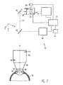
- the laser surgical device according to both embodiments is indicated generally at 10.
- the laser surgical device 10 has a femtosecond laser (Fs laser) 12, which emits pulsed laser radiation with pulse durations in the range of femtoseconds.
- the laser radiation propagates along an optical beam path 14 and finally reaches an eye 16 to be treated.
- Various components for guiding and shaping the laser radiation are arranged in the beam path 14.
- these components comprise a focusing objective 18 (for example an F-theta objective) and a scanner 20 arranged upstream of the objective 18, by means of which the laser radiation provided by the laser 12 can be deflected in a plane orthogonal to the beam path 14 (x-y plane).
- a drawn coordinate system illustrates this plane as well as a z-axis defined by the direction of the beam path 14.
- the scanner 20 is constructed, for example, in a manner known per se from a pair of galvanometrically controlled deflection mirrors which are each responsible for the beam deflection in the direction of one of the axes spanning the x-y plane.
- a central control unit 22 controls the scanner 20 in accordance with a control program stored in a memory 24 which implements a cutting profile to be generated in the eye 16 (represented by a three-dimensional pattern of sampling points at which photodisruption is to be effected).
- the mentioned components for guiding and shaping the laser radiation include at least one controllable optical element for z-adjustment of the beam focus of the laser radiation.
- this optical element is formed by a lens.
- a suitable actuator 28 which in turn is controlled by the control unit 22.
- the lens 26 can be moved mechanically along the optical beam path 14.
- a controllable liquid lens of variable refractive power With unchanged z-position and otherwise unchanged setting of the focusing lens 18 can be achieved by moving a longitudinally adjustable lens or by refractive power variation of a liquid lens, a z-displacement of the beam focus.
- the lens 26 can also be part of the scanner 20 and the scanner 20 formed thereby can be arranged both before and after the semitransparent deflection mirror 40. The case where the lens is part of the scanner 20 and this scanner 20 including the lens 26 is disposed in front of the reflecting mirror 42 will be described later with reference to FIG FIG. 2 explained.
- the focusing objective 18 is coupled to a patient adapter 30, which serves to establish a mechanical coupling between the eye 16 and the focusing objective 18.
- a patient adapter 30 which serves to establish a mechanical coupling between the eye 16 and the focusing objective 18.
- suction ring is placed on the eye and fixed there by suction.
- the suction ring and the patient adapter 30 form a defined mechanical interface, which allows a coupling of the patient adapter 30 to the suction ring.
- the international patent application PCT / EP2008 / 006962 be referenced, the entire contents of which are hereby incorporated by reference.
- the patient adapter 30 serves as a carrier for a transparent contact element, which in the example shown is designed as a plane-parallel applanation plate.
- the patient adapter 30 comprises, for example, a cone sleeve body, on whose narrower (in the drawing lower) sleeve end the applanation plate 32 is arranged.
- the wider (in the drawing upper) sleeve end of the patient adapter 30 is attached to the focusing lens 18 and there has suitable formations that allow an optionally releasable fixation of the patient adapter 30 to the focusing lens 18.
- the applanation plate 32 is a hygienically critical article Therefore, it is expedient to replace it after each treatment.
- the applanation plate 32 can be exchangeably attached to the patient adapter 30.
- the patient adapter 30 together with the applanation plate 32 form a disposable unit, to which the applanation plate 32 can be permanently connected to the patient adapter 30.
- the eye-facing underside of the applanation plate 32 forms a flat contact surface 34 against which the eye 16 is pressed in preparation for the treatment. This causes a planarization of the anterior surface of the eye with simultaneous deformation of the cornea of the eye 16, designated 36.
- the contact surface 34 In order to be able to use the contact surface 34 as a reference for the presetting of the beam focus in the z-direction, it is necessary to know its z-position in the coordinate system of the laser-surgical device. Due to unavoidable manufacturing tolerances can not be ruled out that when installing different applanation plates or different patient adapter 30, which are each equipped with a applanation plate 32, the z-position and possibly also the angular position of the contact surface 34 shows more or less significant fluctuations. Insofar as these variations in the z-default of the beam focus are disregarded, unwanted errors in the actual position of the incisions produced in the eye 16 result.
- the laser surgical device 10 includes a coherence-optical interferometric measuring device 38, for example, an OLCR measuring device (OLCR: Optical Low Coherence Reflectrometry), which emits a measuring beam which is coupled by means of immovably arranged, semitransparent deflecting mirror 40 in the beam path 14, in which also the treatment laser radiation of the laser 12 is running.
- the measuring device 38 brings the generated measuring beam into interference with a reflection beam returning from the eye 16. From the interference measurement data obtained in this regard, the z-position of the contact surface 34 within the coordinate system of the laser-surgical device can be determined. Therefore, the interference measurement data can also be referred to as position measurement data.
- the control unit 22 receives the interference measurement data from the measuring device 38 and calculates therefrom the z-position of that point of the contact surface 34 at which the measuring beam impinged or through which the measuring beam passed.
- the measuring beam emitted by the measuring device 38 passes through the scanner 20. This makes it possible to use the deflection function of the scanner 20 also for the measuring beam.
- the scanner module 20 could also include a second separate scanner for the OLCR alone, which works much faster with smaller mirrors.
- control unit 22 takes into account the thus determined actual z-position of the contact surface 34 in the z-control of the beam focus, such that the incision is actually generated at the intended position in the depth of the cornea 36.
- the evaluation and control unit 22 references the z-position of the beam focus to be set to the measured z-position of the contact surface 34.
- the laser surgical device 10 has four temperature sensors 50, 52, 54, 56, two of which are arranged on the scanner 20 and two on the focusing lens 18.
- the temperature sensors measure the real temperature at their respective positions and relay the measured temperature values to the control unit 22.
- the transmission of the temperature values to the control unit 22 may be wireless or wired, ie the temperature sensors 50, 52, 54, 56 may be wirelessly or wired to the control unit 22 in connection.
- the scanner 20 and thus the temperature sensors 50, 52 arranged on the scanner 20 are wired to the control unit 22 while the temperature sensors 54, 56 arranged on the focusing lens 18 are wirelessly connected to the control unit 22 in order to supply their temperature readings to the control unit 22 Pass control unit 22 for further processing.
- a temperature response of the effective focal length is deposited as a set of curves both for the scanner 20 and for the focusing lens 18.
- the control unit evaluates the corresponding function in the presence of a new temperature measured value and generates a corresponding manipulated variable for readjustment of the preset z-position of the lens 26. If one or both of the temperature sensors 50, 52 mounted on the scanner 20 determines a temperature value (during the measurement of two temperature values by the two temperature sensors 50, 52, an average temperature value formed from the two values is used), the temperature sensor transmits the measured temperature value to the control unit 22.
- the latter searches the memory 20 for the associated temperature response for the scanner 20, generates a manipulated variable therefrom and transmits it to the actuator 28, which shifts the lens 26 in the z direction in accordance with the manipulated variable.
- the preset position of the beam focus is readjusted in such a way that changes in the real optical length of the patient adapter and / or the effective focal length of the laser surgical device 10 that occur due to fluctuations in the real temperature are taken into account and compensated for.
- the scanner 20 includes the positionally displaceable in the propagation direction of the treatment laser beam lens 26 and is arranged in the propagation direction of the laser radiation in front of the deflection mirror 42.
- the scanner 20 is a 3D scanner having three-dimensional scanning properties, so that the laser radiation can be deflected in any direction (x, y, z) from the 3D scanner 20.
- the recording and evaluation of the temperature measured values by means of the temperature sensors 50, 52, 54, 56 and the control unit 22 is analogous to the in FIG. 1 shown first embodiment. In contrast to the first embodiment takes place in the in FIG. 2 Both the focus point preset and the focus point readjustment by the 3D scanner 20, which is controlled by the control unit 22, are shown in the second embodiment shown.
Landscapes
- Health & Medical Sciences (AREA)
- Ophthalmology & Optometry (AREA)
- Heart & Thoracic Surgery (AREA)
- Vascular Medicine (AREA)
- Veterinary Medicine (AREA)
- Surgery (AREA)
- Engineering & Computer Science (AREA)
- Biomedical Technology (AREA)
- Public Health (AREA)
- Nuclear Medicine, Radiotherapy & Molecular Imaging (AREA)
- Life Sciences & Earth Sciences (AREA)
- Animal Behavior & Ethology (AREA)
- General Health & Medical Sciences (AREA)
- Physics & Mathematics (AREA)
- Optics & Photonics (AREA)
- Transplantation (AREA)
- Laser Surgery Devices (AREA)
- Laser Beam Processing (AREA)
Description
- Die Erfindung betrifft eine Vorrichtung für die ophthalmologische Laserchirurgie sowie ein zugehöriges Verfahren.
- Gepulste Laserstrahlung kommt bei zahlreichen Techniken der Behandlung des menschlichen Auges zum Einsatz. Die örtliche Steuerung des Strahlfokus des Laserstrahls in z-Richtung (gemeint ist hiermit gemäß üblicher Notation die Ausbreitungsrichtung des Laserstrahls) erfolgt stets mit Bezug auf einen bekannten Referenzpunkt oder eine bekannte Referenzfläche im Koordinatensystem der Laservorrichtung.
- Je nach Behandlungsart können unterschiedliche Referenzpunkte oder Referenzflächen als Bezug für die z-Steuerung des Strahlfokus dienen. Bei einigen dieser Techniken wird das zu behandelnde Auge gegen ein transparentes Kontaktelement gedrückt, das mit seiner augenzugewandten Kontaktfläche eine Referenzfläche für die Positionierung des Strahlfokus in z-Richtung bildet. Insbesondere Behandlungstechniken, die der Erzeugung von Schnitten (Inzisionen) im Augengewebe mittels fokussierter Femtosekunden-Laserstrahlung dienen, bedienen sich häufig solcher Kontaktelemente als z-Referenz für den Laserfokus. Indem das Kontaktelement so gegen das Auge gedrückt wird, dass sich eine anschmiegende flächige Anlage des Auges an der augenzugewandten Kontaktfläche des Kontaktelements einstellt, gibt das Kontaktelement die z-Lage der Augenvorderfläche vor. Durch Referenzierung des Strahlfokus in z-Richtung gegenüber dieser Kontaktfläche des Kontaktelements ist dann sichergestellt, dass der Schnitt bzw. die einzelne Photodisruption (die Schnitterzeugung im menschlichen Auge mittels gepulster Femtosekunden-Laserstrahlung beruht regelmäßig auf dem Effekt des sogenannten laserinduzierten optischen Durchbruchs, der zu einer Photodisruption führt) an der gewünschten Position in der Tiefe des Augengewebes liegt.
- Lasertechnisch erzeugte Schnitte kommen beispielsweise bei der sogenannten Fs-LASIK vor, bei der ein in der Fachwelt als Flap bezeichnetes anteriores Deckelscheibchen der Kornea mittels Femtosekunden-Laserstrahlung freigeschnitten wird, um anschließend wie bei der klassischen LASIK-Technik (LASIK: Laser In Sito Keratomileusis) den noch in einem Scharnierbereich (hinge) am restlichen Korneagewebe hängenden Flap zur Seite zu klappen und das so freigelegte Gewebe mittels UV-Laserstrahlung ablatierend zu bearbeiten. Ein anderer Anwendungsfall für die Anbringung intrageweblicher Schnitte im Augengewebe ist die sogenannte korneale Lentitelextraktion, bei der innerhalb des Korneagewebes ein linsenförmiges Scheibchen mittels Femtosekunden-Laserstrahlung rundum herausgeschnitten wird. Dieses Scheibchen wird anschließend durch einen zur Augenoberfläche herausgeführten zusätzlichen Schnitt entnommen (der zusätzliche Schnitt wird entweder mittels eines Skalpells oder ebenfalls mittels Femtosekunden-Laserstrahlung erzeugt). Auch bei Hornhauttransplantationen (Keratoplastik) oder für andere Inzissionen z.B. für korneale Ringsegmente kann die Schnitterzeugung in der Kornea mittels fokussierter gepulster Laserstrahlung durchgeführt werden.
- Aus Hygienegründen ist das die Kontaktfläche tragende Kontaktelement (Applikator) oftmals ein Wegwerfartikel, der vor jeder Behandlung auszutauschen ist. Gewisse Fertigungstoleranzen sind bei der Herstellung der Kontaktelemente auch bei größter Fertigungspräzision regelmäßig nicht auszuschließen. Daher kann nach einem Austausch des Kontaktelements die z-Lage der augenzugewandten Kontaktfläche - wenn auch nur geringfügig - anders sein als bei dem zuvor benutzten Kontaktelement. Bei Laserbehandlungen mittels fokussierter Femtosekunden-Laserstrahlung werden möglichst kleine Fokusdurchmesser angestrebt, um die photodisruptive Wirkung lokal möglichst eng zu begrenzen. Moderne Geräte arbeiten beispielsweise mit Fokusdurchmessern im niedrigen einstelligen µm-Bereich. Oftmals ist bei der Durchführung von Eingriffen mittels Femtosekunden-Systemen die Schnitttiefe im Zielgewebe mit einer extrem hohen Genauigkeit (Schnitttiefentoleranzen < 5 µm) zu definieren. Wie zuvor beschrieben, sind in der Regel bei solchen Eingriffen das zu behandelnde Gewebe und das optische System des Lasers durch ein Kontaktelement fest aneinander gekoppelt, um die erforderliche Schnitttiefe bei entsprechender Präzision in z-Richtung zu erreichen. Dies verlangt eine entsprechend hohe Fertigungsgenauigkeit des Kontaktelements, die jedoch nicht immer gewährleistet werden kann. Bei verminderter Fertigungspräzision des Kontaktelements stellt sich deshalb das Problem einer in z-Richtung unpräzisen Schnittführung im Korneagewebe, d.h. die Fertigungstoleranzen für diese Kontaktelemente gehen direkt in die Ungenauigkeiten für die Schnitttiefe im Gewebe ein.
- Im Stand der Technik werden im allgemeinen Applikatoren verwender die mit entsprechendem Aufwand präzise gefertigt wurden. Bei der Installation dieser Applikatoren wird das optische System des Lasers anhand eines Referenzapplikators unter Ausnutzung der Wechselwirkung zwischen Laserstrahlung und Material auf die geforderte Distanz zwischen dem optischen System und der Schnittebene eingestellt. Dies ist beispielsweise bereits aus der
WO 2004/032810 bekannt. - Der Abstand zwischen Gewebe und Lasersystem und damit direkt die reale Schnitttiefe im Gewebe wird wesentlich durch die Dimension des Applikators, d.h. die reale optische Länge des Applikators in z-Richtung, bestimmt. Dies macht es zum Erreichen der erforderlichen Präzision der Schnitttiefe notwendig, dass die Applikatoren mit entsprechend kleinen Toleranzen bezüglich ihrer Dimension gefertigt werden müssen (die relative Längengenauigkeit liegt bei deutlich << 1‰), was die Herstellungskosten dieser Applikatoren deutlich erhöht und sich insbesondere bei in großen Stückzahlen erforderlichen Einmalartikeln direkt auf die Behandlungskosten und damit auf die sogenannten "Costs of Ownership" auswirkt.
- Aus der
PCT/EP2009/006879 - Die Druckschriften
US 2008/0039769 A1 undUS 2007/0135805 A1 offenbaren Implantat-Rohling, der zur Verwendung für die Veränderung der Krümmung der Hornhaut eines Patienten geeignet ist, umfassend: eine erste Oberfläche, die zum direkten Platzieren auf die Oberfläche der Lebendhornhaut des Patienten ausgebildet ist; eine zweite. Oberfläche, die ausgebildet ist, um einem Laserstrahl ausgesetzt zu werden; wobei der Implantat-Rohling ein Material umfasst, dessen Eigenschaften es Licht mit einer Wellenlänge innerhalb des sichtbaren Spektrums ermöglicht, durch dieses hindurch zu treten und im Wesentlichen das gesamte Licht mit einer Wellenlänge innerhalb des Laserlichtspektrums davon abhält, durch dieses hindurch zu treten, wobei der Implantat-Rohling weiterhin eine Wandoberfläche umfasst, die sich zwischen der ersten Oberfläche und der zweiten Oberfläche erstreckt, und eine Öffnung in dem Implantat-Rohling definiert, und dass dieser Implantat-Rohling eines aus dem Folgenden umfasst: (i) einen Bereich, der sich von der Öffnung zu einem Randbereich des Implantat-Rohlings erstreckt und eine Dicke aufweist, die größer als die Dicke eines angrenzenden Abschnitts des Implantat-Rohlings ist oder (ii) einen Bereich, der sich von der Öffnung zu einem Randbereich des Implantat-Rohlings erstreckt und eine Dicke aufweist, die kleiner als die Dicke eines angrenzenden Abschnitts des Implantat-Rohlings ist. - Die Druckschrift
US 2009/0069798 A1 offenbart ein System zum Anwenden einer Therapie bei einem Auge, die selektiv ein Kühlmittel auf die korneale Oberfläche aufbringt, um einen wärmebedingten Schaden an der kornealen Oberfläche zu verhindern. - Die Druckschrift
WO2011/015205 (Stand der Technik nach Artikel 54(3) EPÜ) offenbart eine Einrichtung für die laserchirurgische Ophthalmologie, umfassend eine Quelle gepulster Femtosekunden-Laserstrahlung, Komponenten zur Führung und Fokussierung der Laserstrahlung auf oder in ein Gewebe eines zu behandelnden Auges, eine die Quelle steuernde Steuereinheit, welche dazu eingerichtet ist, die Quelle zwischen mindestens zwei Betriebsmodi mit jeweils unterschiedlichen Strahlungseigenschaften der Laserstrahlung umzusteuern, wobei in einem ersten Betriebsmodus die Strahlungseigenschaften der Laserstrahlung auf die Anbringung einer Inzision in dem Gewebe abgestimmt sind und in einem zweiten Betriebsmodus die Strahlungseigenschaften der Laserstrahlung auf eine Gewebeverschweißung bzw. -vernetzung abgestimmt sind. - Die aus dem Stand der Technik bekannten Vorgehensweisen berücksichtigen zwar Fertigungsungenauigkeiten des Kontaktelements oder versuchen diese durch möglichst hohe Präzision (bei gleichzeitig hohen Kosten) zu vermeiden, lassen aber weitere die Einstellungsgenauigkeit des Fokuspunkts in z-Richtung beeinflussende Faktoren außer Acht.
- Die effektive Schnitttiefe ist zusätzlich zu den genannten Fertigungstoleranzen von Temperaturdriften der Dimension des Applikators sowie der effektiven Brennweite der gesamten Optik abhängig, d.h. die reale optische Länge des Applikators in Ausbreitungsrichtung des Behandlungslaserstrahls sowie die Brennweite der Optik eines Lasersystems variieren abhängig von dem Temperatureinsatzbereich. Die genannten Drifte können sich im konventionellen Temperatureinsatzbereich medizinischer Geräte von 15°C - 35°C leicht auf 30 µm bis zu 50 µm aufsummieren. Damit sind die angestrebten Schnitttiefentoleranzen < 5 µm schwer oder nicht mehr erreichbar.
- Es ist eine Aufgabe der vorliegenden Erfindung, eine Vorrichtung für die ophthalmologische Laserchirurgie sowie ein zugehöriges Verfahren bereitzustellen, welche eine präzisere Laserbehandlung eines Auges ermöglichen.
- Gemäß der Erfindung werden eine Vorrichtung und ein Verfahren gemäß den unabhängigen Ansprüchen bereitgestellt. Entwicklungen sind in den abhängigen Ansprüchen dargestellt.
- Es ist eine Vorrichtung für die ophthalmologische Laserchirurgie vorgesehen, die folgende Komponenten umfasst: ein optisches Abbildungssystem zum Abbilden eines Behandlungslaserstrahls auf einen Fokuspunkt, eine Temperaturmesseinrichtung zur Messung einer dem Abbildungssystem zugeordneten Temperatur und eine mit der Temperaturmesseinrichtung verbundene elektronische Steueranordnung, welche dazu eingerichtet ist, die Fokuspunkteinstellung abhängig von der gemessenen Temperatur zu steuern.
- Dabei umfasst die Vorrichtung vorzugsweise eine Kontaktfläche zur formenden Anlage eines zu behandelnden Auges sowie eine Strahlungsquelle zur Bereitstellung des Behandlungslaserstrahls. Weiter kann das Abbildungssystem vorzugsweise optische Komponenten zum Richten des Behandlungslaserstrahls durch die Kontaktfläche hindurch auf das Auge aufweisen.
- Es wird bereitgestellt: eine Steuerung und/oder Nachregulierung einer beispielsweise voreingestellten Position des Laserstrahlfokus in z-Richtung (entsprechend der Ausbreitungsrichtung des Behandlungslaserstrahls) abhängig von der gemessenen Temperatur der kritischen, die Fokustiefe maßgeblich beeinflussenden Komponenten (z.B. des Objektivs, der Komponente zur Strahlaufweitung, etc.) und um die Vorrichtung. Die Voreinstellung des Fokuspunkts kann auf verschiedene Art und Weise erfolgen.
- Die Position des Fokus in z-Richtung kann vorzugsweise dadurch voreingestellt werden, dass die z-Position der Kontaktfläche bezüglich eines gegebenen Referenzpunkts in einem festen Koordinatensystem der laserchirurgischen Vorrichtung bekannt ist. Vorzugsweise wird hierbei ein Patientenadapter (Applikator) verwendet, dessen reale optische Länge in Ausbreitungsrichtung des Behandlungslaserstrahls (z-Richtung) hochgenau hergestellt wurde, so dass der Fokuspunkt auf die bekannte Länge voreingestellt werden kann. Längenveränderungen des Applikators oder Veränderungen der effektiven Brennweite der in der Vorrichtung enthaltenen optischen Komponenten auf Grund sich um die Vorrichtung ändernder Temperatur, können von der Temperaturmesseinrichtung erkannt und von der Steueranordnung entsprechend berücksichtigt werden. Vorzugsweise wurde der effektive optische Abstand (die reale optische Länge) zwischen der dem Auge zugewandten Fläche des Applikators (der Kontaktfläche) und der dem Auge abgewandten Fläche (der den optischen Komponenten der Vorrichtung zugewandten Fläche) bereits außerhalb der Vorrichtung gemessen und beispielsweise über eine Kodierung dem zugehörigen Applikator aufgeprägt. Diese Kodierung kann dann vorzugsweise von der Vorrichtung, z.B. automatisch oder manuell, ausgelesen werden und an die Steueranordnung weitergebeben werden. Basierend auf dem ausgelesenen Wert, kann die Steueranordnung zunächst den Fokuspunkt voreinstellen.
- Alternativ kann zur Voreinstellung des Fokuspunkts vorzugsweise die z-Position der Kontaktfläche mit Bezug auf den gegebenen Referenzpunkt gemessen werden. Hierfür weist die Vorrichtung bevorzugt eine Messeinrichtung zur Positionsvermessung der Kontaktfläche bezogen auf die Ausbreitungsrichtung des Behandlungslaserstrahls auf. Die Messeinrichtung umfasst hierfür vorzugsweise eine einen Messstrahl bereitstellende zweite Strahlungsquelle. Die optischen Komponenten sind dann vorzugsweise dazu ausgebildet und angeordnet, auch den Messstrahl durch die Kontaktfläche hindurch auf das Auge zu richten. Die Messeinrichtung kann vorzugsweise mittels des Messstrahls Positionsmessdaten bereitstellen, welche für die gemessene Position der Kontaktfläche an mindestens einer Stelle derselben repräsentativ sind und kann die ermittelten Positionsmessdaten an die Steueranordnung weitergeben. Die elektronische Steueranordnung stellt in Antwort darauf den Fokuspunkt abhängig von den Positionsmessdaten vor. Für unterschiedliche Kontaktelemente kann sich je nach Herstellungsgenauigkeit eine unterschiedliche z-Lage der Kontaktfläche in dem Koordinatensystem bzw. ein unterschiedlicher effektiver optischer Abstand ergeben. Durch Auswertung der durch die Messeinrichtung durchgeführten Messung der z-Lage der Kontaktfläche und/oder der realen optischen Länge des Applikators, kann zunächst der Fokuspunkt in z-Richtung vorzugsweise voreingestellt werden, so dass Herstellungsungenaulgkeiten verringert oder vermieden werden. Basierend auf der gemessenen Temperatur kann anschließend der voreingestellte Fokuspunkt angepasst oder nachreguliert werden.
- Die Anpassung oder Nachregelulierung des voreingestellten Fokuspunkts kann vorzugsweise in vorbestimmten Zeitintervallen z.B. dadurch erfolgen, dass nach vorgegebenen Zeitspannen eine wiederholte Messung der Temperatur durch die Temperaturmesseinrichtung erfolgt. Beispielsweise kann eine Nachregulierung vorzugsweise dann erfolgen, wenn die gemessene Temperatur die zuvor gemessene Temperatur um einen vorgegebenen Grenzwert übersteigt. In einem solchen Fall wäre von einer erheblichen Temperaturdrift auszugehen, welche eine Nachregulierung des Fokuspunkts erforderlich macht. Eine Verringerung des vorgegebenen Grenzwerts ermöglicht eine genauere, jedoch aufwändigere Nachregulierung des Fokuspunkts. Vorzugsweise sind die vorbestimmten Zeitintervalle und der vorgegebene Grenzwert in einem mit der Steueranordnung verbundenen Speicher hinterlegt, so dass die Steueranordnung bei Bedarf diese Werte auslesen und die Temperaturmesseinrichtung sowie die Nachregulierung des Fokuspunkts entsprechend steuern kann. Vorzugsweise erfolgt eine erneute Temperaturmessung nur dann, wenn beispielsweise von einem Benutzer eine entsprechende Anweisung an die Temperaturmesseinrichtung oder damit verbundene Komponenten eingegeben wird.
- Die Temperaturmesseinrichtung kann vorzugsweise einen oder mehrere Temperatursensoren umfassen, die an einer oder mehrerer der optischen Komponenten angeordnet und mit der elektronischen Steueranordnung verbunden sind. Die optischen Komponenten bilden bevorzugt zum einen eine Scaneinheit zum Ablenken des Behandlungslaserstrahls in einer zu dessen Strahlengang orthogonalen Ebene (x-y-Ebene) oder eine 3D-Scaneinheit zum dreidimensionalen Ablenken des Behandlungslaserstrahls sowie zum anderen eine Fokussieroptik zum Fokussieren des Behandlungslaserstrahls in den Laserstrahlfokus aus. In diesem Fall sind vorzugsweise jeweils zwei Temperatursensoren an der Scaneinheit und an der Fokussieroptik angeordnet. Es können jedoch jeweils auch ein oder mehr als zwei Temperatursensoren an der Scaneinheit und an der Fokussieroptik angeordnet sein.
- Zur Anpassung des Fokuspunkts umfassen die optischen Komponenten vorzugsweise zumindest ein steuerbares optisches Element. Vorzugsweise ist das steuerbare optische Element durch eine in Ausbreitungsrichtung des Behandlungslaserstrahls positionsveränderbare Linse gebildet. Zur Steuerung der Linse kann die Steueranordnung vorzugsweise in Abhängigkeit der gemessenen Temperatur eine Stellgröße zur Nachregulierung des voreingestellten Fokuspunkts erzeugen. Die Linse ist vorzugsweise mechanisch längs des optischen Strahlengangs verfahrbar oder umpositionierbar. In diesem Fall ist die Steueranordnung bevorzugt dazu eingerichtet, zur Anpassung des Fokuspunkts die Position der positionsveränderbaren Linse um die ermittelte Steilgröße zu verändern.
- Alternativ ist es bevorzugt, eine steuerbare Flüssiglinse variabler Brechkraft zu verwenden. Bei unveränderter z-Position und auch ansonsten unveränderter Einstellung des Fokussierobjektivs lässt sich durch Verfahren einer längsverstellbaren Linse oder durch Brechkraftvariation einer Flüssiglinse eine z-Verlagerung des Strahlfokus erreichen, um dadurch den Fokuspunkt an die geänderte Temperatur anzupassen. Es versteht sich, dass zur z-Verstellung des Strahlfokus auch andere Komponenten bevorzugt sind, wie etwa ein verformbarer Spiegel.
- Die Steueranordnung kann vorzugsweise ferner eine Speichereinheit aufweisen oder mit einer solchen verbunden sein, in welcher die Abhängigkeit des Fokuspunkts von der Temperatur als eine Funktion gespeichert ist. Die Temperaturabhängigkeiten aller in der Vorrichtung verwendeten Materialien und aller in der Vorrichtung auftretenden Abstände (beispielsweise die Abstände der optischen Komponenten voneinander oder die reale optische Länge des Applikators) können vorzugsweise verwendet werden, um einen Temperaturgang der effektiven Brennweite der optischen Komponenten ausgehend von einer Referenztemperatur zu berechnen Der Temperaturgang wird vorzugsweise für die Scaneinheit und die Fokussieroptik getrennt ermittelt und aufgezeichnet, kann jedoch auch für diese gemeinsam berechnet werden. Der ermittelte Temperaturgang kann vorzugsweise als Kurvenschar in der Speichereinheit hinterlegt und bei Bedarf von der Steueranordnung abgefragt und dazu verwendet werden, den Fokuspunkt basierend auf der gespeicherten Kurvenschar anzupassen.
- Durch die Berücksichtigung der Temperatur bei der Nachregulierung des Fokuspunkts des Behandlungslaserstrahls durch die Steueranordnung, werden auf Grund von Temperaturschwankungen auftretende Veränderungen der effektiven Brennweite sowie des effektiven optischen Abstands des Applikators ausgeglichen. Dadurch wird erreicht, dass ein im Auge zu realisierendes Schnittmuster bzw. ein zu realisierendes Muster von Photodisruptionen tatsächlich an der gewünschten Stelle in der Tiefe des Auges (also an der gewünschten Stelle in z-Richtung) liegt. Auf diese Weise sind hochpräzise Schnitttiefen beispielsweise bei der Herstellung eines LASIK-Flaps, bei kornealen Lentikelextraktionen oder bei Keratoplastiken möglich.
- Die Steueranordnung kann ferner vorzugsweise dazu eingerichtet sein, bei der Nachregulierung des Fokuspunkts in z-Richtung an mehreren verschiedenen Stellen in einer zur z-Richtung orthogonalen x-y-Ebene unterschiedliche Stellgrößen für das steuerbare optische Element zu erzeugen. Dadurch ist es möglich, beispielsweise unterschiedlich starke Auswirkungen der Temperaturveränderungen auf die Lage der Kontaktfläche in der x-y-Ebene individuell auszugleichen.
- Die Messeinrichtung ist vorzugsweise eine kohärenzoptische interferometrische Messeinrichtung und besitzt hierzu ein optisches Interferometer.
- Die Kontaktfläche wird vorzugsweise häufig Teil einer austauschbar angeordneten Wegwerfkomponente, beispielsweise eines Einweg-Applikators, sein. Es ist jedoch zu betonen, dass kein Wegwerfcharakter des die Kontaktfläche tragenden Elements voraussetzt wird. Vorzugsweise ist die Vorrichtung einsetzbar bei Ausgestaltungen mit fest eingebauter oder zumindest mehrfach verwendbarer Kontaktfläche.
- Die Kontaktfläche ist bevorzugt von einer transparenten Applanationsplatte oder einem transparenten Kontaktglas gebildet. Applanationsplatten besitzen zumindest auf ihrer augenzugewandten Plattenseite eine ebene Applanationsfläche, mit der eine Einebnung der Augenvorderseite erzielt wird. Die Verwendung von Applanationsplatten zur Referenzierung des zu behandelnden Auges ist regelmäßig günstig unter dem Gesichtspunkt einer hohen Strahlqualität der Laserstrahlung. Vorzugsweise ist es möglich, als Kontaktelement ein Kontaktglas mit einer typischerweise konkav oder konvex geformten augenzugewandten Linsenfläche zu verwenden. Der Vorteil solcher Kontaktgläser ist z. B. ein geringerer Anstieg des Augeninnendrucks beim Andrücken an das Auge.
- Die Kontaktfläche ist vorzugsweise von einem transparenten Kontaktelement gebildet, welches Teil eines mit einem Fokussierobjektiv der Vorrichtung insbesondere austauschbar gekoppelten Patientenadapters ist.
- Es ist ferner ein Verfahren zur Steuerung eines Fokuspunkts eines Behandlungslaserstrahls für die ophthalmologische Laserchirurgie vorgesehen, umfassend die Schritte:
- Abbilden eines Behandlungslaserstrahls auf einen Fokuspunkt mittels eines Abbildungssystems,
- Messen einer dem Abbildungssystem zugeordneten Temperatur, und
- Steuern der Fokuspunkteinstellung abhängig von der gemessenen Temperatur.
- Das Verfahren umfasst weiter die Schritte des Herstellens eines formenden Anlagekontakts zwischen einem Auge und einer Kontaktfläche und des Richten des Behandlungslaserstrahls durch die Kontaktfläche hindurch auf das Auge.
- Auch bei dem Verfahrensaspekt werden Positionsmessdaten, welche für eine gemessene Position der Kontaktfläche an mindestens einer Stelle derselben bezogen auf die Ausbreitungsrichtung des Behandlungslaserstrahls repräsentativ sind, wie zuvor beschrieben ermittelt oder ausgelesen. Unabhängig davon, ob die Positionsmessdaten ermittelt oder ausgelesen wurden, wird der Fokuspunkt abhängig von den Positionsmessdaten voreingestellt und kann im Anschluss daran basierend auf der gemessenen Temperatur nachreguliert werden.
- Die Erfindung wird nachfolgend anhand der beigefügten Zeichnungen weiter erläutert. Es zeigen:
- Fig. 1
- stark schematisiert ein erstes Ausführungsbeispiel einer Vorrichtung für die ophthalmologische Laserchirurgie; und
- Fig. 2
- stark schematisiert ein zweites Ausführungsbeispiel einer Vorrichtung für die ophthalmologische Laserchirurgie.
- Die laserchirurgische Vorrichtung gemäß beider Ausführungsformen ist allgemein mit 10 bezeichnet.
- Die laserchirurgische Vorrichtung 10 gemäß der ersten Ausführungsform weist einen Femtosekunden-Laser (Fs-Laser) 12 auf, welcher gepulste Laserstrahlung mit Pulsdauern im Bereich von Femtosekunden abgibt. Die Laserstrahlung breitet sich längs eines optischen Strahlengangs 14 aus und gelangt schließlich auf ein zu behandelndes Auge 16. In dem Strahlengang 14 sind verschiedene Komponenten zur Führung und Formung der Laserstrahlung angeordnet. Insbesondere umfassen diese Komponenten ein Fokussierobjektiv 18 (beispielsweise ein F-Theta-Objektiv) sowie einen dem Objektiv 18 vorgeschalteten Scanner 20, mittels dessen die von dem Laser 12 bereitgestellte Laserstrahlung in einer zum Strahlengang 14 orthogonalen Ebene (x-y-Ebene) ablenkbar ist. Ein eingezeichnetes Koordinatensystem veranschaulicht diese Ebene sowie eine durch die Richtung des Strahlengangs 14 definierte z-Achse. Der Scanner 20 ist beispielsweise in an sich bekannter Weise aus einem Paar galvanometrisch gesteuerter Ablenkspiegel aufgebaut, welche jeweils für die Strahlablenkung in Richtung einer der die x-y-Ebene aufspannenden Achsen verantwortlich sind. Eine zentrale Steuereinheit 22 steuert den Scanner 20 nach Maßgabe eines in einem Speicher 24 gespeicherten Steuerprogramms, welches ein in dem Auge 16 zu erzeugendes Schnittprofil (repräsentiert durch ein dreidimensionales Muster von Abtastpunkten, an denen jeweils eine Photodisruption zu bewirken ist) implementiert.
- Des weiteren beinhalten die erwähnten Komponenten zur Führung und Formung der Laserstrahlung mindestens ein steuerbares optisches Element zur z-Verstellung des Strahlfokus der Laserstrahlung. Im gezeigten Beispielfall ist dieses optische Element von einer Linse gebildet. Zur Steuerung der Linse 26 dient ein geeigneter Aktuator 28, der seinerseits durch die Steuereinheit 22 gesteuert ist. Beispielsweise kann die Linse 26 mechanisch längs des optischen Strahlengangs 14 verfahrbar sein. Alternativ ist es vorstellbar, eine steuerbare Flüssiglinse variabler Brechkraft zu verwenden. Bei unveränderter z-Position und auch ansonsten unveränderter Einstellung des Fokussierobjektivs 18 lässt sich durch Verfahren einer längsverstellbaren Linse oder durch Brechkraftvariation einer Flüssiglinse eine z-Verlagerung des Strahlfokus erreichen. Es versteht sich, dass zur z-Verstellung des Strahlfokus auch andere Komponenten vorstellbar sind, etwa ein verformbarer Spiegel. Wegen seiner vergleichsweise höheren Trägheit ist es zweckmäßig, mit dem Fokussierobjektiv 18 nur eine anfängliche Grundeinstellung des Strahlfokus (d.h. Fokussierung auf eine vorgegebene z-Referenzposition) vorzunehmen, die durch das Schnittprofil vorgegebenen z-Verlagerungen des Strahlfokus jedoch durch eine außerhalb des Fokussierobjektivs 18 angeordnete Komponente mit kürzerer Reaktionsgeschwindigkeit zu bewerkstelligen. Es versteht sich, dass die Linse 26 auch Teil des Scanners 20 sein kann und der dadurch gebildete Scanner 20 sowohl vor als auch nach dem halbdurchlässigen Umlenkspiegel 40 angeordnet sein kann. Der Fall, bei welchem die Linse Teil des Scanners 20 ist und dieser die Linse 26 enthaltende Scanner 20 vor dem Umlenkspiegel 42 angeordnet ist, wird später in Bezug auf
Figur 2 erläutert. - Auf der Seite des Strahlaustritts ist das Fokussierobjektiv 18 mit einem Patientenadapter 30 gekoppelt, welcher zur Herstellung einer mechanischen Kopplung zwischen dem Auge 16 und dem Fokussierobjektiv 18 dient. Üblicherweise wird bei Behandlungen der hier betrachteten Art ein in der Zeichnung nicht näher dargestellter, für sich jedoch bekannter Saugring auf das Auge aufgesetzt und dort durch Saugkraft fixiert. Der Saugring und der Patientenadapter 30 bilden eine definierte mechanische Schnittstelle, welche eine Ankopplung des Patientenadapters 30 an den Saugring gestattet. Diesbezüglich kann beispielsweise auf die internationale Patentanmeldung
PCT/EP2008/006962 - Der Patientenadapter 30 dient als Träger für ein transparentes Kontaktelement, welches im gezeigten Beispielfall als planparallele Applanationsplatte ausgebildet ist. Der Patientenadapter 30 umfasst beispielsweise einen Kegelhülsenkörper, an dessen schmälerem (in der Zeichnung unterem) Hülsenende die Applanationsplatte 32 angeordnet ist. Im Bereich des breiteren (in der Zeichnung oberen) Hülsenendes ist der Patientenadapter 30 dagegen an das Fokussierobjektiv 18 angesetzt und besitzt dort geeignete Formationen, die eine gewünschtenfalls lösbare Fixierung des Patientenadapters 30 an dem Fokussierobjektiv 18 gestatten.
- Weil sie während der Behandlung in Kontakt mit dem Auge 16 gelangt, ist die Applanationsplatte 32 ein unter dem Gesichtspunkt der Hygiene kritischer Artikel, der deshalb zweckmäßigerweise nach jeder Behandlung auszuwechseln ist. Hierzu kann die Applanationsplatte 32 auswechselbar an dem Patientenadapter 30 angebracht sein. Alternativ kann der Patientenadapter 30 zusammen mit der Applanationsplatte 32 eine Wegwerfeinheit bilden, wozu die Applanationsplatte 32 unlösbar mit dem Patientenadapter 30 verbunden sein kann.
- Jedenfalls bildet die augenzugewandte Unterseite der Applanationsplatte 32 eine ebene Kontaktfläche 34, gegen welche zur Vorbereitung der Behandlung das Auge 16 gedrückt wird. Dies bewirkt eine Einebnung der Augenvorderfläche unter gleichzeitiger Verformung der mit 36 bezeichneten Kornea des Auges 16.
- Um die Kontaktfläche 34 als Referenz für die Voreinstellung des Strahlfokus in z-Richtung nutzen zu können, ist es nötig, ihre z-Lage in dem Koordinatensystem der laserchirurgischen Vorrichtung zu kennen. Aufgrund unvermeidlicher Fertigungstoleranzen kann nicht ausgeschlossen werden, dass bei Einbau unterschiedlicher Applanationsplatten bzw. unterschiedlicher Patientenadapter 30, die jeweils mit einer Applanationsplatte 32 bestückt sind, die z-Lage und unter Umständen auch die Winkellage der Kontaktfläche 34 mehr oder weniger signifikante Schwankungen zeigt. Soweit diese Schwankungen bei der z-Voreinstellung des Strahlfokus unberücksichtigt bleiben, ergeben sich unerwünschte Fehler bei der tatsächlichen Lage der erzeugten Inzisionen im Auge 16.
- Deshalb enthält die laserchirurgische Vorrichtung 10 eine kohärenzoptische interferometrische Messeinrichtung 38, beispielsweise eine OLCR-Messeinrichtung (OLCR: Optical Low Coherence Reflectrometry), welche einen Messstrahl aussendet, der mittels eines unbeweglich angeordneten, halbdurchlässigen Umlenkspiegels 40 in den Strahlengang 14 eingekoppelt wird, in dem auch die Behandlungs-Laserstrahlung des Lasers 12 läuft. Die Messeinrichtung 38 bringt den erzeugten Messstrahl mit einem vom Auge 16 zurückkommenden Reflektionsstrahl in Interferenz. Aus den diesbezüglich gewonnenen Interferenzmessdaten kann die z-Position der Kontaktfläche 34 innerhalb des Koordinatensystems der laserchirurgischen Vorrichtung ermittelt werden. Deshalb kann man die Interferenzmessdaten auch als Positionsmessdaten bezeichnen. Die Steuereinheit 22 erhält die Interferenzmessdaten von der Messeinrichtung 38 und berechnet hieraus die z-Lage derjenigen Stelle der Kontaktfläche 34, an welcher der Messstrahl auftraf bzw. durch welche der Messstrahl hindurchging.
- Im gezeigten Beispielfall durchläuft der von der Messeinrichtung 38 ausgesendete Messstrahl den Scanner 20. Dies ermöglicht es, die Ablenkfunktion des Scanners 20 auch für den Messstrahl zu nutzen. Das Scannermodul 20 könnte auch einen zweiten separaten Scanner allein für das OLCR enthalten, der mit kleineren Spiegeln ausgestattet deutlich schneller arbeitet.
- Bei der folgenden Laserbehandlung des Auges 16 berücksichtigt die Steuereinheit 22 die so ermittelte tatsächliche z-Lage der Kontaktfläche 34 bei der z-Steuerung des Strahlfokus, und zwar so, dass die Inzision tatsächlich an der beabsichtigten Position in der Tiefe der Kornea 36 erzeugt wird. Hierzu referenziert die Auswerte- und Steuereinheit 22 die einzustellende z-Position des Strahlfokus auf die gemessene z-Position der Kontaktfläche 34.
- Durch die zuvor beschriebene Vorgehensweise wird die z-Position des Strahlfokus jedoch nur voreingestellt, da Temperaturdrifte der effektiven Brennweite der laserchirurgischen Vorrichtung 10 sowie der realen optischen Länge des Patientenadapters 30 in z-Richtung nicht berücksichtigt werden. Dementsprechend weist die laserchirurgische Vorrichtung 10 vier Temperatursensoren 50, 52, 54, 56 auf, von denen zwei an dem Scanner 20 und zwei an dem Fokussierobjektiv 18 angeordnet sind. Die Temperatursensoren messen an ihren entsprechenden Positionen die reale Temperatur und geben die gemessenen Temperaturwerte an die Steuereinheit 22 weiter. Die Weitergabe der Temperaturwerte an die Steuereinheit 22 kann drahtlos oder drahtgebunden erfolgen, d.h. die Temperatursensoren 50, 52, 54, 56 können drahtlos oder drahtgebunden mit der Steuereinheit 22 in Verbindung stehen. In dem in der
Figur 1 dargestellten Ausführungsbeispiel sind beispielhaft der Scanner 20 und damit die an dem Scanner 20 angeordneten Temperatursensoren 50, 52 mit der Steuereinheit 22 drahtgebunden verbunden, während die an dem Fokussierobjektiv 18 angeordneten Temperatursensoren 54, 56 drahtlos mit der Steuereinheit 22 verbunden sind, um ihre Temperaturmesswerte an die Steuereinheit 22 zur weiteren Verarbeitung weiterzugeben. - In dem Speicher 24 ist sowohl für den Scanner 20 als auch für das Fokussierobjektiv 18 ein Temperaturgang der effektiven Brennweite als Kurvenschar hinterlegt. Die Steuereinheit wertet bei Vorliegen eines neuen Temperaturmesswerts die zugehörige Funktion aus und erzeugt eine entsprechende Stellgröße zur Nachregulierung der voreingestellten z-Position der Linse 26. Wird durch einen oder beide der an dem Scanner 20 angebrachten Temperatursensoren 50, 52 ein Temperaturwert ermittelt (bei der Messung von zwei Temperaturwerten durch die beiden Temperatursensoren 50, 52 wird ein aus den beiden Werten gebildeter Durchschnittstemperaturwert verwendet), gibt der Temperatursensor den gemessenen Temperaturwert an die Steuereinheit 22 weiter. Diese durchsucht dann den Speicher 20 nach dem zugehörigen Temperaturgang für den Scanner 20, erzeugt daraus eine Stellgröße und übermittelt diese an den Aktuator 28, der die Linse 26 entsprechend der Stellgröße in z-Richtung verschiebt. Durch diese z-Verschiebung der Linse 26 wird die voreingestellte Position des Strahlfokus derart nachreguliert, dass auch auf Grund von Schwankungen der realen Temperatur auftretende Veränderungen der realen optischen Länge des Patientenadapters und/oder der effektiven Brennweite der laserchirurgischen Vorrichtung 10 berücksichtigt und ausgeglichen werden.
- Gemäß der in
Figur 2 gezeigten zweiten Ausführungsform der laserchirurgischen Vorrichtung 10 umfasst der Scanner 20 die in Ausbreitungsrichtung des Behandlungslaserstrahls positionsverschiebbare Linse 26 und ist in Ausbreitungsrichtung der Laserstrahlung vor dem Umlenkspiegel 42 angeordnet. Auf diese Weise ist der Scanner 20 ein 3D-Scanner, der dreidimensionale Scaneigenschaften besitzt, so dass die Laserstrahlung in jede Richtung (x, y, z) von dem 3D-Scanner 20 abgelenkt werden kann. - Die Aufnahme und Auswertung der Temperaturmesswerte mittels der Temperatursensoren 50, 52, 54, 56 und der Steuereinheit 22 erfolgt analog der in
Figur 1 gezeigten ersten Ausführungsform. Im Unterschied zu der ersten Ausführungsform erfolgt in der inFigur 2 gezeigten zweiten Ausführungsform sowohl die FokuspunktVoreinstellung als auch die Fokuspunkt-Nachregulierung durch den 3D-Scanner 20, der durch die Steuereinheit 22 gesteuert wird.
Claims (11)
- Vorrichtung (10) für die ophthalmologische Laserchirurgie, umfassend- ein optisches Abbildungssystem, das eingerichtet ist, um einen Behandlungslaserstrahl (14) auf einen Fokuspunkt abzubilden,- eine Temperaturmesseinrichtung, die eingerichtet ist, um eine dem Abbildungssystem zugeordnete Temperatur zu messen,- eine mit der Temperaturmesseinrichtung verbundene elektronische Steueranordnung (22), welche dazu eingerichtet ist, die Fokuspunkteinstellung abhängig von der gemessenen Temperatur zu steuern,- eine Kontaktfläche (34), die eingerichtet ist, um eine Anlage eines zu behandelnden Auges (16) zu formen, und- eine Messeinrichtung (38), die eingerichtet ist, um eine Positionsvermessung der Kontaktfläche (34) bezogen auf die Ausbreitungsrichtung des Behandlungslaserstrahls (14) durchzuführen, wobei die Messeinrichtung (38) eingerichtet ist, um Positionsmessdaten bereitzustellen, welche für die gemessene Position der Kontaktfläche (34) an mindestens einer Stelle derselben repräsentativ sind, wobei die elektronische Steueranordnung (22) dazu eingerichtet ist, den Fokuspunkt abhängig von den Positionsmessdaten voreinzustellen.
- Vorrichtung (10) nach Anspruch 1, wobei die Temperaturmesseinrichtung einen oder mehrere Temperatursensoren (50, 52, 54, 56) umfasst, die an zumindest einer von optischen Komponenten (18, 20, 42) des optischen Abbildungssystems angeordnet und mit der elektronischen Steueranordnung (22) verbunden sind.
- Vorrichtung (10) nach Anspruch 1 oder 2, wobei die optischen Komponenten (18, 20, 42) zumindest ein steuerbares optisches Element (26) zur Steuerung des Fokuspunkts aufweisen.
- Vorrichtung (10) nach Anspruch 3, wobei das steuerbare optische Element (26) zumindest eine in Ausbreitungsrichtung des Behandlungslaserstrahls (14) positionsveränderbare Linse aufweist.
- Vorrichtung (10) nach Anspruch 4, wobei die Steueranordnung (22) dazu eingerichtet ist, zur Steuerung des Fokuspunkt eine Stellgröße zur Veränderung der Position der positionsveränderbaren Linse zu erzeugen.
- Vorrichtung (10) nach einem der Ansprüche 3 bis 5, wobei die Steueranordnung (22) eine Speichereinheit (24) aufweist, in welcher die Abhängigkeit des Fokuspunkts von der Temperatur als eine Funktion gespeichert ist und die Steueranordnung (22) dazu eingerichtet ist, den Fokuspunkt basierend auf der gespeicherten Funktion und der gemessenen Temperatur zu steuern.
- Vorrichtung (10) nach einem der Ansprüche 1 bis 6, wobei die Messeinrichtung (38) eine einen Messstrahl bereitstellende Strahlungsquelle umfasst und die optischen Komponenten (18, 20, 42) dazu ausgebildet und angeordnet sind, auch den Messstrahl durch die Kontaktfläche hindurch auf das Auge zu richten.
- Vorrichtung (10) nach einem der Ansprüche 1 bis 7, wobei die Messeinrichtung (38) ein optisches Interferometer umfasst.
- Vorrichtung (10) nach einem der Ansprüche 1 bis 8, wobei die Kontaktfläche (34) Teil einer austauschbar angeordneten Wegwerfkomponente ist.
- Vorrichtung (10) nach einem der vorhergehenden Ansprüche, wobei die Pulsdauer des Behandlungslaserstrahls (14) im Femtosekundenbereich liegt.
- Verfahren zur Steuerung eines Fokuspunkts eines Behandlungslaserstrahls für die ophthalmologische Laserchirurgie, umfassend die Schritte:- Abbilden eines Behandlungslaserstrahls (14) auf einen Fokuspunkt mittels eines Abbildungssystems,- Messen einer dem Abbildungssystem zugeordneten Temperatur,- Steuern der Fokuspunkteinstellung abhängig von der gemessenen Temperatur,- Herstellen eines formenden Anlagekontakts zwischen einem Auge (16) und einer Kontaktfläche (34),- Richten des Behandlungslaserstrahls (14) durch die Kontaktfläche (34) hindurch auf das Auge (16),- Erzeugen von Positionsmessdaten, welche für eine gemessene Position der Kontaktfläche (34) an mindestens einer Stelle derselben bezogen auf die Ausbreitungsrichtung des Behandlungslaserstrahls (14) repräsentativ sind, und- Voreinstellen des Fokuspunkts abhängig von den Positionsmessdaten.
Applications Claiming Priority (1)
| Application Number | Priority Date | Filing Date | Title |
|---|---|---|---|
| PCT/EP2009/008747 WO2011069516A1 (de) | 2009-12-07 | 2009-12-07 | Vorrichtung für die ophthalmologische laserchirurgie |
Publications (2)
| Publication Number | Publication Date |
|---|---|
| EP2445461A1 EP2445461A1 (de) | 2012-05-02 |
| EP2445461B1 true EP2445461B1 (de) | 2014-06-11 |
Family
ID=42338384
Family Applications (1)
| Application Number | Title | Priority Date | Filing Date |
|---|---|---|---|
| EP09768502.8A Active EP2445461B1 (de) | 2009-12-07 | 2009-12-07 | Vorrichtung für die ophthalmologische laserchirurgie |
Country Status (11)
| Country | Link |
|---|---|
| EP (1) | EP2445461B1 (de) |
| JP (1) | JP5785182B2 (de) |
| KR (1) | KR101441100B1 (de) |
| CN (1) | CN102481205B (de) |
| BR (1) | BR112012006400A2 (de) |
| CA (1) | CA2772138C (de) |
| ES (1) | ES2485910T3 (de) |
| MX (1) | MX2012003189A (de) |
| RU (1) | RU2526975C2 (de) |
| TW (1) | TW201127361A (de) |
| WO (1) | WO2011069516A1 (de) |
Families Citing this family (10)
| Publication number | Priority date | Publication date | Assignee | Title |
|---|---|---|---|---|
| CN106667658B (zh) * | 2011-10-10 | 2019-11-19 | 视乐有限公司 | 用于眼睛外科手术的激光系统和接口设备 |
| CN104812340B (zh) * | 2012-12-20 | 2017-07-21 | 视乐有限公司 | 用于监测角膜组织的装置、界面单元、吸引环和方法 |
| DK2812747T3 (en) | 2013-03-15 | 2018-02-12 | Wavelight Gmbh | SYSTEM AND METHOD OF SCANNING WITH A LIGHT Beam WITH ULTRA-SHORT IMPULTS |
| CA2854507C (en) * | 2013-06-21 | 2017-01-03 | Peter Triebel | An apparatus for performing ophthalmic surgery using a contact element |
| PL3057485T3 (pl) * | 2013-10-18 | 2018-11-30 | Wavelight Gmbh | Urządzenie do centrowania pola aplikacji |
| DE102017107915A1 (de) * | 2016-07-18 | 2018-01-18 | Carl Zeiss Meditec Ag | System zur Augentherapie mittels Gewebebearbeitung durch nichtlineare Wechselwirkung |
| RU2708211C2 (ru) * | 2016-08-05 | 2019-12-04 | Уэйвлайт Гмбх | Лазерная система для хирургии глаза и набор контактных устройств для применения в лазерном приборе для хирургии глаза |
| DK3287105T3 (en) * | 2016-08-26 | 2019-04-29 | FRITZ RUCK Ophthalmologische Systeme GmbH | Laser system for performing ophthamological procedures |
| DE112020001935T5 (de) | 2019-04-15 | 2022-01-13 | Carl Zeiss Meditec Ag | Vorrichtungen und Verfahren für Laserchirurgie am Auge, insbesondere für Keratoplastik |
| WO2021198106A1 (de) * | 2020-04-01 | 2021-10-07 | Carl Zeiss Meditec Ag | Vorrichtungen und verfahren zur refraktiven chirurgie, insbesondere zur keratoplastie |
Citations (1)
| Publication number | Priority date | Publication date | Assignee | Title |
|---|---|---|---|---|
| WO2011015205A1 (de) * | 2009-08-03 | 2011-02-10 | Wavelight Gmbh | Einrichtung für die laserchirurgische ophthalmologie |
Family Cites Families (14)
| Publication number | Priority date | Publication date | Assignee | Title |
|---|---|---|---|---|
| JP2000263264A (ja) * | 1999-03-17 | 2000-09-26 | Seiko Instruments Inc | レーザ加工方法 |
| US6923802B2 (en) * | 2000-03-13 | 2005-08-02 | Memphis Eye & Cataract Assoc. | System for generating ablation profiles for laser refractive eye surgery |
| JP2003131106A (ja) * | 2001-10-29 | 2003-05-08 | Hitachi Kokusai Electric Inc | カメラ装置 |
| US20080039769A1 (en) * | 2001-11-07 | 2008-02-14 | Minu Llc | Method of medical treatment using controlled heat delivery |
| US20070135805A1 (en) * | 2001-11-07 | 2007-06-14 | Minu Telesystems Llc | Device and method for reshaping the cornea |
| US20030153904A1 (en) * | 2002-02-13 | 2003-08-14 | Patel Anilbhai S. | Environmental chamber for laser refractive surgery |
| US7130835B2 (en) * | 2002-03-28 | 2006-10-31 | Bausch & Lomb Incorporated | System and method for predictive ophthalmic correction |
| US6992765B2 (en) * | 2002-10-11 | 2006-01-31 | Intralase Corp. | Method and system for determining the alignment of a surface of a material in relation to a laser beam |
| RU2230538C1 (ru) * | 2002-12-26 | 2004-06-20 | Центр физического приборостроения ИОФ РАН | Способ и установка лазерной коррекции роговицы глаза |
| RU2301650C1 (ru) * | 2005-12-22 | 2007-06-27 | ООО "Оптосистемы" | Офтальмохирургическая эксимерная лазерная система |
| CN100479791C (zh) * | 2006-11-30 | 2009-04-22 | 上海交通大学 | 扫描式激光角膜热成形术的活体手术系统 |
| US8202272B2 (en) * | 2007-07-19 | 2012-06-19 | Avedro, Inc. | Eye therapy system |
| WO2009033111A2 (en) * | 2007-09-06 | 2009-03-12 | Lensx Lasers, Inc. | Precise targeting of surgical photodisruption |
| JP4857257B2 (ja) * | 2007-12-26 | 2012-01-18 | キヤノン株式会社 | レンズ制御装置、レンズ鏡筒、撮像装置および光学機器 |
-
2009
- 2009-12-07 EP EP09768502.8A patent/EP2445461B1/de active Active
- 2009-12-07 CN CN200980161176.2A patent/CN102481205B/zh not_active Expired - Fee Related
- 2009-12-07 MX MX2012003189A patent/MX2012003189A/es active IP Right Grant
- 2009-12-07 KR KR1020127012980A patent/KR101441100B1/ko not_active Expired - Fee Related
- 2009-12-07 CA CA2772138A patent/CA2772138C/en not_active Expired - Fee Related
- 2009-12-07 ES ES09768502.8T patent/ES2485910T3/es active Active
- 2009-12-07 WO PCT/EP2009/008747 patent/WO2011069516A1/de not_active Ceased
- 2009-12-07 JP JP2012542363A patent/JP5785182B2/ja active Active
- 2009-12-07 BR BR112012006400A patent/BR112012006400A2/pt active Search and Examination
- 2009-12-07 RU RU2012124965/14A patent/RU2526975C2/ru not_active IP Right Cessation
-
2010
- 2010-12-01 TW TW099141692A patent/TW201127361A/zh unknown
Patent Citations (1)
| Publication number | Priority date | Publication date | Assignee | Title |
|---|---|---|---|---|
| WO2011015205A1 (de) * | 2009-08-03 | 2011-02-10 | Wavelight Gmbh | Einrichtung für die laserchirurgische ophthalmologie |
Also Published As
| Publication number | Publication date |
|---|---|
| KR20120113711A (ko) | 2012-10-15 |
| WO2011069516A1 (de) | 2011-06-16 |
| RU2526975C2 (ru) | 2014-08-27 |
| CN102481205A (zh) | 2012-05-30 |
| BR112012006400A2 (pt) | 2016-04-12 |
| EP2445461A1 (de) | 2012-05-02 |
| ES2485910T3 (es) | 2014-08-14 |
| CA2772138A1 (en) | 2011-06-16 |
| KR101441100B1 (ko) | 2014-09-22 |
| CA2772138C (en) | 2015-08-11 |
| JP2013512740A (ja) | 2013-04-18 |
| RU2012124965A (ru) | 2014-01-20 |
| CN102481205B (zh) | 2015-02-18 |
| JP5785182B2 (ja) | 2015-09-24 |
| MX2012003189A (es) | 2012-04-30 |
| TW201127361A (en) | 2011-08-16 |
Similar Documents
| Publication | Publication Date | Title |
|---|---|---|
| EP2445461B1 (de) | Vorrichtung für die ophthalmologische laserchirurgie | |
| EP2111831B1 (de) | Einrichtung fuer die laseroptische Augenchirurgie | |
| DE102006046370B4 (de) | Vorrichtung und Verfahren zur Materialverarbeitung unter Verwendung eines transparenten Kontaktelements | |
| EP2521519B1 (de) | Ophthalmologisches lasersystem | |
| DE112008002448B4 (de) | Effektive Laser-Photodisruptive Chirurgie in einem Gravitationsfeld | |
| EP2133048B1 (de) | Apparat zur Ankopplung eines Elementes an das Auge | |
| DE10323422B4 (de) | Vorrichtung und Verfahren zur Messung eines optischen Durchbruchs in einem Gewebe | |
| WO2011042031A1 (de) | Vorrichtung für die ophthalmologische laserchirurgie | |
| EP2364681B1 (de) | Vorrichtung zur Materialbearbeitung mittels Laserstrahlung | |
| DE10237945A1 (de) | Laserbasierte Vorrichtung zur nichtmechanischen, dreidimensionalen Trepanation bei Hornhauttransplantationen | |
| EP2654636B1 (de) | Vorrichtung zur materialbearbeitung eines werkstücks und verfahren zum kalibrieren einer solchen vorrichtung | |
| EP2440164A1 (de) | Einrichtung für die laserchirurgische ophthalmologie | |
| EP3263077B1 (de) | Vorrichtung zur behandlung eines gewebes | |
| DE102017207529A1 (de) | Nachbehandlung bei augenchirurgischer Refraktionskorrektur | |
| EP2648667B1 (de) | Einrichtung zur schneidenden bearbeitung der kornea eines humanen auges mit fokussierter gepulster laserstrahlung | |
| EP1837696B1 (de) | Optisches Abbildungssystem und Verfahren zum Steuern sowie Verwendung eines solchen | |
| EP2482770B1 (de) | Vorrichtung für die ophthalmologische laserchirurgie | |
| EP2453853A1 (de) | Vorrichtung für die ophthalmologische laserchirurgie | |
| EP2967997B1 (de) | Erzeugung gekrümmter schnitte im inneren der augenhornhaut | |
| DE102012022081A1 (de) | Nachbehandlung bei augenchirurgischer Refrationskorrektur |
Legal Events
| Date | Code | Title | Description |
|---|---|---|---|
| PUAI | Public reference made under article 153(3) epc to a published international application that has entered the european phase |
Free format text: ORIGINAL CODE: 0009012 |
|
| 17P | Request for examination filed |
Effective date: 20120125 |
|
| AK | Designated contracting states |
Kind code of ref document: A1 Designated state(s): AT BE BG CH CY CZ DE DK EE ES FI FR GB GR HR HU IE IS IT LI LT LU LV MC MK MT NL NO PL PT RO SE SI SK SM TR |
|
| DAX | Request for extension of the european patent (deleted) | ||
| 17Q | First examination report despatched |
Effective date: 20131021 |
|
| REG | Reference to a national code |
Ref country code: DE Ref legal event code: R079 Ref document number: 502009009511 Country of ref document: DE Free format text: PREVIOUS MAIN CLASS: A61F0009010000 Ipc: A61F0009008000 |
|
| GRAP | Despatch of communication of intention to grant a patent |
Free format text: ORIGINAL CODE: EPIDOSNIGR1 |
|
| RIC1 | Information provided on ipc code assigned before grant |
Ipc: A61F 9/009 20060101ALI20131218BHEP Ipc: A61F 9/008 20060101AFI20131218BHEP |
|
| INTG | Intention to grant announced |
Effective date: 20140110 |
|
| GRAJ | Information related to disapproval of communication of intention to grant by the applicant or resumption of examination proceedings by the epo deleted |
Free format text: ORIGINAL CODE: EPIDOSDIGR1 |
|
| GRAP | Despatch of communication of intention to grant a patent |
Free format text: ORIGINAL CODE: EPIDOSNIGR1 |
|
| GRAS | Grant fee paid |
Free format text: ORIGINAL CODE: EPIDOSNIGR3 |
|
| GRAA | (expected) grant |
Free format text: ORIGINAL CODE: 0009210 |
|
| INTG | Intention to grant announced |
Effective date: 20140414 |
|
| AK | Designated contracting states |
Kind code of ref document: B1 Designated state(s): AT BE BG CH CY CZ DE DK EE ES FI FR GB GR HR HU IE IS IT LI LT LU LV MC MK MT NL NO PL PT RO SE SI SK SM TR |
|
| REG | Reference to a national code |
Ref country code: GB Ref legal event code: FG4D Free format text: NOT ENGLISH |
|
| REG | Reference to a national code |
Ref country code: CH Ref legal event code: EP |
|
| REG | Reference to a national code |
Ref country code: IE Ref legal event code: FG4D Free format text: LANGUAGE OF EP DOCUMENT: GERMAN |
|
| REG | Reference to a national code |
Ref country code: AT Ref legal event code: REF Ref document number: 671856 Country of ref document: AT Kind code of ref document: T Effective date: 20140715 |
|
| REG | Reference to a national code |
Ref country code: DE Ref legal event code: R096 Ref document number: 502009009511 Country of ref document: DE Effective date: 20140724 |
|
| REG | Reference to a national code |
Ref country code: ES Ref legal event code: FG2A Ref document number: 2485910 Country of ref document: ES Kind code of ref document: T3 Effective date: 20140814 |
|
| PG25 | Lapsed in a contracting state [announced via postgrant information from national office to epo] |
Ref country code: NO Free format text: LAPSE BECAUSE OF FAILURE TO SUBMIT A TRANSLATION OF THE DESCRIPTION OR TO PAY THE FEE WITHIN THE PRESCRIBED TIME-LIMIT Effective date: 20140911 Ref country code: FI Free format text: LAPSE BECAUSE OF FAILURE TO SUBMIT A TRANSLATION OF THE DESCRIPTION OR TO PAY THE FEE WITHIN THE PRESCRIBED TIME-LIMIT Effective date: 20140611 Ref country code: GR Free format text: LAPSE BECAUSE OF FAILURE TO SUBMIT A TRANSLATION OF THE DESCRIPTION OR TO PAY THE FEE WITHIN THE PRESCRIBED TIME-LIMIT Effective date: 20140912 Ref country code: LT Free format text: LAPSE BECAUSE OF FAILURE TO SUBMIT A TRANSLATION OF THE DESCRIPTION OR TO PAY THE FEE WITHIN THE PRESCRIBED TIME-LIMIT Effective date: 20140611 |
|
| REG | Reference to a national code |
Ref country code: NL Ref legal event code: VDEP Effective date: 20140611 |
|
| REG | Reference to a national code |
Ref country code: LT Ref legal event code: MG4D |
|
| PG25 | Lapsed in a contracting state [announced via postgrant information from national office to epo] |
Ref country code: LV Free format text: LAPSE BECAUSE OF FAILURE TO SUBMIT A TRANSLATION OF THE DESCRIPTION OR TO PAY THE FEE WITHIN THE PRESCRIBED TIME-LIMIT Effective date: 20140611 Ref country code: SE Free format text: LAPSE BECAUSE OF FAILURE TO SUBMIT A TRANSLATION OF THE DESCRIPTION OR TO PAY THE FEE WITHIN THE PRESCRIBED TIME-LIMIT Effective date: 20140611 Ref country code: HR Free format text: LAPSE BECAUSE OF FAILURE TO SUBMIT A TRANSLATION OF THE DESCRIPTION OR TO PAY THE FEE WITHIN THE PRESCRIBED TIME-LIMIT Effective date: 20140611 |
|
| PG25 | Lapsed in a contracting state [announced via postgrant information from national office to epo] |
Ref country code: EE Free format text: LAPSE BECAUSE OF FAILURE TO SUBMIT A TRANSLATION OF THE DESCRIPTION OR TO PAY THE FEE WITHIN THE PRESCRIBED TIME-LIMIT Effective date: 20140611 Ref country code: PT Free format text: LAPSE BECAUSE OF FAILURE TO SUBMIT A TRANSLATION OF THE DESCRIPTION OR TO PAY THE FEE WITHIN THE PRESCRIBED TIME-LIMIT Effective date: 20141013 Ref country code: SK Free format text: LAPSE BECAUSE OF FAILURE TO SUBMIT A TRANSLATION OF THE DESCRIPTION OR TO PAY THE FEE WITHIN THE PRESCRIBED TIME-LIMIT Effective date: 20140611 Ref country code: RO Free format text: LAPSE BECAUSE OF FAILURE TO SUBMIT A TRANSLATION OF THE DESCRIPTION OR TO PAY THE FEE WITHIN THE PRESCRIBED TIME-LIMIT Effective date: 20140611 Ref country code: CZ Free format text: LAPSE BECAUSE OF FAILURE TO SUBMIT A TRANSLATION OF THE DESCRIPTION OR TO PAY THE FEE WITHIN THE PRESCRIBED TIME-LIMIT Effective date: 20140611 |
|
| PG25 | Lapsed in a contracting state [announced via postgrant information from national office to epo] |
Ref country code: IS Free format text: LAPSE BECAUSE OF FAILURE TO SUBMIT A TRANSLATION OF THE DESCRIPTION OR TO PAY THE FEE WITHIN THE PRESCRIBED TIME-LIMIT Effective date: 20141011 Ref country code: PL Free format text: LAPSE BECAUSE OF FAILURE TO SUBMIT A TRANSLATION OF THE DESCRIPTION OR TO PAY THE FEE WITHIN THE PRESCRIBED TIME-LIMIT Effective date: 20140611 Ref country code: NL Free format text: LAPSE BECAUSE OF FAILURE TO SUBMIT A TRANSLATION OF THE DESCRIPTION OR TO PAY THE FEE WITHIN THE PRESCRIBED TIME-LIMIT Effective date: 20140611 |
|
| REG | Reference to a national code |
Ref country code: DE Ref legal event code: R097 Ref document number: 502009009511 Country of ref document: DE |
|
| PLBE | No opposition filed within time limit |
Free format text: ORIGINAL CODE: 0009261 |
|
| STAA | Information on the status of an ep patent application or granted ep patent |
Free format text: STATUS: NO OPPOSITION FILED WITHIN TIME LIMIT |
|
| PG25 | Lapsed in a contracting state [announced via postgrant information from national office to epo] |
Ref country code: DK Free format text: LAPSE BECAUSE OF FAILURE TO SUBMIT A TRANSLATION OF THE DESCRIPTION OR TO PAY THE FEE WITHIN THE PRESCRIBED TIME-LIMIT Effective date: 20140611 |
|
| 26N | No opposition filed |
Effective date: 20150312 |
|
| REG | Reference to a national code |
Ref country code: DE Ref legal event code: R097 Ref document number: 502009009511 Country of ref document: DE Effective date: 20150312 |
|
| PG25 | Lapsed in a contracting state [announced via postgrant information from national office to epo] |
Ref country code: BE Free format text: LAPSE BECAUSE OF NON-PAYMENT OF DUE FEES Effective date: 20141231 |
|
| PG25 | Lapsed in a contracting state [announced via postgrant information from national office to epo] |
Ref country code: LU Free format text: LAPSE BECAUSE OF FAILURE TO SUBMIT A TRANSLATION OF THE DESCRIPTION OR TO PAY THE FEE WITHIN THE PRESCRIBED TIME-LIMIT Effective date: 20141207 Ref country code: SI Free format text: LAPSE BECAUSE OF FAILURE TO SUBMIT A TRANSLATION OF THE DESCRIPTION OR TO PAY THE FEE WITHIN THE PRESCRIBED TIME-LIMIT Effective date: 20140611 |
|
| REG | Reference to a national code |
Ref country code: IE Ref legal event code: MM4A |
|
| PG25 | Lapsed in a contracting state [announced via postgrant information from national office to epo] |
Ref country code: IE Free format text: LAPSE BECAUSE OF NON-PAYMENT OF DUE FEES Effective date: 20141207 |
|
| REG | Reference to a national code |
Ref country code: FR Ref legal event code: PLFP Year of fee payment: 7 |
|
| REG | Reference to a national code |
Ref country code: AT Ref legal event code: MM01 Ref document number: 671856 Country of ref document: AT Kind code of ref document: T Effective date: 20141207 |
|
| PG25 | Lapsed in a contracting state [announced via postgrant information from national office to epo] |
Ref country code: SM Free format text: LAPSE BECAUSE OF FAILURE TO SUBMIT A TRANSLATION OF THE DESCRIPTION OR TO PAY THE FEE WITHIN THE PRESCRIBED TIME-LIMIT Effective date: 20140611 |
|
| PG25 | Lapsed in a contracting state [announced via postgrant information from national office to epo] |
Ref country code: AT Free format text: LAPSE BECAUSE OF NON-PAYMENT OF DUE FEES Effective date: 20141207 Ref country code: MC Free format text: LAPSE BECAUSE OF FAILURE TO SUBMIT A TRANSLATION OF THE DESCRIPTION OR TO PAY THE FEE WITHIN THE PRESCRIBED TIME-LIMIT Effective date: 20140611 |
|
| PG25 | Lapsed in a contracting state [announced via postgrant information from national office to epo] |
Ref country code: BG Free format text: LAPSE BECAUSE OF FAILURE TO SUBMIT A TRANSLATION OF THE DESCRIPTION OR TO PAY THE FEE WITHIN THE PRESCRIBED TIME-LIMIT Effective date: 20140611 Ref country code: CY Free format text: LAPSE BECAUSE OF FAILURE TO SUBMIT A TRANSLATION OF THE DESCRIPTION OR TO PAY THE FEE WITHIN THE PRESCRIBED TIME-LIMIT Effective date: 20140611 |
|
| PG25 | Lapsed in a contracting state [announced via postgrant information from national office to epo] |
Ref country code: TR Free format text: LAPSE BECAUSE OF FAILURE TO SUBMIT A TRANSLATION OF THE DESCRIPTION OR TO PAY THE FEE WITHIN THE PRESCRIBED TIME-LIMIT Effective date: 20140611 Ref country code: HU Free format text: LAPSE BECAUSE OF FAILURE TO SUBMIT A TRANSLATION OF THE DESCRIPTION OR TO PAY THE FEE WITHIN THE PRESCRIBED TIME-LIMIT; INVALID AB INITIO Effective date: 20091207 Ref country code: MT Free format text: LAPSE BECAUSE OF FAILURE TO SUBMIT A TRANSLATION OF THE DESCRIPTION OR TO PAY THE FEE WITHIN THE PRESCRIBED TIME-LIMIT Effective date: 20140611 |
|
| REG | Reference to a national code |
Ref country code: FR Ref legal event code: PLFP Year of fee payment: 8 |
|
| REG | Reference to a national code |
Ref country code: FR Ref legal event code: PLFP Year of fee payment: 9 |
|
| PG25 | Lapsed in a contracting state [announced via postgrant information from national office to epo] |
Ref country code: MK Free format text: LAPSE BECAUSE OF FAILURE TO SUBMIT A TRANSLATION OF THE DESCRIPTION OR TO PAY THE FEE WITHIN THE PRESCRIBED TIME-LIMIT Effective date: 20140611 |
|
| PGFP | Annual fee paid to national office [announced via postgrant information from national office to epo] |
Ref country code: ES Payment date: 20190102 Year of fee payment: 10 |
|
| REG | Reference to a national code |
Ref country code: CH Ref legal event code: PUE Owner name: ALCON INC., CH Free format text: FORMER OWNER: WAVELIGHT GMBH, DE |
|
| REG | Reference to a national code |
Ref country code: GB Ref legal event code: 732E Free format text: REGISTERED BETWEEN 20200116 AND 20200122 Ref country code: DE Ref legal event code: R082 Ref document number: 502009009511 Country of ref document: DE Representative=s name: WUESTHOFF & WUESTHOFF, PATENTANWAELTE PARTG MB, DE Ref country code: DE Ref legal event code: R081 Ref document number: 502009009511 Country of ref document: DE Owner name: ALCON INC., CH Free format text: FORMER OWNER: WAVELIGHT GMBH, 91058 ERLANGEN, DE |
|
| PGFP | Annual fee paid to national office [announced via postgrant information from national office to epo] |
Ref country code: IT Payment date: 20191209 Year of fee payment: 11 |
|
| PGFP | Annual fee paid to national office [announced via postgrant information from national office to epo] |
Ref country code: CH Payment date: 20191213 Year of fee payment: 11 |
|
| REG | Reference to a national code |
Ref country code: ES Ref legal event code: PC2A Owner name: ALCON INC. Effective date: 20200423 |
|
| REG | Reference to a national code |
Ref country code: ES Ref legal event code: FD2A Effective date: 20210601 |
|
| REG | Reference to a national code |
Ref country code: CH Ref legal event code: PL |
|
| PG25 | Lapsed in a contracting state [announced via postgrant information from national office to epo] |
Ref country code: ES Free format text: LAPSE BECAUSE OF NON-PAYMENT OF DUE FEES Effective date: 20191208 |
|
| PG25 | Lapsed in a contracting state [announced via postgrant information from national office to epo] |
Ref country code: IT Free format text: LAPSE BECAUSE OF NON-PAYMENT OF DUE FEES Effective date: 20201207 |
|
| PG25 | Lapsed in a contracting state [announced via postgrant information from national office to epo] |
Ref country code: LI Free format text: LAPSE BECAUSE OF NON-PAYMENT OF DUE FEES Effective date: 20201231 Ref country code: CH Free format text: LAPSE BECAUSE OF NON-PAYMENT OF DUE FEES Effective date: 20201231 |
|
| P01 | Opt-out of the competence of the unified patent court (upc) registered |
Effective date: 20230505 |
|
| PGFP | Annual fee paid to national office [announced via postgrant information from national office to epo] |
Ref country code: DE Payment date: 20241120 Year of fee payment: 16 |
|
| PGFP | Annual fee paid to national office [announced via postgrant information from national office to epo] |
Ref country code: GB Payment date: 20241121 Year of fee payment: 16 |
|
| PGFP | Annual fee paid to national office [announced via postgrant information from national office to epo] |
Ref country code: FR Payment date: 20241121 Year of fee payment: 16 |