EP2444830A1 - Kinematic mirror mount adjustable from two directions - Google Patents
Kinematic mirror mount adjustable from two directions Download PDFInfo
- Publication number
- EP2444830A1 EP2444830A1 EP11195517A EP11195517A EP2444830A1 EP 2444830 A1 EP2444830 A1 EP 2444830A1 EP 11195517 A EP11195517 A EP 11195517A EP 11195517 A EP11195517 A EP 11195517A EP 2444830 A1 EP2444830 A1 EP 2444830A1
- Authority
- EP
- European Patent Office
- Prior art keywords
- adjustment
- threaded
- base member
- yaw
- optical mount
- Prior art date
- Legal status (The legal status is an assumption and is not a legal conclusion. Google has not performed a legal analysis and makes no representation as to the accuracy of the status listed.)
- Withdrawn
Links
- 230000003287 optical effect Effects 0.000 claims abstract description 91
- 238000000034 method Methods 0.000 claims description 9
- 230000008901 benefit Effects 0.000 description 6
- 238000013459 approach Methods 0.000 description 3
- 241000237858 Gastropoda Species 0.000 description 2
- 230000008859 change Effects 0.000 description 2
- 230000006835 compression Effects 0.000 description 2
- 238000007906 compression Methods 0.000 description 2
- 238000013461 design Methods 0.000 description 2
- 238000003384 imaging method Methods 0.000 description 2
- 238000003754 machining Methods 0.000 description 2
- 239000000463 material Substances 0.000 description 2
- 238000005259 measurement Methods 0.000 description 2
- 230000007246 mechanism Effects 0.000 description 2
- 230000035699 permeability Effects 0.000 description 2
- 230000035939 shock Effects 0.000 description 2
- 229910000831 Steel Inorganic materials 0.000 description 1
- 238000003491 array Methods 0.000 description 1
- 239000000919 ceramic Substances 0.000 description 1
- 238000004891 communication Methods 0.000 description 1
- 230000003750 conditioning effect Effects 0.000 description 1
- 230000008878 coupling Effects 0.000 description 1
- 238000010168 coupling process Methods 0.000 description 1
- 238000005859 coupling reaction Methods 0.000 description 1
- 238000010586 diagram Methods 0.000 description 1
- 238000004512 die casting Methods 0.000 description 1
- 238000009826 distribution Methods 0.000 description 1
- 238000009760 electrical discharge machining Methods 0.000 description 1
- 238000001125 extrusion Methods 0.000 description 1
- 239000012530 fluid Substances 0.000 description 1
- 230000004907 flux Effects 0.000 description 1
- 230000005484 gravity Effects 0.000 description 1
- 238000005286 illumination Methods 0.000 description 1
- 238000004519 manufacturing process Methods 0.000 description 1
- 229910052751 metal Inorganic materials 0.000 description 1
- 239000002184 metal Substances 0.000 description 1
- 150000002739 metals Chemical class 0.000 description 1
- 238000012986 modification Methods 0.000 description 1
- 230000004048 modification Effects 0.000 description 1
- 238000004806 packaging method and process Methods 0.000 description 1
- 239000010959 steel Substances 0.000 description 1
Images


Classifications
-
- G—PHYSICS
- G02—OPTICS
- G02B—OPTICAL ELEMENTS, SYSTEMS OR APPARATUS
- G02B7/00—Mountings, adjusting means, or light-tight connections, for optical elements
- G02B7/18—Mountings, adjusting means, or light-tight connections, for optical elements for prisms; for mirrors
- G02B7/182—Mountings, adjusting means, or light-tight connections, for optical elements for prisms; for mirrors for mirrors
- G02B7/1822—Mountings, adjusting means, or light-tight connections, for optical elements for prisms; for mirrors for mirrors comprising means for aligning the optical axis
- G02B7/1824—Manual alignment
- G02B7/1825—Manual alignment made by screws, e.g. for laser mirrors
-
- H—ELECTRICITY
- H01—ELECTRIC ELEMENTS
- H01S—DEVICES USING THE PROCESS OF LIGHT AMPLIFICATION BY STIMULATED EMISSION OF RADIATION [LASER] TO AMPLIFY OR GENERATE LIGHT; DEVICES USING STIMULATED EMISSION OF ELECTROMAGNETIC RADIATION IN WAVE RANGES OTHER THAN OPTICAL
- H01S3/00—Lasers, i.e. devices using stimulated emission of electromagnetic radiation in the infrared, visible or ultraviolet wave range
- H01S3/005—Optical devices external to the laser cavity, specially adapted for lasers, e.g. for homogenisation of the beam or for manipulating laser pulses, e.g. pulse shaping
Definitions
- This invention generally relates to an apparatus for precision mounting and positioning of a component and more particularly relates to an apparatus for mounting and adjusting the position of a mirror or other reflective optical element.
- a mount mechanism for a mirror must allow the capability for precision adjustment about each of two orthogonal axes.
- the use of a fixture for alignment may be advantageous. This approach is taught, for example, in U.S. Patent No. 6,053,469 entitled "Low-Cost 2-Axis Mirror Mount" to Burgarella.
- fixturing can be impractical for some systems, particularly where heat or vibration can be a factor.
- fixturing is less satisfactory where a light source may need to be replaced.
- Compact spacing can be another requirement for a mirror mount.
- the need for compact packaging not only affects the size, weight, and other physical attributes of the mirror mount, but can also constrain access to adjustment actuators.
- Conventional solutions that allow access to mirror adjustments once the mirror mount is installed tend to work against the requirements to constrain the overall profile and mechanical footprint of the mirror mount.
- the present invention addresses the need for improved mounting of mirrors and other reflective, refractive, or light conditioning optical components by providing a kinematic optical mount comprising:
- the flexibility in the adjustment direction and the mounting surface allows the optical mount to be used in a wide variety of system configurations.
- bottom and top are used to indicate opposite surfaces or other features of components as described and illustrated herein, but are not intended to limit a component to a vertical orientation.
- One advantage of the mirror mount of the present invention relates to its adaptability for orientation in other than vertical directions, such as in a horizontal direction. For ease of description and reference, only the vertical orientation is shown in the examples given herein.
- Embodiments of the present invention address the need for an optical mount that is compact, has a relatively small parts count, and is adaptable for mounting singly or in an array in any of various types of optical systems.
- Kinematic design enables an optical mount to maintain a component in a fixed position without over constraint.
- This component can be an optical element such as a mirror or other reflective element, a polarizer, a lens or other type of refractive element, an optical grating, or some other light-redirecting, measurement, or light-conditioning component, for example.
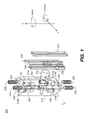
- FIG. 1 there is shown, in an exploded view presentation, component parts of a kinematic optical mount 200 for a reflective element 202.
- a frame 204 supports the reflective element 202 and is kinematically secured against a base member 210 by a magnet 212 that provides an attractive force against a 3-point contact.
- Magnet 212 is seated within a cavity 222.
- Pitch adjustment ball 214a, fixed ball 214b, and yaw adjustment ball 214c are seated in sockets formed on a surface of base member 210 to provide three contact points for the 3-point contact.
- the magnet 212 should be mounted so that its force is concentrated within the triangle formed by the three contact points.
- base member 210 has two alternate mounting surfaces 218a and 218b, either of which can be used for securing base member 210 to a chassis or other body.
- base member 210 allows optical mount 200 to be configured so that it allows pitch and yaw adjustment from either top mounting surface 218a or bottom mounting surface 218b, depending on the orientation from which the adjustment hardware is installed.
- a yaw adjustment cavity 220 extends through base member 210 between top mounting surface 218a and bottom mounting surface 218b and is threaded over at least a portion of its length.
- a pitch adjustment cavity 224 also extends through base member 210 between surfaces 218a and 218b and is threaded over at least a portion of its length.
- a threaded yaw adjustment insert 228 is provided for fitting into the yaw adjustment cavity 220, either from top mounting surface 218a or bottom mounting surface 218b.
- a threaded pitch adjustment insert 230 is provided for fitting into the pitch adjustment cavity 224, either from top mounting surface 218a or bottom mounting surface 218b Both threaded yaw adjustment insert 228 and threaded pitch adjustment insert 230 are adjustment screws in one embodiment.
- the adjustment screws will have a conical taper, typically on the end of the adjustment screws.
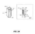
- the partial cutaway view of FIG. 2A shows an embodiment of threaded pitch adjustment insert 230 having a tapered end 238 that sits in contact with pitch adjustment ball 214a to force it outward against frame 204 in a direction D.
- threaded pitch adjustment insert 230 is installed from the top mounting surface 218a.
- the conical tapers push the pitch adjustment ball 214a, and the yaw adjustment ball 214c in or out accordingly, thereby providing the pitch and yaw adjustment for the reflective element 202.
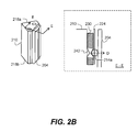
- the conical taper may be provided in the midsection of the adjustment screws, resulting in hour-glass-shaped interior portions.
- This alternate configuration is shown in the embodiment of FIG. 2B , in which threaded pitch adjustment insert 230 has a tapered section 242.
- threaded pitch adjustment insert 230 can be installed from either top or bottom mounting surfaces 218a or 218b.
- An advantage of this arrangement is that the threaded pitch adjustment insert 230 can be adjusted from either top or bottom mounting surfaces 218a or 218b without needing to remove the threaded pitch adjustment insert 230 and insert it from the other direction.
- both ends of the threaded pitch adjustment insert 230 are provided with an adjustment means, such as a screwdriver slot or an Allen wrench head, which can be used to turn the threaded pitch adjustment insert 230 within the pitch adjustment cavity 224.
- the conical or tapered slugs are inserted into the yaw adjustment cavity 220 and the pitch adjustment cavity 224 between the adjustment screws and the balls.
- the adjustment screws push on the conical or tapered slugs, which in turn push the pitch adjustment ball 214a, and the yaw adjustment ball 214c in or out accordingly.
- the yaw adjustment cavity 220 and the pitch adjustment cavity 224 may have a uniform diameter all the way through the base member 210.
- the yaw adjustment cavity 220 and the pitch adjustment cavity 224 can have a larger diameter near one or both mounting surfaces to provide easier access to the yaw adjustment insert 228 and the pitch adjustment insert 230 using adjustment tools such as Allen wrenches. It is particularly advantageous to use a larger diameter cavity when the adjustment inserts are positioned a relatively large distance from the mounting surface. For the example shown in FIG. 1 , it can be seen that the yaw adjustment cavity 220 has a larger diameter toward the bottom mounting surface 218b and the pitch adjustment cavity 224 has a larger diameter toward the top mounting surface 218a.
- the axes of yaw adjustment cavity 220 and the pitch adjustment cavity 224 can be offset relative to the bores for the pitch adjustment ball 214a and the yaw adjustment ball 214c. This will force the adjustment ball to one side of the bore, thereby eliminating possible "hunting" or lost motion during adjustment as the adjustment ball wanders from one side of the bore to another.
- Threaded yaw adjustment insert 228 is shown in both of its possible orientations as it would be threaded into threaded yaw adjustment cavity 220; only one orientation would be used for any single optical mount 200.
- a threaded pitch adjustment insert 230 is shown in both of its possible orientations.
- Mounting holes 240 are also provided on the top mounting surface 218a and the bottom mounting surface 218b. These holes can be used to fasten the optical mount 200 to an external chassis from either the top or bottom directions. Typically, the mounting holes 240 are threaded and the optical mount 200 is fastened to the external chassis using threaded screws.
- threaded yaw adjustment insert 228 adjusts the position of yaw adjustment ball 214c in its socket. This repositioning causes a slight change in the position of the plane formed by the 3-point contact, effecting a slight shift in yaw for frame 204 and the optical component that it supports, here, reflective element 202.
- threaded pitch adjustment insert 230 adjusts the position of ball pitch adjustment ball 214a in its socket. This repositioning also causes a slight change in the position of the plane formed by the 3-point contact, effecting a slight shift in pitch for frame 204 and the optical component that it supports.
- Fixed ball 214b seated in a socket 232, provides a pivot point for both pitch and yaw adjustments.
- a V-channel 234 extending lengthwise along frame 204 provides low-friction contact for yaw rotation of frame 204.
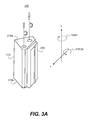
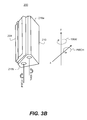
- FIGS. 3A and 3B show how optical mount 200 can be configured to allow pitch and yaw adjustment from either top surface 218a or bottom surface 218b, respectively.
- the threaded yaw adjustment insert 228 and the threaded pitch adjustment insert 230 are inserted from top surface 218a, and the pitch and yaw adjustments can therefore be accessed from the top surface 218a.
- the threaded yaw adjustment insert 228 and the threaded pitch adjustment insert 230 are inserted from bottom surface 218b, and the pitch and yaw adjustments can therefore be accessed from the bottom surface 218b.
- Reflective element 202 is adhesively bonded to frame 204 in one preferred embodiment. Alternatively, some other method of coupling or attachment can be provided for the optical component, including the use of a bracket or fastener, for example. In an alternate embodiment, reflective element 202 is formed directly onto frame 204, rather than being a separate component.
- FIG. 4 shows an alternate embodiment in which a pair of optical mounts 200 are installed back-to-back against a chassis 236 within an optical assembly.
- base member 210 has a broadened mounting surface 218c that has a broadened area for mounting.
- access for pitch and yaw adjustment can be from the direction of the top surface 218a, as viewed in FIG. 3A , or from bottom surface 218c, as viewed in FIG. 3B , again depending on the orientation of threaded yaw adjustment insert 228 and the threaded pitch adjustment insert 230.
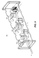
- Optical mount 200 of the present invention is particularly suited for use in an array configuration, such as that shown in cutaway perspective in FIG. 5 .
- a beam alignment chamber 100 has a number of optical mounts 200 installed along a base 110 and along a top cover (removed for clarity). Beam alignment chamber 100 redirects light beams from multiple sources (not shown), each beam source coupled with a corresponding reflector in an optical mount 200, to provide light along an output path A. With this type of arrangement, a separate adjustment is provided for each beam, simplifying the beam alignment task.
- pitch and yaw adjustment for an optical component does not require fixturing and can be configured to be performed from either of two directions without the need for fabricating different sets of components for the different configurations. Adjustment of pitch and yaw can be made over a few degrees in each orthogonal direction and the position maintained due to the magnetic force and three-point mounting that is provided.
- the use of magnetic loading for this kinematic mount helps to reduce the parts count and provides a kinematic loading force that is sufficiently robust for mounting and accurately positioning a mirror or other optical component.
- the base member 210 can be magnetized to provide the attraction force, thereby eliminating the need for magnet 212.
- the magnet 212 can be replaced by a spring or other type of attraction means that provides the kinematic loading force needed to hold the frame 204 tightly against the three contact points. It can be appreciated that other attraction means could be employed in various embodiments, such as gravity, elastic tension, or fluid pressure, for example.
- FIG. 6A An alternate embodiment of the present invention using a spring as the attraction means is shown in the partial cutaway view of Figure 6A , in which an extension spring 244 extends from base member 210 to provide a kinematic loading force F.
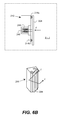
- FIG. 6B Another arrangement using a spring is shown in the partial cutaway view of Figure 6B .
- a compression spring 246 cooperates with an arm 248 that is coupled to frame 210 to provide the loading force F that attracts frame 204 toward base member 210.
- This configuration has the added advantage that it can limit the excursion of the frame 204 during a shock event. This can also prevent the pitch adjustment ball 214a, the fixed ball 214b and the yaw adjustment ball 214c from becoming dislodged during such shock events.
- Base member 210 and frame 204 can be formed of various types of steel or other metals or from ceramics or other materials having suitable magnetic permeability and other properties.
- Base member 210 need not have a high magnetic permeability, but this characteristic can be advantageous for providing an improved flux distribution for providing the kinematic loading when a magnetic attraction means is used.
- Electrical-Discharge Machining (EDM) can be used to fabricate either or both of base member 210 and frame 204.
- Other automated or manual machining methods such as die casting or extrusion can alternately be employed.
- base member 210 can be a magnetic or magnetized material, rather than housing a separate magnet.
- Optical mount 200 can also be configured to support other types of optical elements beside the simple reflective element 202 shown in the preceding examples.
- optical mount 200 can also be configured to support a partially reflective element such as a beam splitter, or a refractive element or some other type of optical element that transmits light.
- the optical mount of the present invention can be used for accurate positioning of an optical component that redirects, filters, reflects, blocks, or transmits light or otherwise conditions incident light.
Landscapes
- Physics & Mathematics (AREA)
- General Physics & Mathematics (AREA)
- Optics & Photonics (AREA)
- Mounting And Adjusting Of Optical Elements (AREA)
Applications Claiming Priority (2)
| Application Number | Priority Date | Filing Date | Title |
|---|---|---|---|
| US12/469,894 US7992835B2 (en) | 2009-05-21 | 2009-05-21 | Kinematic mirror mount adjustable from two directions |
| EP10723375 | 2010-05-20 |
Related Parent Applications (1)
| Application Number | Title | Priority Date | Filing Date |
|---|---|---|---|
| EP10723375.1 Division | 2010-05-20 |
Publications (1)
| Publication Number | Publication Date |
|---|---|
| EP2444830A1 true EP2444830A1 (en) | 2012-04-25 |
Family
ID=42320919
Family Applications (1)
| Application Number | Title | Priority Date | Filing Date |
|---|---|---|---|
| EP11195517A Withdrawn EP2444830A1 (en) | 2009-05-21 | 2010-05-20 | Kinematic mirror mount adjustable from two directions |
Country Status (5)
| Country | Link |
|---|---|
| US (1) | US7992835B2 (enExample) |
| EP (1) | EP2444830A1 (enExample) |
| JP (1) | JP2012527648A (enExample) |
| CN (1) | CN102428400B (enExample) |
| WO (1) | WO2010134990A2 (enExample) |
Families Citing this family (12)
| Publication number | Priority date | Publication date | Assignee | Title |
|---|---|---|---|---|
| CN102928940A (zh) * | 2011-08-11 | 2013-02-13 | 中强光电股份有限公司 | 光学投影系统及其镜片调整装置 |
| US8570675B1 (en) * | 2012-05-02 | 2013-10-29 | Raytheon Company | Kinematic optical device mount |
| CN105259634B (zh) * | 2015-11-17 | 2017-09-12 | 中国科学院长春光学精密机械与物理研究所 | 一种大口径反射镜的whiffletree支撑结构中的两自由度柔节 |
| CN107044619B (zh) * | 2016-02-05 | 2020-09-11 | 深圳光峰科技股份有限公司 | 光斑压缩结构和光源装置 |
| CN113154336B (zh) * | 2016-02-05 | 2022-11-11 | 深圳光峰科技股份有限公司 | 光斑压缩结构和光源装置 |
| CN105610045B (zh) * | 2016-03-25 | 2019-04-05 | 南京大学 | 一种用于激光谐振腔中的温控装置 |
| DE102017126293A1 (de) * | 2017-11-09 | 2019-05-09 | Compact Laser Solutions Gmbh | Vorrichtung zur Verstellung eines optischen Bauelements |
| CN110531572B (zh) * | 2018-05-23 | 2021-05-11 | 中强光电股份有限公司 | 光学元件调整机构及投影装置 |
| EP3739384B1 (en) | 2019-05-17 | 2021-03-17 | Axis AB | A mount for an image capturing device |
| CA3106747A1 (en) * | 2020-01-30 | 2021-07-30 | Thorlabs, Inc. | Transverse drive kinematic optic mount |
| CN112583490B (zh) * | 2020-12-24 | 2025-01-21 | 重庆思柏高科技有限公司 | 光传输传感器装置、传感监控系统及检测方法 |
| CN114046778B (zh) * | 2021-11-16 | 2025-05-30 | 上海迪璞电子科技股份有限公司 | 等距平行激光束发生器、车身视觉检测设备和检测方法 |
Citations (3)
| Publication number | Priority date | Publication date | Assignee | Title |
|---|---|---|---|---|
| US3751139A (en) * | 1971-07-12 | 1973-08-07 | Union Carbide Corp | Optical mounting device for use in laser systems |
| GB2136145A (en) * | 1983-03-03 | 1984-09-12 | Nicolet Instrument Corp | Adjustable mounting for an optical element |
| US20070171553A1 (en) * | 2006-01-20 | 2007-07-26 | Newport Corporation | Adjustable optical mount with locking devices and methods |
Family Cites Families (23)
| Publication number | Priority date | Publication date | Assignee | Title |
|---|---|---|---|---|
| US3407018A (en) * | 1964-01-30 | 1968-10-22 | Electro Optical Systems Inc | Two-axis angular positioning apparatus for adjusting the position of an optical element |
| US3357268A (en) * | 1964-05-01 | 1967-12-12 | Gen Dynamics Corp | Optical cell |
| US3566101A (en) * | 1967-06-22 | 1971-02-23 | Leitz Ernst Gmbh | Centering device |
| US4120586A (en) * | 1977-01-28 | 1978-10-17 | Baxter Travenol Laboratories, Inc. | Method and means for aligning focusing mirrors in an optical spectrometer |
| US4293112A (en) * | 1979-10-29 | 1981-10-06 | Jersey Nuclear-Avco Isotopes, Inc. | Compact mirror mount |
| US4401288A (en) * | 1981-03-13 | 1983-08-30 | Data General Corporation | Adjustable optical mirror mount |
| JPS6092220U (ja) * | 1983-11-30 | 1985-06-24 | ホ−ヤ株式会社 | 煽り装置 |
| US4712444A (en) * | 1986-09-16 | 1987-12-15 | Ball Corporation | Levered optical mount |
| US4925288A (en) * | 1989-05-23 | 1990-05-15 | Coherent, Inc. | Adjustable mirror mount |
| US5048954A (en) * | 1989-07-07 | 1991-09-17 | Miradco | Laser-based wheel alignment system |
| US5004205A (en) * | 1990-06-04 | 1991-04-02 | Rockwell International Corporation | High-range and resolution determinate mount and positioner |
| US5400184A (en) * | 1992-10-29 | 1995-03-21 | The United States Of America As Represented By The United States Department Of Energy | Kinematic high bandwidth mirror mount |
| US5505422A (en) * | 1994-06-02 | 1996-04-09 | Bio-Rad Laboratories | Top adjustable kinematic mount |
| US5798879A (en) * | 1995-06-07 | 1998-08-25 | Salvio; Paul R. | Stress-free, adjustable optical support |
| US6053469A (en) * | 1995-11-08 | 2000-04-25 | General Scanning, Inc. | Low-cost 2-axis mirror mount |
| GB0005814D0 (en) * | 2000-03-11 | 2000-05-03 | Renishaw Plc | Mounting for optical components |
| US6568647B2 (en) * | 2001-01-25 | 2003-05-27 | Aoptix Technologies, Inc. | Mounting apparatus for a deformable mirror |
| JP2002335047A (ja) | 2001-05-10 | 2002-11-22 | Hamamatsu Photonics Kk | 半導体レーザ装置 |
| US6943957B2 (en) | 2001-08-10 | 2005-09-13 | Hamamatsu Photonics K.K. | Laser light source and an optical system for shaping light from a laser-bar-stack |
| US6543740B2 (en) * | 2001-09-04 | 2003-04-08 | National Research Council Of Canada | Mechanism for transmitting movement in up to six degrees-of-freedom |
| US7268960B2 (en) * | 2005-11-04 | 2007-09-11 | Plx, Inc. | Mount for an optical structure and method of mounting an optical structure using such mount |
| US7688528B2 (en) * | 2006-08-14 | 2010-03-30 | Newport Corporation | Mount for optical component having independent multi-axial control |
| JP4963071B2 (ja) * | 2007-03-07 | 2012-06-27 | 株式会社 ファースト メカニカル デザイン | 光学素子ホルダ |
-
2009
- 2009-05-21 US US12/469,894 patent/US7992835B2/en not_active Expired - Fee Related
-
2010
- 2010-05-20 EP EP11195517A patent/EP2444830A1/en not_active Withdrawn
- 2010-05-20 CN CN201080021801.6A patent/CN102428400B/zh not_active Expired - Fee Related
- 2010-05-20 WO PCT/US2010/001492 patent/WO2010134990A2/en not_active Ceased
- 2010-05-20 JP JP2012511824A patent/JP2012527648A/ja active Pending
Patent Citations (3)
| Publication number | Priority date | Publication date | Assignee | Title |
|---|---|---|---|---|
| US3751139A (en) * | 1971-07-12 | 1973-08-07 | Union Carbide Corp | Optical mounting device for use in laser systems |
| GB2136145A (en) * | 1983-03-03 | 1984-09-12 | Nicolet Instrument Corp | Adjustable mounting for an optical element |
| US20070171553A1 (en) * | 2006-01-20 | 2007-07-26 | Newport Corporation | Adjustable optical mount with locking devices and methods |
Also Published As
| Publication number | Publication date |
|---|---|
| CN102428400A (zh) | 2012-04-25 |
| WO2010134990A3 (en) | 2011-01-20 |
| US20100296188A1 (en) | 2010-11-25 |
| US7992835B2 (en) | 2011-08-09 |
| CN102428400B (zh) | 2014-06-04 |
| JP2012527648A (ja) | 2012-11-08 |
| WO2010134990A2 (en) | 2010-11-25 |
| WO2010134990A4 (en) | 2011-04-07 |
Similar Documents
| Publication | Publication Date | Title |
|---|---|---|
| US7992835B2 (en) | Kinematic mirror mount adjustable from two directions | |
| US10670825B2 (en) | Mounting devices with integrated alignment adjustment features and locking mechanisms | |
| US6754013B2 (en) | Adjustable mount for optical components | |
| EP2335109B1 (en) | Ball bearing mirror mount | |
| US9323025B2 (en) | Kinematic mount | |
| WO1991006022A1 (en) | Mounting optical components | |
| USRE46564E1 (en) | Kinematic optical device mount | |
| JP2013161050A (ja) | 光学素子ホルダ | |
| JP4905091B2 (ja) | ミラー取付構造 | |
| US11029485B2 (en) | Optical mount | |
| CN110226322A (zh) | 模块化光学拍摄系统 | |
| EP1308765B1 (en) | Mount for ultra-high performance of optical components under thermal and vibrational distortion conditions | |
| US5798879A (en) | Stress-free, adjustable optical support | |
| EP1817619B1 (en) | Optical mounting for position adjustment in six degrees of freedom | |
| EP0542799A1 (en) | Optical component holder | |
| US10996419B2 (en) | Thermal compensating optical component mount and related devices | |
| JPH06500867A (ja) | 位置決め装置 | |
| JP2007322709A (ja) | 光学部材支持機構、光学装置、および間隔調整部材 | |
| US6590723B1 (en) | Optical instrument mount | |
| CN217097414U (zh) | 一种可调节透镜位置的夹具 | |
| JP2001281514A (ja) | 光学要素保持機構および該光学要素保持機構を含む光学機器 | |
| JPH0289662A (ja) | 光学装置 | |
| JP6687268B1 (ja) | 光学部品の調整構造及び光学装置 | |
| GB2573087A (en) | Improvements in or relating to optical components | |
| US20100128368A1 (en) | Z-Translation Mechanics; the Z-translating optical electro-mechanical allignment system |
Legal Events
| Date | Code | Title | Description |
|---|---|---|---|
| AK | Designated contracting states |
Kind code of ref document: A1 Designated state(s): AL AT BE BG CH CY CZ DE DK EE ES FI FR GB GR HR HU IE IS IT LI LT LU LV MC MK MT NL NO PL PT RO SE SI SK SM TR |
|
| AX | Request for extension of the european patent |
Extension state: BA ME RS |
|
| PUAI | Public reference made under article 153(3) epc to a published international application that has entered the european phase |
Free format text: ORIGINAL CODE: 0009012 |
|
| RIN1 | Information on inventor provided before grant (corrected) |
Inventor name: BRIDGES, MARK EDWARD Inventor name: HARLAND, MARC A. |
|
| STAA | Information on the status of an ep patent application or granted ep patent |
Free format text: STATUS: THE APPLICATION IS DEEMED TO BE WITHDRAWN |
|
| 18D | Application deemed to be withdrawn |
Effective date: 20121026 |