EP2444824A2 - Strahlungsdetektor, Röntgenbilderfassungssystem, Strahlungserkennungsverfahren, Speichermedium für Strahlungserkennungsprogramm und Steuergerät - Google Patents
Strahlungsdetektor, Röntgenbilderfassungssystem, Strahlungserkennungsverfahren, Speichermedium für Strahlungserkennungsprogramm und Steuergerät Download PDFInfo
- Publication number
- EP2444824A2 EP2444824A2 EP11184834A EP11184834A EP2444824A2 EP 2444824 A2 EP2444824 A2 EP 2444824A2 EP 11184834 A EP11184834 A EP 11184834A EP 11184834 A EP11184834 A EP 11184834A EP 2444824 A2 EP2444824 A2 EP 2444824A2
- Authority
- EP
- European Patent Office
- Prior art keywords
- image
- radiation
- radiographic image
- pixels
- radiographic
- Prior art date
- Legal status (The legal status is an assumption and is not a legal conclusion. Google has not performed a legal analysis and makes no representation as to the accuracy of the status listed.)
- Granted
Links
Images



Classifications
-
- A—HUMAN NECESSITIES
- A61—MEDICAL OR VETERINARY SCIENCE; HYGIENE
- A61B—DIAGNOSIS; SURGERY; IDENTIFICATION
- A61B6/00—Apparatus or devices for radiation diagnosis; Apparatus or devices for radiation diagnosis combined with radiation therapy equipment
- A61B6/54—Control of apparatus or devices for radiation diagnosis
- A61B6/548—Remote control of the apparatus or devices
-
- H—ELECTRICITY
- H04—ELECTRIC COMMUNICATION TECHNIQUE
- H04N—PICTORIAL COMMUNICATION, e.g. TELEVISION
- H04N23/00—Cameras or camera modules comprising electronic image sensors; Control thereof
- H04N23/30—Cameras or camera modules comprising electronic image sensors; Control thereof for generating image signals from X-rays
Definitions
- the present invention pertains to a radiation detector, a radiographic image capturing system, a radiation detection method, a radiation detection program storage medium, and a controller and particularly relates to a radiation detector, a radiographic image capturing system, a radiation detection method, a radiation detection program storage medium, and a controller that capture a radiographic image without having to synchronize with a radiation application action of a radiation applicator.
- radiographic image capturing systems that perform radiographic imaging for the purpose of medical diagnoses have been known.
- a radiographic image capturing system there is a radiographic image capturing system that is equipped with a radiation applicator that applies radiation, a radiation detector—such as what is known as a cassette—that detects the radiation that has passed through a subject to capture a radiographic image, and a controller that controls the radiation applicator and the radiation detector.
- the FPD performs initialization of the solid-state imaging device and, after the initialization has been completed, transmits an imaging preparation completion signal to the radiation applicator.
- the radiation applicator After the radiation applicator receives the imaging preparation completion signal, the radiation applicator starts the application of the radiation, ends the application of the radiation after a preset application time has elapsed, and transmits an application end signal to the FPD.
- the FPD receives the application end signal, the FPD ends a charge storage action by the solid-state imaging device and transitions to an output action in which the FPD outputs image data of the detected radiographic image to the controller.
- JP-A Japanese Patent Application Laid-Open Nos. 2005-13272 and 2003-307569 disclose technologies in which the timing of the application of the radiation is determined by the FPD.
- a radiation detector has been proposed that determines an application timing, which is the timing of the application of the radiation that is applied from the radiation applicator in order to capture a radiographic image of a subject, when charge information (electrical signals) that has been read out from the solid-state imaging device has reached a predetermined threshold value or greater.
- the radiation detector may capture a radiographic image (detect image data) at a wrong timing that is originally not a correct (intended) timing when the radiation detector is to capture a radiographic image of the subject.
- the present invention provides a radiation detector, a radiographic image capturing system, a radiation detection method, a radiation detection program storage medium, and a controller that can determine whether or not a radiographic image is an image that has been detected at a correct (intended) timing.
- a first aspect of the present invention is a radiation detector including: a detecting means that detects image data of a radiographic image by plural pixels that convert applied radiation into electrical signals and store the electrical signals; a detection controlling means that controls the detecting means so as to determine that radiation has been applied if a read value obtained by reading the electric signals stored in the plural pixels is equal to or greater than a threshold value and acquire image data of a radiographic image corresponding to radiation that has passed through a subject; an image analyzing means that performs an image analysis with respect to the radiographic image based on the detected image data if the read value is equal to or greater than the threshold value; and a determining means that determines on the basis of the result of the image analysis whether or not the radiographic image is an image that has been detected at an intended timing.
- the image analyzing means performs the image analysis with respect to the radiographic image based on the image data that have been detected by the detecting means if the read value obtained by reading the electrical signals stored in the pixels is equal to or greater than the threshold value.
- the determining means determines on the basis of the result of the image analysis by the image analyzing means whether or not the radiographic image is an image that has been detected at a correct (intended) timing.
- the radiation detector detects a radiographic image at an unintended timing that is not an intended timing. For example, if the radiation detector being dropped or given a shock, a radiographic image is captured even though it is not a timing when the radiation detector is to capture a radiographic image (an intended timing).
- the image analyzing means performs the image analysis with respect to the radiographic image based on the image data that have been detected by the detecting means if the read value obtained by reading the electrical signals stored in the pixels is equal to or greater than the threshold value. Therefore, it can be determined on the basis of the result of the image analysis whether or not the radiographic image is an image that has been detected at an intended timing.
- the radiation detector may further include an output means that outputs the image data to the outside; and an output controlling means that controls the output means so as to prevent outputting of the image data to the outside if the determining means has determined that the radiographic image is not an image that has been detected at an intended timing.
- the image analyzing means may perform the image analysis using a mean value of pixel values of a predetermined number of pixels of the radiographic image.
- the image analyzing means may perform the image analysis on the basis of a difference between a mean value of pixel values of a predetermined number of pixels of the radiographic image and a mean value of pixel values of a predetermined number of pixels of a radiographic image that has been detected at an intended timing.
- processing time for the image analysis can be shortened compared to a case in which, for example, a histogram analysis is performed.
- the predetermined number of pixels may be all pixels of the radiographic image or pixels in a predetermined region of the radiographic image.
- the image analyzing means By configuring the image analyzing means to use the predetermined number of pixels in a predetermined region of the radiographic image, processing time for the image analysis can be shortened even more compared to a case in which all pixels are used.
- the detection controlling means may control the detecting means in a case in which imaging conditions of a radiographic image of the subject have been registered from the outside.
- the radiation detector In a case in which imaging conditions have been registered from the outside, if the radiation detector, in which the detection controlling means determines that radiation has been applied and controls the detecting means, outputs to the outside image data of a radiographic image that is not an image that has been detected at an intended timing, the user must register again the imaging conditions for retaking. In such radiation detector, by performing control so as to prevent output to the outside image data of a radiographic image that is not an image that has been detected at an intended timing, the waste of having to re-register the imaging conditions can be eliminated.
- a second aspect of the present invention is a radiographic image capturing system including: a controller that instructs imaging conditions relating to capturing a radiographic image; a radiation applicator that applies radiation on the basis of an instruction from the controller; and the radiation detector according to the first aspect, which detects image data of a radiographic image corresponding to the radiation that has been applied from the radiation applicator and outputs the image data to the controller.
- a third aspect of the present invention is a radiation detection method including: reading, with a detecting means that detects image data of a radiographic image by plural pixels that convert applied radiation into electrical signals and store the electrical signals, the electrical signals stored in the plural pixels; determining that radiation has been applied if a read value obtained by the reading is equal to or greater than a threshold value and controlling the detecting means so as to acquire image data of a radiographic image corresponding to radiation that has passed through a subject; performing an image analysis with respect to the radiographic image based on the detected image data if the read value is equal to or greater than the threshold value; and determining on the basis of the result of the image analysis whether or not the radiographic image is an image that has been detected at an intended timing.
- a fourth aspect of the present invention is non-transitory storage medium storing a program causing a computer to execute radiation detection processing, the radiation detection processing including: reading, with a detecting means that detects image data of a radiographic image by plural pixels that convert applied radiation into electrical signals and store the electrical signals, the electrical signals stored in the plurality of pixels; determining that radiation has been applied if a read value obtained by the reading is equal to or greater than a threshold value and controlling the detecting means so as to acquire image data of a radiographic image corresponding to radiation that has passed through a subject; performing an image analysis with respect to the radiographic image based on the detected image data if the read value is equal to or greater than the threshold value; and determining on the basis of the result of the image analysis whether or not the radiographic image is an image that has been detected at an intended timing.
- a fifth aspect of the present invention is a controller including: a receiving unit that receives image data that have been outputted from a radiation detector that reads electric signals from plural pixels that convert applied radiation into electrical signals and store the electrical signals, determines that radiation has been applied if a read value of the electrical signals is equal to or greater than a threshold value, and detects image data; an image analyzing means that performs an image analysis with respect to the radiographic image based on the received image data; and a determining means that determines on the basis of the result of the image analysis whether or not the radiographic image is an image that has been detected at an intended timing.
- a radiographic image is an image that has been detected at an intended timing.
- FIG. 1 shows the schematic configuration of a radiographic image capturing system 10 of the present exemplary embodiment.
- the radiographic image capturing system 10 is equipped with a radiation applicator 16 that applies radiation (e.g., X-rays) to a subject 19, a radiation detector 14 that detects the radiation that has been applied from the radiation applicator 16 and has passed through the subject 19, and a controller (console) 12 that instructs the capture of a radiographic image, acquires image data from the radiation detector 14, and performs various processings.
- the radiation that carries image information as a result of being applied from the radiation applicator 16 and passing through the subject 19 positioned in an imaging position is applied to the radiation detector 14.
- the controller 12 is wirelessly connected to the radiation detector 14 and executes various controls with respect to the radiation detector 14 by wirelessly transmitting commands and data via a communication interface (I/F) 26.
- the controller 12 is also wirelessly connected to the radiation applicator 16 and controls the timing when the radiation applicator 16 applies the radiation (e.g., X-rays).
- the controller 12 is equipped with a central processing unit (CPU) 20, a memory 22, a processor 24, a display unit 25, and the communication I/F 26.
- the CPU 20, the memory 22, the processor 24, the display unit 25, and the communication I/F 26 are interconnected by a bus 28 such as a CPU bus so as to be capable of sending signals to and receiving signals from each other.
- the CPU 20 controls the actions of the entire controller 12 by executing various programs that are stored beforehand in the memory 22.
- the processor 24 acquires the image data from the radiation detector 14 and performs various processings.
- the display unit 25 displays, for example, the radiographic image received via the communication I/F 26 from the radiation detector 14.
- the radiation applicator 16 is equipped with a radiation source 17 and a communication interface (I/F) 18.
- the radiation applicator 16 is wirelessly connected to the controller 12 via the communication I/F 18 and applies the radiation from the radiation source 17 to the subject 19 at a timing based on the control of the controller 12.
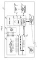
- FIG 2 is a functional block diagram showing an example of the configuration of the radiation detector 14.
- the radiation detector 14 is a radiation detection panel unit, and examples thereof include flat panel detectors (FPD) and what are known as cassettes.
- FPD flat panel detectors
- the radiation detector 14 is equipped with a thin-film transistor (TFT) unit 30, a charge amplifier/multiplexer (MUX) 32, an analog-to-digital (A/D) converter 34, a control unit 36, a gate driver 38, a wireless communication unit 40, a storage unit 42, an image analyzing unit 44, and a power source unit 48.
- TFT thin-film transistor
- MUX charge amplifier/multiplexer
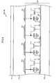
- FIG. 3 is a cross-sectional view schematically showing an example of the configuration of the TFT unit 30.
- the TFT unit 30 includes a TFT substrate 54 in which switch elements 52 such as TFTs are formed on an insulating substrate 50.
- the switch elements 52 are connected to gate lines 68 for switching on and off the switch elements 52.
- a scintillator layer 56 that converts the radiation made incident thereon into light is formed on the TFT substrate 54.
- the scintillator layer 56 for example, a CsI:T1 or GOS (Gd 2 O 2 S:Tb) phosphor or the like can be used.
- the scintillator layer 56 is not limited to these materials.
- the insulating substrate 50 for example, a glass substrate, various types of ceramic substrates, a resin substrate, or the like can be used, but the insulating substrate 50 is not limited to these materials.
- Photoconductive layers 58 are placed between the scintillator layer 56 and the TFT substrate 54.
- the photoconductive layers 58 generates charges when the light into which the radiation has been converted by the scintillator layer 56 is made incident thereon.
- Bias electrodes 60 for applying a bias voltage to the photoconductive layers 58 are disposed on the surfaces of the photoconductive layers 58 on the scintillator layer 56 side.
- Charge collecting electrodes 62 for collecting the charges generated by the photoconductive layers 58 are disposed on the TFT substrate 54. In the TFT substrate 54, the charges collected by the charge collecting electrodes 62 are read out by the switch elements 52.
- the charge collecting electrodes 62 are arranged in a matrix (two-dimensionally) on the TFT substrate 54.
- the switch elements 52 are arranged in a matrix on the insulating substrate 50.
- a planarizing layer 64 for planarizing the top surface of the TFT substrate 54 is formed on the TFT substrate 54.
- an adhesive layer 66 for adhering the scintillator layer 56 to the TFT substrate 54 is formed on the planarizing layer 64.
- the radiation may be applied to the radiation detector 14 from the front side on which the scintillator layer 56 is adhered (i.e., the front side is the imaging surface) or may be applied to the radiation detector 14 from the TFT substrate 54 side (back side) (i.e., the back side is the imaging surface).
- the radiation is applied to the radiation detector 14 from the front side
- light emission at the upper surface side (the opposite side of the TFT substrate 54 side) of the scintillator layer 56 is relatively strong.
- the radiation that has passed through the TFT substrate 54 is made incident on the scintillator layer 56, and light emission at the TFT substrate 54 side of the scintillator layer 56 is relatively strong.
- the sensitivity of the radiation detector 14 with respect to the radiation can be set higher in the case in which the radiation is applied from the front side than in the case in which the radiation is applied from the back side, because the radiation does not pass through the TFT substrate 54 in the case in which the radiation is applied from the front side.
- the resolution of the radiographic image obtained by the imaging is higher in the case in which the radiation is applied from the back side than in the case where the radiation is applied from the front side, because the light emission position of the scintillator layer 56 with respect to the photoconductive layers 58 is closer in the case in which the radiation is applied from the back side.
- the structure and so forth of the TFT unit 30 is not limited to this.
- the TFT unit 30 may also take another structure as long as it has the function of storing and outputting charges corresponding to the radiation that has been applied to the radiation detector 14.
- FIG. 4 shows an example of another structure of the TFT unit 30.
- FIG. 4 is a cross-sectional view schematically showing another example of the configuration of the TFT unit 30.
- the TFT unit 30 shown in FIG. 4 employs a direct conversion structure that directly converts radiation into charges with a sensor unit using amorphous selenium or the like and stores the charges.
- a photoconductive layer 59 that converts the radiation made incident thereon into charges is formed on the TFT substrate 54.
- a bias electrode 61 is formed on the front surface of the photoconductive layer 59, which is for applying a bias voltage to the photoconductive layer 59.
- the charge collecting electrodes 62 that collect the charges generated by the photoconductive layer 59 are formed on the TFT substrate 54.
- the TFT substrate 54 in the direct conversion TFT unit 30 is equipped with charge storage capacitors 63 that store the charges collected by the charge collecting electrodes 62.
- the charges stored in the charge storage capacitors 63 are read out by the switch elements 52.
- a QL value information relating to the charges (charge information) that have been read out from the TFT unit 30 is called.
- the charges that have been read out in the TFT unit 30 are outputted to the charge amplifier/MUX 32 as electrical signals.
- the charge amplifier 32 amplifies the electrical signals and converts the amplified electrical signals into analog voltages in the form of electrical information (data).
- the charge amplifier 32 is configured by an amplification circuit and a sample-and-hold circuit using operational amplifiers and capacitors.
- the electrical signals held in the sample-and-hold circuit undergo parallel-to-serial conversion in the MUX 32 and are outputted to the A/D converter 34.
- the A/D converter 34 converts the serially inputted analog voltages into digital signals that are easier to handle.
- the two-dimensional image data of the radiographic image converted into the digital signals by the A/D converter 34 are outputted to the control unit 36.
- an image memory (not shown in the drawings) is connected to the A/D converter 34, and the transmitted image data are stored in sequence in the image memory.
- the image memory has a storage capacity capable of storing a predetermined number of frames' worth of image data, and each time the capture of a radiographic image is performed, the image data obtained by the imaging are sequentially stored in the image memory.
- the control unit 36 is configured by a microcomputer, includes a CPU 36A, a memory 36B including a ROM and a RAM, and a nonvolatile storage unit 36C formed of a flash memory or the like.
- the control unit 36 controls the actions of the entire radiation detector 14 by executing, with the CPU 36A, various programs stored in the memory 36B.
- the control unit 36 performs control of reading the storage quantity of the charges (electrical signals) stored in the TFT unit 30 intermittently after an imaging menu is registered, determining whether or not the read charge storage quantity is equal to or greater than a threshold value stored in the storage unit 36C, and, if the charge storage quantity is equal to or greater than the threshold value, determining that the timing is an imaging timing when radiation has been applied from the radiation applicator 16, starting capture of a radiographic image of the subject 19, and acquiring image data (details described later).
- the control unit 36 may determine the imaging timing by reading out the storage quantity of the charges stored in predetermined pixels or dedicated pixels, determining the timing is an imaging timing is the read value of the charges has exceeded a predetermined threshold value, and performing imaging.
- control unit 36 may simultaneously read out the storage quantity of the charges stored in the pixels in plural row units, determine that the timing is an imaging timing if the read value of the charges has exceeded a predetermined threshold value, and perform imaging.
- control unit 36 may be configured to simultaneously read out the charge storage quantity in predetermined row intervals. In either method, it is preferred that the control unit 36 perform a reset action in which it resets the charges stored until then just before starting charge storage for capturing a radiographic image.
- the control unit 36 determines on the basis of the result of an image analysis by the image analyzing unit 44 whether the radiographic image is a radiographic image that has been captured at an intended timing or a radiographic image that has been captured at an unintended timing when it is not intended to perform imaging in the radiation detector 14. If the radiographic image has been captured at an unintended timing, control unit 36 controls the wireless communication unit 40 so as to prevent output of the image data of the radiographic image to the controller 12 (details described later).
- the image data of the radiographic image are further transmitted from the control unit 36 to the image analyzing unit 44.
- the image analyzing unit 44 performs an image analysis of the radiographic image on the basis of the image data and outputs the result of the image analysis to the control unit 36.
- the image data are further transmitted from the control unit 36 to the wireless communication unit 40.
- the wireless communication unit 40 wirelessly transmits in packets the image data per line.
- the wireless communication unit 40 performs wireless communication with an external device (here, the controller 12), is adapted to a wireless LAN standard represented by IEEE (Institute of Electrical and Electronics Engineers) 802.11a/b/g/n or the like, and controls the transmission of various types of data between the radiation detector 14 and the external device by wireless communication.
- IEEE Institute of Electrical and Electronics Engineers
- the control unit 36 can perform wireless communication with an external device that controls general operation of radiographic image capturing, such as the controller 12, and can transmit various types of data to and receive various types of data from the controller 12.
- an external device that controls general operation of radiographic image capturing
- the control unit 36 registers in the storage unit 42 various types of data such as information of the subject 19 and imaging conditions (imaging menu) received via the wireless communication unit 40 from the controller 12 and performs read-out of the charges on the basis of the registered imaging menu.
- the capture of a radiographic image corresponding to the applied radiation is performed in the radiation detector 14.
- the capturing action of a radiographic image by the radiation detector 14 is executed without receiving an instruction to capture a radiographic image from the controller 12 and without being synchronized with the application of the radiation by the radiation applicator 16.
- the radiation detector 14 is equipped with the power source unit 48.
- Each of the components described above operates on electrical power supplied from the power source unit 48.
- the power source unit 48 has a built-in battery (a rechargeable secondary battery) so as to not impair the portability of the radiation detector 14, and the power source unit 48 supplies the electrical power to the components from the charged battery.
- FIG. 2 illustration of wires connecting the components to the power source unit 48 is omitted in order to prevent the drawing from becoming complicated.
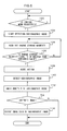
- FIG. 5 is a flowchart showing an example of a flow of radiographic image capturing processing that is executed in the radiation detector 14.
- a program stored beforehand in a predetermined area of the memory 36B is executed by the CPU 36A in the control unit 36.
- step 100 the control unit 36 determines whether or not an imaging menu has been registered. If the radiation detector 14 has not yet received an imaging menu from the controller 12, the determination in step 100 is NO and the control unit 36 stands by. If an imaging menu has been registered, the determination in step 100 is YES and the processing advances to step 102. In step 102, the control unit 36 instructs the TFT unit 30 to start detecting the radiographic image (charge information), that is, to start storing the charges.
- the control unit 36 reads out the charge storage quantity.
- the control unit 36 determines whether or not the read charge storage quantity is equal to or greater than the threshold value stored in the storage unit 36C of the control unit 36. If the read charge storage quantity is less than the threshold value, the processing returns to step 104 and repeats the reading-out of the charge storage quantity and the determination of whether or not the charge storage quantity is equal to or greater than the threshold value. In contrast, if the charge storage quantity is equal to or greater than the threshold value, the determination in step 106 is YES, the control unit 36 determines that application of the radiation has been started, and the processing advances to step 108 in order to start capturing a radiographic image.
- step 108 a reset action is performed in which the charges stored in the TFT unit 30 are discharged. Thereafter, the processing advances to step 110 at which the control unit detects the image data of the radiographic image in the way described above and thereby performs radiographic image capture. Thus, the image data of the radiographic image are acquired.
- the image analyzing unit 44 performs an image analysis of the radiographic image that has been captured.
- the image analyzing unit 44 performs a predetermined image analysis with respect to the radiographic image.
- the image analyzing unit 44 calculates a mean value of pixel values of plural pixels of the radiographic image.
- the plural pixels used in the image analysis may be all pixels of the radiographic image or may also, for example, be plural pixels in a predetermined region such as a head region or a center region.
- a mean value of pixel values of plural pixels of a radiographic image in which the subject 19 has been captured (a mean value of a correct radiographic image) may be acquired beforehand and stored in the storage unit 42, and the image analyzing unit 44 may be configured to find the difference between the mean value of the pixel values of the plural pixels of the radiographic image calculated in the way described above and the mean value of pixel values of plural pixels of the correct radiographic image.
- a histogram of a radiographic image in which the subject 19 has been captured (a histogram of a correct radiographic image) may also be obtained beforehand, and the image analyzing unit 44 may be configured to analyze the deviation between the histogram of the radiographic image that has been captured and the histogram of the correct radiographic image.
- a radiographic image that is obtained as a result is clearly different from a correct (intended) radiographic image.
- the radiation detector has performed imaging in a state in which no radiation is being applied and the charge storage quantity is small, an image similar to a radiographic image of an offset image captured by the radiation detector may be obtained, or a radiographic image captured in a state in which charges have been stored only for a while immediately after the radiation detector has applied the shock may be obtained.
- the resultant image will be clearly different from a correct radiographic image, even without performing a histogram analysis, whether or not the radiographic image is an unintended image can be appropriately determined using the mean value of pixel values of plural pixels of the radiographic image. It is preferable to employ for the image analysis a method using the mean value of pixel values of plural pixels of the radiographic image because the amount of processing time can be shortened.
- the control unit 36 determines based on the result of the image analysis by the image analyzing unit 44 whether the radiographic image is an intended image that has been captured at an intended timing or an unintended image that has been captured at an unintended timing.
- Examples of methods by which the control unit 36 determines whether or not the radiographic image is an intended image based on the result of the image analysis may include a method in which mean values of plural pixels of unintended images are obtained beforehand, a range of mean values regarded as an unintended image is stored in the storage unit 42, and the control unit 36 determines whether or not the radiographic image is an intended image by whether or not the mean value of the plural pixels of the radiographic image that has been obtained as a result of the image analysis in the image analyzing unit 44 is within the range.
- Another example is a method in which a range of differences between mean values of plural pixels of radiographic images serving as references of wrong (unintended) images and mean values of correct (intended) radiographic images is obtained beforehand, the range of differences is stored in the storage unit 42, and the control unit 36 determines whether or not the radiographic image is an intended image by whether or not the difference of the mean value that has been obtained as a result of the image analysis in the image analyzing unit 44 is within the range.
- Yet another example is a method in which the control unit 36 determines whether or not the radiographic image is a correct image by a deviation with the histogram of a correct (intended) image. The method used for the determination by the control unit 36 can be determined in accordance with the image analyzing method of the image analyzing unit 44.
- the determination in step 114 is YES, and the control unit 36 advances to step 116 at which the image data of the radiographic image is output to the controller 12 via the wireless communication unit 40. Thereafter, the processing ends.
- the determination in step 114 is NO, and the processing ends without outputting the image data of the radiographic image to the controller 12.
- the methods for preventing output of the subject image data to the controller 12 may include transmitting the image data of the radiographic image to the wireless communication unit 40 only if the control unit 36 has determined that the radiographic image is an intended image, or transmitting the image data of the radiographic image to the wireless communication unit 40 regardless of whether or not the radiographic image is an intended image and, if the radiographic image is an unintended image, instructing by the control unit 36 the wireless communication unit 40 not to output the image data of the transmitted radiographic image.
- the image data of a radiographic image that has been determined as being an unintended image may be disposed of or may be stored in the storage unit 42 together with an indication that the image is an unintended image. In a case in which the subject image data have been disposed of, only an indication of the fact that an unintended image has been captured may be stored in the storage unit 42.
- the wireless communication unit 40 does not output anything with respect to the controller 12 in a case in which the control unit 36 has determined that the radiographic image is a wrong image.
- the wireless communication unit 40 may be configured to output to the controller 12 an indication that an unintended image has been captured.
- the radiation detector 14 of the radiographic image capturing system 10 determines that radiation has been applied without synchronizing with the radiation application action of the radiation applicator 16.
- the control unit 36 reads out the charge storage quantity of the pixels of the TFT unit 30. If the charge storage quantity that the control unit 36 has read out is equal to or greater than the threshold value stored in the storage unit 36C, the control unit 36 determined that radiation has been applied and performs radiographic image capture.
- the image analyzing unit 44 analyzes the captured radiographic image, and the control unit 36 determines based on the result of the image analysis whether the radiographic image is an intended image that has been captured at an intended timing or an unintended image that has been captured at an unintended timing when it is not supposed to perform imaging.
- the control unit 36 controls the wireless communication unit 40 so as to prevent transmission of the image data of the unintended image to the controller 12.
- the image capturing system 10 (radiation detector 14) can determine whether or not the radiographic image that has been captured is an image that has been detected at an intended timing.
- the radiation detector 14 determined whether or not the radiographic image is an image that has been detected at an intended timing even if the radiation detector 14 has captured a radiographic image at an unintended timing such as, for example, when the radiation detector 14 has misjudged that radiation has been applied due to being dropped or applied a shock and captured a radiographic image. If the radiographic image is a radiographic image that has been detected at an unintended timing, prevents the image data from being outputted to the outside, and therefore, unnecessary image transmission does not occur because the image data are not transmitted to the controller 12. Further, in this way, because an unintended image is not transmitted to the controller 12, the imaging does not being regarded as having ended (the imaging menu does not being regarded as having been completed), and re-registration of the imaging menu for retaking will be unnecessary.
- the image analyzing unit 44 performs the image analysis using the mean value of plural pixels of the radiographic image, whereby processing time can be shortened compared to a case in which a histogram analysis or the like is performed.
- the radiographic image capturing system 10 equipped with one radiation detector 14 has been described, but the radiographic image capturing system is not limited to this and may also, as shown in FIG. 6 , be a radiographic image capturing system 70 equipped with plural (n number in FIG. 6 ) radiation detectors 14.
- the radiation may be applied also to another radiation detector 14 2 installed near the radiation detector 14 that is to perform imaging.
- the radiation detector 14 2 that has detected the radiation performs radiographic image capture and acquires an unintended image regardless of the fact that the timing is originally not the timing when the radiation detector 14 is to perform imaging.
- the radiation detector 14 (14 2 ) can determine based on the image analysis of the radiographic image whether the radiographic image is an unintended image or an intended image, and if it is determined that the radiographic image is an unintended image, the radiation detector 14 can prevent outputting the image data of the unintended image to the controller 12. Therefore, a waste of transmission time can be eliminated and the processing time of the workflow from the start of radiographic image capture to until the completion of output of a correct image (reception by the controller 12 is shortened, whereby convenience improves. Further, since the controller 12 receives only an intended image, the image display speed in the controller 12 can be prevented from becoming slow.
- the exemplary embodiment describes above an example in which the image analysis is performed by the image analyzing unit 44 located in the radiation detector 14.
- the image analysis may be performed by the controller 12.
- processing time will be relatively consumed because even the image data of an unintended image is transmitted from the radiation detector 14 to the controller 12.
- the waste of re-registering the imaging menu can be eliminated by performing a determination of whether or not the imaging has ended (the imaging menu has been completed) in accordance with a determination of whether or not the radiographic image is an unintended image or an intended image performed by an image analyzing unit in the controller 12.
- the controller 12 may transmit a signal indicating this to the radiation detector 14 and the radiation detector 14 may prepare to perform imaging again in the same conditions, or the same imaging menu may be again registered with respect to the radiation detector 14 from the controller 12 as if it were a new order.
- the radiation detector 14 is configured to perform imaging again in the same conditions.
- the configurations and so forth of the radiographic image capturing system 10, the controller 12, the radiation detector 14, the radiation applicator 16, and so forth described in the present exemplary embodiment are examples and are capable of being changed depending on the situation without departing from the gist of the present invention.
- FIG. 5 the example of the flow of the imaging processing described in the present exemplary embodiment ( FIG. 5 ) is also an example and is capable of being changed depending on the situation without departing from the gist of the present invention.
Landscapes
- Health & Medical Sciences (AREA)
- Engineering & Computer Science (AREA)
- Life Sciences & Earth Sciences (AREA)
- Medical Informatics (AREA)
- Optics & Photonics (AREA)
- Biomedical Technology (AREA)
- Biophysics (AREA)
- High Energy & Nuclear Physics (AREA)
- Signal Processing (AREA)
- Nuclear Medicine, Radiotherapy & Molecular Imaging (AREA)
- Multimedia (AREA)
- Pathology (AREA)
- Radiology & Medical Imaging (AREA)
- Physics & Mathematics (AREA)
- Heart & Thoracic Surgery (AREA)
- Molecular Biology (AREA)
- Surgery (AREA)
- Animal Behavior & Ethology (AREA)
- General Health & Medical Sciences (AREA)
- Public Health (AREA)
- Veterinary Medicine (AREA)
- Apparatus For Radiation Diagnosis (AREA)
- Measurement Of Radiation (AREA)
Applications Claiming Priority (1)
| Application Number | Priority Date | Filing Date | Title |
|---|---|---|---|
| JP2010234579A JP5208180B2 (ja) | 2010-10-19 | 2010-10-19 | 放射線検出装置、放射線画像撮影システム、放射線検出プログラム、放射線検出方法、及び制御装置 |
Publications (3)
| Publication Number | Publication Date |
|---|---|
| EP2444824A2 true EP2444824A2 (de) | 2012-04-25 |
| EP2444824A3 EP2444824A3 (de) | 2016-10-19 |
| EP2444824B1 EP2444824B1 (de) | 2021-09-08 |
Family
ID=44772926
Family Applications (1)
| Application Number | Title | Priority Date | Filing Date |
|---|---|---|---|
| EP11184834.7A Not-in-force EP2444824B1 (de) | 2010-10-19 | 2011-10-12 | Strahlungsdetektor, röntgenbilderfassungssystem, strahlungserkennungsverfahren, speichermedium für strahlungserkennungsprogramm und steuergerät |
Country Status (4)
| Country | Link |
|---|---|
| US (1) | US8378309B2 (de) |
| EP (1) | EP2444824B1 (de) |
| JP (1) | JP5208180B2 (de) |
| CN (1) | CN102551750B (de) |
Cited By (1)
| Publication number | Priority date | Publication date | Assignee | Title |
|---|---|---|---|---|
| EP2716224A4 (de) * | 2011-06-02 | 2014-11-26 | Konica Minolta Inc | Strahlungsbildgebungssystem |
Families Citing this family (6)
| Publication number | Priority date | Publication date | Assignee | Title |
|---|---|---|---|---|
| KR101126582B1 (ko) * | 2011-07-29 | 2012-03-23 | 주식회사 뷰웍스 | X선 영상촬영장치 및 그 구동방법 |
| JP5485312B2 (ja) * | 2012-02-13 | 2014-05-07 | 富士フイルム株式会社 | 放射線検出装置、放射線画像撮影装置、放射線検出方法およびプログラム |
| JP5270790B1 (ja) | 2012-05-30 | 2013-08-21 | 富士フイルム株式会社 | 放射線画像撮影装置、放射線画像撮影システム、放射線画像撮影装置の制御プログラム、及び放射線画像撮影装置の制御方法 |
| JP2014230600A (ja) * | 2013-05-28 | 2014-12-11 | 株式会社東芝 | X線ct装置およびx線ct装置用x線検出器 |
| JP2019126523A (ja) * | 2018-01-24 | 2019-08-01 | コニカミノルタ株式会社 | 放射線撮影装置及び放射線撮影システム |
| JP7834967B2 (ja) * | 2020-12-28 | 2026-03-25 | コニカミノルタ株式会社 | 動態画像解析装置、動態画像処理プログラム及び動態画像処理方法 |
Citations (2)
| Publication number | Priority date | Publication date | Assignee | Title |
|---|---|---|---|---|
| JP2003307569A (ja) | 2002-04-16 | 2003-10-31 | Canon Inc | 放射線撮影装置、放射線撮影方法、コンピュータプログラム及びコンピュータ読み取り可能な記録媒体 |
| JP2005013272A (ja) | 2003-06-23 | 2005-01-20 | Canon Inc | X線撮影装置及びx線撮影方法 |
Family Cites Families (10)
| Publication number | Priority date | Publication date | Assignee | Title |
|---|---|---|---|---|
| JP2000262501A (ja) * | 1999-03-15 | 2000-09-26 | Fuji Photo Film Co Ltd | 放射線固体検出装置 |
| US6470071B1 (en) * | 2001-01-31 | 2002-10-22 | General Electric Company | Real time data acquisition system including decoupled host computer |
| JP4164644B2 (ja) * | 2002-07-22 | 2008-10-15 | 株式会社日立メディコ | X線画像診断装置 |
| JP2004063535A (ja) * | 2002-07-25 | 2004-02-26 | Nippon Tekku Kk | 基板のエッチング方法 |
| JP4069412B2 (ja) * | 2002-08-07 | 2008-04-02 | 株式会社日立メディコ | 画像処理装置 |
| JP4375555B2 (ja) * | 2004-05-14 | 2009-12-02 | 株式会社島津製作所 | X線ct装置 |
| JP5217156B2 (ja) * | 2006-11-29 | 2013-06-19 | コニカミノルタエムジー株式会社 | 放射線撮像システム |
| JP2010158379A (ja) * | 2009-01-08 | 2010-07-22 | Konica Minolta Medical & Graphic Inc | 可搬型放射線画像撮影装置および放射線画像撮影システム |
| JP2010214056A (ja) * | 2009-03-19 | 2010-09-30 | Konica Minolta Medical & Graphic Inc | 放射線画像検出装置及び放射線画像生成システム |
| JP2010217141A (ja) * | 2009-03-19 | 2010-09-30 | Konica Minolta Medical & Graphic Inc | 可搬型放射線画像撮影装置および放射線画像撮影システム |
-
2010
- 2010-10-19 JP JP2010234579A patent/JP5208180B2/ja active Active
-
2011
- 2011-10-07 US US13/267,886 patent/US8378309B2/en not_active Expired - Fee Related
- 2011-10-12 EP EP11184834.7A patent/EP2444824B1/de not_active Not-in-force
- 2011-10-18 CN CN201110317161.XA patent/CN102551750B/zh not_active Expired - Fee Related
Patent Citations (2)
| Publication number | Priority date | Publication date | Assignee | Title |
|---|---|---|---|---|
| JP2003307569A (ja) | 2002-04-16 | 2003-10-31 | Canon Inc | 放射線撮影装置、放射線撮影方法、コンピュータプログラム及びコンピュータ読み取り可能な記録媒体 |
| JP2005013272A (ja) | 2003-06-23 | 2005-01-20 | Canon Inc | X線撮影装置及びx線撮影方法 |
Cited By (1)
| Publication number | Priority date | Publication date | Assignee | Title |
|---|---|---|---|---|
| EP2716224A4 (de) * | 2011-06-02 | 2014-11-26 | Konica Minolta Inc | Strahlungsbildgebungssystem |
Also Published As
| Publication number | Publication date |
|---|---|
| JP2012085795A (ja) | 2012-05-10 |
| CN102551750A (zh) | 2012-07-11 |
| JP5208180B2 (ja) | 2013-06-12 |
| CN102551750B (zh) | 2016-08-10 |
| US20120091353A1 (en) | 2012-04-19 |
| EP2444824A3 (de) | 2016-10-19 |
| EP2444824B1 (de) | 2021-09-08 |
| US8378309B2 (en) | 2013-02-19 |
Similar Documents
| Publication | Publication Date | Title |
|---|---|---|
| US8885795B2 (en) | Radiation detector, radiographic image capturing system, radiation detection method, and radiation detection program storage medium | |
| US8958529B2 (en) | Radiographic imaging device, radiographic imaging system, computer-readable medium storing radiographic imaging program, and radiographic imaging method | |
| US8378309B2 (en) | Radiation detector, radiographic image capturing system, radiation detection method, radiation detection program storage medium, and controller | |
| US11090018B2 (en) | Radiation imaging apparatus, radiation imaging system, control method of radiation imaging apparatus, and non-transitory computer-readable storage medium | |
| EP2837330B1 (de) | Steuerungsvorrichtung für röntgenstrahlenbelichtung, röntgenbilddetektor und röntgenbildaufnahmesystem | |
| JP2015051207A (ja) | 放射線撮影システムおよびその作動方法 | |
| JP6151757B2 (ja) | 放射線画像撮影装置、放射線画像撮影システム、放射線画像撮影プログラム、及び放射線画像撮影方法 | |
| JP5551802B2 (ja) | 放射線画像撮影装置、放射線画像撮影システム、放射線画像撮影プログラム、及び放射線画像撮影方法 | |
| JP2012139257A (ja) | 撮影制御装置及び放射線画像撮影システム | |
| US11831813B2 (en) | Apparatus, system, and method for controlling apparatus | |
| JP2012070862A (ja) | 放射線画像撮影装置、放射線画像撮影システム、放射線画像撮影プログラム、及び放射線画像の撮影方法 | |
| JP6412208B2 (ja) | 放射線画像撮影装置、放射線画像撮影システム、放射線画像撮影プログラム、及び放射線画像撮影方法 | |
| JP5824110B2 (ja) | 放射線画像撮影装置、放射線画像撮影システム、放射線画像撮影プログラム、及び放射線画像撮影方法 | |
| JP2012070776A (ja) | 放射線画像撮影装置、放射線画像撮影システム、放射線画像撮影プログラム、及び放射線画像の撮影方法 |
Legal Events
| Date | Code | Title | Description |
|---|---|---|---|
| AK | Designated contracting states |
Kind code of ref document: A2 Designated state(s): AL AT BE BG CH CY CZ DE DK EE ES FI FR GB GR HR HU IE IS IT LI LT LU LV MC MK MT NL NO PL PT RO RS SE SI SK SM TR |
|
| AX | Request for extension of the european patent |
Extension state: BA ME |
|
| PUAI | Public reference made under article 153(3) epc to a published international application that has entered the european phase |
Free format text: ORIGINAL CODE: 0009012 |
|
| PUAL | Search report despatched |
Free format text: ORIGINAL CODE: 0009013 |
|
| AK | Designated contracting states |
Kind code of ref document: A3 Designated state(s): AL AT BE BG CH CY CZ DE DK EE ES FI FR GB GR HR HU IE IS IT LI LT LU LV MC MK MT NL NO PL PT RO RS SE SI SK SM TR |
|
| AX | Request for extension of the european patent |
Extension state: BA ME |
|
| RIC1 | Information provided on ipc code assigned before grant |
Ipc: A61B 6/00 20060101ALI20160912BHEP Ipc: G01T 1/29 20060101AFI20160912BHEP Ipc: H04N 5/32 20060101ALI20160912BHEP |
|
| STAA | Information on the status of an ep patent application or granted ep patent |
Free format text: STATUS: REQUEST FOR EXAMINATION WAS MADE |
|
| 17P | Request for examination filed |
Effective date: 20170314 |
|
| RBV | Designated contracting states (corrected) |
Designated state(s): AL AT BE BG CH CY CZ DE DK EE ES FI FR GB GR HR HU IE IS IT LI LT LU LV MC MK MT NL NO PL PT RO RS SE SI SK SM TR |
|
| STAA | Information on the status of an ep patent application or granted ep patent |
Free format text: STATUS: EXAMINATION IS IN PROGRESS |
|
| 17Q | First examination report despatched |
Effective date: 20180605 |
|
| GRAP | Despatch of communication of intention to grant a patent |
Free format text: ORIGINAL CODE: EPIDOSNIGR1 |
|
| STAA | Information on the status of an ep patent application or granted ep patent |
Free format text: STATUS: GRANT OF PATENT IS INTENDED |
|
| RAP3 | Party data changed (applicant data changed or rights of an application transferred) |
Owner name: FUJIFILM CORPORATION |
|
| INTG | Intention to grant announced |
Effective date: 20210329 |
|
| GRAS | Grant fee paid |
Free format text: ORIGINAL CODE: EPIDOSNIGR3 |
|
| GRAA | (expected) grant |
Free format text: ORIGINAL CODE: 0009210 |
|
| STAA | Information on the status of an ep patent application or granted ep patent |
Free format text: STATUS: THE PATENT HAS BEEN GRANTED |
|
| AK | Designated contracting states |
Kind code of ref document: B1 Designated state(s): AL AT BE BG CH CY CZ DE DK EE ES FI FR GB GR HR HU IE IS IT LI LT LU LV MC MK MT NL NO PL PT RO RS SE SI SK SM TR |
|
| REG | Reference to a national code |
Ref country code: GB Ref legal event code: FG4D |
|
| REG | Reference to a national code |
Ref country code: AT Ref legal event code: REF Ref document number: 1429060 Country of ref document: AT Kind code of ref document: T Effective date: 20210915 Ref country code: CH Ref legal event code: EP |
|
| REG | Reference to a national code |
Ref country code: IE Ref legal event code: FG4D |
|
| REG | Reference to a national code |
Ref country code: DE Ref legal event code: R096 Ref document number: 602011071727 Country of ref document: DE |
|
| REG | Reference to a national code |
Ref country code: LT Ref legal event code: MG9D |
|
| REG | Reference to a national code |
Ref country code: NL Ref legal event code: MP Effective date: 20210908 |
|
| PG25 | Lapsed in a contracting state [announced via postgrant information from national office to epo] |
Ref country code: LT Free format text: LAPSE BECAUSE OF FAILURE TO SUBMIT A TRANSLATION OF THE DESCRIPTION OR TO PAY THE FEE WITHIN THE PRESCRIBED TIME-LIMIT Effective date: 20210908 Ref country code: BG Free format text: LAPSE BECAUSE OF FAILURE TO SUBMIT A TRANSLATION OF THE DESCRIPTION OR TO PAY THE FEE WITHIN THE PRESCRIBED TIME-LIMIT Effective date: 20211208 Ref country code: RS Free format text: LAPSE BECAUSE OF FAILURE TO SUBMIT A TRANSLATION OF THE DESCRIPTION OR TO PAY THE FEE WITHIN THE PRESCRIBED TIME-LIMIT Effective date: 20210908 Ref country code: NO Free format text: LAPSE BECAUSE OF FAILURE TO SUBMIT A TRANSLATION OF THE DESCRIPTION OR TO PAY THE FEE WITHIN THE PRESCRIBED TIME-LIMIT Effective date: 20211208 Ref country code: ES Free format text: LAPSE BECAUSE OF FAILURE TO SUBMIT A TRANSLATION OF THE DESCRIPTION OR TO PAY THE FEE WITHIN THE PRESCRIBED TIME-LIMIT Effective date: 20210908 Ref country code: FI Free format text: LAPSE BECAUSE OF FAILURE TO SUBMIT A TRANSLATION OF THE DESCRIPTION OR TO PAY THE FEE WITHIN THE PRESCRIBED TIME-LIMIT Effective date: 20210908 Ref country code: HR Free format text: LAPSE BECAUSE OF FAILURE TO SUBMIT A TRANSLATION OF THE DESCRIPTION OR TO PAY THE FEE WITHIN THE PRESCRIBED TIME-LIMIT Effective date: 20210908 Ref country code: SE Free format text: LAPSE BECAUSE OF FAILURE TO SUBMIT A TRANSLATION OF THE DESCRIPTION OR TO PAY THE FEE WITHIN THE PRESCRIBED TIME-LIMIT Effective date: 20210908 |
|
| REG | Reference to a national code |
Ref country code: AT Ref legal event code: MK05 Ref document number: 1429060 Country of ref document: AT Kind code of ref document: T Effective date: 20210908 |
|
| PG25 | Lapsed in a contracting state [announced via postgrant information from national office to epo] |
Ref country code: LV Free format text: LAPSE BECAUSE OF FAILURE TO SUBMIT A TRANSLATION OF THE DESCRIPTION OR TO PAY THE FEE WITHIN THE PRESCRIBED TIME-LIMIT Effective date: 20210908 Ref country code: GR Free format text: LAPSE BECAUSE OF FAILURE TO SUBMIT A TRANSLATION OF THE DESCRIPTION OR TO PAY THE FEE WITHIN THE PRESCRIBED TIME-LIMIT Effective date: 20211209 |
|
| PG25 | Lapsed in a contracting state [announced via postgrant information from national office to epo] |
Ref country code: AT Free format text: LAPSE BECAUSE OF FAILURE TO SUBMIT A TRANSLATION OF THE DESCRIPTION OR TO PAY THE FEE WITHIN THE PRESCRIBED TIME-LIMIT Effective date: 20210908 |
|
| REG | Reference to a national code |
Ref country code: CH Ref legal event code: PL |
|
| PG25 | Lapsed in a contracting state [announced via postgrant information from national office to epo] |
Ref country code: IS Free format text: LAPSE BECAUSE OF FAILURE TO SUBMIT A TRANSLATION OF THE DESCRIPTION OR TO PAY THE FEE WITHIN THE PRESCRIBED TIME-LIMIT Effective date: 20220108 Ref country code: SM Free format text: LAPSE BECAUSE OF FAILURE TO SUBMIT A TRANSLATION OF THE DESCRIPTION OR TO PAY THE FEE WITHIN THE PRESCRIBED TIME-LIMIT Effective date: 20210908 Ref country code: SK Free format text: LAPSE BECAUSE OF FAILURE TO SUBMIT A TRANSLATION OF THE DESCRIPTION OR TO PAY THE FEE WITHIN THE PRESCRIBED TIME-LIMIT Effective date: 20210908 Ref country code: RO Free format text: LAPSE BECAUSE OF FAILURE TO SUBMIT A TRANSLATION OF THE DESCRIPTION OR TO PAY THE FEE WITHIN THE PRESCRIBED TIME-LIMIT Effective date: 20210908 Ref country code: PT Free format text: LAPSE BECAUSE OF FAILURE TO SUBMIT A TRANSLATION OF THE DESCRIPTION OR TO PAY THE FEE WITHIN THE PRESCRIBED TIME-LIMIT Effective date: 20220110 Ref country code: PL Free format text: LAPSE BECAUSE OF FAILURE TO SUBMIT A TRANSLATION OF THE DESCRIPTION OR TO PAY THE FEE WITHIN THE PRESCRIBED TIME-LIMIT Effective date: 20210908 Ref country code: NL Free format text: LAPSE BECAUSE OF FAILURE TO SUBMIT A TRANSLATION OF THE DESCRIPTION OR TO PAY THE FEE WITHIN THE PRESCRIBED TIME-LIMIT Effective date: 20210908 Ref country code: EE Free format text: LAPSE BECAUSE OF FAILURE TO SUBMIT A TRANSLATION OF THE DESCRIPTION OR TO PAY THE FEE WITHIN THE PRESCRIBED TIME-LIMIT Effective date: 20210908 Ref country code: CZ Free format text: LAPSE BECAUSE OF FAILURE TO SUBMIT A TRANSLATION OF THE DESCRIPTION OR TO PAY THE FEE WITHIN THE PRESCRIBED TIME-LIMIT Effective date: 20210908 Ref country code: AL Free format text: LAPSE BECAUSE OF FAILURE TO SUBMIT A TRANSLATION OF THE DESCRIPTION OR TO PAY THE FEE WITHIN THE PRESCRIBED TIME-LIMIT Effective date: 20210908 |
|
| REG | Reference to a national code |
Ref country code: DE Ref legal event code: R097 Ref document number: 602011071727 Country of ref document: DE |
|
| REG | Reference to a national code |
Ref country code: BE Ref legal event code: MM Effective date: 20211031 |
|
| PG25 | Lapsed in a contracting state [announced via postgrant information from national office to epo] |
Ref country code: MC Free format text: LAPSE BECAUSE OF FAILURE TO SUBMIT A TRANSLATION OF THE DESCRIPTION OR TO PAY THE FEE WITHIN THE PRESCRIBED TIME-LIMIT Effective date: 20210908 |
|
| PLBE | No opposition filed within time limit |
Free format text: ORIGINAL CODE: 0009261 |
|
| STAA | Information on the status of an ep patent application or granted ep patent |
Free format text: STATUS: NO OPPOSITION FILED WITHIN TIME LIMIT |
|
| PG25 | Lapsed in a contracting state [announced via postgrant information from national office to epo] |
Ref country code: LU Free format text: LAPSE BECAUSE OF NON-PAYMENT OF DUE FEES Effective date: 20211012 Ref country code: DK Free format text: LAPSE BECAUSE OF FAILURE TO SUBMIT A TRANSLATION OF THE DESCRIPTION OR TO PAY THE FEE WITHIN THE PRESCRIBED TIME-LIMIT Effective date: 20210908 Ref country code: BE Free format text: LAPSE BECAUSE OF NON-PAYMENT OF DUE FEES Effective date: 20211031 |
|
| 26N | No opposition filed |
Effective date: 20220609 |
|
| GBPC | Gb: european patent ceased through non-payment of renewal fee |
Effective date: 20211208 |
|
| PG25 | Lapsed in a contracting state [announced via postgrant information from national office to epo] |
Ref country code: SI Free format text: LAPSE BECAUSE OF FAILURE TO SUBMIT A TRANSLATION OF THE DESCRIPTION OR TO PAY THE FEE WITHIN THE PRESCRIBED TIME-LIMIT Effective date: 20210908 Ref country code: LI Free format text: LAPSE BECAUSE OF NON-PAYMENT OF DUE FEES Effective date: 20211031 Ref country code: CH Free format text: LAPSE BECAUSE OF NON-PAYMENT OF DUE FEES Effective date: 20211031 |
|
| PG25 | Lapsed in a contracting state [announced via postgrant information from national office to epo] |
Ref country code: IE Free format text: LAPSE BECAUSE OF NON-PAYMENT OF DUE FEES Effective date: 20211012 Ref country code: GB Free format text: LAPSE BECAUSE OF NON-PAYMENT OF DUE FEES Effective date: 20211208 |
|
| PG25 | Lapsed in a contracting state [announced via postgrant information from national office to epo] |
Ref country code: IT Free format text: LAPSE BECAUSE OF FAILURE TO SUBMIT A TRANSLATION OF THE DESCRIPTION OR TO PAY THE FEE WITHIN THE PRESCRIBED TIME-LIMIT Effective date: 20210908 |
|
| PG25 | Lapsed in a contracting state [announced via postgrant information from national office to epo] |
Ref country code: HU Free format text: LAPSE BECAUSE OF FAILURE TO SUBMIT A TRANSLATION OF THE DESCRIPTION OR TO PAY THE FEE WITHIN THE PRESCRIBED TIME-LIMIT; INVALID AB INITIO Effective date: 20111012 Ref country code: CY Free format text: LAPSE BECAUSE OF FAILURE TO SUBMIT A TRANSLATION OF THE DESCRIPTION OR TO PAY THE FEE WITHIN THE PRESCRIBED TIME-LIMIT Effective date: 20210908 |
|
| P01 | Opt-out of the competence of the unified patent court (upc) registered |
Effective date: 20230515 |
|
| PGFP | Annual fee paid to national office [announced via postgrant information from national office to epo] |
Ref country code: FR Payment date: 20230911 Year of fee payment: 13 |
|
| PGFP | Annual fee paid to national office [announced via postgrant information from national office to epo] |
Ref country code: DE Payment date: 20230830 Year of fee payment: 13 |
|
| PG25 | Lapsed in a contracting state [announced via postgrant information from national office to epo] |
Ref country code: MK Free format text: LAPSE BECAUSE OF FAILURE TO SUBMIT A TRANSLATION OF THE DESCRIPTION OR TO PAY THE FEE WITHIN THE PRESCRIBED TIME-LIMIT Effective date: 20210908 |
|
| PG25 | Lapsed in a contracting state [announced via postgrant information from national office to epo] |
Ref country code: TR Free format text: LAPSE BECAUSE OF FAILURE TO SUBMIT A TRANSLATION OF THE DESCRIPTION OR TO PAY THE FEE WITHIN THE PRESCRIBED TIME-LIMIT Effective date: 20210908 |
|
| PG25 | Lapsed in a contracting state [announced via postgrant information from national office to epo] |
Ref country code: MT Free format text: LAPSE BECAUSE OF FAILURE TO SUBMIT A TRANSLATION OF THE DESCRIPTION OR TO PAY THE FEE WITHIN THE PRESCRIBED TIME-LIMIT Effective date: 20210908 |
|
| REG | Reference to a national code |
Ref country code: DE Ref legal event code: R119 Ref document number: 602011071727 Country of ref document: DE |
|
| PG25 | Lapsed in a contracting state [announced via postgrant information from national office to epo] |
Ref country code: DE Free format text: LAPSE BECAUSE OF NON-PAYMENT OF DUE FEES Effective date: 20250501 |
|
| PG25 | Lapsed in a contracting state [announced via postgrant information from national office to epo] |
Ref country code: FR Free format text: LAPSE BECAUSE OF NON-PAYMENT OF DUE FEES Effective date: 20241031 |