EP2444573B1 - Elément de retenue d'une garniture de ferrure à tringle - Google Patents
Elément de retenue d'une garniture de ferrure à tringle Download PDFInfo
- Publication number
- EP2444573B1 EP2444573B1 EP11183999.9A EP11183999A EP2444573B1 EP 2444573 B1 EP2444573 B1 EP 2444573B1 EP 11183999 A EP11183999 A EP 11183999A EP 2444573 B1 EP2444573 B1 EP 2444573B1
- Authority
- EP
- European Patent Office
- Prior art keywords
- holding element
- projection
- element according
- drive rod
- fitting
- Prior art date
- Legal status (The legal status is an assumption and is not a legal conclusion. Google has not performed a legal analysis and makes no representation as to the accuracy of the status listed.)
- Active
Links
- 210000000078 claw Anatomy 0.000 description 2
- 238000004519 manufacturing process Methods 0.000 description 2
- 230000008878 coupling Effects 0.000 description 1
- 238000010168 coupling process Methods 0.000 description 1
- 238000005859 coupling reaction Methods 0.000 description 1
- 238000006073 displacement reaction Methods 0.000 description 1
- 238000001746 injection moulding Methods 0.000 description 1
- 238000009434 installation Methods 0.000 description 1
- 239000000463 material Substances 0.000 description 1
- 239000007787 solid Substances 0.000 description 1
Images

Classifications
-
- E—FIXED CONSTRUCTIONS
- E05—LOCKS; KEYS; WINDOW OR DOOR FITTINGS; SAFES
- E05C—BOLTS OR FASTENING DEVICES FOR WINGS, SPECIALLY FOR DOORS OR WINDOWS
- E05C9/00—Arrangements of simultaneously actuated bolts or other securing devices at well-separated positions on the same wing
- E05C9/22—Guides for sliding bars, rods or cables
-
- E—FIXED CONSTRUCTIONS
- E05—LOCKS; KEYS; WINDOW OR DOOR FITTINGS; SAFES
- E05C—BOLTS OR FASTENING DEVICES FOR WINGS, SPECIALLY FOR DOORS OR WINDOWS
- E05C9/00—Arrangements of simultaneously actuated bolts or other securing devices at well-separated positions on the same wing
- E05C9/24—Means for transmitting movements between vertical and horizontal sliding bars, rods or cables for the fastening of wings, e.g. corner guides
-
- E—FIXED CONSTRUCTIONS
- E05—LOCKS; KEYS; WINDOW OR DOOR FITTINGS; SAFES
- E05F—DEVICES FOR MOVING WINGS INTO OPEN OR CLOSED POSITION; CHECKS FOR WINGS; WING FITTINGS NOT OTHERWISE PROVIDED FOR, CONCERNED WITH THE FUNCTIONING OF THE WING
- E05F7/00—Accessories for wings not provided for in other groups of this subclass
- E05F7/08—Means for transmitting movements between vertical and horizontal sliding bars, rods, or cables
Definitions
- the invention relates to a holding element of a fitting part of a drive rod fitting in a fitting groove of a window with mounted side walls of the fitting groove facing projections, each having a support surface for supporting a faceplate and a drive rod of the fitting, wherein a first projection transversely to the longitudinal direction of the drive rod in the assembled state arranged and designed inelastic for pressing into the side wall of the fitting groove and a second, arranged next to the first projection projection is designed resiliently.
- the DE 24 07 196 A1 discloses a drive rod fitting for doors in which a fixing claw is fixed to the underside of the faceplate. Gears arranged on the fastening claw dig into the fitting groove when the face-plate is fastened.
- a holding element is for example from the DE 196 46 988 C2 known.
- the holding element has clamping projections and resilient projections.
- the clamping projections serve to cooperate with a side wall of a fitting groove, while the resilient projections are formed for engaging behind a Nutvorsprungs the fitting.
- the retaining element can be used both for fittings with and without Nutvorsprünge.
- the support surfaces are visible in a plan view of the holding element, so that the holding element from one side to a drive rod and the faceplate rail assembly is mounted.
- this holding element has a very large depth for the resilient projections for engaging behind the Nutvorsprungs. Furthermore, the mounted holding element can be moved along the fitting groove. A backup of the faceplate and thus the drive rod in the longitudinal direction is not provided in this holding element.
- a holding element has become known, are provided in the Klemmfixierabroughe.
- the Klemmfixierabroughe extend beyond a portion of the drive rod and are supported in the mounted state on the side walls of the fitting.
- This holding element also allows a longitudinal displacement of the fitting part along the fitting groove.
- the invention is based on the problem of further forming a holding element of the type mentioned at the beginning in such a way that it enables reliable fixing of the fitting part in the fitting groove.
- the second projection has a profile arranged in the assembled state along the longitudinal direction of the drive rod profiling.
- the first projection creates a stable connection of the retaining element with the fitting groove.
- the fitting part is reliably fixed in its position in the fitting groove.
- the rigid design is preferably produced by a massive shape on the holding element.
- the fitting is reliable on the retaining element according to the invention in the fitting groove secured against falling out, because the second projection has a longitudinal direction of the drive rod arranged profiling.
- the second projection allows the introduction of particularly high supporting forces into the window when the second projection has the shape of a closed arc.
- the drive rod is reliably supported according to another advantageous development relative to the faceplate when the support surfaces of the faceplate and the drive rod are arranged on opposite sides of a web.
- the fitting part held in the fitting groove via the retaining element according to the invention has a particularly high stability.
- the holding element according to the invention can be used in a particularly tight space when the web has the height of a housing for a spring assembly of a corner drive.
- the holding element according to the invention is structurally particularly simple if the first projection has a protruding edge arranged perpendicular to the support surfaces.
- the holding element according to the invention can be produced particularly cost-effectively, if a base has lateral guide surfaces for a slot of the drive rod and if two webs protrude diametrically from the base.
- the retaining element can be designed without undercuts. This contributes to the simplification of the production of the holding element according to the invention, for example, plastic injection molding.
- the holding element according to the invention is reliably held on the faceplate when a rivet recess or a rivet for connection to the face-plate is arranged on the support surface for the face-plate.
- the retaining element according to the invention has means for generating a riveted joint with the faceplate.
- the fitting part can be preassembled according to another advantageous embodiment of the invention easily to a structural unit when the base has latching hooks for engaging behind the drive rod.
- the holding element according to the invention is particularly simple and can be easily grab and assemble in an automated production, by a cross-sectionally T-shaped design of the holding element. Furthermore, this design contributes to a particularly low material usage.
- Adjacent fitting parts can be easily aligned and fix over the holding element according to the invention when two fferaus traditions are provided for each carrying a fixing screw for each section of the faceplate and adjacent abutting support surfaces are arranged to support one end of a face-plate at the same height.
- an overlap region of adjacent cuff rails can be avoided because the ends of adjacent cuff rails abutting mounted and can be screwed to the window via the fferausappel.
- Such overlapping areas usually require an offset of one of the cuff rails on which the other cuff rail is placed in the known fitting parts. Turns require a large amount of space and different designed ends of the cuff rails. Since the retaining element according to the invention supports the ends of adjacent cuff rails on the support surfaces in the same height, offsets and different configurations of the ends of the cuff rails are avoided.
- FIG. 1 shows a designed as a corner deflection fitting part 1 with an angled cuff rail 2 and sections of two drive rods 3.
- the drive rods 3 are connected to each other via a spring assembly 4.
- the spring assembly 4 is guided in a housing 5 attached to the face-plate 2.
- the fitting part 1 has two holding elements 6 made of plastic.
- the holding elements 6 are fastened by rivets 7 on the faceplate 2 and have latching hooks 8 for engaging behind the drive rod 3.
- the holding elements 6 penetrate the drive rods 3 in the region of slots 9 and extend beyond the ends of the faceplate 2. Not shown, adjacent to the faceplate 2 sections of a faceplate can hang up on the support members 6 and are thus aligned in the same height as the cuff rail 2 shown.
- the fitting 1 also has a mounted on one of the drive rods 3 locking pin 10 and arranged at the free ends of the drive rods 3 couplings 11 for connecting further, not shown sections of the drive rod.
- FIG. 2 shows greatly enlarged one of the retaining elements 6 of the fitting part FIG. 1 ,
- the holding member 6 is designed in cross-section with a base 12 and two projecting from the base 12 webs 13 T-shaped.
- the holding element 6 is designed mirror-symmetrically, so that representative of both webs 13 only one will be described.
- the locking hooks 8 for engaging behind in FIG. 1 shown drive rod 3 are arranged on the end facing away from the webs 13 of the base 12.
- the base 12 penetrates the in FIG. 1
- the webs 13 each have two support surfaces 14, 15 for abutting cuff rails 2 and a support surface 16 for the drive rod 3.
- the support surfaces 14 - 16 of the drive rod 3 and the cuff rails 2 are on opposite sides of the Webs 13 arranged.
- the base 12 has guide surfaces 17 for guiding the drive rod 3 on the inside of the slot 9.
- the webs 13 have the height of the housing 5 of the spring assembly 4 FIG. 1 on.
- projections 18, 19 are arranged on both sides of the holding element.
- a first projection 18 is designed inelastic, while a second, in addition to the first projection 18th arranged projection 19 is designed resiliently.
- the first projection 18 has a perpendicular to the support surfaces 14- 16 arranged protruding edge 20 and is designed solid.
- the second projection 19 has the shape of a closed arc and a longitudinal direction to the in FIG. 1 illustrated drive rod 3 arranged profiling 27th
- the holding element 6 also has two fferaus Principle traditions 21, 22 for performing fastening screws, not shown, with which two abutting Stulpschienen 2 can be screwed to a window.
- One of the support surfaces 14 for in FIG. 1 shown faceplate is located at a Nietaus Principleung 23 for in FIG. 1 shown rivet 7.
- the second support surface 15 for a not shown, to the in FIG. 1 shown cuff rail 2 abutting cuff rail and is located at the same height as the first support surface 14 in the region of the fferausappel 22.
- the ends of two placed on the support member 6 cuff rails 2 are aligned at the same height.
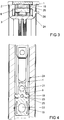
- FIG. 3 shows a cross section of the fitting part 1 from FIG. 1 after installation in a fitting groove 24 of a window in the region of the second projection 19 of the holding element 6. It can be seen that the second projection 19 is resiliently supported on side walls 25 of the fitting groove 24 in the region of a groove projection 26. The groove projection 26 is not engaged behind by the retaining element 6.
- FIG. 4 shows a longitudinal section through the fitting part 1 FIG. 1 after mounting in the fitting groove 24 of the window. It can be seen that the first projection 18 is pressed into the side walls 25 of the fitting groove 24 and a longitudinal movement of the fitting part 1 in the fitting groove 24 prevented. Furthermore, in the longitudinal section perpendicular to the plane arranged SSausappel 21, 22 and the Nietaus Principleung 23 can be seen.
Landscapes
- Engineering & Computer Science (AREA)
- Mechanical Engineering (AREA)
- Connection Of Plates (AREA)
- Clamps And Clips (AREA)
- Installation Of Indoor Wiring (AREA)
- Vehicle Step Arrangements And Article Storage (AREA)
Claims (11)
- Elément de retenue (6) d'une partie de ferrure (1) d'une ferrure à tringle dans une rainure de ferrure (24) d'une fenêtre avec des saillies (18, 19) tournées, dans l'état monté, vers des parois latérales (25) de la rainure de ferrure (24), avec respectivement une surface d'appui (14 - 16) destinée à supporter un rail de recouvrement (2) et une tringle (3) de la partie de ferrure (1), une première saillie (18) étant, dans l'état monté, disposée transversalement à la direction longitudinale de la tringle (3), et étant constituée de façon non élastique pour l'insertion dans la paroi latérale (25) de la rainure de ferrure (24), et une deuxième saillie (19), disposée près de la première saillie (18), étant constituée avec une élasticité de ressort, caractérisé en ce que, dans l'état monté, la deuxième saillie (19) a un profilage (27) disposé le long de la direction longitudinale de la tringle (3).
- Elément de retenue selon la revendication 1, caractérisé en ce que la deuxième saillie (19) a la forme d'un arc fermé.
- Elément de retenue selon l'une des revendications précédentes, caractérisé en ce que les surfaces d'appui (14 - 16) du rail de recouvrement (2) et de la tringle (3) sont disposées sur des côtés éloignés l'un de l'autre d'une entretoise (13).
- Elément de retenue selon la revendication 3, caractérisé en ce que l'entretoise (13) à la hauteur d'un boîtier (5) pour un paquet de ressorts (4) d'un renvoi d'angle.
- Elément de retenue selon l'une des revendications précédentes, caractérisé en ce que la première saillie (18) a une arête (20) en saillie disposée perpendiculairement aux surfaces d'appui (14 - 16).
- Elément de retenue selon l'une des revendications 3 à 5, caractérisé en ce que la première saillie (18) et la deuxième saillie (19) sont réalisées d'un seul tenant avec l'entretoise (13).
- Elément de retenue selon l'une des revendications 3 à 6, caractérisé en ce qu'une base (12) a des surfaces de guidage (17) latérales pour un trou oblong (9) de la tringle (3), et en ce que deux entretoises (13) dépassent diamétralement de la base (12).
- Elément de retenue selon l'une des revendications précédentes, caractérisé en ce qu'un creux pour rivet (23) ou un rivet destiné au raccordement au rail de recouvrement (2) est disposé sur la surface d'appui (14) du rail de recouvrement (2).
- Elément de retenue selon la revendication 7 ou 8, caractérisé en ce que la base (12) a des crochets d'encliquetage (8) destinés à agripper par l'arrière la tringle (3).
- Elément de retenue selon l'une des revendications précédentes, caractérisé par une constitution de l'élément de retenue (6) avec une section transversale en forme de T.
- Elément de retenue selon l'une des revendications précédentes, caractérisé en ce qu'il est prévu deux creux pour vis (21, 22) pour le passage de respectivement une vis de fixation pour respectivement un tronçon du rail de recouvrement (2), et en ce que des surfaces d'appui (14 - 15) adjacentes l'une à l'autre sont disposées à la même hauteur pour le support de respectivement une extrémité d'un rail de recouvrement (2).
Priority Applications (1)
| Application Number | Priority Date | Filing Date | Title |
|---|---|---|---|
| PL11183999T PL2444573T3 (pl) | 2010-10-19 | 2011-10-05 | Element mocujący części okucia zasuwnicowego |
Applications Claiming Priority (1)
| Application Number | Priority Date | Filing Date | Title |
|---|---|---|---|
| DE102010042628A DE102010042628A1 (de) | 2010-10-19 | 2010-10-19 | Halteelement eines Beschlagteils eines Treibstangenbeschlages |
Publications (3)
| Publication Number | Publication Date |
|---|---|
| EP2444573A2 EP2444573A2 (fr) | 2012-04-25 |
| EP2444573A3 EP2444573A3 (fr) | 2016-12-28 |
| EP2444573B1 true EP2444573B1 (fr) | 2019-07-24 |
Family
ID=44719728
Family Applications (1)
| Application Number | Title | Priority Date | Filing Date |
|---|---|---|---|
| EP11183999.9A Active EP2444573B1 (fr) | 2010-10-19 | 2011-10-05 | Elément de retenue d'une garniture de ferrure à tringle |
Country Status (4)
| Country | Link |
|---|---|
| EP (1) | EP2444573B1 (fr) |
| DE (1) | DE102010042628A1 (fr) |
| ES (1) | ES2747757T3 (fr) |
| PL (1) | PL2444573T3 (fr) |
Family Cites Families (3)
| Publication number | Priority date | Publication date | Assignee | Title |
|---|---|---|---|---|
| DE2407196C3 (de) * | 1974-02-15 | 1985-11-14 | August Bilstein GmbH & Co KG, 5828 Ennepetal | Treibstangenbeschlag für insbesondere aus Kunststoff oder Holz bestehende Fenster, Türen od.dgl. |
| DE19646988C5 (de) | 1996-11-14 | 2014-07-03 | Roto Frank Ag | Beschlag für ein Fenster |
| DE102008062303A1 (de) | 2008-12-15 | 2010-06-17 | Aug. Winkhaus Gmbh & Co. Kg | Beschlagbaugruppe für ein Treibstangenbeschlagsystem |
-
2010
- 2010-10-19 DE DE102010042628A patent/DE102010042628A1/de not_active Withdrawn
-
2011
- 2011-10-05 EP EP11183999.9A patent/EP2444573B1/fr active Active
- 2011-10-05 PL PL11183999T patent/PL2444573T3/pl unknown
- 2011-10-05 ES ES11183999T patent/ES2747757T3/es active Active
Non-Patent Citations (1)
| Title |
|---|
| None * |
Also Published As
| Publication number | Publication date |
|---|---|
| DE102010042628A1 (de) | 2012-04-19 |
| PL2444573T3 (pl) | 2019-12-31 |
| EP2444573A3 (fr) | 2016-12-28 |
| ES2747757T3 (es) | 2020-03-11 |
| EP2444573A2 (fr) | 2012-04-25 |
Similar Documents
| Publication | Publication Date | Title |
|---|---|---|
| DE19646988C5 (de) | Beschlag für ein Fenster | |
| DE202007003060U1 (de) | Verbindungselement | |
| EP1865135B1 (fr) | Guide pour ferrure de porte coulissante | |
| EP2444574B1 (fr) | Elément de retenue d'une garniture de ferrure à tringle | |
| DE19730600A1 (de) | Stulpschienenbeschlag | |
| EP0843064B1 (fr) | Ferrure pour un fenêtre | |
| EP2754805B1 (fr) | Tringle de verrouillage pour une crémone | |
| EP0937847A1 (fr) | Têtière à fixer dans une gorge de ferrure, notamment pour recouvrir une tringle de manoeuvre de porte, fenêtre ou similaire en au moins une partie | |
| EP1234985B1 (fr) | Système de liaison par serrage | |
| EP2754803B1 (fr) | Crémone de fenêtre ou de porte et tringle pour une telle crémone | |
| EP2444573B1 (fr) | Elément de retenue d'une garniture de ferrure à tringle | |
| EP2592283B1 (fr) | Connecteur pour meuble | |
| DE102011000373B4 (de) | Laufschienensystem und Verfahren zum Herstellen einer mehrläufigen Laufschiene | |
| EP1229282B1 (fr) | Adaptateur pour le montage de collier de fixation | |
| EP2132391B1 (fr) | Ensemble tringle de crémone constitué d'au moins une tringle et d'au moins un élément de guidage de tringle | |
| EP2620579B1 (fr) | Elément de liaison destiné à la liaison de pièces profilées | |
| EP3067495B1 (fr) | Élement de retenue d'une partie de ferrure de tringle | |
| EP2199509B1 (fr) | Bloc d'armature pour un système d'armature de tige motrice | |
| EP2754802A2 (fr) | Crémone de fenêtre ou de porte | |
| WO2008068304A2 (fr) | Crémone | |
| EP1862622B1 (fr) | Pièce d'assemblage d'angle pour un ensemble de manoeuvre-têtière, pour fenêtres, portes ou similaires | |
| EP3441547A1 (fr) | Gâche pour une ferrure à tige d'entraînement | |
| EP3760818B1 (fr) | Gâche pour une ferrure à crémone | |
| EP0628694A1 (fr) | Assemblage d'angle ou entre croisillons de profilés de cadre | |
| DE202007016892U1 (de) | Verbindungssystem für rinnenförmige Profilstäbe und Verbindungsanordnung |
Legal Events
| Date | Code | Title | Description |
|---|---|---|---|
| AK | Designated contracting states |
Kind code of ref document: A2 Designated state(s): AL AT BE BG CH CY CZ DE DK EE ES FI FR GB GR HR HU IE IS IT LI LT LU LV MC MK MT NL NO PL PT RO RS SE SI SK SM TR |
|
| AX | Request for extension of the european patent |
Extension state: BA ME |
|
| PUAI | Public reference made under article 153(3) epc to a published international application that has entered the european phase |
Free format text: ORIGINAL CODE: 0009012 |
|
| PUAL | Search report despatched |
Free format text: ORIGINAL CODE: 0009013 |
|
| AK | Designated contracting states |
Kind code of ref document: A3 Designated state(s): AL AT BE BG CH CY CZ DE DK EE ES FI FR GB GR HR HU IE IS IT LI LT LU LV MC MK MT NL NO PL PT RO RS SE SI SK SM TR |
|
| AX | Request for extension of the european patent |
Extension state: BA ME |
|
| RIC1 | Information provided on ipc code assigned before grant |
Ipc: E05C 9/24 20060101ALI20161124BHEP Ipc: E05C 9/22 20060101AFI20161124BHEP |
|
| STAA | Information on the status of an ep patent application or granted ep patent |
Free format text: STATUS: REQUEST FOR EXAMINATION WAS MADE |
|
| 17P | Request for examination filed |
Effective date: 20170531 |
|
| RBV | Designated contracting states (corrected) |
Designated state(s): AL AT BE BG CH CY CZ DE DK EE ES FI FR GB GR HR HU IE IS IT LI LT LU LV MC MK MT NL NO PL PT RO RS SE SI SK SM TR |
|
| GRAP | Despatch of communication of intention to grant a patent |
Free format text: ORIGINAL CODE: EPIDOSNIGR1 |
|
| RIC1 | Information provided on ipc code assigned before grant |
Ipc: E05F 7/08 20060101ALI20190201BHEP Ipc: E05C 9/24 20060101ALI20190201BHEP Ipc: E05C 9/22 20060101AFI20190201BHEP |
|
| STAA | Information on the status of an ep patent application or granted ep patent |
Free format text: STATUS: GRANT OF PATENT IS INTENDED |
|
| INTG | Intention to grant announced |
Effective date: 20190314 |
|
| GRAS | Grant fee paid |
Free format text: ORIGINAL CODE: EPIDOSNIGR3 |
|
| GRAA | (expected) grant |
Free format text: ORIGINAL CODE: 0009210 |
|
| STAA | Information on the status of an ep patent application or granted ep patent |
Free format text: STATUS: THE PATENT HAS BEEN GRANTED |
|
| AK | Designated contracting states |
Kind code of ref document: B1 Designated state(s): AL AT BE BG CH CY CZ DE DK EE ES FI FR GB GR HR HU IE IS IT LI LT LU LV MC MK MT NL NO PL PT RO RS SE SI SK SM TR |
|
| REG | Reference to a national code |
Ref country code: GB Ref legal event code: FG4D Free format text: NOT ENGLISH |
|
| REG | Reference to a national code |
Ref country code: CH Ref legal event code: EP |
|
| REG | Reference to a national code |
Ref country code: DE Ref legal event code: R096 Ref document number: 502011015926 Country of ref document: DE |
|
| REG | Reference to a national code |
Ref country code: AT Ref legal event code: REF Ref document number: 1158382 Country of ref document: AT Kind code of ref document: T Effective date: 20190815 |
|
| REG | Reference to a national code |
Ref country code: IE Ref legal event code: FG4D Free format text: LANGUAGE OF EP DOCUMENT: GERMAN |
|
| REG | Reference to a national code |
Ref country code: NL Ref legal event code: MP Effective date: 20190724 |
|
| REG | Reference to a national code |
Ref country code: LT Ref legal event code: MG4D |
|
| PG25 | Lapsed in a contracting state [announced via postgrant information from national office to epo] |
Ref country code: HR Free format text: LAPSE BECAUSE OF FAILURE TO SUBMIT A TRANSLATION OF THE DESCRIPTION OR TO PAY THE FEE WITHIN THE PRESCRIBED TIME-LIMIT Effective date: 20190724 Ref country code: SE Free format text: LAPSE BECAUSE OF FAILURE TO SUBMIT A TRANSLATION OF THE DESCRIPTION OR TO PAY THE FEE WITHIN THE PRESCRIBED TIME-LIMIT Effective date: 20190724 Ref country code: BG Free format text: LAPSE BECAUSE OF FAILURE TO SUBMIT A TRANSLATION OF THE DESCRIPTION OR TO PAY THE FEE WITHIN THE PRESCRIBED TIME-LIMIT Effective date: 20191024 Ref country code: LT Free format text: LAPSE BECAUSE OF FAILURE TO SUBMIT A TRANSLATION OF THE DESCRIPTION OR TO PAY THE FEE WITHIN THE PRESCRIBED TIME-LIMIT Effective date: 20190724 Ref country code: PT Free format text: LAPSE BECAUSE OF FAILURE TO SUBMIT A TRANSLATION OF THE DESCRIPTION OR TO PAY THE FEE WITHIN THE PRESCRIBED TIME-LIMIT Effective date: 20191125 Ref country code: NL Free format text: LAPSE BECAUSE OF FAILURE TO SUBMIT A TRANSLATION OF THE DESCRIPTION OR TO PAY THE FEE WITHIN THE PRESCRIBED TIME-LIMIT Effective date: 20190724 Ref country code: FI Free format text: LAPSE BECAUSE OF FAILURE TO SUBMIT A TRANSLATION OF THE DESCRIPTION OR TO PAY THE FEE WITHIN THE PRESCRIBED TIME-LIMIT Effective date: 20190724 Ref country code: NO Free format text: LAPSE BECAUSE OF FAILURE TO SUBMIT A TRANSLATION OF THE DESCRIPTION OR TO PAY THE FEE WITHIN THE PRESCRIBED TIME-LIMIT Effective date: 20191024 |
|
| PG25 | Lapsed in a contracting state [announced via postgrant information from national office to epo] |
Ref country code: IS Free format text: LAPSE BECAUSE OF FAILURE TO SUBMIT A TRANSLATION OF THE DESCRIPTION OR TO PAY THE FEE WITHIN THE PRESCRIBED TIME-LIMIT Effective date: 20191124 Ref country code: LV Free format text: LAPSE BECAUSE OF FAILURE TO SUBMIT A TRANSLATION OF THE DESCRIPTION OR TO PAY THE FEE WITHIN THE PRESCRIBED TIME-LIMIT Effective date: 20190724 Ref country code: AL Free format text: LAPSE BECAUSE OF FAILURE TO SUBMIT A TRANSLATION OF THE DESCRIPTION OR TO PAY THE FEE WITHIN THE PRESCRIBED TIME-LIMIT Effective date: 20190724 Ref country code: GR Free format text: LAPSE BECAUSE OF FAILURE TO SUBMIT A TRANSLATION OF THE DESCRIPTION OR TO PAY THE FEE WITHIN THE PRESCRIBED TIME-LIMIT Effective date: 20191025 Ref country code: RS Free format text: LAPSE BECAUSE OF FAILURE TO SUBMIT A TRANSLATION OF THE DESCRIPTION OR TO PAY THE FEE WITHIN THE PRESCRIBED TIME-LIMIT Effective date: 20190724 |
|
| PGFP | Annual fee paid to national office [announced via postgrant information from national office to epo] |
Ref country code: ES Payment date: 20191125 Year of fee payment: 9 |
|
| REG | Reference to a national code |
Ref country code: ES Ref legal event code: FG2A Ref document number: 2747757 Country of ref document: ES Kind code of ref document: T3 Effective date: 20200311 |
|
| PG25 | Lapsed in a contracting state [announced via postgrant information from national office to epo] |
Ref country code: IT Free format text: LAPSE BECAUSE OF FAILURE TO SUBMIT A TRANSLATION OF THE DESCRIPTION OR TO PAY THE FEE WITHIN THE PRESCRIBED TIME-LIMIT Effective date: 20190724 Ref country code: EE Free format text: LAPSE BECAUSE OF FAILURE TO SUBMIT A TRANSLATION OF THE DESCRIPTION OR TO PAY THE FEE WITHIN THE PRESCRIBED TIME-LIMIT Effective date: 20190724 Ref country code: RO Free format text: LAPSE BECAUSE OF FAILURE TO SUBMIT A TRANSLATION OF THE DESCRIPTION OR TO PAY THE FEE WITHIN THE PRESCRIBED TIME-LIMIT Effective date: 20190724 Ref country code: DK Free format text: LAPSE BECAUSE OF FAILURE TO SUBMIT A TRANSLATION OF THE DESCRIPTION OR TO PAY THE FEE WITHIN THE PRESCRIBED TIME-LIMIT Effective date: 20190724 |
|
| PGFP | Annual fee paid to national office [announced via postgrant information from national office to epo] |
Ref country code: GB Payment date: 20191029 Year of fee payment: 9 |
|
| PG25 | Lapsed in a contracting state [announced via postgrant information from national office to epo] |
Ref country code: CZ Free format text: LAPSE BECAUSE OF FAILURE TO SUBMIT A TRANSLATION OF THE DESCRIPTION OR TO PAY THE FEE WITHIN THE PRESCRIBED TIME-LIMIT Effective date: 20190724 Ref country code: SK Free format text: LAPSE BECAUSE OF FAILURE TO SUBMIT A TRANSLATION OF THE DESCRIPTION OR TO PAY THE FEE WITHIN THE PRESCRIBED TIME-LIMIT Effective date: 20190724 Ref country code: MC Free format text: LAPSE BECAUSE OF FAILURE TO SUBMIT A TRANSLATION OF THE DESCRIPTION OR TO PAY THE FEE WITHIN THE PRESCRIBED TIME-LIMIT Effective date: 20190724 Ref country code: IS Free format text: LAPSE BECAUSE OF FAILURE TO SUBMIT A TRANSLATION OF THE DESCRIPTION OR TO PAY THE FEE WITHIN THE PRESCRIBED TIME-LIMIT Effective date: 20200224 Ref country code: SM Free format text: LAPSE BECAUSE OF FAILURE TO SUBMIT A TRANSLATION OF THE DESCRIPTION OR TO PAY THE FEE WITHIN THE PRESCRIBED TIME-LIMIT Effective date: 20190724 |
|
| REG | Reference to a national code |
Ref country code: CH Ref legal event code: PL |
|
| REG | Reference to a national code |
Ref country code: DE Ref legal event code: R097 Ref document number: 502011015926 Country of ref document: DE |
|
| PLBE | No opposition filed within time limit |
Free format text: ORIGINAL CODE: 0009261 |
|
| STAA | Information on the status of an ep patent application or granted ep patent |
Free format text: STATUS: NO OPPOSITION FILED WITHIN TIME LIMIT |
|
| PG2D | Information on lapse in contracting state deleted |
Ref country code: IS |
|
| PG25 | Lapsed in a contracting state [announced via postgrant information from national office to epo] |
Ref country code: LU Free format text: LAPSE BECAUSE OF NON-PAYMENT OF DUE FEES Effective date: 20191005 Ref country code: CH Free format text: LAPSE BECAUSE OF NON-PAYMENT OF DUE FEES Effective date: 20191031 Ref country code: LI Free format text: LAPSE BECAUSE OF NON-PAYMENT OF DUE FEES Effective date: 20191031 |
|
| 26N | No opposition filed |
Effective date: 20200603 |
|
| REG | Reference to a national code |
Ref country code: BE Ref legal event code: MM Effective date: 20191031 |
|
| PG25 | Lapsed in a contracting state [announced via postgrant information from national office to epo] |
Ref country code: BE Free format text: LAPSE BECAUSE OF NON-PAYMENT OF DUE FEES Effective date: 20191031 Ref country code: SI Free format text: LAPSE BECAUSE OF FAILURE TO SUBMIT A TRANSLATION OF THE DESCRIPTION OR TO PAY THE FEE WITHIN THE PRESCRIBED TIME-LIMIT Effective date: 20190724 |
|
| PG25 | Lapsed in a contracting state [announced via postgrant information from national office to epo] |
Ref country code: IE Free format text: LAPSE BECAUSE OF NON-PAYMENT OF DUE FEES Effective date: 20191005 |
|
| PG25 | Lapsed in a contracting state [announced via postgrant information from national office to epo] |
Ref country code: CY Free format text: LAPSE BECAUSE OF FAILURE TO SUBMIT A TRANSLATION OF THE DESCRIPTION OR TO PAY THE FEE WITHIN THE PRESCRIBED TIME-LIMIT Effective date: 20190724 |
|
| GBPC | Gb: european patent ceased through non-payment of renewal fee |
Effective date: 20201005 |
|
| PG25 | Lapsed in a contracting state [announced via postgrant information from national office to epo] |
Ref country code: MT Free format text: LAPSE BECAUSE OF FAILURE TO SUBMIT A TRANSLATION OF THE DESCRIPTION OR TO PAY THE FEE WITHIN THE PRESCRIBED TIME-LIMIT Effective date: 20190724 Ref country code: HU Free format text: LAPSE BECAUSE OF FAILURE TO SUBMIT A TRANSLATION OF THE DESCRIPTION OR TO PAY THE FEE WITHIN THE PRESCRIBED TIME-LIMIT; INVALID AB INITIO Effective date: 20111005 |
|
| PG25 | Lapsed in a contracting state [announced via postgrant information from national office to epo] |
Ref country code: GB Free format text: LAPSE BECAUSE OF NON-PAYMENT OF DUE FEES Effective date: 20201005 |
|
| PGFP | Annual fee paid to national office [announced via postgrant information from national office to epo] |
Ref country code: TR Payment date: 20210929 Year of fee payment: 11 |
|
| REG | Reference to a national code |
Ref country code: ES Ref legal event code: FD2A Effective date: 20220121 |
|
| PG25 | Lapsed in a contracting state [announced via postgrant information from national office to epo] |
Ref country code: ES Free format text: LAPSE BECAUSE OF NON-PAYMENT OF DUE FEES Effective date: 20201006 |
|
| PG25 | Lapsed in a contracting state [announced via postgrant information from national office to epo] |
Ref country code: MK Free format text: LAPSE BECAUSE OF FAILURE TO SUBMIT A TRANSLATION OF THE DESCRIPTION OR TO PAY THE FEE WITHIN THE PRESCRIBED TIME-LIMIT Effective date: 20190724 |
|
| P01 | Opt-out of the competence of the unified patent court (upc) registered |
Effective date: 20230515 |
|
| PGFP | Annual fee paid to national office [announced via postgrant information from national office to epo] |
Ref country code: PL Payment date: 20230922 Year of fee payment: 13 |
|
| PGFP | Annual fee paid to national office [announced via postgrant information from national office to epo] |
Ref country code: FR Payment date: 20231023 Year of fee payment: 13 Ref country code: DE Payment date: 20231018 Year of fee payment: 13 Ref country code: AT Payment date: 20231019 Year of fee payment: 13 |