EP2444314A1 - Electricity generating device of lng carrier and method thereof - Google Patents
Electricity generating device of lng carrier and method thereof Download PDFInfo
- Publication number
- EP2444314A1 EP2444314A1 EP10851076A EP10851076A EP2444314A1 EP 2444314 A1 EP2444314 A1 EP 2444314A1 EP 10851076 A EP10851076 A EP 10851076A EP 10851076 A EP10851076 A EP 10851076A EP 2444314 A1 EP2444314 A1 EP 2444314A1
- Authority
- EP
- European Patent Office
- Prior art keywords
- fuel cell
- gas
- electricity
- steam
- carbon dioxide
- Prior art date
- Legal status (The legal status is an assumption and is not a legal conclusion. Google has not performed a legal analysis and makes no representation as to the accuracy of the status listed.)
- Ceased
Links
- 230000005611 electricity Effects 0.000 title claims abstract description 123
- 238000000034 method Methods 0.000 title claims description 28
- 239000000446 fuel Substances 0.000 claims abstract description 256
- 239000007789 gas Substances 0.000 claims abstract description 149
- 239000003949 liquefied natural gas Substances 0.000 claims abstract description 115
- VNWKTOKETHGBQD-UHFFFAOYSA-N methane Chemical compound C VNWKTOKETHGBQD-UHFFFAOYSA-N 0.000 claims abstract description 22
- 238000003487 electrochemical reaction Methods 0.000 claims abstract description 17
- 238000002407 reforming Methods 0.000 claims abstract description 15
- 239000003345 natural gas Substances 0.000 claims abstract description 10
- CURLTUGMZLYLDI-UHFFFAOYSA-N Carbon dioxide Chemical compound O=C=O CURLTUGMZLYLDI-UHFFFAOYSA-N 0.000 claims description 150
- 229910002092 carbon dioxide Inorganic materials 0.000 claims description 81
- 239000001569 carbon dioxide Substances 0.000 claims description 81
- 229910002091 carbon monoxide Inorganic materials 0.000 claims description 38
- UGFAIRIUMAVXCW-UHFFFAOYSA-N Carbon monoxide Chemical compound [O+]#[C-] UGFAIRIUMAVXCW-UHFFFAOYSA-N 0.000 claims description 34
- 230000009977 dual effect Effects 0.000 claims description 28
- XLYOFNOQVPJJNP-UHFFFAOYSA-N water Substances O XLYOFNOQVPJJNP-UHFFFAOYSA-N 0.000 claims description 28
- 239000001257 hydrogen Substances 0.000 claims description 27
- 229910052739 hydrogen Inorganic materials 0.000 claims description 27
- 239000002918 waste heat Substances 0.000 claims description 23
- UFHFLCQGNIYNRP-UHFFFAOYSA-N Hydrogen Chemical compound [H][H] UFHFLCQGNIYNRP-UHFFFAOYSA-N 0.000 claims description 22
- 238000011084 recovery Methods 0.000 claims description 19
- 239000012528 membrane Substances 0.000 claims description 6
- 238000002347 injection Methods 0.000 claims description 4
- 239000007924 injection Substances 0.000 claims description 4
- BVKZGUZCCUSVTD-UHFFFAOYSA-L Carbonate Chemical compound [O-]C([O-])=O BVKZGUZCCUSVTD-UHFFFAOYSA-L 0.000 claims description 3
- 239000005518 polymer electrolyte Substances 0.000 claims description 3
- 239000007787 solid Substances 0.000 claims description 3
- 238000000629 steam reforming Methods 0.000 claims description 3
- 238000006243 chemical reaction Methods 0.000 description 13
- RWSOTUBLDIXVET-UHFFFAOYSA-N Dihydrogen sulfide Chemical compound S RWSOTUBLDIXVET-UHFFFAOYSA-N 0.000 description 6
- QAOWNCQODCNURD-UHFFFAOYSA-N Sulfuric acid Chemical compound OS(O)(=O)=O QAOWNCQODCNURD-UHFFFAOYSA-N 0.000 description 6
- 238000010586 diagram Methods 0.000 description 6
- 150000002431 hydrogen Chemical class 0.000 description 5
- PXHVJJICTQNCMI-UHFFFAOYSA-N Nickel Chemical compound [Ni] PXHVJJICTQNCMI-UHFFFAOYSA-N 0.000 description 3
- 239000000463 material Substances 0.000 description 3
- 238000007254 oxidation reaction Methods 0.000 description 3
- 239000001117 sulphuric acid Substances 0.000 description 3
- 235000011149 sulphuric acid Nutrition 0.000 description 3
- 239000002912 waste gas Substances 0.000 description 3
- NINIDFKCEFEMDL-UHFFFAOYSA-N Sulfur Chemical compound [S] NINIDFKCEFEMDL-UHFFFAOYSA-N 0.000 description 2
- QVGXLLKOCUKJST-UHFFFAOYSA-N atomic oxygen Chemical compound [O] QVGXLLKOCUKJST-UHFFFAOYSA-N 0.000 description 2
- 238000002485 combustion reaction Methods 0.000 description 2
- 238000010276 construction Methods 0.000 description 2
- 238000003912 environmental pollution Methods 0.000 description 2
- 229910000037 hydrogen sulfide Inorganic materials 0.000 description 2
- 230000003647 oxidation Effects 0.000 description 2
- 229910052760 oxygen Inorganic materials 0.000 description 2
- 239000001301 oxygen Substances 0.000 description 2
- 229910052717 sulfur Inorganic materials 0.000 description 2
- 239000011593 sulfur Substances 0.000 description 2
- OKTJSMMVPCPJKN-UHFFFAOYSA-N Carbon Chemical compound [C] OKTJSMMVPCPJKN-UHFFFAOYSA-N 0.000 description 1
- DPFFXSPEODLYOH-UHFFFAOYSA-N bis($l^{1}-oxidanyl)methanone Chemical compound [O]C([O])=O DPFFXSPEODLYOH-UHFFFAOYSA-N 0.000 description 1
- 229910052799 carbon Inorganic materials 0.000 description 1
- 239000003054 catalyst Substances 0.000 description 1
- 230000000694 effects Effects 0.000 description 1
- 230000008020 evaporation Effects 0.000 description 1
- 238000001704 evaporation Methods 0.000 description 1
- -1 for example Substances 0.000 description 1
- 239000007788 liquid Substances 0.000 description 1
- 238000012986 modification Methods 0.000 description 1
- 230000004048 modification Effects 0.000 description 1
- 229910052759 nickel Inorganic materials 0.000 description 1
- 239000000243 solution Substances 0.000 description 1
- LPSWFOCTMJQJIS-UHFFFAOYSA-N sulfanium;hydroxide Chemical compound [OH-].[SH3+] LPSWFOCTMJQJIS-UHFFFAOYSA-N 0.000 description 1
Images


Classifications
-
- B—PERFORMING OPERATIONS; TRANSPORTING
- B63—SHIPS OR OTHER WATERBORNE VESSELS; RELATED EQUIPMENT
- B63J—AUXILIARIES ON VESSELS
- B63J3/00—Driving of auxiliaries
- B63J3/04—Driving of auxiliaries from power plant other than propulsion power plant
-
- B—PERFORMING OPERATIONS; TRANSPORTING
- B63—SHIPS OR OTHER WATERBORNE VESSELS; RELATED EQUIPMENT
- B63B—SHIPS OR OTHER WATERBORNE VESSELS; EQUIPMENT FOR SHIPPING
- B63B25/00—Load-accommodating arrangements, e.g. stowing, trimming; Vessels characterised thereby
- B63B25/02—Load-accommodating arrangements, e.g. stowing, trimming; Vessels characterised thereby for bulk goods
- B63B25/08—Load-accommodating arrangements, e.g. stowing, trimming; Vessels characterised thereby for bulk goods fluid
- B63B25/12—Load-accommodating arrangements, e.g. stowing, trimming; Vessels characterised thereby for bulk goods fluid closed
- B63B25/14—Load-accommodating arrangements, e.g. stowing, trimming; Vessels characterised thereby for bulk goods fluid closed pressurised
-
- B—PERFORMING OPERATIONS; TRANSPORTING
- B63—SHIPS OR OTHER WATERBORNE VESSELS; RELATED EQUIPMENT
- B63H—MARINE PROPULSION OR STEERING
- B63H21/00—Use of propulsion power plant or units on vessels
- B63H21/12—Use of propulsion power plant or units on vessels the vessels being motor-driven
- B63H21/17—Use of propulsion power plant or units on vessels the vessels being motor-driven by electric motor
-
- C—CHEMISTRY; METALLURGY
- C01—INORGANIC CHEMISTRY
- C01B—NON-METALLIC ELEMENTS; COMPOUNDS THEREOF; METALLOIDS OR COMPOUNDS THEREOF NOT COVERED BY SUBCLASS C01C
- C01B3/00—Hydrogen; Gaseous mixtures containing hydrogen; Separation of hydrogen from mixtures containing it; Purification of hydrogen
- C01B3/02—Production of hydrogen or of gaseous mixtures containing a substantial proportion of hydrogen
- C01B3/32—Production of hydrogen or of gaseous mixtures containing a substantial proportion of hydrogen by reaction of gaseous or liquid organic compounds with gasifying agents, e.g. water, carbon dioxide, air
- C01B3/34—Production of hydrogen or of gaseous mixtures containing a substantial proportion of hydrogen by reaction of gaseous or liquid organic compounds with gasifying agents, e.g. water, carbon dioxide, air by reaction of hydrocarbons with gasifying agents
-
- H—ELECTRICITY
- H01—ELECTRIC ELEMENTS
- H01M—PROCESSES OR MEANS, e.g. BATTERIES, FOR THE DIRECT CONVERSION OF CHEMICAL ENERGY INTO ELECTRICAL ENERGY
- H01M16/00—Structural combinations of different types of electrochemical generators
- H01M16/003—Structural combinations of different types of electrochemical generators of fuel cells with other electrochemical devices, e.g. capacitors, electrolysers
-
- H—ELECTRICITY
- H01—ELECTRIC ELEMENTS
- H01M—PROCESSES OR MEANS, e.g. BATTERIES, FOR THE DIRECT CONVERSION OF CHEMICAL ENERGY INTO ELECTRICAL ENERGY
- H01M8/00—Fuel cells; Manufacture thereof
- H01M8/06—Combination of fuel cells with means for production of reactants or for treatment of residues
- H01M8/0606—Combination of fuel cells with means for production of reactants or for treatment of residues with means for production of gaseous reactants
- H01M8/0612—Combination of fuel cells with means for production of reactants or for treatment of residues with means for production of gaseous reactants from carbon-containing material
- H01M8/0618—Reforming processes, e.g. autothermal, partial oxidation or steam reforming
-
- H—ELECTRICITY
- H01—ELECTRIC ELEMENTS
- H01M—PROCESSES OR MEANS, e.g. BATTERIES, FOR THE DIRECT CONVERSION OF CHEMICAL ENERGY INTO ELECTRICAL ENERGY
- H01M8/00—Fuel cells; Manufacture thereof
- H01M8/06—Combination of fuel cells with means for production of reactants or for treatment of residues
- H01M8/0662—Treatment of gaseous reactants or gaseous residues, e.g. cleaning
- H01M8/0668—Removal of carbon monoxide or carbon dioxide
-
- B—PERFORMING OPERATIONS; TRANSPORTING
- B63—SHIPS OR OTHER WATERBORNE VESSELS; RELATED EQUIPMENT
- B63H—MARINE PROPULSION OR STEERING
- B63H21/00—Use of propulsion power plant or units on vessels
- B63H2021/003—Use of propulsion power plant or units on vessels the power plant using fuel cells for energy supply or accumulation, e.g. for buffering photovoltaic energy
-
- B—PERFORMING OPERATIONS; TRANSPORTING
- B63—SHIPS OR OTHER WATERBORNE VESSELS; RELATED EQUIPMENT
- B63J—AUXILIARIES ON VESSELS
- B63J99/00—Subject matter not provided for in other groups of this subclass
- B63J2099/001—Burning of transported goods, e.g. fuel, boil-off or refuse
- B63J2099/003—Burning of transported goods, e.g. fuel, boil-off or refuse of cargo oil or fuel, or of boil-off gases, e.g. for propulsive purposes
-
- C—CHEMISTRY; METALLURGY
- C01—INORGANIC CHEMISTRY
- C01B—NON-METALLIC ELEMENTS; COMPOUNDS THEREOF; METALLOIDS OR COMPOUNDS THEREOF NOT COVERED BY SUBCLASS C01C
- C01B2203/00—Integrated processes for the production of hydrogen or synthesis gas
- C01B2203/02—Processes for making hydrogen or synthesis gas
- C01B2203/0205—Processes for making hydrogen or synthesis gas containing a reforming step
-
- C—CHEMISTRY; METALLURGY
- C01—INORGANIC CHEMISTRY
- C01B—NON-METALLIC ELEMENTS; COMPOUNDS THEREOF; METALLOIDS OR COMPOUNDS THEREOF NOT COVERED BY SUBCLASS C01C
- C01B2203/00—Integrated processes for the production of hydrogen or synthesis gas
- C01B2203/06—Integration with other chemical processes
- C01B2203/066—Integration with other chemical processes with fuel cells
-
- C—CHEMISTRY; METALLURGY
- C01—INORGANIC CHEMISTRY
- C01B—NON-METALLIC ELEMENTS; COMPOUNDS THEREOF; METALLOIDS OR COMPOUNDS THEREOF NOT COVERED BY SUBCLASS C01C
- C01B2203/00—Integrated processes for the production of hydrogen or synthesis gas
- C01B2203/12—Feeding the process for making hydrogen or synthesis gas
- C01B2203/1205—Composition of the feed
- C01B2203/1211—Organic compounds or organic mixtures used in the process for making hydrogen or synthesis gas
- C01B2203/1235—Hydrocarbons
- C01B2203/1241—Natural gas or methane
-
- C—CHEMISTRY; METALLURGY
- C01—INORGANIC CHEMISTRY
- C01B—NON-METALLIC ELEMENTS; COMPOUNDS THEREOF; METALLOIDS OR COMPOUNDS THEREOF NOT COVERED BY SUBCLASS C01C
- C01B2203/00—Integrated processes for the production of hydrogen or synthesis gas
- C01B2203/12—Feeding the process for making hydrogen or synthesis gas
- C01B2203/1288—Evaporation of one or more of the different feed components
-
- H—ELECTRICITY
- H01—ELECTRIC ELEMENTS
- H01M—PROCESSES OR MEANS, e.g. BATTERIES, FOR THE DIRECT CONVERSION OF CHEMICAL ENERGY INTO ELECTRICAL ENERGY
- H01M8/00—Fuel cells; Manufacture thereof
- H01M8/10—Fuel cells with solid electrolytes
- H01M2008/1095—Fuel cells with polymeric electrolytes
-
- H—ELECTRICITY
- H01—ELECTRIC ELEMENTS
- H01M—PROCESSES OR MEANS, e.g. BATTERIES, FOR THE DIRECT CONVERSION OF CHEMICAL ENERGY INTO ELECTRICAL ENERGY
- H01M8/00—Fuel cells; Manufacture thereof
- H01M8/10—Fuel cells with solid electrolytes
- H01M8/12—Fuel cells with solid electrolytes operating at high temperature, e.g. with stabilised ZrO2 electrolyte
- H01M2008/1293—Fuel cells with solid oxide electrolytes
-
- H—ELECTRICITY
- H01—ELECTRIC ELEMENTS
- H01M—PROCESSES OR MEANS, e.g. BATTERIES, FOR THE DIRECT CONVERSION OF CHEMICAL ENERGY INTO ELECTRICAL ENERGY
- H01M8/00—Fuel cells; Manufacture thereof
- H01M8/14—Fuel cells with fused electrolytes
- H01M2008/147—Fuel cells with molten carbonates
-
- H—ELECTRICITY
- H01—ELECTRIC ELEMENTS
- H01M—PROCESSES OR MEANS, e.g. BATTERIES, FOR THE DIRECT CONVERSION OF CHEMICAL ENERGY INTO ELECTRICAL ENERGY
- H01M2250/00—Fuel cells for particular applications; Specific features of fuel cell system
- H01M2250/20—Fuel cells in motive systems, e.g. vehicle, ship, plane
-
- H—ELECTRICITY
- H01—ELECTRIC ELEMENTS
- H01M—PROCESSES OR MEANS, e.g. BATTERIES, FOR THE DIRECT CONVERSION OF CHEMICAL ENERGY INTO ELECTRICAL ENERGY
- H01M2250/00—Fuel cells for particular applications; Specific features of fuel cell system
- H01M2250/40—Combination of fuel cells with other energy production systems
- H01M2250/402—Combination of fuel cell with other electric generators
-
- H—ELECTRICITY
- H01—ELECTRIC ELEMENTS
- H01M—PROCESSES OR MEANS, e.g. BATTERIES, FOR THE DIRECT CONVERSION OF CHEMICAL ENERGY INTO ELECTRICAL ENERGY
- H01M2250/00—Fuel cells for particular applications; Specific features of fuel cell system
- H01M2250/40—Combination of fuel cells with other energy production systems
- H01M2250/405—Cogeneration of heat or hot water
-
- H—ELECTRICITY
- H01—ELECTRIC ELEMENTS
- H01M—PROCESSES OR MEANS, e.g. BATTERIES, FOR THE DIRECT CONVERSION OF CHEMICAL ENERGY INTO ELECTRICAL ENERGY
- H01M2250/00—Fuel cells for particular applications; Specific features of fuel cell system
- H01M2250/40—Combination of fuel cells with other energy production systems
- H01M2250/407—Combination of fuel cells with mechanical energy generators
-
- Y—GENERAL TAGGING OF NEW TECHNOLOGICAL DEVELOPMENTS; GENERAL TAGGING OF CROSS-SECTIONAL TECHNOLOGIES SPANNING OVER SEVERAL SECTIONS OF THE IPC; TECHNICAL SUBJECTS COVERED BY FORMER USPC CROSS-REFERENCE ART COLLECTIONS [XRACs] AND DIGESTS
- Y02—TECHNOLOGIES OR APPLICATIONS FOR MITIGATION OR ADAPTATION AGAINST CLIMATE CHANGE
- Y02B—CLIMATE CHANGE MITIGATION TECHNOLOGIES RELATED TO BUILDINGS, e.g. HOUSING, HOUSE APPLIANCES OR RELATED END-USER APPLICATIONS
- Y02B90/00—Enabling technologies or technologies with a potential or indirect contribution to GHG emissions mitigation
- Y02B90/10—Applications of fuel cells in buildings
-
- Y—GENERAL TAGGING OF NEW TECHNOLOGICAL DEVELOPMENTS; GENERAL TAGGING OF CROSS-SECTIONAL TECHNOLOGIES SPANNING OVER SEVERAL SECTIONS OF THE IPC; TECHNICAL SUBJECTS COVERED BY FORMER USPC CROSS-REFERENCE ART COLLECTIONS [XRACs] AND DIGESTS
- Y02—TECHNOLOGIES OR APPLICATIONS FOR MITIGATION OR ADAPTATION AGAINST CLIMATE CHANGE
- Y02E—REDUCTION OF GREENHOUSE GAS [GHG] EMISSIONS, RELATED TO ENERGY GENERATION, TRANSMISSION OR DISTRIBUTION
- Y02E60/00—Enabling technologies; Technologies with a potential or indirect contribution to GHG emissions mitigation
- Y02E60/30—Hydrogen technology
- Y02E60/50—Fuel cells
-
- Y—GENERAL TAGGING OF NEW TECHNOLOGICAL DEVELOPMENTS; GENERAL TAGGING OF CROSS-SECTIONAL TECHNOLOGIES SPANNING OVER SEVERAL SECTIONS OF THE IPC; TECHNICAL SUBJECTS COVERED BY FORMER USPC CROSS-REFERENCE ART COLLECTIONS [XRACs] AND DIGESTS
- Y02—TECHNOLOGIES OR APPLICATIONS FOR MITIGATION OR ADAPTATION AGAINST CLIMATE CHANGE
- Y02P—CLIMATE CHANGE MITIGATION TECHNOLOGIES IN THE PRODUCTION OR PROCESSING OF GOODS
- Y02P20/00—Technologies relating to chemical industry
- Y02P20/10—Process efficiency
- Y02P20/129—Energy recovery, e.g. by cogeneration, H2recovery or pressure recovery turbines
-
- Y—GENERAL TAGGING OF NEW TECHNOLOGICAL DEVELOPMENTS; GENERAL TAGGING OF CROSS-SECTIONAL TECHNOLOGIES SPANNING OVER SEVERAL SECTIONS OF THE IPC; TECHNICAL SUBJECTS COVERED BY FORMER USPC CROSS-REFERENCE ART COLLECTIONS [XRACs] AND DIGESTS
- Y02—TECHNOLOGIES OR APPLICATIONS FOR MITIGATION OR ADAPTATION AGAINST CLIMATE CHANGE
- Y02P—CLIMATE CHANGE MITIGATION TECHNOLOGIES IN THE PRODUCTION OR PROCESSING OF GOODS
- Y02P70/00—Climate change mitigation technologies in the production process for final industrial or consumer products
- Y02P70/50—Manufacturing or production processes characterised by the final manufactured product
-
- Y—GENERAL TAGGING OF NEW TECHNOLOGICAL DEVELOPMENTS; GENERAL TAGGING OF CROSS-SECTIONAL TECHNOLOGIES SPANNING OVER SEVERAL SECTIONS OF THE IPC; TECHNICAL SUBJECTS COVERED BY FORMER USPC CROSS-REFERENCE ART COLLECTIONS [XRACs] AND DIGESTS
- Y02—TECHNOLOGIES OR APPLICATIONS FOR MITIGATION OR ADAPTATION AGAINST CLIMATE CHANGE
- Y02T—CLIMATE CHANGE MITIGATION TECHNOLOGIES RELATED TO TRANSPORTATION
- Y02T70/00—Maritime or waterways transport
- Y02T70/50—Measures to reduce greenhouse gas emissions related to the propulsion system
- Y02T70/5218—Less carbon-intensive fuels, e.g. natural gas, biofuels
- Y02T70/5236—Renewable or hybrid-electric solutions
-
- Y—GENERAL TAGGING OF NEW TECHNOLOGICAL DEVELOPMENTS; GENERAL TAGGING OF CROSS-SECTIONAL TECHNOLOGIES SPANNING OVER SEVERAL SECTIONS OF THE IPC; TECHNICAL SUBJECTS COVERED BY FORMER USPC CROSS-REFERENCE ART COLLECTIONS [XRACs] AND DIGESTS
- Y02—TECHNOLOGIES OR APPLICATIONS FOR MITIGATION OR ADAPTATION AGAINST CLIMATE CHANGE
- Y02T—CLIMATE CHANGE MITIGATION TECHNOLOGIES RELATED TO TRANSPORTATION
- Y02T90/00—Enabling technologies or technologies with a potential or indirect contribution to GHG emissions mitigation
- Y02T90/40—Application of hydrogen technology to transportation, e.g. using fuel cells
Definitions
- the present invention relates to an apparatus and method for generating electricity in a liquefied natural gas (LNG) carrier, and more particularly, to an apparatus and method for generating electricity required in an LNG carrier which stores LNG, which is obtained by liquefying natural gas to ultra low temperature in a gas field, in an LNG storage tank and carries the stored LNG.
- LNG liquefied natural gas
- an LNG carrier is a vessel which stores LNG, which is obtained by liquefying natural gas to an ultra-low temperature in a gas field is stored, in an LNG storage tank and carries the stored LNG.
- Examples of a propulsion system of the LNG carrier may include a steam turbine propulsion system using steam, a diesel engine propulsion system having a diesel engine for propulsion, and a dual fuel electricity propulsion system having a dual fuel engine, a generator, and a propulsion electromotor.
- the steam turbine propulsion system has low propulsion efficiency. Therefore, the diesel engine propulsion system or the dual fuel electricity propulsion system having high propulsion efficiency is mainly used as the propulsion system of the LNG carrier.
- the LNG carrier to which the diesel engine propulsion system is applied, includes a generation diesel engine and a generator which are separately installed therein, in order to supply electricity to electricity facilities inside the LNG carrier, that is, basic electricity facilities and cargo-related electricity facilities inside the LNG carrier.
- the dual fuel engine and the generator In the case of the LNG carrier to which the dual fuel electricity propulsion system is applied, the dual fuel engine and the generator generate electricity and supply the generated electricity to electricity facilities inside the LNG carrier as well as the propulsion electromotor. In order to obtain the required electricity, an increased number of dual fuel engines and generators are installed and operated.
- an environment-friendly fuel cell may be adopted to generate electricity required in a vessel.
- the fuel cell obtains electricity through an electrochemical reaction of fuel-cell fuel, for example, hydrogen or synthetic gas having hydrogen.
- fuel-cell fuel for example, hydrogen or synthetic gas having hydrogen.
- a hydrogen tank is installed in the vessel to store the hydrogen, and the stored hydrogen is supplied to the fuel cell from the hydrogen tank.
- the amount of hydrogen stored in the hydrogen tank may be limited.
- the vessel including the conventional fuel cell has a limitation in supplying fuel-cell fuel, only fuel cells having a small capacity have been inevitably used as the conventional fuel cell, and the conventional fuel cell has been applied only to small vessels which sail a short distance. Furthermore, since the electricity generation capacity of the fuel cell is small, there is a limitation in using electricity generated by the fuel cell for electricity facilities inside the vessel. In particular, when the vessel having the conventional fuel cell operates a propulsion electromotor by using only the electricity generated from the fuel cell without including a separate generation engine, electromotors having a small output are inevitably used as the propulsion electromotor, because the electricity generation capacity of the fuel cell is small. Accordingly, since the speed of the vessel does not only decrease, but also most power is consumed by the propulsion electromotor, there is a larger limitation in using the electricity generated by the fuel cell for the electricity facilities inside the vessel.
- An embodiment of the present invention is directed to an apparatus and method for generating electricity, which is constructed to continuously supply fuel to a fuel cell during the operation of a vessel, when the fuel cell is adopted as a device for generating electricity required by a large vessel, such as an LNG carrier, which sails a long distance.
- an apparatus for generating electricity required by an LNG carrier which stores LNG, which is obtained by liquefying natural gas to ultra low temperature in a gas field, in an LNG storage tank and carries the stored LNG.
- the apparatus includes: a reformer reforming boil-off gas occurring in the LNG storage tank and producing synthetic gas; and a fuel cell generating electricity through an electrochemical reaction of the synthetic gas produced by the reformer.
- the reformer may include a steam reformer which reforms the boil-off gas with steam and produces the synthetic gas.
- the apparatus may further include a steam supply line supplying steam to the steam reformer, the steam subordinately occurring during the electrochemical reaction of the synthetic gas in the fuel cell.
- the apparatus may further include a separator installed at a rear stage of the steam reformer and separating ash which subordinately occurs while the boil-off gas is reformed.
- the apparatus may further include a compressor compressing air and supplying the compressed air to the fuel cell.
- the apparatus may further include an electricity storage unit connected to the fuel cell and storing the electricity generated by the fuel cell.
- the reformer, the separator, the fuel cell, the compressor, and the electricity storage unit may be provided as one fuel cell module.
- the fuel cell may include any one of a molten carbonate fuel cell (MCFC), a solid oxide fuel cell (SOFC), and a polymer electrolyte membrane/proton exchange membrane fuel cell (PEMFC).
- MCFC molten carbonate fuel cell
- SOFC solid oxide fuel cell
- PEMFC polymer electrolyte membrane/proton exchange membrane fuel cell
- the fuel cell may include: a carbon dioxide collector collecting carbon dioxide which occurs while synthetic gas electrochemically reacts in the SOFC; and a carbon dioxide storage tank storing the carbon dioxide collected by the carbon dioxide collector.
- the apparatus may further include a water gas shift reactor installed at a rear stage of the separator, causing carbon monoxide of the synthetic gas to react with water, and removing the carbon monoxide by converting the carbon monoxide into carbon dioxide, when the fuel cell is the PEMFC.
- a water gas shift reactor installed at a rear stage of the separator, causing carbon monoxide of the synthetic gas to react with water, and removing the carbon monoxide by converting the carbon monoxide into carbon dioxide, when the fuel cell is the PEMFC.
- the apparatus may further include a carbon dioxide collector installed at a rear stage of the water gas shift reactor and collecting carbon dioxide which occurs while the water gas shift reactor removes the carbon monoxide; and a carbon dioxide storage tank storing the carbon dioxide collected by the carbon dioxide collector.
- the reformer, the separator, the fuel cell, the carbon dioxide collector, the carbon dioxide storage tank, the compressor, and the electricity storage unit may be provided as one fuel cell module.
- the reformer, the separator, the fuel cell, the water gas shift reactor, the carbon dioxide collector, the carbon dioxide storage tank, the compressor, and the electricity storage unit may be provided as one fuel cell module.
- the LNG carrier may include a propulsion system.
- the propulsion system may include a dual fuel electricity propulsion system having a dual fuel engine, a generator, and a propulsion electromotor, the generator may be connected to electricity facilities inside the LNG carrier and the propulsion electromotor, and the fuel cell module may be connected in parallel to the generator.
- the propulsion system may include a diesel engine propulsion system having a propulsion diesel engine, and the fuel cell module may be connected to electricity facilities inside the LNG carrier.
- the propulsion diesel engine may include a Man B&W engine gas injection (MEGI) engine.
- MEGI Man B&W engine gas injection
- the fuel cell When the fuel cell is the MCFC or the SOFC, the fuel cell may include a waste heat recovery system attached thereto and recovering heat produced from the fuel cell, the waste heat recovery system may be connected to a steam turbine and a condenser, and the steam turbine may be connected to the electricity storage unit.
- the fuel cell When the fuel cell is the MCFC or the SOFC, the fuel cell may include a waste heat recovery system attached thereto and recovering heat produced from the fuel cell, and the waste heat recovery system may be connected to steam-using places inside the LNG carrier and a condenser.
- the fuel cell When the fuel cell is the MCFC or the SOFC, the fuel cell may be connected to a burner to which high-temperature synthetic gas discharged from the fuel cell is supplied, the burner may be connected to a gas turbine, the gas turbine may be connected to an electricity storage unit, and the burner and the gas turbine may be connected to the compressor.
- a method for generating electricity required by a LNG carrier which stores LNG, which is obtained by liquefying natural gas to ultra low temperature in a gas field, in an LNG storage tank and carries the stored LNG.
- the method includes: installing a fuel cell in the LNG carrier, the fuel cell generating electricity through an electrochemical reaction of synthetic gas; reforming boil-off gas occurring in the LNG storage tank and producing the synthetic gas; and supplying the produced synthetic gas to the fuel cell to generate electricity through an electrochemical reaction of the synthetic gas.
- the boil-off gas may be reformed with steam to produce the synthetic gas.
- Steam produced during the electrochemical reaction of the synthetic gas in the fuel cell may be used for the steam reforming.
- carbon monoxide of the synthetic gas and hydrogen may be supplied to the fuel cell.
- the fuel cell is the PEMFC
- carbon monoxide of the synthetic gas may be removed, and only hydrogen may be supplied to the fuel cell.
- heat produced from the fuel cell may be used to produce steam, and the produced steam may be used to rotate a steam turbine to generate electricity.
- the heat produced from the fuel cell may be used to produce steam, and the produced steam may be used for steam-using places inside the LNG carrier.
- high-temperature synthetic gas discharged from the fuel cell may be burned to produce high-temperature and high-pressure gas, and the produced high-temperature and high-pressure gas may be used to rotate a gas turbine to generate electricity.
- the LNG carrier may be propelled by a propulsion system.
- the propulsion system may include a dual fuel electricity propulsion system having a dual fuel engine, a generator, and a propulsion electromotor, and the electricity produced by the fuel cell may be joined with electricity generated by the generator and then supplied to electricity facilities inside the LNG carrier and the propulsion electromotor.
- the propulsion system may include a diesel engine propulsion system having a propulsion diesel engine, and the electricity produced by the fuel cell may be supplied to electricity facilities inside the LNG carrier.
- the boil-off gas occurring in the LNG carrier may be reformed to produce fuel for the fuel cell, and the fuel produced in such a manner may be continuously supplied to the fuel cell. Therefore, the fuel cell may be adopted as a system for producing electricity required by a large vessel such as an LNG carrier, which sails a long distance.
- FIG. 1 is a schematic view of an LNG carrier according to an embodiment of the present invention.
- the LNG carrier 1 of Fig. 1 includes an LNG storage tank 10, a fuel cell module 20, a diesel storage tank 30, a propulsion system 40, and a propeller 50.
- the LNG storage tank 10 stores LNG which is obtained by liquefying natural gas to ultra low temperature. Since the liquefaction temperature of natural gas is as low as - 163°C at normal pressure, LNG tends to evaporate even when the temperature thereof is slightly higher than -163°C at normal pressure.
- the LNG storage tank 10 is thermally insulated, external heat is continuously transferred to the LNG. Therefore, while the LNG is carried by the LNG carrier, the LNG is continuously gasified inside the LNG storage tank 10, and thus boil-off gas occurs inside the LNG storage tank 10.
- the boil-off gas occurring in the LNG storage tank 10 is supplied to the fuel cell module 20 and the propulsion system 40.
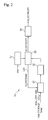
- FIG. 2 is a block diagram illustrating blocks composing the fuel cell module according to the embodiment of the present invention.
- the fuel cell module 20 according to the embodiment of the present invention includes a steam reformer 21, a separator 22, a fuel cell 23, a compressor 27, and an electricity storage unit 29.
- the boil-off gas occurring in the LNG storage tank 10 is supplied to the steam reformer 21.
- the steam reformer which produces synthetic gas by reforming the boil-off gas with steam has been proposed as a reformer.
- the reformer may include an autothermal reformer, a carbon dioxide reformer, a partial oxidation reformer, and a steam and carbon dioxide reformer.
- the autothermal reformer produces synthetic gas by autothermally reforming boil-off gas with steam and oxygen.
- the carbon dioxide reformer produces synthetic gas by reforming boil-off gas with carbon dioxide.
- the partial oxidation reformer produces synthetic gas by partial-oxidation reforming boil-off gas with oxygen.
- the steam and carbon dioxide reformer produces synthetic gas by reforming boil-off gas with steam and carbon dioxide.
- the process in which the steam reformer 21 produces synthetic gas by reforming the boil-off gas with steam may be expressed as a reaction formula below.
- the boil-off gas includes natural gas (CH 4 ) produced by the evaporation of LNG. CH 4 + H 2 O ⁇ 3H 2 + CO
- the steam reforming is caused by a catalyst such as nickel (Ni).
- the steam reformer 21 produces hydrogen (H 2 ) and carbon monoxide (CO) as synthetic gas. While the boil-off gas is reformed, other materials are subordinately produced. In this specification, only H 2 and CO are referred to as synthetic gas.
- the other materials include ash and hydrogen sulfide (H 2 S) produced when sulfur (S) contained in the boil-off gas is converted while the boil-off gas is reformed.
- the synthetic gas produced by reforming the boil-off gas through the steam reformer 21 is supplied as fuel to the fuel cell 23.
- the fuel cell 23 generates electricity through an electrochemical reaction of the synthetic gas supplied from the steam reformer 21.
- the separator 22 is installed at the rear stage of the steam reformer 21.
- the separator 22 serves to separate and remove the ash included in the other materials which are subordinately produced while the steam reformer 21 autothermally reforms the boil-off gas.
- the fuel cell 23 is installed at the rear stage of the separator 22.
- the compressor 27 serves to compress air and supply the compressed air to the fuel cell 23.
- the electricity storage unit 29 is connected to the fuel cell 23 and stores the electricity generated by the fuel cell 23.
- the steam reformer 21, the separator 22, the fuel cell 23, the compressor 27, and the electricity storage unit 29 are provided as one fuel cell module 20.
- the steam reformer, the separator, the compressor, the fuel cell, and the electricity storage unit are based on well-known techniques, and thus the detailed descriptions of the constructions thereof are omitted in this specification.
- the fuel cell 23 may include any one of a molten carbonate fuel cell (MCFC), a solid oxide fuel cell (SOFC), and a polymer electrolyte membrane/proton exchange membrane fuel cell (PEMFC).
- MCFC molten carbonate fuel cell
- SOFC solid oxide fuel cell
- PEMFC polymer electrolyte membrane/proton exchange membrane fuel cell
- the carbon monoxide supplied to the fuel cell 23 with the hydrogen is used for the reaction in which the carbon monoxide reacts with water at the anode to produce hydrogen.
- carbon dioxide CO 2
- the generated carbon dioxide is sent to the cathode and used for the reaction in which carbon trioxide (CO 3 -2 ) is produced at the cathode. That is, when the fuel cell 23 is the MCFC, the carbon dioxide produced during the electricity generation is circulated inside the fuel cell without being discharged to the outside.
- the carbon monoxide supplied to the fuel cell 23 with the hydrogen is used for the reaction in which the carbon monoxide reacts with water at the anode to produce hydrogen.
- carbon dioxide CO 2
- the produced carbon dioxide should be treated by a separate device.
- FIG. 3 is a block diagram illustrating blocks composing a fuel cell module according to another embodiment of the present invention.
- the same components as those of the fuel cell module 20 illustrated in FIG. 2 will be represented by the same reference numerals.
- the fuel cell module of FIG. 3 when the fuel cell 23 is the SOFC, the carbon dioxide produced during the electrochemical reaction of the synthetic gas in the fuel cell is not discharged to the air, because the carbon dioxide collector 25 and the carbon dioxide storage tank 26 are installed in the fuel cell module 20'. Therefore, it is possible to solve an environmental pollution problem caused by the discharge of the carbon dioxide.
- the fuel cell 23 is the SOFC
- the steam reformer 21, the separator 22, the fuel cell 23, the carbon dioxide collector 25, the carbon dioxide storage tank 26, the compressor 27, and the electricity storage unit 29 are provided as one fuel cell module 20', as illustrated in FIG. 3 .
- a water gas shift reactor 24 is installed at the rear stage of the separator 22, as illustrated in FIG. 4 .
- the water gas shift reactor 24 converts the carbon monoxide into carbon dioxide through a reaction between the carbon monoxide of the synthetic gas and water, thereby removing the carbon monoxide.
- FIG. 4 is a block diagram illustrating blocks composing a fuel cell module according to another embodiment of the present invention.
- the same components as those of the fuel cell module 20 illustrated in FIG. 2 will be represented by the same reference numerals.
- the water gas shift reactor 24 converts hydrogen sulfide (H 2 S), which is produced when sulfur (S) contained in boil-off gas is converted during the reforming process of the boil-off gas, into sulphuric acid (H 2 SO 4 ) through a reaction between the hydrogen sulfide (H 2 S) and water, thereby removing the hydrogen sulfide (H 2 S).
- H 2 S hydrogen sulfide
- the liquid sulphuric acid (H 2 SO 4 ) is discharged from the water gas shift reactor 24, and then stored in a separate container (not illustrated).
- the hydrogen (H 2 ) produced by the water gas shift reactor 24 is supplied as fuel to the fuel cell 23.
- the carbon dioxide collector 25 is installed at the rear stage of the water gas shift reactor 24.
- the carbon dioxide collector 25 serves to collect the carbon dioxide (CO 2 ) produced from the water gas shift reactor 24.
- the carbon dioxide collector 25 is connected to a carbon dioxide storage tank 26 for storing the carbon dioxide (CO 2 ) collected by the carbon dioxide collector 25.
- CO 2 carbon dioxide
- the hydrogen (H 2 ) produced by the water gas shift reactor 24 is supplied as fuel to the fuel cell 23.
- the fuel cell 23 is the PEMFC
- the steam reformer 21, the separator 22, the fuel cell 23, the water gas shift reactor 24, the carbon dioxide collector 25, the carbon dioxide storage tank 26, the compressor 27, and the electricity storage unit 29 are provided as one fuel cell module 20", as illustrated in FIG. 4 .
- the water gas shift reactor and the carbon dioxide collector are based on well-known techniques, and thus the detailed descriptions of the constructions thereof are omitted in this specification.
- steam H 2 O is subordinately produced.
- This steam is supplied to the steam reformer 21 through a steam supply line L23 and used for reforming boil-off gas in the steam reformer 21.
- the operation temperature of the MCFC corresponds to 650°C
- the operation temperature of the SOFC ranges from 650 to 1,000°C. Therefore, when the fuel cell is the MCFC or the SOFC, high-temperature heat is generated from the fuel cell. However, the high-temperature heat generated from the fuel cell is generally discarded.
- an embodiment of the present invention proposes a method for increasing generation efficiency by using the waste heat discarded by the fuel cell, when the fuel cell is the MCFC or the SOFC.
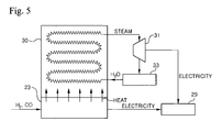
- FIG. 5 is a schematic view illustrating an apparatus for increasing generation efficiency by using waste heat discarded by a fuel cell, when the fuel cell is the MCFC or the SOFC.
- the fuel cell 23 includes a waste heat recovery system 30 attached thereto.
- the waste heat recovery system 30 serves to recover heat generated by the fuel cell 23.
- the waste heat recovery system 30 may include a heat exchanger.
- the waste heat recovery system 30 is connected to a steam turbine 31 and a condenser 33, and the steam turbine 31 is connected to the electricity storage unit 29.
- the waste heat recovery system 30 serves to convert water into high-temperature and high-pressure steam by using the heat generated from the fuel cell 23.
- the high-temperature and high-pressure steam produced by the waste heat recovery system 30 is transferred to the steam turbine 31, and rotates the steam turbine 31 to generate electricity.
- the electricity generated by the steam turbine 31 is stored in the electricity storage unit 29.
- the steam After rotating the steam turbine 31, the steam is sent to the condenser 33 to condense the steam.
- the condensed water is sent to the waste heat recovery system 30.
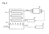
- FIG. 6 illustrates an apparatus which is constructed in such a manner that steam produced by the waste heat recovery system 30 is sent to a steam-using place 32 inside the LNG carrier. Therefore, the waste heat recovery system 30 is connected to the steam-using place 32 inside the LNG carrier and the condenser 33. After being used in the steam-using place 32, the steam is sent to the condenser 33 to condense the steam. Then, the condensed water is sent to the waste heat recovery system 30.
- the fuel cell is the MCFC or the SOFC
- a part of the synthetic gas supplied to the fuel cell is discharged in a high-temperature state without electrochemically reacting in the fuel cell.
- the high-temperature synthetic gas discharged from the fuel cell may be used to increase generation efficiency.
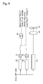
- FIG. 7 is a schematic view illustrating an apparatus for increasing generation efficiency by using high-temperature synthetic gas discharged from the fuel cell, when the fuel cell is the MCFC or the SOFC.
- the fuel cell 23 is connected to a burner 80 to which the high-temperature synthetic gas discharged from the fuel cell 23 is supplied.
- the burner 80 is connected to a gas turbine 81, and the gas turbine 81 is connected to the electricity storage unit 29. Furthermore, since the burner 80 and the gas turbine 81 are connected to the compressor 27, the compressor 27 supplies high-pressure air to the burner 80 and the gas turbine 81.
- the burner 80 serves to burn the high-temperature synthetic gas discharged from the fuel cell 23 with the high-temperature air and converts the synthetic gas into high-temperature and high-pressure gas.
- the high-temperature and high-pressure gas produced from the burner 80 is sent to the gas turbine 81, and rotates the gas turbine 81 to generate electricity.
- the electricity generated by the gas turbine 81 is stored in the electricity storage unit 29.
- the gas After rotating the gas turbine 81, the gas is discharged to the outside.
- FIG. 8 is a schematic view illustrating the connection relationships among the respective components inside the LNG carrier, when the propulsion system of the LNG carrier according to the embodiment of the present invention is a dual fuel electricity propulsion system.
- the dual fuel electricity propulsion system includes a dual fuel engine 41, a generator 43, an AC/AC converter 45, a transformer 47, and a propulsion electromotor 49.
- the propulsion electromotor 49 serves to drive the propeller 50 through a clutch 48.
- the generator 43 is connected to electricity facilities inside the LNG carrier and the propulsion electromotor 49.
- the electricity facilities inside the LNG carrier include basic electricity facilities of the LNG carrier and cargo-related electricity facilities.
- FIG. 8 illustrates that two dual fuel engines 41 and two generators 43 are installed, and one fuel cell module 20 is installed.
- the fuel cell module 20 is connected in parallel to the generator 43. Therefore, the electricity generated from the fuel cell module 20 is joined with the electricity generated from the generator 43 and then supplied to the electricity facilities inside the LNG carrier and the propulsion electromotor 49.
- the fuel cell module 20 and the generators 43 are connected in parallel to a battery 60, and DC/AC converters 70 are disposed at the rear stages of the fuel cell module 20 and the battery 60, respectively.
- the dual fuel cell engine 41 which has a large electricity generation capacity and discharges a large amount of waste gas may not be operated, but only the fuel cell module 20 which has a small electricity generation capacity and is constructed in an environmentally-friendly manner may be operated to drive the propulsion electromotor 49 and the electricity facilities inside the LNG carrier by using only the electricity generated from the fuel cell module 20 and the electricity stored in the battery 60. Meanwhile, when the LNG carrier normally sails, the power consumption thereof is large, and the discharge of waste gas is relatively free.
- both of the dual fuel engine 41 and the fuel cell module 20 may be operated to drive the propulsion electromotor 49 and the electricity facilities inside the LNG carrier by using the electricity generated by the dual fuel engine 41 and the fuel cell module 20. At this time, the electricity generated by the dual fuel engine 41 and the fuel cell module 20 charges the battery 60.
- the LNG carrier includes the dual fuel electricity propulsion system as a propulsion system
- three dual fuel engines and three generators were installed in the related art, but two dual fuel engines 41, two generators 43, and one fuel cell module 20 are installed in the embodiment of the present invention.
- FIG. 9 is a schematic view illustrating the connection relationships among components inside the LNG carrier, when the LNG carrier according to the embodiment of the present invention includes a diesel engine propulsion system as a propulsion system.
- the diesel engine propulsion system includes a diesel engine 42.
- the diesel engine 42 drives the propeller 50 through a clutch 48.
- FIG. 9 illustrates that two fuel cell modules 20 are installed.
- the fuel cell modules 20 are connected to electricity facilities inside the LNG carrier, that is, basic electricity facilities inside the LNG carrier and cargo-related electricity facilities. Therefore, electricity generated by the fuel cell module 20 is supplied to the electricity facilities inside the LNG carrier, that is, basic electricity facilities inside the LNG carrier and cargo-related electricity facilities.
- DC/AC converters 70 are respectively disposed.
- the LNG carrier includes the diesel engine propulsion system as a propulsion system
- two generation diesel engines and two generators were installed in the related art, but only two fuel cell modules 20 are installed without the generation diesel engines and the generators in the embodiment of the present invention.
- the propulsion diesel engine may include a Man B&W engine gas injection (MEGI) engine which is a high-pressure gas injection engine made by Man B&W Diesel.
- MEGI Man B&W engine gas injection
- the boil-off gas occurring in the LNG carrier may be reformed to produce fuel for the fuel cell, and the fuel produced in such a manner may be continuously supplied to the fuel cell. Therefore, the fuel cell may be adopted as a system for producing electricity required by a large vessel such as an LNG carrier, which sails a long distance.
- the LNG carrier includes the fuel combustion engine, such as the dual fuel engine or the propulsion diesel engine, and the fuel cell module which is constructed to continuously supply the fuel, which is obtained by reforming the boil-off gas occurring in the LNG carrier, to the fuel cell.
- the LNG carrier may not include a separate fuel combustion engine such as the dual fuel engine or the diesel engine, but may include only the fuel cell module. In this case, only the electricity generated by the fuel cell module may be used to drive the propulsion electromotor to propel the LNG carrier and operate the electricity facilities inside the LNG carrier.
Landscapes
- Chemical & Material Sciences (AREA)
- Engineering & Computer Science (AREA)
- Chemical Kinetics & Catalysis (AREA)
- Electrochemistry (AREA)
- Combustion & Propulsion (AREA)
- General Chemical & Material Sciences (AREA)
- Life Sciences & Earth Sciences (AREA)
- Sustainable Development (AREA)
- Sustainable Energy (AREA)
- Ocean & Marine Engineering (AREA)
- Mechanical Engineering (AREA)
- Manufacturing & Machinery (AREA)
- Organic Chemistry (AREA)
- Health & Medical Sciences (AREA)
- General Health & Medical Sciences (AREA)
- Inorganic Chemistry (AREA)
- Fuel Cell (AREA)
- Hydrogen, Water And Hydrids (AREA)
Abstract
Description
- The present invention relates to an apparatus and method for generating electricity in a liquefied natural gas (LNG) carrier, and more particularly, to an apparatus and method for generating electricity required in an LNG carrier which stores LNG, which is obtained by liquefying natural gas to ultra low temperature in a gas field, in an LNG storage tank and carries the stored LNG.
- In general, an LNG carrier is a vessel which stores LNG, which is obtained by liquefying natural gas to an ultra-low temperature in a gas field is stored, in an LNG storage tank and carries the stored LNG.
- Examples of a propulsion system of the LNG carrier may include a steam turbine propulsion system using steam, a diesel engine propulsion system having a diesel engine for propulsion, and a dual fuel electricity propulsion system having a dual fuel engine, a generator, and a propulsion electromotor. The steam turbine propulsion system has low propulsion efficiency. Therefore, the diesel engine propulsion system or the dual fuel electricity propulsion system having high propulsion efficiency is mainly used as the propulsion system of the LNG carrier.
- The LNG carrier, to which the diesel engine propulsion system is applied, includes a generation diesel engine and a generator which are separately installed therein, in order to supply electricity to electricity facilities inside the LNG carrier, that is, basic electricity facilities and cargo-related electricity facilities inside the LNG carrier.
- In the case of the LNG carrier to which the dual fuel electricity propulsion system is applied, the dual fuel engine and the generator generate electricity and supply the generated electricity to electricity facilities inside the LNG carrier as well as the propulsion electromotor. In order to obtain the required electricity, an increased number of dual fuel engines and generators are installed and operated.
- Meanwhile, an environment-friendly fuel cell may be adopted to generate electricity required in a vessel. The fuel cell obtains electricity through an electrochemical reaction of fuel-cell fuel, for example, hydrogen or synthetic gas having hydrogen. Conventionally, when the fuel-cell fuel is hydrogen, a hydrogen tank is installed in the vessel to store the hydrogen, and the stored hydrogen is supplied to the fuel cell from the hydrogen tank. However, since such a hydrogen tank has a limited size, the amount of hydrogen stored in the hydrogen tank may be limited.
- Therefore, since the vessel including the conventional fuel cell has a limitation in supplying fuel-cell fuel, only fuel cells having a small capacity have been inevitably used as the conventional fuel cell, and the conventional fuel cell has been applied only to small vessels which sail a short distance. Furthermore, since the electricity generation capacity of the fuel cell is small, there is a limitation in using electricity generated by the fuel cell for electricity facilities inside the vessel. In particular, when the vessel having the conventional fuel cell operates a propulsion electromotor by using only the electricity generated from the fuel cell without including a separate generation engine, electromotors having a small output are inevitably used as the propulsion electromotor, because the electricity generation capacity of the fuel cell is small. Accordingly, since the speed of the vessel does not only decrease, but also most power is consumed by the propulsion electromotor, there is a larger limitation in using the electricity generated by the fuel cell for the electricity facilities inside the vessel.
- An embodiment of the present invention is directed to an apparatus and method for generating electricity, which is constructed to continuously supply fuel to a fuel cell during the operation of a vessel, when the fuel cell is adopted as a device for generating electricity required by a large vessel, such as an LNG carrier, which sails a long distance.
- According to an aspect of the present invention, there is provided an apparatus for generating electricity required by an LNG carrier which stores LNG, which is obtained by liquefying natural gas to ultra low temperature in a gas field, in an LNG storage tank and carries the stored LNG. The apparatus includes: a reformer reforming boil-off gas occurring in the LNG storage tank and producing synthetic gas; and a fuel cell generating electricity through an electrochemical reaction of the synthetic gas produced by the reformer.
- The reformer may include a steam reformer which reforms the boil-off gas with steam and produces the synthetic gas.
- The apparatus may further include a steam supply line supplying steam to the steam reformer, the steam subordinately occurring during the electrochemical reaction of the synthetic gas in the fuel cell.
- The apparatus may further include a separator installed at a rear stage of the steam reformer and separating ash which subordinately occurs while the boil-off gas is reformed.
- The apparatus may further include a compressor compressing air and supplying the compressed air to the fuel cell.
- The apparatus may further include an electricity storage unit connected to the fuel cell and storing the electricity generated by the fuel cell.
- The reformer, the separator, the fuel cell, the compressor, and the electricity storage unit may be provided as one fuel cell module.
- The fuel cell may include any one of a molten carbonate fuel cell (MCFC), a solid oxide fuel cell (SOFC), and a polymer electrolyte membrane/proton exchange membrane fuel cell (PEMFC).
- When the fuel cell is the SOFC, the fuel cell may include: a carbon dioxide collector collecting carbon dioxide which occurs while synthetic gas electrochemically reacts in the SOFC; and a carbon dioxide storage tank storing the carbon dioxide collected by the carbon dioxide collector.
- The apparatus may further include a water gas shift reactor installed at a rear stage of the separator, causing carbon monoxide of the synthetic gas to react with water, and removing the carbon monoxide by converting the carbon monoxide into carbon dioxide, when the fuel cell is the PEMFC.
- The apparatus may further include a carbon dioxide collector installed at a rear stage of the water gas shift reactor and collecting carbon dioxide which occurs while the water gas shift reactor removes the carbon monoxide; and a carbon dioxide storage tank storing the carbon dioxide collected by the carbon dioxide collector.
- The reformer, the separator, the fuel cell, the carbon dioxide collector, the carbon dioxide storage tank, the compressor, and the electricity storage unit may be provided as one fuel cell module.
- The reformer, the separator, the fuel cell, the water gas shift reactor, the carbon dioxide collector, the carbon dioxide storage tank, the compressor, and the electricity storage unit may be provided as one fuel cell module.
- The LNG carrier may include a propulsion system.
- The propulsion system may include a dual fuel electricity propulsion system having a dual fuel engine, a generator, and a propulsion electromotor, the generator may be connected to electricity facilities inside the LNG carrier and the propulsion electromotor, and the fuel cell module may be connected in parallel to the generator.
- The propulsion system may include a diesel engine propulsion system having a propulsion diesel engine, and the fuel cell module may be connected to electricity facilities inside the LNG carrier.
- The propulsion diesel engine may include a Man B&W engine gas injection (MEGI) engine.
- When the fuel cell is the MCFC or the SOFC, the fuel cell may include a waste heat recovery system attached thereto and recovering heat produced from the fuel cell, the waste heat recovery system may be connected to a steam turbine and a condenser, and the steam turbine may be connected to the electricity storage unit.
- When the fuel cell is the MCFC or the SOFC, the fuel cell may include a waste heat recovery system attached thereto and recovering heat produced from the fuel cell, and the waste heat recovery system may be connected to steam-using places inside the LNG carrier and a condenser.
- When the fuel cell is the MCFC or the SOFC, the fuel cell may be connected to a burner to which high-temperature synthetic gas discharged from the fuel cell is supplied, the burner may be connected to a gas turbine, the gas turbine may be connected to an electricity storage unit, and the burner and the gas turbine may be connected to the compressor.
- According to another aspect of the present invention, there is provided a method for generating electricity required by a LNG carrier which stores LNG, which is obtained by liquefying natural gas to ultra low temperature in a gas field, in an LNG storage tank and carries the stored LNG. The method includes: installing a fuel cell in the LNG carrier, the fuel cell generating electricity through an electrochemical reaction of synthetic gas; reforming boil-off gas occurring in the LNG storage tank and producing the synthetic gas; and supplying the produced synthetic gas to the fuel cell to generate electricity through an electrochemical reaction of the synthetic gas.
- The boil-off gas may be reformed with steam to produce the synthetic gas.
- Steam produced during the electrochemical reaction of the synthetic gas in the fuel cell may be used for the steam reforming.
- When the fuel cell is the MCFC or the SOFC, carbon monoxide of the synthetic gas and hydrogen may be supplied to the fuel cell.
- When the fuel cell is the PEMFC, carbon monoxide of the synthetic gas may be removed, and only hydrogen may be supplied to the fuel cell.
- When the fuel cell is the MCFC or the SOFC, heat produced from the fuel cell may be used to produce steam, and the produced steam may be used to rotate a steam turbine to generate electricity.
- When the fuel cell is the MCFC or the SOFC, the heat produced from the fuel cell may be used to produce steam, and the produced steam may be used for steam-using places inside the LNG carrier.
- When the fuel cell is the MCFC or the SOFC, high-temperature synthetic gas discharged from the fuel cell may be burned to produce high-temperature and high-pressure gas, and the produced high-temperature and high-pressure gas may be used to rotate a gas turbine to generate electricity.
- The LNG carrier may be propelled by a propulsion system.
- The propulsion system may include a dual fuel electricity propulsion system having a dual fuel engine, a generator, and a propulsion electromotor, and the electricity produced by the fuel cell may be joined with electricity generated by the generator and then supplied to electricity facilities inside the LNG carrier and the propulsion electromotor.
- The propulsion system may include a diesel engine propulsion system having a propulsion diesel engine, and the electricity produced by the fuel cell may be supplied to electricity facilities inside the LNG carrier.
- It should be understood that different embodiments of the invention, including those described under different aspects of the invention, are meant to be generally applicable to all aspects of the invention. Any embodiment may be combined with any other embodiment unless inappropriate. All examples are illustrative and non-limiting.
- According to the embodiments of the present invention, the boil-off gas occurring in the LNG carrier may be reformed to produce fuel for the fuel cell, and the fuel produced in such a manner may be continuously supplied to the fuel cell. Therefore, the fuel cell may be adopted as a system for producing electricity required by a large vessel such as an LNG carrier, which sails a long distance.
-
-
FIG. 1 is a schematic view of an LNG carrier according to an embodiment of the present invention. -
FIG. 2 is a block diagram illustrating blocks composing a fuel cell module according to an embodiment of the present invention. -
FIG. 3 is a block diagram illustrating blocks composing a fuel cell module according to another embodiment of the present invention. -
FIG. 4 is a block diagram illustrating blocks composing a fuel cell module according to another embodiment of the present invention. -
FIG. 5 is a schematic view illustrating an apparatus for increasing generation efficiency by using waste heat discarded by the fuel cell according to the embodiment of the present invention. -
FIG. 6 schematically illustrates an apparatus which is constructed in such a manner that waste heat discarded by the fuel cell according to the embodiment of the present invention is used in a steam-using place inside the LNG carrier. -
FIG. 7 is a schematic view illustrating an apparatus for increasing generation efficiency by using high-temperature synthetic gas discharged from the fuel cell according to the embodiment of the present invention. -
FIG. 8 is a schematic view illustrating the connection relationships among the respective components inside the LNG carrier, when a propulsion system of the LNG carrier according to the embodiment of the present invention is a dual fuel electricity propulsion system. -
FIG. 9 is a schematic view illustrating the connection relationships among the respective components inside the LNG carrier, when a propulsion system of the LNG carrier according to the embodiment of the present invention is a diesel engine propulsion system. - Exemplary embodiments of the present invention will be described below in more detail with reference to the accompanying drawings. The present invention may, however, be embodied in different forms and should not be constructed as limited to the embodiments set forth herein. Rather, these embodiments are provided so that this disclosure will be thorough and complete, and will fully convey the scope of the present invention to those skilled in the art. Throughout the disclosure, like reference numerals refer to like parts throughout the various figures and embodiments of the present invention.
-
FIG. 1 is a schematic view of an LNG carrier according to an embodiment of the present invention. The LNG carrier 1 ofFig. 1 includes anLNG storage tank 10, afuel cell module 20, adiesel storage tank 30, apropulsion system 40, and apropeller 50. - The
LNG storage tank 10 stores LNG which is obtained by liquefying natural gas to ultra low temperature. Since the liquefaction temperature of natural gas is as low as - 163°C at normal pressure, LNG tends to evaporate even when the temperature thereof is slightly higher than -163°C at normal pressure. - Although the
LNG storage tank 10 is thermally insulated, external heat is continuously transferred to the LNG. Therefore, while the LNG is carried by the LNG carrier, the LNG is continuously gasified inside theLNG storage tank 10, and thus boil-off gas occurs inside theLNG storage tank 10. - The boil-off gas occurring in the
LNG storage tank 10 is supplied to thefuel cell module 20 and thepropulsion system 40. -
FIG. 2 is a block diagram illustrating blocks composing the fuel cell module according to the embodiment of the present invention. Referring toFig. 2 , thefuel cell module 20 according to the embodiment of the present invention includes asteam reformer 21, aseparator 22, afuel cell 23, acompressor 27, and anelectricity storage unit 29. - The boil-off gas occurring in the
LNG storage tank 10 is supplied to thesteam reformer 21. In this embodiment, the steam reformer which produces synthetic gas by reforming the boil-off gas with steam has been proposed as a reformer. However, the reformer may include an autothermal reformer, a carbon dioxide reformer, a partial oxidation reformer, and a steam and carbon dioxide reformer. The autothermal reformer produces synthetic gas by autothermally reforming boil-off gas with steam and oxygen. The carbon dioxide reformer produces synthetic gas by reforming boil-off gas with carbon dioxide. The partial oxidation reformer produces synthetic gas by partial-oxidation reforming boil-off gas with oxygen. The steam and carbon dioxide reformer produces synthetic gas by reforming boil-off gas with steam and carbon dioxide. - The process in which the
steam reformer 21 produces synthetic gas by reforming the boil-off gas with steam may be expressed as a reaction formula below. The boil-off gas includes natural gas (CH4) produced by the evaporation of LNG.
CH4 + H2O → 3H2 + CO
- Here, the steam reforming is caused by a catalyst such as nickel (Ni). The
steam reformer 21 produces hydrogen (H2) and carbon monoxide (CO) as synthetic gas. While the boil-off gas is reformed, other materials are subordinately produced. In this specification, only H2 and CO are referred to as synthetic gas. The other materials include ash and hydrogen sulfide (H2S) produced when sulfur (S) contained in the boil-off gas is converted while the boil-off gas is reformed. - The synthetic gas produced by reforming the boil-off gas through the
steam reformer 21 is supplied as fuel to thefuel cell 23. Thefuel cell 23 generates electricity through an electrochemical reaction of the synthetic gas supplied from thesteam reformer 21. - The
separator 22 is installed at the rear stage of thesteam reformer 21. Theseparator 22 serves to separate and remove the ash included in the other materials which are subordinately produced while thesteam reformer 21 autothermally reforms the boil-off gas. - The
fuel cell 23 is installed at the rear stage of theseparator 22. - The
compressor 27 serves to compress air and supply the compressed air to thefuel cell 23. - The
electricity storage unit 29 is connected to thefuel cell 23 and stores the electricity generated by thefuel cell 23. - The
steam reformer 21, theseparator 22, thefuel cell 23, thecompressor 27, and theelectricity storage unit 29 are provided as onefuel cell module 20. - Furthermore, the steam reformer, the separator, the compressor, the fuel cell, and the electricity storage unit are based on well-known techniques, and thus the detailed descriptions of the constructions thereof are omitted in this specification.
- Meanwhile, the
fuel cell 23 may include any one of a molten carbonate fuel cell (MCFC), a solid oxide fuel cell (SOFC), and a polymer electrolyte membrane/proton exchange membrane fuel cell (PEMFC). - When the
fuel cell 22 is the MCFC, carbon monoxide and hydrogen are supplied to thefuel cell 23 without removing the carbon monoxide from the synthetic gas. A process in which the MCFC generates electricity through an electrochemical reaction of hydrogen and carbon monoxide as synthetic gas may be expressed as a reaction formula below.
Anode: H2 + CO3 -2 → H2O + CO2 + 2e-
CO + CO3 -2 → 2CO2 + 2e-
CO + H2O → H2 + CO2
Cathode: 0.5O2 + CO2 + 2e- → CO3 -2
Entire reaction in fuel cell: H2 + 0.5O2 + CO2 → H2O + CO2
- Here, the carbon monoxide supplied to the
fuel cell 23 with the hydrogen is used for the reaction in which the carbon monoxide reacts with water at the anode to produce hydrogen. At this time, carbon dioxide (CO2) is generated. The generated carbon dioxide is sent to the cathode and used for the reaction in which carbon trioxide (CO3 -2) is produced at the cathode. That is, when thefuel cell 23 is the MCFC, the carbon dioxide produced during the electricity generation is circulated inside the fuel cell without being discharged to the outside. - Furthermore, when the fuel cell is the SOFC, carbon monoxide and hydrogen are supplied to the
fuel cell 23 without removing the carbon monoxide from the synthetic gas. A process in which the SOFC generates electricity through an electrochemical reaction of hydrogen and carbon monoxide as synthetic gas may be expressed as a reaction formula below.
Anode: H2 + O-2 → H2O + 2e-
CO + O-2 → CO2 + 2e-
CO + H2O → H2 + CO2
Cathode: 0.5O2 + 2e- → O-2
Entire reaction in fuel cell: H2 + 0.5O2 → H2O
- Here, the carbon monoxide supplied to the
fuel cell 23 with the hydrogen is used for the reaction in which the carbon monoxide reacts with water at the anode to produce hydrogen. At this time, carbon dioxide (CO2) is produced. The produced carbon dioxide should be treated by a separate device. - Referring to
FIG. 3 , when thefuel cell 23 is the SOFC, thefuel cell 23 includes acarbon dioxide collector 25 to collect carbon dioxide, in order to treat the carbon dioxide produced during the process in which the synthetic gas electrochemically reacts in the fuel cell. Thecarbon dioxide collector 25 includes a carbondioxide storage tank 26 for storing carbon dioxide collected by thecarbon dioxide collector 25.FIG. 3 is a block diagram illustrating blocks composing a fuel cell module according to another embodiment of the present invention. In the fuel cell module 20' illustrated inFIG. 3 , the same components as those of thefuel cell module 20 illustrated inFIG. 2 will be represented by the same reference numerals. - According to the fuel cell module of
FIG. 3 , when thefuel cell 23 is the SOFC, the carbon dioxide produced during the electrochemical reaction of the synthetic gas in the fuel cell is not discharged to the air, because thecarbon dioxide collector 25 and the carbondioxide storage tank 26 are installed in the fuel cell module 20'. Therefore, it is possible to solve an environmental pollution problem caused by the discharge of the carbon dioxide. - Furthermore, when the
fuel cell 23 is the SOFC, thesteam reformer 21, theseparator 22, thefuel cell 23, thecarbon dioxide collector 25, the carbondioxide storage tank 26, thecompressor 27, and theelectricity storage unit 29 are provided as one fuel cell module 20', as illustrated inFIG. 3 . - Meanwhile, when the
fuel cell 23 is the PEMFC, carbon monoxide is removed from the synthetic gas, and only hydrogen is supplied to thefuel cell 23. A process in which the PEMFC generates electricity through an electrochemical reaction of hydrogen may be expressed as a reaction formula below.
Anode: H2 → 2H+ + 2e-
Cathode: 0.5O2 + 2H+ + 2e- → H2O
Entire reaction in fuel cell: H2 + 0.5O2 → H2O
- Here, in order to remove the carbon monoxide from the synthetic gas, a water
gas shift reactor 24 is installed at the rear stage of theseparator 22, as illustrated inFIG. 4 . The watergas shift reactor 24 converts the carbon monoxide into carbon dioxide through a reaction between the carbon monoxide of the synthetic gas and water, thereby removing the carbon monoxide. -
FIG. 4 is a block diagram illustrating blocks composing a fuel cell module according to another embodiment of the present invention. In thefuel cell module 20" illustrated inFIG. 4 , the same components as those of thefuel cell module 20 illustrated inFIG. 2 will be represented by the same reference numerals. - The water
gas shift reactor 24 converts hydrogen sulfide (H2S), which is produced when sulfur (S) contained in boil-off gas is converted during the reforming process of the boil-off gas, into sulphuric acid (H2SO4) through a reaction between the hydrogen sulfide (H2S) and water, thereby removing the hydrogen sulfide (H2S). The liquid sulphuric acid (H2SO4) is discharged from the watergas shift reactor 24, and then stored in a separate container (not illustrated). - The processes in which the water
gas shift reactor 24 converts the carbon monoxide and the hydrogen sulfide of the synthetic gas into carbon dioxide and sulphuric acid, respectively, may be expressed as reaction formulas below.
CO + H2O → CO2 + H2
H2S + 4H2O → H2SO4 + 4H2
- The hydrogen (H2) produced by the water
gas shift reactor 24 is supplied as fuel to thefuel cell 23. - The
carbon dioxide collector 25 is installed at the rear stage of the watergas shift reactor 24. Thecarbon dioxide collector 25 serves to collect the carbon dioxide (CO2) produced from the watergas shift reactor 24. - The
carbon dioxide collector 25 is connected to a carbondioxide storage tank 26 for storing the carbon dioxide (CO2) collected by thecarbon dioxide collector 25. According to thefuel cell module 20" ofFIG. 4 , when thefuel cell 23 is the PEMFC, the carbon dioxide produced during the process of removing the carbon monoxide contained in the synthetic gas supplied to thefuel cell 23 is not discharged to the air, because thecarbon diode collector 25 and the carbondioxide storage tank 26 are installed in thefuel cell module 20". Therefore, it is possible to solve an environmental pollution problem caused by the discharge of the carbon dioxide. - The hydrogen (H2) produced by the water
gas shift reactor 24 is supplied as fuel to thefuel cell 23. - Furthermore, when the
fuel cell 23 is the PEMFC, thesteam reformer 21, theseparator 22, thefuel cell 23, the watergas shift reactor 24, thecarbon dioxide collector 25, the carbondioxide storage tank 26, thecompressor 27, and theelectricity storage unit 29 are provided as onefuel cell module 20", as illustrated inFIG. 4 . - The water gas shift reactor and the carbon dioxide collector are based on well-known techniques, and thus the detailed descriptions of the constructions thereof are omitted in this specification.
- While the synthetic gas electrochemically reacts in the
fuel cell 23, steam (H2O is subordinately produced. This steam is supplied to thesteam reformer 21 through a steam supply line L23 and used for reforming boil-off gas in thesteam reformer 21. - The operation temperature of the MCFC corresponds to 650°C, and the operation temperature of the SOFC ranges from 650 to 1,000°C. Therefore, when the fuel cell is the MCFC or the SOFC, high-temperature heat is generated from the fuel cell. However, the high-temperature heat generated from the fuel cell is generally discarded.
- Accordingly, an embodiment of the present invention proposes a method for increasing generation efficiency by using the waste heat discarded by the fuel cell, when the fuel cell is the MCFC or the SOFC.
-
FIG. 5 is a schematic view illustrating an apparatus for increasing generation efficiency by using waste heat discarded by a fuel cell, when the fuel cell is the MCFC or the SOFC. Referring toFIG. 5 , thefuel cell 23 includes a wasteheat recovery system 30 attached thereto. The wasteheat recovery system 30 serves to recover heat generated by thefuel cell 23. The wasteheat recovery system 30 may include a heat exchanger. The wasteheat recovery system 30 is connected to asteam turbine 31 and acondenser 33, and thesteam turbine 31 is connected to theelectricity storage unit 29. - The waste
heat recovery system 30 serves to convert water into high-temperature and high-pressure steam by using the heat generated from thefuel cell 23. - The high-temperature and high-pressure steam produced by the waste
heat recovery system 30 is transferred to thesteam turbine 31, and rotates thesteam turbine 31 to generate electricity. The electricity generated by thesteam turbine 31 is stored in theelectricity storage unit 29. - After rotating the
steam turbine 31, the steam is sent to thecondenser 33 to condense the steam. The condensed water is sent to the wasteheat recovery system 30. - Furthermore, the high-temperature and high-pressure steam produced by the waste
heat recovery system 30 may be used in a steam-using place inside the vessel.FIG. 6 illustrates an apparatus which is constructed in such a manner that steam produced by the wasteheat recovery system 30 is sent to a steam-usingplace 32 inside the LNG carrier. Therefore, the wasteheat recovery system 30 is connected to the steam-usingplace 32 inside the LNG carrier and thecondenser 33. After being used in the steam-usingplace 32, the steam is sent to thecondenser 33 to condense the steam. Then, the condensed water is sent to the wasteheat recovery system 30. - Furthermore, when the fuel cell is the MCFC or the SOFC, a part of the synthetic gas supplied to the fuel cell is discharged in a high-temperature state without electrochemically reacting in the fuel cell. The high-temperature synthetic gas discharged from the fuel cell may be used to increase generation efficiency.
-
FIG. 7 is a schematic view illustrating an apparatus for increasing generation efficiency by using high-temperature synthetic gas discharged from the fuel cell, when the fuel cell is the MCFC or the SOFC. Referring toFIG. 7 , thefuel cell 23 is connected to aburner 80 to which the high-temperature synthetic gas discharged from thefuel cell 23 is supplied. Theburner 80 is connected to agas turbine 81, and thegas turbine 81 is connected to theelectricity storage unit 29. Furthermore, since theburner 80 and thegas turbine 81 are connected to thecompressor 27, thecompressor 27 supplies high-pressure air to theburner 80 and thegas turbine 81. - The
burner 80 serves to burn the high-temperature synthetic gas discharged from thefuel cell 23 with the high-temperature air and converts the synthetic gas into high-temperature and high-pressure gas. - The high-temperature and high-pressure gas produced from the
burner 80 is sent to thegas turbine 81, and rotates thegas turbine 81 to generate electricity. The electricity generated by thegas turbine 81 is stored in theelectricity storage unit 29. - After rotating the
gas turbine 81, the gas is discharged to the outside. -
FIG. 8 is a schematic view illustrating the connection relationships among the respective components inside the LNG carrier, when the propulsion system of the LNG carrier according to the embodiment of the present invention is a dual fuel electricity propulsion system. - In the LNG carrier, the dual fuel electricity propulsion system includes a
dual fuel engine 41, agenerator 43, an AC/AC converter 45, atransformer 47, and apropulsion electromotor 49. Thepropulsion electromotor 49 serves to drive thepropeller 50 through a clutch 48. - The
generator 43 is connected to electricity facilities inside the LNG carrier and thepropulsion electromotor 49. The electricity facilities inside the LNG carrier include basic electricity facilities of the LNG carrier and cargo-related electricity facilities.FIG. 8 illustrates that twodual fuel engines 41 and twogenerators 43 are installed, and onefuel cell module 20 is installed. Thefuel cell module 20 is connected in parallel to thegenerator 43. Therefore, the electricity generated from thefuel cell module 20 is joined with the electricity generated from thegenerator 43 and then supplied to the electricity facilities inside the LNG carrier and thepropulsion electromotor 49. Thefuel cell module 20 and thegenerators 43 are connected in parallel to abattery 60, and DC/AC converters 70 are disposed at the rear stages of thefuel cell module 20 and thebattery 60, respectively. For example, when the LNG carrier enters or leaves a port, the power consumption thereof is small, and the discharge of waste gas around the port needs to be reduced. Therefore, the dualfuel cell engine 41 which has a large electricity generation capacity and discharges a large amount of waste gas may not be operated, but only thefuel cell module 20 which has a small electricity generation capacity and is constructed in an environmentally-friendly manner may be operated to drive thepropulsion electromotor 49 and the electricity facilities inside the LNG carrier by using only the electricity generated from thefuel cell module 20 and the electricity stored in thebattery 60. Meanwhile, when the LNG carrier normally sails, the power consumption thereof is large, and the discharge of waste gas is relatively free. Therefore, both of thedual fuel engine 41 and thefuel cell module 20 may be operated to drive thepropulsion electromotor 49 and the electricity facilities inside the LNG carrier by using the electricity generated by thedual fuel engine 41 and thefuel cell module 20. At this time, the electricity generated by thedual fuel engine 41 and thefuel cell module 20 charges thebattery 60. - When the LNG carrier includes the dual fuel electricity propulsion system as a propulsion system, three dual fuel engines and three generators were installed in the related art, but two
dual fuel engines 41, twogenerators 43, and onefuel cell module 20 are installed in the embodiment of the present invention. -
FIG. 9 is a schematic view illustrating the connection relationships among components inside the LNG carrier, when the LNG carrier according to the embodiment of the present invention includes a diesel engine propulsion system as a propulsion system. - In the LNG carrier, the diesel engine propulsion system includes a diesel engine 42. The diesel engine 42 drives the
propeller 50 through a clutch 48. -
FIG. 9 illustrates that twofuel cell modules 20 are installed. Thefuel cell modules 20 are connected to electricity facilities inside the LNG carrier, that is, basic electricity facilities inside the LNG carrier and cargo-related electricity facilities. Therefore, electricity generated by thefuel cell module 20 is supplied to the electricity facilities inside the LNG carrier, that is, basic electricity facilities inside the LNG carrier and cargo-related electricity facilities. At the rear stages of thefuel cell modules 20, DC/AC converters 70 are respectively disposed. - When the LNG carrier includes the diesel engine propulsion system as a propulsion system, two generation diesel engines and two generators were installed in the related art, but only two
fuel cell modules 20 are installed without the generation diesel engines and the generators in the embodiment of the present invention. - Here, the propulsion diesel engine may include a Man B&W engine gas injection (MEGI) engine which is a high-pressure gas injection engine made by Man B&W Diesel.
- According to the embodiments of the present invention, the boil-off gas occurring in the LNG carrier may be reformed to produce fuel for the fuel cell, and the fuel produced in such a manner may be continuously supplied to the fuel cell. Therefore, the fuel cell may be adopted as a system for producing electricity required by a large vessel such as an LNG carrier, which sails a long distance.
- In the above-described embodiments, the LNG carrier includes the fuel combustion engine, such as the dual fuel engine or the propulsion diesel engine, and the fuel cell module which is constructed to continuously supply the fuel, which is obtained by reforming the boil-off gas occurring in the LNG carrier, to the fuel cell. The LNG carrier may not include a separate fuel combustion engine such as the dual fuel engine or the diesel engine, but may include only the fuel cell module. In this case, only the electricity generated by the fuel cell module may be used to drive the propulsion electromotor to propel the LNG carrier and operate the electricity facilities inside the LNG carrier.
- While the present invention has been described with respect to the specific embodiments, it will be apparent to those skilled in the art that various changes and modifications may be made without departing from the spirit and scope of the invention as defined in the following claims.
Claims (31)
- An apparatus for generating electricity required by a liquefied natural gas (LNG) carrier which stores LNG, which is obtained by liquefying natural gas to ultra low temperature in a gas field, in an LNG storage tank and carries the stored LNG, the apparatus comprising:a reformer reforming boil-off gas occurring in the LNG storage tank and producing synthetic gas; anda fuel cell generating electricity through an electrochemical reaction of the synthetic gas produced by the reformer.
- The apparatus according to claim 1, wherein the reformer comprises a steam reformer which reforms the boil-off gas with steam and produces the synthetic gas.
- The apparatus according to claim 2, further comprising a steam supply line supplying steam to the steam reformer, the steam subordinately occurring during the electrochemical reaction of the synthetic gas in the fuel cell.
- The apparatus according to claim 2, further comprising a separator installed at a rear stage of the steam reformer and separating ash which subordinately occurs while the boil-off gas is reformed.
- The apparatus according to claim 4, further comprising a compressor compressing air and supplying the compressed air to the fuel cell.
- The apparatus according to claim 5, further comprising an electricity storage unit connected to the fuel cell and storing the electricity generated by the fuel cell.
- The apparatus according to claim 6, wherein the reformer, the separator, the fuel cell, the compressor, and the electricity storage unit are provided as one fuel cell module.
- The apparatus according to claim 7, wherein the fuel cell comprises any one of a molten carbonate fuel cell (MCFC), a solid oxide fuel cell (SOFC), and a polymer electrolyte membrane/proton exchange membrane fuel cell (PEMFC).
- The apparatus according to claim 8, wherein, when the fuel cell is the SOFC, the fuel cell comprises:a carbon dioxide collector collecting carbon dioxide which occurs while synthetic gas electrochemically reacts in the SOFC; anda carbon dioxide storage tank storing the carbon dioxide collected by the carbon dioxide collector.
- The apparatus according to claim 8, further comprising a water gas shift reactor installed at a rear stage of the separator, causing carbon monoxide of the synthetic gas to react with water, and removing the carbon monoxide by converting the carbon monoxide into carbon dioxide, when the fuel cell is the PEMFC.
- The apparatus according to claim 10, further comprising:a carbon dioxide collector installed at a rear stage of the water gas shift reactor and collecting carbon dioxide which occurs while the water gas shift reactor removes the carbon monoxide; anda carbon dioxide storage tank storing the carbon dioxide collected by the carbon dioxide collector.
- The apparatus according to claim 9, wherein the reformer, the separator, the fuel cell, the carbon dioxide collector, the carbon dioxide storage tank, the compressor, and the electricity storage unit are provided as one fuel cell module.
- The apparatus according to claim 11, wherein the reformer, the separator, the fuel cell, the water gas shift reactor, the carbon dioxide collector, the carbon dioxide storage tank, the compressor, and the electricity storage unit are provided as one fuel cell module.
- The apparatus according to any one of claims 7, 12, and 13, wherein the LNG carrier comprises a propulsion system.
- The apparatus according to claim 14, wherein the propulsion system comprises a dual fuel electricity propulsion system including a dual fuel engine, a generator, and a propulsion electromotor,
the generator is connected to electricity facilities inside the LNG carrier and the propulsion electromotor, and
the fuel cell module is connected in parallel to the generator. - The apparatus according to claim 14, wherein the propulsion system comprises a diesel engine propulsion system including a propulsion diesel engine, and
the fuel cell module is connected to electricity facilities inside the LNG carrier. - The apparatus according to claim 16, wherein the propulsion diesel engine comprises a Man B&W engine gas injection (MEGI) engine.
- The apparatus according to claim 8, wherein, when the fuel cell is the MCFC or the SOFC, the fuel cell comprises a waste heat recovery system attached thereto and recovering heat produced from the fuel cell, the waste heat recovery system is connected to a steam turbine and a condenser, and the steam turbine is connected to the electricity storage unit.
- The apparatus according to claim 8, wherein, when the fuel cell is the MCFC or the SOFC, the fuel cell comprises a waste heat recovery system attached thereto and recovering heat produced from the fuel cell, and the waste heat recovery system is connected to steam-using places inside the LNG carrier and a condenser.
- The apparatus according to claim 8, wherein, when the fuel cell is the MCFC or the SOFC, the fuel cell is connected to a burner to which high-temperature synthetic gas discharged from the fuel cell is supplied, the burner is connected to a gas turbine, the gas turbine is connected to an electricity storage unit, and the burner and the gas turbine are connected to the compressor.
- A method for generating electricity required by a LNG carrier which stores LNG, which is obtained by liquefying natural gas to ultra low temperature in a gas field, in an LNG storage tank and carries the stored LNG, the method comprising:installing a fuel cell in the LNG carrier, the fuel cell generating electricity through an electrochemical reaction of synthetic gas;reforming boil-off gas occurring in the LNG storage tank and producing the synthetic gas; andsupplying the produced synthetic gas to the fuel cell to generate electricity through an electrochemical reaction of the synthetic gas.
- The method according to claim 21, wherein the boil-off gas is reformed with steam to produce the synthetic gas.
- The method according to claim 22, wherein steam produced during the electrochemical reaction of the synthetic gas in the fuel cell is used for the steam reforming.
- The method according to claim 21, wherein, when the fuel cell is the MCFC or the SOFC, carbon monoxide of the synthetic gas and hydrogen are supplied to the fuel cell.
- The method according to claim 21, wherein, when the fuel cell is the PEMFC, carbon monoxide of the synthetic gas is removed, and only hydrogen is supplied to the fuel cell.
- The method according to claim 21, wherein, when the fuel cell is the MCFC or the SOFC, heat produced from the fuel cell is used to produce steam, and the produced steam is used to rotate a steam turbine to generate electricity.
- The method according to claim 21, wherein, when the fuel cell is the MCFC or the SOFC, the heat produced from the fuel cell is used to produce steam, and the produced steam is used for steam-using places inside the LNG carrier.
- The method according to claim 21, wherein, when the fuel cell is the MCFC or the SOFC, high-temperature synthetic gas discharged from the fuel cell is burned to produce high-temperature and high-pressure gas, and the produced high-temperature and high-pressure gas is used to rotate a gas turbine to generate electricity.
- The method according to claim 21, wherein the LNG carrier is propelled by a propulsion system.
- The method according to claim 29, wherein the propulsion system comprises a dual fuel electricity propulsion system including a dual fuel engine, a generator, and a propulsion electromotor, and
the electricity produced by the fuel cell is joined with electricity generated by the generator and then supplied to electricity facilities inside the LNG carrier and the propulsion electromotor. - The apparatus according to claim 29, wherein the propulsion system comprises a diesel engine propulsion system including a propulsion diesel engine, and
the electricity produced by the fuel cell is supplied to electricity facilities inside the LNG carrier.
Applications Claiming Priority (1)
| Application Number | Priority Date | Filing Date | Title |
|---|---|---|---|
| PCT/KR2010/002927 WO2011138988A1 (en) | 2010-05-07 | 2010-05-07 | Electricity generating device of lng carrier and method thereof |
Publications (2)
| Publication Number | Publication Date |
|---|---|
| EP2444314A1 true EP2444314A1 (en) | 2012-04-25 |
| EP2444314A4 EP2444314A4 (en) | 2017-04-19 |
Family
ID=44903837
Family Applications (1)
| Application Number | Title | Priority Date | Filing Date |
|---|---|---|---|
| EP10851076.9A Ceased EP2444314A4 (en) | 2010-05-07 | 2010-05-07 | Electricity generating device of lng carrier and method thereof |
Country Status (4)
| Country | Link |
|---|---|
| US (1) | US8727821B2 (en) |
| EP (1) | EP2444314A4 (en) |
| JP (1) | JP2012530010A (en) |
| WO (1) | WO2011138988A1 (en) |
Cited By (4)
| Publication number | Priority date | Publication date | Assignee | Title |
|---|---|---|---|---|
| WO2014080445A1 (en) * | 2012-11-26 | 2014-05-30 | 中国電力株式会社 | Bog processing apparatus and bog processing method |
| ES2628277A1 (en) * | 2016-02-02 | 2017-08-02 | Universidade Da Coruña | Hydrogen generation plant for installation on board of lng ships (Machine-translation by Google Translate, not legally binding) |
| EP2692626A3 (en) * | 2012-07-30 | 2017-12-20 | Becker Marine Systems GmbH | Power train for use in a ship |
| WO2023041491A1 (en) * | 2021-09-14 | 2023-03-23 | Siemens Energy AS | Hybrid combined cycle power system |
Families Citing this family (28)
| Publication number | Priority date | Publication date | Assignee | Title |
|---|---|---|---|---|
| KR100961869B1 (en) * | 2009-10-16 | 2010-06-09 | 대우조선해양 주식회사 | Ship for running alternatively a liquified gas fuelled main drive engine or a liquified gas fuelled generator engine |
| JP5809520B2 (en) * | 2011-10-24 | 2015-11-11 | 大阪瓦斯株式会社 | Storage tank operation plan derivation system and method |
| JP5819753B2 (en) * | 2012-03-06 | 2015-11-24 | 三井造船株式会社 | Electric propulsion ship |
| CA2882325C (en) * | 2012-09-21 | 2019-10-29 | Woodside Energy Technologies Pty Ltd | Integrated storage/offloading facility for an lng production plant |
| KR101386543B1 (en) | 2012-10-24 | 2014-04-18 | 대우조선해양 주식회사 | System for treating boil-off gas for a ship |
| US9188285B2 (en) | 2012-12-24 | 2015-11-17 | General Electric Company | Systems and methods for oxidation of boil-off gas |
| US9091192B2 (en) * | 2013-02-01 | 2015-07-28 | Chung-Chien Chang | Waste heat recovery system of vehicle |
| KR101277833B1 (en) * | 2013-03-06 | 2013-06-21 | 현대중공업 주식회사 | A fuel gas supply system of liquefied natural gas |
| KR101640768B1 (en) | 2013-06-26 | 2016-07-29 | 대우조선해양 주식회사 | Method for building a ship |
| JP6381872B2 (en) | 2013-07-03 | 2018-08-29 | 信吉 森元 | Long ocean floating facility |
| CN104276270B (en) * | 2013-07-24 | 2016-12-28 | 中远船务工程集团有限公司 | The LNG air accumulator arrangement system of double fuel Powered Propulsion boats and ships and supply arrangement system |
| JP2017532239A (en) * | 2014-08-28 | 2017-11-02 | デウ シップビルディング アンド マリン エンジニアリング カンパニー リミテッド | Marine plant equipped with propulsion device for liquefied natural gas carrier, liquefied natural gas carrier, power supply device for offshore plant and power supply device |
| KR20160025813A (en) * | 2014-08-28 | 2016-03-09 | 대우조선해양 주식회사 | Liquefied natural gas carrier and apparatus for propulsion of a liquefied natural gas carrier |
| KR101659873B1 (en) * | 2014-11-27 | 2016-09-27 | 한국해양과학기술원 | Natural gas hydrate tank containers stack system capable of connecting power cable and boiled off gas pipes automatically |
| KR101618359B1 (en) * | 2014-11-27 | 2016-06-03 | 한국해양과학기술원 | Natural gas hydrate tank containers stacking system capable of self-generation and disposinf boiled off gas |
| JP5870341B1 (en) * | 2015-05-29 | 2016-02-24 | 株式会社フクハラ | Marine explosion-proof purge gas supply system |
| KR102200359B1 (en) * | 2016-05-16 | 2021-01-08 | 한국조선해양 주식회사 | treatment system of boil-off gas and ship having the same |
| WO2018099526A1 (en) * | 2016-11-30 | 2018-06-07 | Matonel Holding Ivs | System for disposal of boil-off gases on-board liquid gas carrying ships |
| KR102005805B1 (en) * | 2018-06-05 | 2019-10-01 | (주)케이워터크레프트 | Self contained oceanic drone and method for oceanographic survey and surveillance |
| DE102019000519A1 (en) * | 2019-01-24 | 2020-07-30 | Linde Aktiengesellschaft | Transport vehicle and use of a liquid hydrogen container transported by a transport vehicle |
| EP3712416A1 (en) * | 2019-03-22 | 2020-09-23 | Marine Service GmbH | Method for supplying a marine vehicle with environmentally friendly energy |
| WO2021016057A1 (en) * | 2019-07-19 | 2021-01-28 | Bloom Energy Corporation | Integrated power generation, carbon dioxide separation and downstream processing system and method |
| KR102465797B1 (en) * | 2019-11-29 | 2022-11-14 | 한국생산기술연구원 | Hydrogen production equipment using Boil Off Gas |
| US11446587B2 (en) * | 2021-02-05 | 2022-09-20 | Next Carbon Solutions, Llc | Liquid natural gas processing |
| JPWO2022250078A1 (en) * | 2021-05-25 | 2022-12-01 | ||
| DK181364B9 (en) * | 2021-12-22 | 2023-09-08 | A P Moeller Mærsk As | Device for supplying electricity to a unit in a vessel |
| EP4230574A1 (en) * | 2022-02-18 | 2023-08-23 | RINA Hellas Ltd. | Propulsion system for a ship |
| JP7290212B1 (en) | 2022-06-10 | 2023-06-13 | 株式会社三井E&S | Ship power generation system, ship power generation method, and program for controlling ship power generation system |
Family Cites Families (18)
| Publication number | Priority date | Publication date | Assignee | Title |
|---|---|---|---|---|
| KR840001694B1 (en) * | 1981-01-27 | 1984-10-15 | 유니온 카바이드 코포레이션 | Catalytic steam reforming of hydrocarbons |
| NO812328L (en) * | 1981-07-08 | 1983-01-10 | Moss Rosenberg Verft As | PROCEDURE FOR THE EXPLOITATION OF DECYCLES FROM THE CRYOGENIC LIQUIDS LIKE FUEL IN A TWO-FUEL DIESEL ENGINE, AND SYSTEM FOR USING THE PROCEDURE |
| JPH02109792A (en) | 1988-10-20 | 1990-04-23 | Ishikawajima Harima Heavy Ind Co Ltd | Liquefied gas transport ship |
| DE4032993C1 (en) * | 1990-10-15 | 1992-05-07 | Mannesmann Ag, 4000 Duesseldorf, De | |
| JPH10167189A (en) * | 1996-12-05 | 1998-06-23 | Mitsubishi Heavy Ind Ltd | Electric proplusive type methanol tanker |
| US6551732B1 (en) * | 2000-09-18 | 2003-04-22 | Air Products And Chemicals, Inc. | Use of fuel cell cathode effluent in a fuel reformer to produce hydrogen for the fuel cell anode |
| JP3678662B2 (en) * | 2001-03-16 | 2005-08-03 | エア・ウォーター株式会社 | Hydrogen production method and apparatus used therefor |
| US20030008183A1 (en) * | 2001-06-15 | 2003-01-09 | Ztek Corporation | Zero/low emission and co-production energy supply station |
| JP4048862B2 (en) * | 2002-07-23 | 2008-02-20 | 株式会社Ihi | BOG processing method and apparatus for liquefied gas carrier |
| NO20035047D0 (en) * | 2003-11-13 | 2003-11-13 | Hamworthy Kse Gas Systems As | Apparatus and method for temperature control of gas condensation |
| DE10353967A1 (en) * | 2003-11-19 | 2005-07-07 | Siemens Ag | Power generation, distribution and on-board power supply system for low-emission (navy) marine vessels of different classes and sizes |
| FI116972B (en) * | 2004-02-09 | 2006-04-28 | Waertsilae Finland Oy | Barge arrangement, barge unit and tug unit |
| JP2006224885A (en) * | 2005-02-21 | 2006-08-31 | Ebara Corp | Hydrogen manufacturing equipment and manufacturing method |
| KR200394721Y1 (en) | 2005-06-16 | 2005-09-05 | 삼성중공업 주식회사 | The appratus about BOG utilization |
| KR101324413B1 (en) * | 2006-02-27 | 2013-11-01 | 삼성에스디아이 주식회사 | Method for starting high temperature polymer electrolyte membrane fuel cell stack and fuel cell system using the method |
| GB2442770A (en) * | 2006-10-13 | 2008-04-16 | Rolls Royce Plc | Mixed ship propulsion system |
| JP2008108619A (en) * | 2006-10-26 | 2008-05-08 | Nippon Telegr & Teleph Corp <Ntt> | Fuel cell power generation system and its carbon dioxide recovery method |
| KR101061564B1 (en) | 2008-09-17 | 2011-09-01 | 대우조선해양 주식회사 | Vessel Ballast Water Treatment System |
-
2010
- 2010-05-07 EP EP10851076.9A patent/EP2444314A4/en not_active Ceased
- 2010-05-07 JP JP2012514871A patent/JP2012530010A/en active Pending
- 2010-05-07 WO PCT/KR2010/002927 patent/WO2011138988A1/en active Application Filing
- 2010-05-07 US US13/382,512 patent/US8727821B2/en not_active Expired - Fee Related
Cited By (4)
| Publication number | Priority date | Publication date | Assignee | Title |
|---|---|---|---|---|
| EP2692626A3 (en) * | 2012-07-30 | 2017-12-20 | Becker Marine Systems GmbH | Power train for use in a ship |
| WO2014080445A1 (en) * | 2012-11-26 | 2014-05-30 | 中国電力株式会社 | Bog processing apparatus and bog processing method |
| ES2628277A1 (en) * | 2016-02-02 | 2017-08-02 | Universidade Da Coruña | Hydrogen generation plant for installation on board of lng ships (Machine-translation by Google Translate, not legally binding) |
| WO2023041491A1 (en) * | 2021-09-14 | 2023-03-23 | Siemens Energy AS | Hybrid combined cycle power system |
Also Published As
| Publication number | Publication date |
|---|---|
| JP2012530010A (en) | 2012-11-29 |
| EP2444314A4 (en) | 2017-04-19 |
| WO2011138988A1 (en) | 2011-11-10 |
| US20120108117A1 (en) | 2012-05-03 |
| US8727821B2 (en) | 2014-05-20 |
Similar Documents
| Publication | Publication Date | Title |
|---|---|---|
| US8727821B2 (en) | Apparatus and method for generating electricity in liquefied natural gas carrier | |
| KR20100095338A (en) | Apparatus and method for producing electricity of liquefied natural gas carrier | |
| US8778545B2 (en) | Recirculation complex for increasing yield from fuel cell with CO2 capture | |
| KR101259820B1 (en) | Fuel cell system and ship having the same | |
| KR20110114816A (en) | Apparatus for capturing carbon dioxide using fuel cell power generation system in a ship and method thereof | |
| JP2014519177A (en) | Hybrid system of fuel cell and reciprocating gasoline / diesel engine | |
| CN112259758B (en) | Zero-emission marine combined cooling heating and power unit and using method thereof | |
| KR20220080444A (en) | Multi-stage Fuel Cell System and Eco-Friendly Power Generating Method Using the Same | |
| KR102153760B1 (en) | Ship | |
| KR102355411B1 (en) | Ship | |
| KR20110009860A (en) | Apparatus and method for producing electricity of commercial ship | |
| JP7292474B2 (en) | Hybrid power plant with CO2 capture | |
| KR102355412B1 (en) | Fuel cell system and ship having the same | |
| KR102175736B1 (en) | Ship | |
| KR20170080810A (en) | Ship | |
| CN112786934A (en) | Phosphoric acid fuel cell power system taking methanol as raw material and power generation method thereof | |
| KR20170015823A (en) | Fuel cell system and ship having the same | |
| KR102153758B1 (en) | Ship | |
| KR102190938B1 (en) | Ship | |
| KR101956240B1 (en) | Fuel cell system for ship | |
| KR102289495B1 (en) | System for capturing carbon dioxide using fuel cell and method thereof | |
| KR102378796B1 (en) | Reversible solid oxide cell system conjunction with thermal battery and the operating method thereof | |
| KR101225689B1 (en) | Fuel cell system and ship having the same | |
| KR102190944B1 (en) | Ship | |
| KR20180075304A (en) | Ship |
Legal Events
| Date | Code | Title | Description |
|---|---|---|---|
| PUAI | Public reference made under article 153(3) epc to a published international application that has entered the european phase |
Free format text: ORIGINAL CODE: 0009012 |
|
| 17P | Request for examination filed |
Effective date: 20111223 |
|
| AK | Designated contracting states |
Kind code of ref document: A1 Designated state(s): AL AT BE BG CH CY CZ DE DK EE ES FI FR GB GR HR HU IE IS IT LI LT LU LV MC MK MT NL NO PL PT RO SE SI SK SM TR |
|
| RIN1 | Information on inventor provided before grant (corrected) |
Inventor name: KWON, HYUK Inventor name: KIM, HYUN JIN Inventor name: KIM, KI SEOK Inventor name: LEE, EUN BAE Inventor name: CHOI, JUNG HO Inventor name: KIM, BYUNG SUNG Inventor name: LEE, SUNG GEUN Inventor name: CHOI, YONG SEOK |
|
| DAX | Request for extension of the european patent (deleted) | ||
| RA4 | Supplementary search report drawn up and despatched (corrected) |
Effective date: 20170317 |
|
| RIC1 | Information provided on ipc code assigned before grant |
Ipc: H01M 8/06 20160101ALI20170313BHEP Ipc: C01B 3/38 20060101ALI20170313BHEP Ipc: B63B 25/16 20060101ALI20170313BHEP Ipc: B63H 21/20 20060101ALI20170313BHEP Ipc: B63H 21/12 20060101ALI20170313BHEP Ipc: B63J 99/00 20090101AFI20170313BHEP Ipc: H01M 8/04 20160101ALI20170313BHEP Ipc: B63J 3/00 20060101ALI20170313BHEP |
|
| 17Q | First examination report despatched |
Effective date: 20171026 |
|
| REG | Reference to a national code |
Ref country code: DE Ref legal event code: R003 |
|
| STAA | Information on the status of an ep patent application or granted ep patent |
Free format text: STATUS: THE APPLICATION HAS BEEN REFUSED |
|
| 18R | Application refused |
Effective date: 20181126 |