EP2444266A1 - Series/parallel bi-motor dual-clutch hybrid electrical driving unit for automobile - Google Patents
Series/parallel bi-motor dual-clutch hybrid electrical driving unit for automobile Download PDFInfo
- Publication number
- EP2444266A1 EP2444266A1 EP10788596A EP10788596A EP2444266A1 EP 2444266 A1 EP2444266 A1 EP 2444266A1 EP 10788596 A EP10788596 A EP 10788596A EP 10788596 A EP10788596 A EP 10788596A EP 2444266 A1 EP2444266 A1 EP 2444266A1
- Authority
- EP
- European Patent Office
- Prior art keywords
- clutch
- hybrid
- vehicle
- driving system
- gear
- Prior art date
- Legal status (The legal status is an assumption and is not a legal conclusion. Google has not performed a legal analysis and makes no representation as to the accuracy of the status listed.)
- Granted
Links
- 230000005611 electricity Effects 0.000 claims description 32
- 238000000034 method Methods 0.000 claims description 30
- 230000005540 biological transmission Effects 0.000 claims description 16
- 238000004064 recycling Methods 0.000 claims description 16
- 230000007935 neutral effect Effects 0.000 claims description 15
- 230000001133 acceleration Effects 0.000 claims description 13
- 230000035939 shock Effects 0.000 claims description 9
- 230000001360 synchronised effect Effects 0.000 claims description 6
- 238000013461 design Methods 0.000 description 13
- 238000005516 engineering process Methods 0.000 description 8
- 241000156302 Porcine hemagglutinating encephalomyelitis virus Species 0.000 description 5
- 230000004913 activation Effects 0.000 description 5
- 230000009194 climbing Effects 0.000 description 5
- 230000000694 effects Effects 0.000 description 4
- 230000009467 reduction Effects 0.000 description 4
- 230000009977 dual effect Effects 0.000 description 3
- 230000010354 integration Effects 0.000 description 3
- 230000008901 benefit Effects 0.000 description 2
- 230000008878 coupling Effects 0.000 description 2
- 238000010168 coupling process Methods 0.000 description 2
- 238000005859 coupling reaction Methods 0.000 description 2
- 230000007246 mechanism Effects 0.000 description 2
- 230000008859 change Effects 0.000 description 1
- 239000003638 chemical reducing agent Substances 0.000 description 1
- 230000007812 deficiency Effects 0.000 description 1
- 238000011161 development Methods 0.000 description 1
- 238000006073 displacement reaction Methods 0.000 description 1
- 230000007613 environmental effect Effects 0.000 description 1
- 239000000446 fuel Substances 0.000 description 1
- 230000006872 improvement Effects 0.000 description 1
- 238000012986 modification Methods 0.000 description 1
- 230000004048 modification Effects 0.000 description 1
- 238000012546 transfer Methods 0.000 description 1
Images


Classifications
-
- B—PERFORMING OPERATIONS; TRANSPORTING
- B60—VEHICLES IN GENERAL
- B60K—ARRANGEMENT OR MOUNTING OF PROPULSION UNITS OR OF TRANSMISSIONS IN VEHICLES; ARRANGEMENT OR MOUNTING OF PLURAL DIVERSE PRIME-MOVERS IN VEHICLES; AUXILIARY DRIVES FOR VEHICLES; INSTRUMENTATION OR DASHBOARDS FOR VEHICLES; ARRANGEMENTS IN CONNECTION WITH COOLING, AIR INTAKE, GAS EXHAUST OR FUEL SUPPLY OF PROPULSION UNITS IN VEHICLES
- B60K6/00—Arrangement or mounting of plural diverse prime-movers for mutual or common propulsion, e.g. hybrid propulsion systems comprising electric motors and internal combustion engines ; Control systems therefor, i.e. systems controlling two or more prime movers, or controlling one of these prime movers and any of the transmission, drive or drive units Informative references: mechanical gearings with secondary electric drive F16H3/72; arrangements for handling mechanical energy structurally associated with the dynamo-electric machine H02K7/00; machines comprising structurally interrelated motor and generator parts H02K51/00; dynamo-electric machines not otherwise provided for in H02K see H02K99/00
- B60K6/20—Arrangement or mounting of plural diverse prime-movers for mutual or common propulsion, e.g. hybrid propulsion systems comprising electric motors and internal combustion engines ; Control systems therefor, i.e. systems controlling two or more prime movers, or controlling one of these prime movers and any of the transmission, drive or drive units Informative references: mechanical gearings with secondary electric drive F16H3/72; arrangements for handling mechanical energy structurally associated with the dynamo-electric machine H02K7/00; machines comprising structurally interrelated motor and generator parts H02K51/00; dynamo-electric machines not otherwise provided for in H02K see H02K99/00 the prime-movers consisting of electric motors and internal combustion engines, e.g. HEVs
- B60K6/42—Arrangement or mounting of plural diverse prime-movers for mutual or common propulsion, e.g. hybrid propulsion systems comprising electric motors and internal combustion engines ; Control systems therefor, i.e. systems controlling two or more prime movers, or controlling one of these prime movers and any of the transmission, drive or drive units Informative references: mechanical gearings with secondary electric drive F16H3/72; arrangements for handling mechanical energy structurally associated with the dynamo-electric machine H02K7/00; machines comprising structurally interrelated motor and generator parts H02K51/00; dynamo-electric machines not otherwise provided for in H02K see H02K99/00 the prime-movers consisting of electric motors and internal combustion engines, e.g. HEVs characterised by the architecture of the hybrid electric vehicle
- B60K6/44—Series-parallel type
- B60K6/442—Series-parallel switching type
-
- B—PERFORMING OPERATIONS; TRANSPORTING
- B60—VEHICLES IN GENERAL
- B60K—ARRANGEMENT OR MOUNTING OF PROPULSION UNITS OR OF TRANSMISSIONS IN VEHICLES; ARRANGEMENT OR MOUNTING OF PLURAL DIVERSE PRIME-MOVERS IN VEHICLES; AUXILIARY DRIVES FOR VEHICLES; INSTRUMENTATION OR DASHBOARDS FOR VEHICLES; ARRANGEMENTS IN CONNECTION WITH COOLING, AIR INTAKE, GAS EXHAUST OR FUEL SUPPLY OF PROPULSION UNITS IN VEHICLES
- B60K6/00—Arrangement or mounting of plural diverse prime-movers for mutual or common propulsion, e.g. hybrid propulsion systems comprising electric motors and internal combustion engines ; Control systems therefor, i.e. systems controlling two or more prime movers, or controlling one of these prime movers and any of the transmission, drive or drive units Informative references: mechanical gearings with secondary electric drive F16H3/72; arrangements for handling mechanical energy structurally associated with the dynamo-electric machine H02K7/00; machines comprising structurally interrelated motor and generator parts H02K51/00; dynamo-electric machines not otherwise provided for in H02K see H02K99/00
- B60K6/20—Arrangement or mounting of plural diverse prime-movers for mutual or common propulsion, e.g. hybrid propulsion systems comprising electric motors and internal combustion engines ; Control systems therefor, i.e. systems controlling two or more prime movers, or controlling one of these prime movers and any of the transmission, drive or drive units Informative references: mechanical gearings with secondary electric drive F16H3/72; arrangements for handling mechanical energy structurally associated with the dynamo-electric machine H02K7/00; machines comprising structurally interrelated motor and generator parts H02K51/00; dynamo-electric machines not otherwise provided for in H02K see H02K99/00 the prime-movers consisting of electric motors and internal combustion engines, e.g. HEVs
- B60K6/22—Arrangement or mounting of plural diverse prime-movers for mutual or common propulsion, e.g. hybrid propulsion systems comprising electric motors and internal combustion engines ; Control systems therefor, i.e. systems controlling two or more prime movers, or controlling one of these prime movers and any of the transmission, drive or drive units Informative references: mechanical gearings with secondary electric drive F16H3/72; arrangements for handling mechanical energy structurally associated with the dynamo-electric machine H02K7/00; machines comprising structurally interrelated motor and generator parts H02K51/00; dynamo-electric machines not otherwise provided for in H02K see H02K99/00 the prime-movers consisting of electric motors and internal combustion engines, e.g. HEVs characterised by apparatus, components or means specially adapted for HEVs
- B60K6/36—Arrangement or mounting of plural diverse prime-movers for mutual or common propulsion, e.g. hybrid propulsion systems comprising electric motors and internal combustion engines ; Control systems therefor, i.e. systems controlling two or more prime movers, or controlling one of these prime movers and any of the transmission, drive or drive units Informative references: mechanical gearings with secondary electric drive F16H3/72; arrangements for handling mechanical energy structurally associated with the dynamo-electric machine H02K7/00; machines comprising structurally interrelated motor and generator parts H02K51/00; dynamo-electric machines not otherwise provided for in H02K see H02K99/00 the prime-movers consisting of electric motors and internal combustion engines, e.g. HEVs characterised by apparatus, components or means specially adapted for HEVs characterised by the transmission gearings
-
- B—PERFORMING OPERATIONS; TRANSPORTING
- B60—VEHICLES IN GENERAL
- B60K—ARRANGEMENT OR MOUNTING OF PROPULSION UNITS OR OF TRANSMISSIONS IN VEHICLES; ARRANGEMENT OR MOUNTING OF PLURAL DIVERSE PRIME-MOVERS IN VEHICLES; AUXILIARY DRIVES FOR VEHICLES; INSTRUMENTATION OR DASHBOARDS FOR VEHICLES; ARRANGEMENTS IN CONNECTION WITH COOLING, AIR INTAKE, GAS EXHAUST OR FUEL SUPPLY OF PROPULSION UNITS IN VEHICLES
- B60K6/00—Arrangement or mounting of plural diverse prime-movers for mutual or common propulsion, e.g. hybrid propulsion systems comprising electric motors and internal combustion engines ; Control systems therefor, i.e. systems controlling two or more prime movers, or controlling one of these prime movers and any of the transmission, drive or drive units Informative references: mechanical gearings with secondary electric drive F16H3/72; arrangements for handling mechanical energy structurally associated with the dynamo-electric machine H02K7/00; machines comprising structurally interrelated motor and generator parts H02K51/00; dynamo-electric machines not otherwise provided for in H02K see H02K99/00
- B60K6/20—Arrangement or mounting of plural diverse prime-movers for mutual or common propulsion, e.g. hybrid propulsion systems comprising electric motors and internal combustion engines ; Control systems therefor, i.e. systems controlling two or more prime movers, or controlling one of these prime movers and any of the transmission, drive or drive units Informative references: mechanical gearings with secondary electric drive F16H3/72; arrangements for handling mechanical energy structurally associated with the dynamo-electric machine H02K7/00; machines comprising structurally interrelated motor and generator parts H02K51/00; dynamo-electric machines not otherwise provided for in H02K see H02K99/00 the prime-movers consisting of electric motors and internal combustion engines, e.g. HEVs
- B60K6/22—Arrangement or mounting of plural diverse prime-movers for mutual or common propulsion, e.g. hybrid propulsion systems comprising electric motors and internal combustion engines ; Control systems therefor, i.e. systems controlling two or more prime movers, or controlling one of these prime movers and any of the transmission, drive or drive units Informative references: mechanical gearings with secondary electric drive F16H3/72; arrangements for handling mechanical energy structurally associated with the dynamo-electric machine H02K7/00; machines comprising structurally interrelated motor and generator parts H02K51/00; dynamo-electric machines not otherwise provided for in H02K see H02K99/00 the prime-movers consisting of electric motors and internal combustion engines, e.g. HEVs characterised by apparatus, components or means specially adapted for HEVs
- B60K6/38—Arrangement or mounting of plural diverse prime-movers for mutual or common propulsion, e.g. hybrid propulsion systems comprising electric motors and internal combustion engines ; Control systems therefor, i.e. systems controlling two or more prime movers, or controlling one of these prime movers and any of the transmission, drive or drive units Informative references: mechanical gearings with secondary electric drive F16H3/72; arrangements for handling mechanical energy structurally associated with the dynamo-electric machine H02K7/00; machines comprising structurally interrelated motor and generator parts H02K51/00; dynamo-electric machines not otherwise provided for in H02K see H02K99/00 the prime-movers consisting of electric motors and internal combustion engines, e.g. HEVs characterised by apparatus, components or means specially adapted for HEVs characterised by the driveline clutches
- B60K6/387—Actuated clutches, i.e. clutches engaged or disengaged by electric, hydraulic or mechanical actuating means
-
- B—PERFORMING OPERATIONS; TRANSPORTING
- B60—VEHICLES IN GENERAL
- B60K—ARRANGEMENT OR MOUNTING OF PROPULSION UNITS OR OF TRANSMISSIONS IN VEHICLES; ARRANGEMENT OR MOUNTING OF PLURAL DIVERSE PRIME-MOVERS IN VEHICLES; AUXILIARY DRIVES FOR VEHICLES; INSTRUMENTATION OR DASHBOARDS FOR VEHICLES; ARRANGEMENTS IN CONNECTION WITH COOLING, AIR INTAKE, GAS EXHAUST OR FUEL SUPPLY OF PROPULSION UNITS IN VEHICLES
- B60K6/00—Arrangement or mounting of plural diverse prime-movers for mutual or common propulsion, e.g. hybrid propulsion systems comprising electric motors and internal combustion engines ; Control systems therefor, i.e. systems controlling two or more prime movers, or controlling one of these prime movers and any of the transmission, drive or drive units Informative references: mechanical gearings with secondary electric drive F16H3/72; arrangements for handling mechanical energy structurally associated with the dynamo-electric machine H02K7/00; machines comprising structurally interrelated motor and generator parts H02K51/00; dynamo-electric machines not otherwise provided for in H02K see H02K99/00
- B60K6/20—Arrangement or mounting of plural diverse prime-movers for mutual or common propulsion, e.g. hybrid propulsion systems comprising electric motors and internal combustion engines ; Control systems therefor, i.e. systems controlling two or more prime movers, or controlling one of these prime movers and any of the transmission, drive or drive units Informative references: mechanical gearings with secondary electric drive F16H3/72; arrangements for handling mechanical energy structurally associated with the dynamo-electric machine H02K7/00; machines comprising structurally interrelated motor and generator parts H02K51/00; dynamo-electric machines not otherwise provided for in H02K see H02K99/00 the prime-movers consisting of electric motors and internal combustion engines, e.g. HEVs
- B60K6/50—Architecture of the driveline characterised by arrangement or kind of transmission units
- B60K6/54—Transmission for changing ratio
- B60K6/547—Transmission for changing ratio the transmission being a stepped gearing
-
- B—PERFORMING OPERATIONS; TRANSPORTING
- B60—VEHICLES IN GENERAL
- B60L—PROPULSION OF ELECTRICALLY-PROPELLED VEHICLES; SUPPLYING ELECTRIC POWER FOR AUXILIARY EQUIPMENT OF ELECTRICALLY-PROPELLED VEHICLES; ELECTRODYNAMIC BRAKE SYSTEMS FOR VEHICLES IN GENERAL; MAGNETIC SUSPENSION OR LEVITATION FOR VEHICLES; MONITORING OPERATING VARIABLES OF ELECTRICALLY-PROPELLED VEHICLES; ELECTRIC SAFETY DEVICES FOR ELECTRICALLY-PROPELLED VEHICLES
- B60L15/00—Methods, circuits, or devices for controlling the traction-motor speed of electrically-propelled vehicles
- B60L15/20—Methods, circuits, or devices for controlling the traction-motor speed of electrically-propelled vehicles for control of the vehicle or its driving motor to achieve a desired performance, e.g. speed, torque, programmed variation of speed
-
- B—PERFORMING OPERATIONS; TRANSPORTING
- B60—VEHICLES IN GENERAL
- B60L—PROPULSION OF ELECTRICALLY-PROPELLED VEHICLES; SUPPLYING ELECTRIC POWER FOR AUXILIARY EQUIPMENT OF ELECTRICALLY-PROPELLED VEHICLES; ELECTRODYNAMIC BRAKE SYSTEMS FOR VEHICLES IN GENERAL; MAGNETIC SUSPENSION OR LEVITATION FOR VEHICLES; MONITORING OPERATING VARIABLES OF ELECTRICALLY-PROPELLED VEHICLES; ELECTRIC SAFETY DEVICES FOR ELECTRICALLY-PROPELLED VEHICLES
- B60L50/00—Electric propulsion with power supplied within the vehicle
- B60L50/10—Electric propulsion with power supplied within the vehicle using propulsion power supplied by engine-driven generators, e.g. generators driven by combustion engines
- B60L50/16—Electric propulsion with power supplied within the vehicle using propulsion power supplied by engine-driven generators, e.g. generators driven by combustion engines with provision for separate direct mechanical propulsion
-
- B—PERFORMING OPERATIONS; TRANSPORTING
- B60—VEHICLES IN GENERAL
- B60L—PROPULSION OF ELECTRICALLY-PROPELLED VEHICLES; SUPPLYING ELECTRIC POWER FOR AUXILIARY EQUIPMENT OF ELECTRICALLY-PROPELLED VEHICLES; ELECTRODYNAMIC BRAKE SYSTEMS FOR VEHICLES IN GENERAL; MAGNETIC SUSPENSION OR LEVITATION FOR VEHICLES; MONITORING OPERATING VARIABLES OF ELECTRICALLY-PROPELLED VEHICLES; ELECTRIC SAFETY DEVICES FOR ELECTRICALLY-PROPELLED VEHICLES
- B60L50/00—Electric propulsion with power supplied within the vehicle
- B60L50/50—Electric propulsion with power supplied within the vehicle using propulsion power supplied by batteries or fuel cells
- B60L50/60—Electric propulsion with power supplied within the vehicle using propulsion power supplied by batteries or fuel cells using power supplied by batteries
- B60L50/61—Electric propulsion with power supplied within the vehicle using propulsion power supplied by batteries or fuel cells using power supplied by batteries by batteries charged by engine-driven generators, e.g. series hybrid electric vehicles
-
- B—PERFORMING OPERATIONS; TRANSPORTING
- B60—VEHICLES IN GENERAL
- B60K—ARRANGEMENT OR MOUNTING OF PROPULSION UNITS OR OF TRANSMISSIONS IN VEHICLES; ARRANGEMENT OR MOUNTING OF PLURAL DIVERSE PRIME-MOVERS IN VEHICLES; AUXILIARY DRIVES FOR VEHICLES; INSTRUMENTATION OR DASHBOARDS FOR VEHICLES; ARRANGEMENTS IN CONNECTION WITH COOLING, AIR INTAKE, GAS EXHAUST OR FUEL SUPPLY OF PROPULSION UNITS IN VEHICLES
- B60K1/00—Arrangement or mounting of electrical propulsion units
- B60K1/02—Arrangement or mounting of electrical propulsion units comprising more than one electric motor
-
- B—PERFORMING OPERATIONS; TRANSPORTING
- B60—VEHICLES IN GENERAL
- B60L—PROPULSION OF ELECTRICALLY-PROPELLED VEHICLES; SUPPLYING ELECTRIC POWER FOR AUXILIARY EQUIPMENT OF ELECTRICALLY-PROPELLED VEHICLES; ELECTRODYNAMIC BRAKE SYSTEMS FOR VEHICLES IN GENERAL; MAGNETIC SUSPENSION OR LEVITATION FOR VEHICLES; MONITORING OPERATING VARIABLES OF ELECTRICALLY-PROPELLED VEHICLES; ELECTRIC SAFETY DEVICES FOR ELECTRICALLY-PROPELLED VEHICLES
- B60L2200/00—Type of vehicles
- B60L2200/26—Rail vehicles
-
- B—PERFORMING OPERATIONS; TRANSPORTING
- B60—VEHICLES IN GENERAL
- B60L—PROPULSION OF ELECTRICALLY-PROPELLED VEHICLES; SUPPLYING ELECTRIC POWER FOR AUXILIARY EQUIPMENT OF ELECTRICALLY-PROPELLED VEHICLES; ELECTRODYNAMIC BRAKE SYSTEMS FOR VEHICLES IN GENERAL; MAGNETIC SUSPENSION OR LEVITATION FOR VEHICLES; MONITORING OPERATING VARIABLES OF ELECTRICALLY-PROPELLED VEHICLES; ELECTRIC SAFETY DEVICES FOR ELECTRICALLY-PROPELLED VEHICLES
- B60L2220/00—Electrical machine types; Structures or applications thereof
- B60L2220/10—Electrical machine types
- B60L2220/14—Synchronous machines
-
- B—PERFORMING OPERATIONS; TRANSPORTING
- B60—VEHICLES IN GENERAL
- B60L—PROPULSION OF ELECTRICALLY-PROPELLED VEHICLES; SUPPLYING ELECTRIC POWER FOR AUXILIARY EQUIPMENT OF ELECTRICALLY-PROPELLED VEHICLES; ELECTRODYNAMIC BRAKE SYSTEMS FOR VEHICLES IN GENERAL; MAGNETIC SUSPENSION OR LEVITATION FOR VEHICLES; MONITORING OPERATING VARIABLES OF ELECTRICALLY-PROPELLED VEHICLES; ELECTRIC SAFETY DEVICES FOR ELECTRICALLY-PROPELLED VEHICLES
- B60L2240/00—Control parameters of input or output; Target parameters
- B60L2240/40—Drive Train control parameters
- B60L2240/42—Drive Train control parameters related to electric machines
- B60L2240/421—Speed
-
- B—PERFORMING OPERATIONS; TRANSPORTING
- B60—VEHICLES IN GENERAL
- B60L—PROPULSION OF ELECTRICALLY-PROPELLED VEHICLES; SUPPLYING ELECTRIC POWER FOR AUXILIARY EQUIPMENT OF ELECTRICALLY-PROPELLED VEHICLES; ELECTRODYNAMIC BRAKE SYSTEMS FOR VEHICLES IN GENERAL; MAGNETIC SUSPENSION OR LEVITATION FOR VEHICLES; MONITORING OPERATING VARIABLES OF ELECTRICALLY-PROPELLED VEHICLES; ELECTRIC SAFETY DEVICES FOR ELECTRICALLY-PROPELLED VEHICLES
- B60L2240/00—Control parameters of input or output; Target parameters
- B60L2240/40—Drive Train control parameters
- B60L2240/42—Drive Train control parameters related to electric machines
- B60L2240/423—Torque
-
- B—PERFORMING OPERATIONS; TRANSPORTING
- B60—VEHICLES IN GENERAL
- B60L—PROPULSION OF ELECTRICALLY-PROPELLED VEHICLES; SUPPLYING ELECTRIC POWER FOR AUXILIARY EQUIPMENT OF ELECTRICALLY-PROPELLED VEHICLES; ELECTRODYNAMIC BRAKE SYSTEMS FOR VEHICLES IN GENERAL; MAGNETIC SUSPENSION OR LEVITATION FOR VEHICLES; MONITORING OPERATING VARIABLES OF ELECTRICALLY-PROPELLED VEHICLES; ELECTRIC SAFETY DEVICES FOR ELECTRICALLY-PROPELLED VEHICLES
- B60L2240/00—Control parameters of input or output; Target parameters
- B60L2240/40—Drive Train control parameters
- B60L2240/44—Drive Train control parameters related to combustion engines
- B60L2240/441—Speed
-
- B—PERFORMING OPERATIONS; TRANSPORTING
- B60—VEHICLES IN GENERAL
- B60L—PROPULSION OF ELECTRICALLY-PROPELLED VEHICLES; SUPPLYING ELECTRIC POWER FOR AUXILIARY EQUIPMENT OF ELECTRICALLY-PROPELLED VEHICLES; ELECTRODYNAMIC BRAKE SYSTEMS FOR VEHICLES IN GENERAL; MAGNETIC SUSPENSION OR LEVITATION FOR VEHICLES; MONITORING OPERATING VARIABLES OF ELECTRICALLY-PROPELLED VEHICLES; ELECTRIC SAFETY DEVICES FOR ELECTRICALLY-PROPELLED VEHICLES
- B60L2240/00—Control parameters of input or output; Target parameters
- B60L2240/40—Drive Train control parameters
- B60L2240/44—Drive Train control parameters related to combustion engines
- B60L2240/443—Torque
-
- B—PERFORMING OPERATIONS; TRANSPORTING
- B60—VEHICLES IN GENERAL
- B60Y—INDEXING SCHEME RELATING TO ASPECTS CROSS-CUTTING VEHICLE TECHNOLOGY
- B60Y2400/00—Special features of vehicle units
- B60Y2400/42—Clutches or brakes
- B60Y2400/428—Double clutch arrangements; Dual clutches
-
- Y—GENERAL TAGGING OF NEW TECHNOLOGICAL DEVELOPMENTS; GENERAL TAGGING OF CROSS-SECTIONAL TECHNOLOGIES SPANNING OVER SEVERAL SECTIONS OF THE IPC; TECHNICAL SUBJECTS COVERED BY FORMER USPC CROSS-REFERENCE ART COLLECTIONS [XRACs] AND DIGESTS
- Y02—TECHNOLOGIES OR APPLICATIONS FOR MITIGATION OR ADAPTATION AGAINST CLIMATE CHANGE
- Y02T—CLIMATE CHANGE MITIGATION TECHNOLOGIES RELATED TO TRANSPORTATION
- Y02T10/00—Road transport of goods or passengers
- Y02T10/60—Other road transportation technologies with climate change mitigation effect
- Y02T10/62—Hybrid vehicles
-
- Y—GENERAL TAGGING OF NEW TECHNOLOGICAL DEVELOPMENTS; GENERAL TAGGING OF CROSS-SECTIONAL TECHNOLOGIES SPANNING OVER SEVERAL SECTIONS OF THE IPC; TECHNICAL SUBJECTS COVERED BY FORMER USPC CROSS-REFERENCE ART COLLECTIONS [XRACs] AND DIGESTS
- Y02—TECHNOLOGIES OR APPLICATIONS FOR MITIGATION OR ADAPTATION AGAINST CLIMATE CHANGE
- Y02T—CLIMATE CHANGE MITIGATION TECHNOLOGIES RELATED TO TRANSPORTATION
- Y02T10/00—Road transport of goods or passengers
- Y02T10/60—Other road transportation technologies with climate change mitigation effect
- Y02T10/64—Electric machine technologies in electromobility
-
- Y—GENERAL TAGGING OF NEW TECHNOLOGICAL DEVELOPMENTS; GENERAL TAGGING OF CROSS-SECTIONAL TECHNOLOGIES SPANNING OVER SEVERAL SECTIONS OF THE IPC; TECHNICAL SUBJECTS COVERED BY FORMER USPC CROSS-REFERENCE ART COLLECTIONS [XRACs] AND DIGESTS
- Y02—TECHNOLOGIES OR APPLICATIONS FOR MITIGATION OR ADAPTATION AGAINST CLIMATE CHANGE
- Y02T—CLIMATE CHANGE MITIGATION TECHNOLOGIES RELATED TO TRANSPORTATION
- Y02T10/00—Road transport of goods or passengers
- Y02T10/60—Other road transportation technologies with climate change mitigation effect
- Y02T10/70—Energy storage systems for electromobility, e.g. batteries
-
- Y—GENERAL TAGGING OF NEW TECHNOLOGICAL DEVELOPMENTS; GENERAL TAGGING OF CROSS-SECTIONAL TECHNOLOGIES SPANNING OVER SEVERAL SECTIONS OF THE IPC; TECHNICAL SUBJECTS COVERED BY FORMER USPC CROSS-REFERENCE ART COLLECTIONS [XRACs] AND DIGESTS
- Y02—TECHNOLOGIES OR APPLICATIONS FOR MITIGATION OR ADAPTATION AGAINST CLIMATE CHANGE
- Y02T—CLIMATE CHANGE MITIGATION TECHNOLOGIES RELATED TO TRANSPORTATION
- Y02T10/00—Road transport of goods or passengers
- Y02T10/60—Other road transportation technologies with climate change mitigation effect
- Y02T10/7072—Electromobility specific charging systems or methods for batteries, ultracapacitors, supercapacitors or double-layer capacitors
-
- Y—GENERAL TAGGING OF NEW TECHNOLOGICAL DEVELOPMENTS; GENERAL TAGGING OF CROSS-SECTIONAL TECHNOLOGIES SPANNING OVER SEVERAL SECTIONS OF THE IPC; TECHNICAL SUBJECTS COVERED BY FORMER USPC CROSS-REFERENCE ART COLLECTIONS [XRACs] AND DIGESTS
- Y02—TECHNOLOGIES OR APPLICATIONS FOR MITIGATION OR ADAPTATION AGAINST CLIMATE CHANGE
- Y02T—CLIMATE CHANGE MITIGATION TECHNOLOGIES RELATED TO TRANSPORTATION
- Y02T10/00—Road transport of goods or passengers
- Y02T10/60—Other road transportation technologies with climate change mitigation effect
- Y02T10/72—Electric energy management in electromobility
-
- Y—GENERAL TAGGING OF NEW TECHNOLOGICAL DEVELOPMENTS; GENERAL TAGGING OF CROSS-SECTIONAL TECHNOLOGIES SPANNING OVER SEVERAL SECTIONS OF THE IPC; TECHNICAL SUBJECTS COVERED BY FORMER USPC CROSS-REFERENCE ART COLLECTIONS [XRACs] AND DIGESTS
- Y10—TECHNICAL SUBJECTS COVERED BY FORMER USPC
- Y10T—TECHNICAL SUBJECTS COVERED BY FORMER US CLASSIFICATION
- Y10T74/00—Machine element or mechanism
- Y10T74/19—Gearing
- Y10T74/19219—Interchangeably locked
- Y10T74/19223—Disconnectable counter shaft
Definitions
- the invention relates to hybrid vehicle, especially the plug-in hybrid vehicle (PHEV) drive and shifting arrangement.
- PHEV plug-in hybrid vehicle
- it related to the hybrid power train that is driven by dual e-motors equipped with multi-clutch system and the associated electric controlled system to perform the multiple stage shifting function, along with the corresponding optimal control method.
- the PHEV is one of the most fuel saving solutions, it has being advocated by many major automobile manufacturers.
- the PHEV primary consists of a relative lower displacement engine and one or two motors. Under normal vehicle running, the motor is generally responsible for providing pure electric power output and braking recycling energy at intermediate and low speeds, it also is used to achieve engine starting, while the engine can generate electricity by turning the motor when necessary, or take part in or boost power driving.
- I. Series solution Such as GM Volt hybrid concept, it is a typical PHEV,
- the battery in the hybrid driving system can be charged by using the outlet of household power supply (e.g. 110V/220V).
- the PHEV can provid a longer pure electrically-driven travelling distance than a full hybrid electric vehicle. While when the battery power is dropping at a low level, the engine will automatically start to generate electricity through motor for battery charge to provide powe, but the engine in this model does not take part in vehicle running operation directly. Under the long distance travelling condition, it required to convert mechanical (engine) energy into electric energy (thru motor/generator then store in battery), and then re-converting the electric energy into mechanical (driving motor) energy for power output. Therefore, the operational efficiency by the engine power is relative lower. Besides, in order to ensure acceleration/climbing performance of the vehicle, the demands on main traction motor and battery power are higher than the normal running condition, thus boosts higher cost on vehicle.
- VW Phaeton GP2 hybrid vehicle Such as VW Phaeton GP2 hybrid vehicle. It is a driving-generating integrated machine, applying two clutches to connect the engine and conventional gear box. This hybrid vehicle design is simple in structure with lower cost. However, it can only be adapted to a large vehicle or rear driving vehicle, because the requirements on spatial dimensions of driving system inside the vehicle are high. Besides, the output power of the driving-generating integrated machine is generally not large enough, making it difficult to ensure the driving performance of the vehicle, when it is extensively driven by the pure electric drive mode.
- F3DM type hybrid vehicle This is another example, the vehicle is launched by BYD Holding Ltd..
- the engine and a starting-generating integrated machine are linked together then connected them with another main motor via a clutch.
- the power flow is passing by a speed reducer or decelerator and then via the differential and finally reached to the axial shafts.
- This method is simple in structure, and under the ideal operational condition power is transmitted through directly; therefore, the transmission efficiency is high.
- the objective of the invention is to provide a series/parallel dual motor multi-clutch hybrid electrical driving unit for vehicle as well as a corresponding driving system and driving control method by making the improvement on the structure and connection arrangement of hybrid driving system.
- the invention provides a dual-clutch hybrid electrical driving unit for vehicle comprising a main traction motor, an integrated starter-generator, a differential, a main shaft, a first stage decelerating device and a primary clutch, wherein the main shaft is connected to the main traction motor, a driving disc of the primary clutch is connected to the integrated starter-generator and an engine of vehicle, a driven disc of the primary clutch is connected to the main shaft, and the hybrid electrical driving unit outputs power via the first stage decelerating device, characterized in that the hybrid electrical driving unit further comprises a first clutch, and the main traction motor is connected to the first stage decelerating device via the first clutch.
- the invention also provides a triple clutch hybrid electrical driving unit for vehicle which is based on the dual-clutch hybrid electrical driving unit concept described in the above paragraph, and further comprises a second clutch and a second stage decelerating device, wherein the main traction motor is connected to the second stage decelerating device via the second clutch, and is further connected to the first stage decelerating device via the second stage decelerating device.
- the invention provides a dual-clutch hybrid driving system for vehicle comprising a main shaft, a primary clutch, a first stage decelerating device, a main traction motor, an integrated starter-generator and an engine, wherein the hybrid driving system further comprises a first clutch and a first gear shaft, a driving disc of the primary clutch of the hybrid driving system is connected to the engine and a rotor support of the integrated starter-generator, a driven disc of the primary clutch is connected to one end of the main shaft, an end of the main shaft which is away from the primary clutch is connected to a rotor support of the main traction motor, the rotor support of the main traction motor is sequentially connected to the first gear shaft and a first stage driving gear of the first stage decelerating device via the first clutch, and the first stage driven gear is connected to a differential of vehicle.
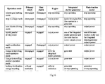
- the invention also provides a control method of a hybrid driving system based on the above described dual-clutch structure, the method at least comprising a neutral gear parking mode, a stop-to-charge mode, a rapid acceleration mode, a pure electric driving mode, a hybrid parallel driving mode, a charge-in-travelling series operation mode, a charge-in-travelling parallel operation mode and a braking deceleration energy recycling mode.
- the invention also provides a triple clutch structure hybrid driving system for vehicle which, on the basis of the dual-clutch hybrid driving system aforementioned, further comprises a second clutch, a second gear shaft, a third gear shaft and a second stage decelerating device, wherein a rotor support of the main traction motor is sequentially connected to the second gear shaft and a second stage driving gear of the second stage decelerating device via the second clutch, and the second stage driven gear is connected to a bridge gear of the first stage decelerating device via the third gear shaft.
- the invention also provides a control method of a hybrid driving system based on the above described triple clutch structure, the method at least comprising a neutral gear parking mode, a stop-to-charge mode, a rapid acceleration and gear shift mode, a pure electric driving and gear shift mode, a hybrid parallel driving and gear shift mode, a charge-in-travelling series operation and gear shift mode, a charge-in-travelling parallel operation and gear shift mode, and a braking deceleration energy recycling mode.
- the hybrid driving unit provided by the invention can be designed and manufactured as a separate working component of hybrid vehicle. For example, it can be provided to whole vehicle manufacturers as a separate component so as to realize integration.
- the hybrid driving system provided by the invention can realize a series/parallel power output of hybrid vehicle by properly taking advantage of power output by the engine and two motors, and can switch between different operation modes based on different road conditions and battery volumes so as to achieve energy saving and environment protection for hybrid vehicle and meet demands on system performances as required under different road conditions.
- the invention preferably employs a first clutch, a first gear shaft, a second clutch, a second gear shaft, a third gear shaft and a second stage decelerating device, etc., so that a proper connection of individual power sources is realized in a hybrid driving system.
- the power source of the main traction motor and transmission components of the hybrid electrical driving unit are connected in a proper and compact manner so as to realize a switch between connection and disconnection of individual hybrid sources and wheel and realize a shift of operation modes and gear positions of the hybrid driving system by shifting power-output torque.
- the triple clutch hybrid driving system provided by the invention is able to realize a continuous power gearshift function when shifting gear positions by controlling a synchronous disengagement/engagement of the first clutch and the second clutch.
- the design of this invention provides rooms to accommodate both clutches in between the cavity of each motor rotor support and main drive shaft. By doing so, the design can be more compact and thus left more space for other component interconnection usage.
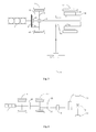
- Fig. 1 illustrates a principle view showing a driving system of a hybrid vehicle and connection relationship among components such as an electrical driving unit according to one particular embodiment of the invention
- Fig. 2 illustrates a schematic structure view of a dual-clutch hybrid driving system for vehicle provided by the invention and in accordance with a first embodiment of the invention
- Fig. 3 illustrates a mechanical structure view of the dual-clutch hybrid driving system for vehicle provided by the invention and in accordance with the first embodiment of the invention
- Fig. 4 illustrates a schematic structure view of a triple clutch hybrid driving system for vehicle provided by the invention and in accordance with a second embodiment of the invention
- Fig. 5 illustrates a mechanical structure view of the triple clutch hybrid driving system for vehicle provided by the invention and in accordance with the second embodiment of the invention
- Fig. 6 illustrates an operation mode table of the dual-clutch hybrid driving system for vehicle provided by the invention and in accordance with the first embodiment of the invention.
- Fig. 7 illustrates an operation mode table of the triple clutch hybrid driving system for vehicle provided by the invention and in accordance with the second embodiment of the invention.
- Fig. 1 illustrates a principle view showing a hybrid driving system and connection relationship among components such as an electrical driving unit according to one particular embodiment of the invention, i.e., showing connection manner of an engine, wheels, and an integrated starter-generator, a main traction motor, a differential and other various components of an electrical driving unit of a hybrid vehicle applied with a hybrid driving system provided by the invention, wherein the engine and the electrical driving unit constitute the hybrid driving system of the invention.
- the engine is connected to the electrical driving unit which outputs a hybrid power to the wheel via the differential.
- the specific connecting manner and operation mode will be discussed in detail in the following particular embodiments and a repeated description is omitted herein.
- gear box 1 could be a conventional mechanical gear box which is herein used as a component for realizing gear shift and power transmission in the electrical driving unit.
- the gear box can also be replaced by a mechanical structure which is able to realize the gear shift and power transmission functions without having an influence on the substantive content of the invention.
- a conventional vehicle typical consists of four basic portions, i.e., an engine, a chassis, a vehicle body and electrical equipments
- the hybrid driving system provided by the invention comprises three power sources of a hybrid vehicle (i.e., a main traction motor, an integrated starter-generator and an engine) and some structures of vehicle chassis and electrical equipments so as to realize some functions of engine, chassis and electrical equipments of the conventional vehicle, which are equivalent to power system, chassis and electrical equipments of a hybrid vehicle.
- a hybrid vehicle i.e., a main traction motor, an integrated starter-generator and an engine
- some structures of vehicle chassis and electrical equipments so as to realize some functions of engine, chassis and electrical equipments of the conventional vehicle, which are equivalent to power system, chassis and electrical equipments of a hybrid vehicle.
- those skilled in the art can make reference to other related power system, chassis, vehicle body and electrical equipments, etc. in the current existing technology so as to ensure that the hybrid driving system and corresponding electrical driving unit match with other components in order to
- the hybrid two-stage electrical driving unit provided by the invention also realize a gear shift among a neutral gear, a first gear and a second gear of hybrid vehicle, and enables the hybrid driving system to accommodate operation requirements under various road conditions without the need to match with an engine and main traction motor with high performance, making the hybrid vehicle better conform to practical requirements.
- the specific operation principle will be discussed in detail in first and second embodiments of the invention and a repeated description is thus omitted herein.
- the hybrid two-stage electrical driving unit provided by the invention can also realize a continuous power gear shift function by a control of the whole vehicle controller when performing gear position switch. It is the first time that this technology is applied to a hybrid vehicle. The application of this technology not only makes the hybrid driving system provided by the invention have a better energy saving effect, but also have a higher driving performance. The specific operation principle will be discussed in detail in the following second embodiment and a repeated description is thus omitted herein.
- Figs. 2 and 3 respectively illustrate a schematic structure view and a mechanical structure view of a dual-clutch hybrid driving system for vehicle provided by the invention and in accordance with a first embodiment of the invention wherein Fig. 2 only illustrates a brief connection relationship between various components of the driving system, and Fig. 3 illustrates a detailed mechanical connection manner of various components of the driving system.
- the hybrid driving system comprises a main shaft 8, a primary clutch 16, a first stage decelerating device 9, a main traction motor 17, an integrated starter-generator 4 and an engine 1, and further comprises a first clutch 15 and a first gear shaft 10.
- a driving disc 2 of the primary clutch 16 is connected to the engine 1 and a rotor support 41 of the integrated starter-generator 4; specifically, in this embodiment, a portion of the driving disc 2 that is near the center is directly connected to the engine 1, and accordingly, the driving disc 2 is connected to the rotor support 41 of the integrated starter-generator at its edge away from the center.
- a driven disc 3 of the primary clutch 16 is connected to one end of the main shaft 8 via a shock absorbing spring 19; specifically, in this embodiment, a center portion of the driven disc 3 is connected to the main shaft 8. An end of the main shaft 8 away from the primary clutch 16 is connected to a rotor support 14 of the main traction motor 17.
- the rotor support 14 of the main traction motor is connected to one end of the first gear shaft 10 via the first clutch 15, and the other end of the first gear shaft 10 is connected to a first stage driving gear of the first stage decelerating device 9.
- a first stage driven gear of the first stage decelerating device 9 is connected to a vehicle differential 7.
- the engine 1 and the integrated starter-generator 4 are connected to the driving disc 2 of the primary clutch 16 simultaneously.
- the engine 1 can output power to the integrated starter-generator 4
- the integrated starter-generator 4 can either generate electricity by using power output by the engine 1, or can output power together with the engine 1.
- the main shaft 8 is used to transmit power of each power source of the hybrid driving system.
- the hybrid driving system achieves power connection and disconnection between the engine 1 and the integrated starter-generator 4 and the main shaft 8 by controlling disengagement and engagement of the primary clutch 16.
- the driven disc 3 of the primary clutch 16 is connected to the main shaft 8 so that the hybrid driving system can control the engine 1 and the integrated starter-generator 4 to output mechanical power directly to the wheel 20 or not, by controlling disengagement and engagement of the primary clutch 16.
- the main shaft 8 is directly connected to the rotor support 14 of the main traction motor so that the power output by the engine 1 and the integrated starter-generator 4 can be transmitted to the rotor support 14 of the main traction motor so as to realize power coupling of three power sources of the hybrid driving system.
- a driving disc of the first clutch 15 is provided on the rotor support 14 of the main traction motor, and a driven disc of the first clutch 15 is provided on the first gear shaft 10 so that the hybrid driving system is connected to the first gear shaft 10 via the first clutch 15 and power is output outwardly through the first clutch 15, the first gear shaft 10, the first stage decelerating device 9 and the differential 7 in order to obtain a power transmission path of the hybrid driving system.
- the hybrid electrical driving unit for vehicle comprises the main traction motor 17, the integrated starter-generator 4, the differential 7, the main shaft 8, the first stage decelerating device 9, the primary clutch 16 and the first clutch 15, wherein the main shaft 8 is connected to the main traction motor 17, the driving disc 2 of the primary clutch 16 is connected to the integrated starter-generator 4 and vehicle engine 1, the driven disc 3 of the primary clutch 16 is connected to the main shaft 8, the main traction motor 17 is connected to the first stage decelerating device 9 via the first clutch 15, and the hybrid electrical driving unit outputs power via the first stage decelerating device 9.
- connection manner of the electrical driving unit can be conducted with reference to the hybrid driving system described in this embodiment and redundant description is omitted herein.
- the hybrid driving unit can be designed and manufactured as a separate operation component of the hybrid vehicle. For example, it can be supplied to whole vehicle manufacturer as a separate component so as to realize a technical effect of integration.
- the main shaft 8 and the first gear shaft 10 are arranged coaxially in the hybrid driving system.
- the first gear shaft 10 is provided in the periphery of the main shaft 8 as a hollow shaft.
- the driven disc 3 of the primary clutch 16 is preferably connected to one end of the main shaft 8 via the shock absorbing spring 19.
- the driven disc 3 of the primary clutch 16 can also be connected to the main shaft 8 via other elastic devices as long as the technical objective of shock absorbing can be achieved. Redundant description thereof is also omitted.
- the hybrid driving system provided by the invention outputs power via the first stage decelerating device 9.
- the first stage decelerating device 9 comprises a first stage driving gear and a first stage driven gear.
- the first stage driving gear of the first stage decelerating device 9 is provided on the first gear shaft 10.
- the first stage decelerating device 9 may further comprise a bridge gear, i.e., the first stage driving gear and the first stage driven gear can intermesh with each other via a gear ring of the bridge gear as required so as to vary speed difference output and center distance of the main shaft 8.
- the first stage driving gear of the first stage decelerating device 9 is connected to one end of the first gear shaft 10; in an direction perpendicular to the main shaft 8, the first stage driving gear intermeshes with the bridge gear and the bridge gear intermeshes with the first stage driven gear, which is in turn connected to a housing of the differential 7.
- the hybrid driving system outputs power to the first stage decelerating device 9 via the first gear shaft 10, at which time the speed reduction ratio of the first stage decelerating device 9 is equivalent to tooth number ratio of the first stage driven gear and the first stage driving gear, thus realizing increase of fin*al output torque of the hybrid driving system.
- the primary clutch 16 is provided in a space formed by the rotor support 41 of the integrated starter-generator and the main shaft 8.
- the driving disc 2 of the primary clutch 16 is provided in the space on one side adjacent to the engine 1 and is connected to the rotor support 41 of the integrated starter-generator, and the driven disc 3 of the primary clutch 16 is provided in the space on one side adjacent to the main shaft 8.
- the primary clutch 16 in this embodiment can be arranged without increasing volume of the hybrid driving system provided by the invention and altering the arrangement of other components of the hybrid driving system, which makes full use of space inside the hybrid driving system so that the design of hybrid driving system is made more compact.
- the driven disc 3 of the primary clutch 16 is arranged inside a connecting mechanism between the driving disc 2 of the primary clutch 16 and the integrated starter-generator 4. Redundant description thereof is also omitted.
- the flywheel i.e., the moments of inertia of the rotor 42 and rotor support 41 of the integrated starter-generator and the driving disc 2 of the primary clutch 16 are designed to be equivalent to a conventional engine flywheel so that a conventional engine flywheel can be cancelled.
- This design of the invention enables a vehicle applied with the invention to cancel engine flywheel, thus making the connection between the hybrid electrical driving unit and the engine more compact.
- the first clutch 15 is provided in a space formed by the rotor support 14 of the main traction motor and the main shaft 8. Specifically, with reference to Fig. 3 , the first clutch 15 is provided at a side adjacent to the primary clutch 16 in the space formed by the rotor support 14 of the main traction motor and the main shaft 8, the driving disc of the first clutch 15 is connected to the rotor support 14 of the main traction motor, and the driven disc of the first clutch 15 is connected to one end of the first gear shaft 10.
- the first clutch 15 in this embodiment can be arranged without increasing volume of the hybrid driving system provided by the invention and altering the arrangement of other components of the hybrid driving system, which makes full use of space inside the hybrid driving system so that the design of hybrid driving system is made more compact.
- the first clutch 15 can also be arranged or connected in other ways as long as the control to power output of the hybrid driving system can be realized. Redundant description thereof is also omitted.
- Fig. 6 illustrates an operation mode table of the dual-clutch hybrid driving system for vehicle provided by the invention and in accordance with the first embodiment of the invention.
- a switch between different operation states of the hybrid driving system can be realized by using a clutch control system to control disengagement and engagement of the first clutch 15, and the hybrid driving system for vehicle realizes power disconnection and connection between the hybrid driving system and the wheel 20 by disengagement and engagement of the first clutch 15.
- a hybrid whole vehicle control system for vehicle performs control to the engine 1, the integrated starter-generator 4 and the main traction motor 17 on basis of requirements on driver's accelerator/brake pedal input so as to realize various operation modes for the hybrid vehicle.
- the embodiment at least on basis of the architecture of the hybrid driving system for vehicle shown in Fig.
- the main traction motor 17 can be at least provided with a neutral gear parking mode, a stop-to-charge mode, a rapid acceleration mode, a pure electric driving mode, a hybrid parallel driving mode, a charge-in-travelling series operation mode, a charge-in-travelling parallel operation mode and a braking deceleration energy recycling mode, etc.
- the hybrid driving system for realizing the afore-mentioned control modes comprises the main shaft 8, the primary clutch 16, the first stage decelerating device 9, the main traction motor 17, the integrated starter-generator 4 and the engine 1, and further comprises the first clutch 15 and the first gear shaft 10 for realizing cease and activation of hybrid power output according to the invention.
- the driving disc 2 of the primary clutch 16 is connected to the engine 1 and the rotor support 41 of the integrated starter-generator, and the driven disc 3 of the primary clutch 16 is connected to one end of the main shaft 8 via the shock absorbing spring 19; one end of the main shaft 8 which is away from the primary clutch 16 is connected to the rotor support 14 of the main traction motor, and the rotor support 14 of the main traction motor is sequentially connected to the first gear shaft 10 and the first stage driving gear of the first stage decelerating device 9 via the first clutch 15, and the first stage driven gear is connected to the differential 7.
- the three power sources of the hybrid driving system for vehicle i.e., the engine 1, the main traction motor 17 and the integrated starter-generator 4 are disconnected from the wheel 20 in power transmission.
- the primary clutch 16 and the first clutch 15 are controlled to be disengaged, and the engine 1, the main traction motor 17 and the integrated starter-generator 4 are controlled to stop operating.
- the integrated starter-generator 4 When a vehicle applied with the hybrid driving system for vehicle is in the stop-to-charge mode, the integrated starter-generator 4 charges a battery pack of the hybrid vehicle by making use of power output by the engine 1 when the vehicle is stopped. In this mode, the primary clutch 16 and the first clutch 15 are controlled to be disengaged, the whole vehicle controller of the hybrid vehicle controls the integrated starter-generator 4 to firstly enter an activation mode so as to perform ignition operation on the engine 1; then the integrated starter-generator 4 enters an electricity generating operation mode so as to charge the battery pack, and the main traction motor 17 does not operate.
- the hybrid driving system uses power collectively output by the engine 1, the integrated starter-generator 4 and the main traction motor 17 to drive the vehicle in running.
- the engine 1, the main traction motor 17 and the integrated starter-generator 4 are controlled to output power, and the primary clutch 16 and the first clutch 15 are controlled to be engaged.
- the engine 1, the main traction motor 17 and the integrated starter-generator 4 collectively output power to drive the vehicle so as to maximize output power of the hybrid driving system.
- the hybrid driving system drives the vehicle in running by using power output by the main traction motor 17.
- the main traction motor 17 is controlled to output power
- the engine 1 and the integrated starter-generator 4 are controlled to stop operating
- the primary clutch 16 is controlled to be disengaged
- the first clutch 15 is controlled to be engaged.
- the hybrid driving system drives the vehicle in running by using power output by the engine 1 and the main traction motor 17 or the integrated starter-generator 4.
- the engine 1 and one of the main traction motor 17 and the integrated starter-generator 4 (which is judged by the whole vehicle controller according to total efficiency) are controlled to perform power output, and the primary clutch 16 and the first clutch 15 are controlled to be engaged.
- the engine 1 and one of the main traction motor 17 and the integrated starter-generator 4 collectively drive the vehicle, and the hybrid driving system outputs power from the engine 1 and one of the main traction motor 17 and the integrated starter-generator 4 to the wheel 20.
- the hybrid driving system When a vehicle applied with the hybrid driving system for vehicle is in the charge-in-travelling series mode, the hybrid driving system charges a battery pack of the hybrid vehicle by using power output by the engine 1, and drives the vehicle by using power output by the main traction motor 17.
- the engine 1 is controlled to drive the integrated starter-generator 4 to perform electricity generating operation
- the main traction motor 17 is controlled to perform power output operation
- the first clutch 15 is controlled to be engaged
- the primary clutch 16 is controlled to be disengaged.
- the primary clutch 16 cannot be engaged due to limitations of mechanical speed ratio and the lowest operation speed of the engine 1
- the main traction motor 17 drives the vehicle
- the integrated starter-generator 4 enters an electricity generating mode
- the electric energy required for the main traction motor 17 is provided by the integrated starter-generator 4
- the insufficient part is provided by the battery pack or the residual part is absorbed by the battery pack
- the hybrid driving system outputs power from the main traction motor 17 to the wheel 20 via a main decelerator.
- the hybrid driving system drives the vehicle in running by using power output by the engine 1 and the main traction motor 17, and simultaneously charges the battery pack of the hybrid vehicle by using the integrated starter-generator 4 to generate electricity.
- the engine 1 and the main traction motor 17 are controlled to output power
- the integrated starter-generator 4 is controlled to perform electricity generating operation
- the primary clutch 16 and the first clutch 15 are controlled to be engaged.
- the power portion of the engine 1 and the main traction motor 17 directly take part in driving together, and the other portions are used by the integrated starter-generator 4 to generate electricity so as to charge battery.
- a motor controller of the hybrid driving system controls the main traction motor 17 and/or the integrated starter-generator 4 to recycle energy via the first stage decelerating device 9 when the vehicle is braking and charge the battery pack.
- Figs. 4 and 5 respectively illustrate a schematic structure view and a mechanical structure view of a triple clutch hybrid driving system for vehicle provided by the invention and in accordance with a second embodiment of the invention wherein Fig. 4 only illustrates a brief connection relationship between various components of the driving system, and Fig. 5 illustrates a detailed mechanical connection manner of various components of the driving system.
- the embodiment will be described hereinafter by taking Fig.
- the hybrid driving system comprises a main shaft 8, a primary clutch 16, a first stage decelerating device 9, a main traction motor 17, an integrated starter-generator 4 and an engine 1, and the hybrid driving system further comprises a first clutch 15, a first gear shaft 10, a second clutch 12, a second gear shaft 11, a third gear shaft 6 and a second stage decelerating device 5.
- a driving disc 2 of the primary clutch 16 is connected to the engine 1 and a rotor support 41 of the integrated starter-generator; specifically, in this embodiment, a portion of the driving disc 2 that is near the center is directly connected to the engine 1, and accordingly, the driving disc 2 of the primary clutch 16 is connected to the rotor support 41 of the integrated starter-generator at its edge away from the center.
- a driven disc 3 of the primary clutch 16 is connected to one end of the main shaft 8; specifically, in this embodiment, a center portion of the driven disc 3 is connected to the main shaft 8.
- An end of the main shaft 8 away from the primary clutch 16 is connected to a rotor support 14 of the main traction motor.
- the rotor support 14 of the main traction motor is connected to one end of the first gear shaft 10 via the first clutch 15, and the other end of the first gear shaft 10 is connected to a first stage driving gear of the first stage decelerating device 9.
- the rotor support 14 of the main traction motor is connected to one end of the second gear shaft 11 via the second clutch 12, the other end of the second gear shaft 11 is connected to a second stage driving gear of the second stage decelerating device 5, and a second stage driven gear of the second stage decelerating device 5 is connected to a bridge gear of the first stage decelerating device 9 via the third gear shaft 6.
- the first stage driven gear is connected to a differential 7.
- the engine 1 and the integrated starter-generator 4 are connected to the driving disc 2 of the primary clutch 16 simultaneously.
- the engine 1 can output power to the integrated starter-generator 4
- the integrated starter-generator 4 can either generate electricity by using power output by the engine 1, or can output power together with the engine 1.
- the main shaft 8 is used to transmit power of each power source of the hybrid driving system.
- the hybrid driving system achieves power connection and disconnection between the engine 1 and the integrated starter-generator 4 and the main shaft 8 by controlling disengagement and engagement of the primary clutch 16.
- the driven disc 3 of the primary clutch 16 is connected to the main shaft 8 so that the hybrid driving system can control the engine 1 and the integrated starter-generator 4 to output mechanical power directly to the wheel 20 or not, by controlling disengagement and engagement of the primary clutch 16.
- the main shaft 8 is directly connected to the rotor support 14 of the main traction motor so that the power output by the engine 1 and the integrated starter-generator 4 can be transmitted to the rotor support 14 of the main traction motor so as to realize power coupling of three power sources of the hybrid driving system.
- the hybrid driving system realizes controls of stop, activation and gear position switch of power output of the hybrid driving system by controlling the first clutch 15 and the second clutch 12.
- a driving disc of the second clutch 12 is provided on the rotor support 14 of the main traction motor so that the hybrid driving system can be connected to the second gear shaft 11 via a driven disc of the second clutch 12 and power is output outwardly through the second clutch 12, the second gear shaft 11, the second stage decelerating device 5, the third gear shaft 6, the first stage decelerating device 9 and the differential 7 in order to obtain a power transmission path for a first gear (low speed gear) of the hybrid driving system;
- a driving disc of the first clutch 15 is provided on the rotor support 14 of the main traction motor so that the hybrid driving system is connected to the first gear shaft 10 via a driven disc of the first clutch 15 and power is output outwardly through the first clutch 15, the first gear shaft 10, the first stage decelerating device 9 and the differential 7 in order to obtain a power transmission path for a second gear (high speed gear) of the hybrid driving system.
- the hybrid electrical driving unit comprises the main traction motor 17, the integrated starter-generator 4, the differential 7, the main shaft 8, the first stage decelerating device 9, the primary clutch 16, the first clutch 15, the second clutch 12 and the second stage decelerating device 5, wherein the main shaft 8 is connected to the main traction motor 17, the driving disc 2 of the primary clutch 16 is connected to the integrated starter-generator 4 and the vehicle engine 1, the driven disc 3 of the primary clutch 16 is connected to the main shaft 8, the hybrid electrical driving unit outputs power via the first stage decelerating device 9, the main traction motor 17 is connected to the first stage decelerating device 9 via the first clutch 15, the main traction motor 17 is connected to the second stage decelerating device 5 via the second clutch 12 and is then connected to the first stage decelerating device 9 via the second stage decelerating device 5.
- connection manner of the electrical driving unit can be conducted with reference to the hybrid driving system described in this embodiment and redundant description is omitted herein.
- the hybrid driving unit according to this embodiment can be designed and manufactured as a separate operation component of the hybrid vehicle. For example, it can be supplied to the whole vehicle manufacturer as a separate component so as to realize a technical effect of integration.
- the power output when the hybrid driving system operates in the first gear mode, the power output will be decelerated by the second stage decelerating device 5 and the first second stage decelerating device 9 and then output; the output power has a large torque and small rotational speed, thus meeting operation requirements under such conditions as when the vehicle is starting, climbing and rapidly accelerating; whereas when the hybrid driving system operates in the second gear mode, the power output will be decelerated by the first second stage decelerating device 9 and then output; the output power has a small torque and large rotational speed, thus meeting operation requirements under such conditions as when the vehicle is running at intermediate and high speeds.
- the specific operation manner and control mode will be described in detail hereinafter and redundant description is omitted herein.
- the choice between two gear positions according to the hybrid driving system for vehicle provided by the invention enables requirements on torque output and high speed running for hybrid vehicle to be met even when the requirements on the main traction motor 17 is properly lowered, and enables the range of operation conditions suitable for parallel driving operation of hybrid vehicle to be enlarged; meanwhile, the operation efficiency of the main traction motor 17 is further optimized.
- the primary clutch 16 is provided in a space formed by the rotor support 41 of the integrated starter-generator and the main shaft 8.
- the driving disc 2 of the primary clutch 16 is provided in the space on one side adjacent to the engine 1 and is connected to the rotor support 41 of the integrated starter-generator, and the driven disc 3 of the primary clutch 16 is provided in the space on one side adjacent to the main shaft 8.
- the arrangement and technical effect of the primary clutch 16 can refer to the embodiment shown in above Figs. 2 and 3 , and redundant description is omitted herein.
- the moments of inertia of the rotor 42 and the rotor support 41 of integrated starter-generator and the driving disc 2 of the primary clutch 16 can be designed to be an equivalent to a conventional engine flywheel so that the conventional engine flywheel can be cancelled.
- the arrangement thereof can refer to the embodiment shown in above Figs. 2 and 3 , and redundant description is omitted herein.
- the first clutch 15 and the second clutch 12 are provided in a space formed by the rotor support 14 of the main traction motor and the main shaft 8.
- the driving disc of the first clutch 15 is connected to the rotor support 14 of the main traction motor, and the driven disc of the first clutch 15 is connected to one end of the first gear shaft 10;
- the driving disc of the second clutch 12 is connected to the rotor support 14 of the main traction motor, and the driven disc of the second clutch 12 is connected to one end of the second gear shaft 11.
- first clutch 15 and the second clutch 12 in this embodiment can be arranged without increasing volume of the hybrid driving system provided by the invention and altering the arrangement of other components of the hybrid driving system, which makes full use of space inside the hybrid driving system so that the design of hybrid driving system is made more compact.
- the main shaft 8, the first gear shaft 10 and the second gear shaft 11 are arranged coaxially in the hybrid driving system.
- the second gear shaft 11 and the first gear shaft 10 are sequentially provided in the periphery of the main shaft 8 as hollow shafts, which does not have an influence on substantive content of the invention and redundant description is therefore omitted.
- the driven disc 3 of the primary clutch 16 is preferably connected to one end of the main shaft 8 via the shock absorbing spring 19.
- the driven disc 3 of the primary clutch 16 can also be connected to the main shaft 8 via other elastic devices as long as the technical objective of shock absorbing can be achieved. Redundant description thereof is also omitted.
- the hybrid driving system provided by the invention outputs power via the first stage decelerating device 9.
- the first stage driving gear of the first stage decelerating device 9 is provided on the first gear shaft 10
- the second stage driving gear of the second stage decelerating device 5 is provided on the second gear shaft 11.
- the first stage decelerating device 9 comprises a first stage driving gear, a first stage driven gear and a bridge gear, i.e., the first stage driving gear and the first stage driven gear are preferably intermeshed via a gear ring of the bridge gear as required so as to vary speed difference output and center distance of the main shaft 8, wherein the first stage driving gear of the first stage decelerating device 9 is connected to one end of the first gear shaft 10, and in a direction perpendicular to the main shaft 8, the first stage driving gear intermeshes with the bridge gear and the bridge gear intermeshes with the first stage driven gear, which is in turn connected to a housing of the differential 7.
- the second stage decelerating device 5 comprises a second stage driving gear and a second stage driven gear.
- the second stage driving gear of the second stage decelerating device 5 is connected to one end of the second gear shaft 11, and intermeshes with the second stage driven gear in a direction perpendicular to the main shaft 8, the second stage driven gear is connected to one end of the third gear shaft 6, and the other end of the third gear shaft 6 is connected to the bridge gear of the first stage decelerating device 9.
- the third gear shaft 6 is arranged in parallel with the main shaft 8, which facilitates the arrangement of gear shafts inside the hybrid driving system provided by the invention and corresponding hybrid two stage electrical driving unit.
- the hybrid driving system When the first clutch 15 is engaged, at this time the second clutch 12 is disengaged, the hybrid driving system outputs power to the first stage decelerating device 9 via the first gear shaft 10. At this moment, the speed reduction ratio of the first stage decelerating device 9 is the tooth number ratio of the first stage driven gear and the first stage driving gear, thus realizing deceleration at the second gear of the hybrid driving system and increase of output torque; when the second clutch 12 is engaged, at this time the first clutch 15 is disengaged, the hybrid driving system outputs power to the second stage decelerating device 5 and the first stage decelerating device 9 via the second gear shaft 11.
- the speed reduction ratio of the second stage decelerating device 5 and the first stage decelerating device 9 is the product of the tooth number ratio of the second stage driven gear and the second stage driving gear and the tooth number ratio of the first stage driven gear and the bridge gear, thus realizing deceleration at the first gear of the hybrid driving system and increase of output torque.
- the whole vehicle controller of the hybrid vehicle can also realize the application of a continuous power shift function in a hybrid vehicle by controlling a synchronous disengagement/engagement of the first and second clutch 12 control mechanism, thereby ensuring a synchronous disengagement/engagement control of the first clutch 15 and the second clutch 12 during gear shift.
- both the powers from two output shafts (i.e., the first gear shaft 10 and the second gear shaft 11) of the invention will be linked together with the final output shaft of the electrical driving unit so as to transmit power to the wheel 20.
- the whole vehicle controller controls the first clutch 15 and the second clutch 12 simultaneously so that when one of the first clutch 15 and the second clutch 12 performs disengagement, the other one performs engagement simultaneously, thus ensuring the power output from the hybrid driving system can always be output to the wheel 20 via the first clutch 15 or the second clutch 12 so as to realize a continuous power shift function.
- the specific implementations thereof can be conducted with reference to other patent documents or current existing technology and are not described in detail herein.
- first clutch 15 and the second clutch 12 provided by this embodiment are used in the form of a collocation of dry clutch or wet clutch, i.e., the first clutch 15 can be a dry clutch or a wet clutch, and the second clutch 12 can also be a dry clutch or a wet clutch.
- both the first clutch 15 and the second clutch 12 are dry clutches.
- one of the first clutch 15 and the second clutch 12 is a dry clutch and the other is a wet clutch; more specifically, when the vehicle is designed to mainly run at intermediate and high speeds, the first clutch 15 is a dry clutch, and when the vehicle is designed to mainly run at intermediate and low speeds, the second clutch 12 is a dry clutch. Even less preferably, in particular in case where the inner space is not sufficient to place one dry clutch and one wet clutch, both the first clutch 15 and the second clutch 12 are wet clutches.
- the first clutch shown in Fig. 2 or 3 can also be a dry clutch or a wet clutch, for example preferably a dry clutch. Redundant description thereof is omitted herein.
- Fig. 7 illustrates an operation mode table of the triple clutch hybrid driving system for vehicle provided by the invention and in accordance with the second embodiment of the invention.
- the clutch control system can realize a switch among different operation states of the hybrid driving system by controlling disengagement/engagement of the first clutch 15 and the second clutch 12, and the hybrid driving system for vehicle realizes power disconnection and connection between the hybrid driving system and the wheel 20 as well as gear position switch by disengagement/engagement of the first clutch 15 and the second clutch 12.
- the hybrid driving system can output power to the wheel 20; when the first clutch 15 and the second clutch 12 are disengaged, the hybrid driving system can not output power to the wheel 20; and when the hybrid driving system is shifting gears, the hybrid driving system can vary power-output torque.
- the hybrid whole vehicle control system for vehicle performs controls to the engine 1, the integrated starter-generator 4 and the main traction motor 17 on basis of requirements on driver's accelerator/brake pedal input and can optimally select high efficient power source on basis of requirement on driver's power so as to realize various operation modes for the hybrid vehicle.
- the main traction motor 17 can be at least provided with a neutral gear parking mode, a stop-to-charge mode, a rapid acceleration and gear shift mode, a pure electric driving and gear shift mode, a hybrid parallel driving and gear shift mode, a charge-in-travelling series operation and gear shift mode, a charge-in-travelling parallel operation and gear shift mode, and a braking deceleration energy recycling mode, etc.
- the hybrid driving system for realizing the afore-mentioned control modes comprises the main shaft 8, the primary clutch 16, the first stage decelerating device 9, the main traction motor 17, the integrated starter-generator 4 and the engine 1, and further comprises the first clutch 15, the first gear shaft 10, the second clutch 12, the second gear shaft 11, the third gear shaft 6 and the second decelerating device 5 for realizing cease and activation of hybrid power output as well as gear position switch according to the invention.
- the driving disc 2 of the primary clutch 16 is connected to the engine 1 and the rotor support 41 of the integrated starter-generator, and the driven disc 3 of the primary clutch 16 is connected to one end of the main shaft 8 via the shock absorbing spring 19; one end of the main shaft 8 which is away from the primary clutch 16 is connected to the rotor support 14 of the main traction motor, the rotor support 14 of the main traction motor is sequentially connected to the first gear shaft 10 and the first stage driving gear of the first stage decelerating device 9 via the first clutch 15, the rotor support 14 of the main traction motor is sequentially connected to the second gear shaft 11 and the second stage driving gear of the second stage decelerating device 5 via the second clutch 12, the second stage driven gear is connected to the bridge gear of the first stage decelerating device 9 via the third gear shaft 6, and the first stage driven gear is connected to the differential 7.
- the triple clutch hybrid driving system for vehicle provided by this embodiment can realize a continuous power shift function when switching gear positions in each mode, thus ensuring a synchronous disengagement/engagement control of the first clutch 15 and the second clutch 12 during gear shift.
- the specific control manner thereof can be conducted with reference to the second particular embodiment described above, and redundant description thereof is thus omitted.
- the three power sources of the hybrid driving system for vehicle i.e., the engine 1, the main traction motor 17 and the integrated starter-generator 4 are disconnected from the wheel 20 in power transmission.
- the primary clutch 16, the first clutch 15 and the second clutch 12 are controlled to be disengaged, and the engine 1, the main traction motor 17 and the integrated starter-generator 4 are controlled to stop operating.
- the integrated starter-generator 4 When a vehicle applied with the hybrid driving system for vehicle is in the stop-to-charge mode, the integrated starter-generator 4 charges the battery pack of the hybrid vehicle by making use of power output by the engine 1 when the vehicle is stopped.
- the primary clutch 16, the first clutch 15 and the second clutch 12 are controlled to be disengaged, the whole vehicle controller of the vehicle controls the integrated starter-generator 4 to firstly enter an activation mode so as to perform ignition operation on the engine 1; then the integrated starter-generator 4 enters an electricity generating operation mode so as to charge the battery pack, and the main traction motor 17 does not operate.
- the whole vehicle controller detects that the battery volume is overly low, e.g. when the vehicle is stopped for a long time period and the air conditioner is in the operation state, will it be necessary to enter the stop-to-charge mode.
- the hybrid driving system uses power output by the engine 1, the integrated starter-generator 4 and the main traction motor 17 to collectively drive the vehicle in running and perform gear shift function.
- the engine 1, the main traction motor 17 and the integrated starter-generator 4 are controlled to output power
- the primary clutch 16 and the second clutch 12 are controlled to be engaged and the first clutch 15 is controlled to be disengaged so as to achieve the first gear function in this mode
- the primary clutch 16 and the first clutch 15 are controlled to be engaged and the second clutch 12 is controlled to be disengaged so as to achieve the second gear function in this mode.
- the hybrid driving system drives the vehicle in running by using power output by the main traction motor 17 and performs gear shift.
- the main traction motor 17 is controlled to output power
- the engine 1 and the integrated starter-generator 4 are controlled to stop operating
- the primary clutch 16 and the first clutch 15 are controlled to be disengaged and the second clutch 12 is controlled to be engaged so as to achieve the first gear function in this mode
- the primary clutch 16 and the second clutch 12 are controlled to be disengaged and the first clutch 15 is controlled to be engaged so as to achieve the second gear function in this mode.
- the main traction motor 17 will drive the vehicle alone, the battery pack provides electricity energy to the main traction motor 17, and the hybrid driving system outputs the power output by the main traction motor 17 to the wheel 20.
- the hybrid driving system drives the vehicle in running by using power output by the engine 1 and the main traction motor 17 or the integrated starter-generator 4 and performs gear shift.
- the engine 1 and one of the main traction motor 17 and the integrated starter-generator 4 (which is judged by the whole vehicle controller according to total efficiency) are controlled to perform power output operation, the primary clutch 16 and the second clutch 12 are controlled to be engaged and the first clutch 15 is controlled to be disengaged so as to achieve the first gear function in this mode, and the primary clutch 16 and the first clutch 15 are controlled to be engaged and the second clutch 12 is controlled to be disengaged so as to achieve the second gear function in this mode.
- the engine 1 and one of the main traction motor 17 and the integrated starter-generator 4 collectively drive the vehicle, and the hybrid driving system outputs power from the engine 1 and one of the main traction motor 17 and the integrated starter-generator 4 to the wheel 20.
- the hybrid driving system charges the battery pack of the hybrid vehicle by using power output by the engine 1, and drives the vehicle in running by using power output by the main traction motor 17 and performs gear shift.
- the engine 1 is controlled to drive the integrated starter-generator 4 to perform electricity generating operation
- the main traction motor 17 is controlled to perform power output operation
- the second clutch 12 is controlled to be engaged and the primary clutch 16 and the first clutch 15 are controlled to be disengaged so as to achieve the first gear function in this mode
- the first clutch 15 is controlled to be engaged and the primary clutch 16 and the second clutch 12 are controlled to be disengaged so as to achieve the second gear function in this mode.
- the primary clutch 16 cannot be engaged due to limitations of mechanical speed ratio and the lowest operation speed of the engine 1
- the main traction motor 17 drives the vehicle
- the integrated starter-generator 4 enters an electricity generating mode
- the electric energy required for the main traction motor 17 is provided by the integrated starter-generator 4
- the insufficient part is provided by the battery pack or the residual part is absorbed by the battery pack
- the hybrid driving system outputs power from the main traction motor 17 to the wheel 20.
- the hybrid driving system drives the vehicle in running by using power output by the engine 1 and the main traction motor 17, and simultaneously charges the battery pack of the hybrid vehicle by using the integrated starter-generator 4 to generate electricity, and performs gear shift.
- the engine 1 and the main traction motor 17 are controlled to output power
- the integrated starter-generator 4 is controlled to perform electricity generating operation
- the primary clutch 16 and the second clutch 12 are controlled to be engaged and the first clutch 15 is controlled to be disengaged so as to achieve the first gear function in this mode
- the primary clutch 16 and the first clutch 15 are controlled to be engaged and the second clutch 12 is controlled to be disengaged so as to achieve the second gear function in this mode.
- the power portion of the engine 1 and the main traction motor 17 directly take part in driving together, and the other portions are used by the integrated starter-generator 4 to generate electricity so as to charge the battery.
- a motor controller of the hybrid driving system controls the main traction motor 17 and/or the integrated starter-generator 4 to perform energy recycling when the vehicle is braking and charge the battery pack.
Abstract
Description
- The invention relates to hybrid vehicle, especially the plug-in hybrid vehicle (PHEV) drive and shifting arrangement. In more specifically, it related to the hybrid power train that is driven by dual e-motors equipped with multi-clutch system and the associated electric controlled system to perform the multiple stage shifting function, along with the corresponding optimal control method.
- Energy saving and environmental protection have become the main focus in current automobile industry for new vehicle development. With this respective, the hybrid vehicle has turned into a main core technology and pursued by many automobile manufactures globally. Wherein, except the pure e-drive, the PHEV is one of the most fuel saving solutions, it has being advocated by many major automobile manufacturers. The PHEV primary consists of a relative lower displacement engine and one or two motors. Under normal vehicle running, the motor is generally responsible for providing pure electric power output and braking recycling energy at intermediate and low speeds, it also is used to achieve engine starting, while the engine can generate electricity by turning the motor when necessary, or take part in or boost power driving.
- In current technology, the engine and the motor in the above-described plug-in type hybrid driving system are coupled mostly by the following ways:
- I. Series solution: Such as GM Volt hybrid concept, it is a typical PHEV, The battery in the hybrid driving system can be charged by using the outlet of household power supply (e.g. 110V/220V). The PHEV can provid a longer pure electrically-driven travelling distance than a full hybrid electric vehicle. While when the battery power is dropping at a low level, the engine will automatically start to generate electricity through motor for battery charge to provide powe, but the engine in this model does not take part in vehicle running operation directly. Under the long distance travelling condition, it required to convert mechanical (engine) energy into electric energy (thru motor/generator then store in battery), and then re-converting the electric energy into mechanical (driving motor) energy for power output. Therefore, the operational efficiency by the engine power is relative lower. Besides, in order to ensure acceleration/climbing performance of the vehicle, the demands on main traction motor and battery power are higher than the normal running condition, thus boosts higher cost on vehicle.
- II. Parallel solution: Such as VW Phaeton GP2 hybrid vehicle. It is a driving-generating integrated machine, applying two clutches to connect the engine and conventional gear box. This hybrid vehicle design is simple in structure with lower cost. However, it can only be adapted to a large vehicle or rear driving vehicle, because the requirements on spatial dimensions of driving system inside the vehicle are high. Besides, the output power of the driving-generating integrated machine is generally not large enough, making it difficult to ensure the driving performance of the vehicle, when it is extensively driven by the pure electric drive mode.
- III. Series-parallel Power Split solution: Such as Toyota Hybrid System (referring to
CN patent application No. 200480019795.5 CN patent application No. 200480038070.0 - F3DM type hybrid vehicle: This is another example, the vehicle is launched by BYD Holding Ltd.. Using a relatively simple connection manner (referring to
CN patent application No. 200610141069.1 - In viewing of the deficiencies of the current existing technology, the objective of the invention is to provide a series/parallel dual motor multi-clutch hybrid electrical driving unit for vehicle as well as a corresponding driving system and driving control method by making the improvement on the structure and connection arrangement of hybrid driving system.
- According to one aspect of the invention, the invention provides a dual-clutch hybrid electrical driving unit for vehicle comprising a main traction motor, an integrated starter-generator, a differential, a main shaft, a first stage decelerating device and a primary clutch, wherein the main shaft is connected to the main traction motor, a driving disc of the primary clutch is connected to the integrated starter-generator and an engine of vehicle, a driven disc of the primary clutch is connected to the main shaft, and the hybrid electrical driving unit outputs power via the first stage decelerating device, characterized in that the hybrid electrical driving unit further comprises a first clutch, and the main traction motor is connected to the first stage decelerating device via the first clutch.
- According to another aspect of the invention, the invention also provides a triple clutch hybrid electrical driving unit for vehicle which is based on the dual-clutch hybrid electrical driving unit concept described in the above paragraph, and further comprises a second clutch and a second stage decelerating device, wherein the main traction motor is connected to the second stage decelerating device via the second clutch, and is further connected to the first stage decelerating device via the second stage decelerating device.
- According to one aspect of the invention, the invention provides a dual-clutch hybrid driving system for vehicle comprising a main shaft, a primary clutch, a first stage decelerating device, a main traction motor, an integrated starter-generator and an engine, wherein the hybrid driving system further comprises a first clutch and a first gear shaft, a driving disc of the primary clutch of the hybrid driving system is connected to the engine and a rotor support of the integrated starter-generator, a driven disc of the primary clutch is connected to one end of the main shaft, an end of the main shaft which is away from the primary clutch is connected to a rotor support of the main traction motor, the rotor support of the main traction motor is sequentially connected to the first gear shaft and a first stage driving gear of the first stage decelerating device via the first clutch, and the first stage driven gear is connected to a differential of vehicle.
- According to still another aspect of the invention, the invention also provides a control method of a hybrid driving system based on the above described dual-clutch structure, the method at least comprising a neutral gear parking mode, a stop-to-charge mode, a rapid acceleration mode, a pure electric driving mode, a hybrid parallel driving mode, a charge-in-travelling series operation mode, a charge-in-travelling parallel operation mode and a braking deceleration energy recycling mode.
- According to another aspect of the invention, the invention also provides a triple clutch structure hybrid driving system for vehicle which, on the basis of the dual-clutch hybrid driving system aforementioned, further comprises a second clutch, a second gear shaft, a third gear shaft and a second stage decelerating device, wherein a rotor support of the main traction motor is sequentially connected to the second gear shaft and a second stage driving gear of the second stage decelerating device via the second clutch, and the second stage driven gear is connected to a bridge gear of the first stage decelerating device via the third gear shaft.
- According to still another aspect of the invention, the invention also provides a control method of a hybrid driving system based on the above described triple clutch structure, the method at least comprising a neutral gear parking mode, a stop-to-charge mode, a rapid acceleration and gear shift mode, a pure electric driving and gear shift mode, a hybrid parallel driving and gear shift mode, a charge-in-travelling series operation and gear shift mode, a charge-in-travelling parallel operation and gear shift mode, and a braking deceleration energy recycling mode.
- The hybrid driving unit provided by the invention can be designed and manufactured as a separate working component of hybrid vehicle. For example, it can be provided to whole vehicle manufacturers as a separate component so as to realize integration.
- By a simple and effective design, the hybrid driving system provided by the invention can realize a series/parallel power output of hybrid vehicle by properly taking advantage of power output by the engine and two motors, and can switch between different operation modes based on different road conditions and battery volumes so as to achieve energy saving and environment protection for hybrid vehicle and meet demands on system performances as required under different road conditions. At least on the basis of a hybrid driving system provided in the current existing technology which consists of a main shaft, a primary clutch, a first stage decelerating device, a main traction motor, an integrated starter-generator and an engine, etc., the invention preferably employs a first clutch, a first gear shaft, a second clutch, a second gear shaft, a third gear shaft and a second stage decelerating device, etc., so that a proper connection of individual power sources is realized in a hybrid driving system. Moreover, by the provision of three clutches and individual gear shafts, the power source of the main traction motor and transmission components of the hybrid electrical driving unit are connected in a proper and compact manner so as to realize a switch between connection and disconnection of individual hybrid sources and wheel and realize a shift of operation modes and gear positions of the hybrid driving system by shifting power-output torque.
- Furthermore, the triple clutch hybrid driving system provided by the invention is able to realize a continuous power gearshift function when shifting gear positions by controlling a synchronous disengagement/engagement of the first clutch and the second clutch.
- In addition, the design of this invention provides rooms to accommodate both clutches in between the cavity of each motor rotor support and main drive shaft. By doing so, the design can be more compact and thus left more space for other component interconnection usage.
- Other features, objectives and advantages of the invention will become more apparent upon reading the following detailed description of non-limiting embodiments with reference to the accompanying drawings:
-
Fig. 1 illustrates a principle view showing a driving system of a hybrid vehicle and connection relationship among components such as an electrical driving unit according to one particular embodiment of the invention; -
Fig. 2 illustrates a schematic structure view of a dual-clutch hybrid driving system for vehicle provided by the invention and in accordance with a first embodiment of the invention; -
Fig. 3 illustrates a mechanical structure view of the dual-clutch hybrid driving system for vehicle provided by the invention and in accordance with the first embodiment of the invention; -
Fig. 4 illustrates a schematic structure view of a triple clutch hybrid driving system for vehicle provided by the invention and in accordance with a second embodiment of the invention; -
Fig. 5 illustrates a mechanical structure view of the triple clutch hybrid driving system for vehicle provided by the invention and in accordance with the second embodiment of the invention; -
Fig. 6 illustrates an operation mode table of the dual-clutch hybrid driving system for vehicle provided by the invention and in accordance with the first embodiment of the invention; and -
Fig. 7 illustrates an operation mode table of the triple clutch hybrid driving system for vehicle provided by the invention and in accordance with the second embodiment of the invention. -
1. engine 2. driving disc of primary clutch 3. driven disc of primary clutch 4. integrated starter- generator 5. second stage decelerating device 6. third gear shaft 7. differential 8. main shaft 9. first stage decelerating device 10. first gear shaft 11. second gear shaft 12. second clutch 13. rotor of main traction motor 14. rotor support of main traction motor 15. first clutch 16. primary clutch 17. main traction motor 19. shock absorbing spring 20. wheel 41. rotor support of integrated starter- generator 42. rotor of integrated starter-generator -
Fig. 1 illustrates a principle view showing a hybrid driving system and connection relationship among components such as an electrical driving unit according to one particular embodiment of the invention, i.e., showing connection manner of an engine, wheels, and an integrated starter-generator, a main traction motor, a differential and other various components of an electrical driving unit of a hybrid vehicle applied with a hybrid driving system provided by the invention, wherein the engine and the electrical driving unit constitute the hybrid driving system of the invention. Specifically, the engine is connected to the electrical driving unit which outputs a hybrid power to the wheel via the differential. The specific connecting manner and operation mode will be discussed in detail in the following particular embodiments and a repeated description is omitted herein. Those skilled in the art will understand that the gear box shown inFig. 1 could be a conventional mechanical gear box which is herein used as a component for realizing gear shift and power transmission in the electrical driving unit. In a variation example, the gear box can also be replaced by a mechanical structure which is able to realize the gear shift and power transmission functions without having an influence on the substantive content of the invention. Further, those skilled in the art will understand that a conventional vehicle typical consists of four basic portions, i.e., an engine, a chassis, a vehicle body and electrical equipments, while the hybrid driving system provided by the invention comprises three power sources of a hybrid vehicle (i.e., a main traction motor, an integrated starter-generator and an engine) and some structures of vehicle chassis and electrical equipments so as to realize some functions of engine, chassis and electrical equipments of the conventional vehicle, which are equivalent to power system, chassis and electrical equipments of a hybrid vehicle. Specifically, those skilled in the art can make reference to other related power system, chassis, vehicle body and electrical equipments, etc. in the current existing technology so as to ensure that the hybrid driving system and corresponding electrical driving unit match with other components in order to construct a hybrid vehicle. A detailed discussion thereof is not provided herein. - Further, the hybrid two-stage electrical driving unit provided by the invention also realize a gear shift among a neutral gear, a first gear and a second gear of hybrid vehicle, and enables the hybrid driving system to accommodate operation requirements under various road conditions without the need to match with an engine and main traction motor with high performance, making the hybrid vehicle better conform to practical requirements. The specific operation principle will be discussed in detail in first and second embodiments of the invention and a repeated description is thus omitted herein.
- Furthermore, the hybrid two-stage electrical driving unit provided by the invention can also realize a continuous power gear shift function by a control of the whole vehicle controller when performing gear position switch. It is the first time that this technology is applied to a hybrid vehicle. The application of this technology not only makes the hybrid driving system provided by the invention have a better energy saving effect, but also have a higher driving performance. The specific operation principle will be discussed in detail in the following second embodiment and a repeated description is thus omitted herein.
-
Figs. 2 and3 respectively illustrate a schematic structure view and a mechanical structure view of a dual-clutch hybrid driving system for vehicle provided by the invention and in accordance with a first embodiment of the invention whereinFig. 2 only illustrates a brief connection relationship between various components of the driving system, andFig. 3 illustrates a detailed mechanical connection manner of various components of the driving system. The embodiment will be described hereinafter by takingFig. 3 as an example, wherein the hybrid driving system comprises a main shaft 8, aprimary clutch 16, a firststage decelerating device 9, amain traction motor 17, an integrated starter-generator 4 and anengine 1, and further comprises a first clutch 15 and afirst gear shaft 10. Adriving disc 2 of theprimary clutch 16 is connected to theengine 1 and arotor support 41 of the integrated starter-generator 4; specifically, in this embodiment, a portion of thedriving disc 2 that is near the center is directly connected to theengine 1, and accordingly, thedriving disc 2 is connected to therotor support 41 of the integrated starter-generator at its edge away from the center. A driven disc 3 of theprimary clutch 16 is connected to one end of the main shaft 8 via ashock absorbing spring 19; specifically, in this embodiment, a center portion of the driven disc 3 is connected to the main shaft 8. An end of the main shaft 8 away from theprimary clutch 16 is connected to arotor support 14 of themain traction motor 17. Therotor support 14 of the main traction motor is connected to one end of thefirst gear shaft 10 via the first clutch 15, and the other end of thefirst gear shaft 10 is connected to a first stage driving gear of the firststage decelerating device 9. A first stage driven gear of the firststage decelerating device 9 is connected to a vehicle differential 7. - With reference to
Fig. 3 , in this embodiment, theengine 1 and the integrated starter-generator 4 are connected to thedriving disc 2 of theprimary clutch 16 simultaneously. Those skilled in the art will understand that such a design enables a power connection between theengine 1 and the integrated starter-generator 4 to be maintained, i.e., theengine 1 can output power to the integrated starter-generator 4, and the integrated starter-generator 4 can either generate electricity by using power output by theengine 1, or can output power together with theengine 1. The main shaft 8 is used to transmit power of each power source of the hybrid driving system. The hybrid driving system achieves power connection and disconnection between theengine 1 and the integrated starter-generator 4 and the main shaft 8 by controlling disengagement and engagement of theprimary clutch 16. Specifically, the driven disc 3 of theprimary clutch 16 is connected to the main shaft 8 so that the hybrid driving system can control theengine 1 and the integrated starter-generator 4 to output mechanical power directly to thewheel 20 or not, by controlling disengagement and engagement of theprimary clutch 16. The main shaft 8 is directly connected to therotor support 14 of the main traction motor so that the power output by theengine 1 and the integrated starter-generator 4 can be transmitted to therotor support 14 of the main traction motor so as to realize power coupling of three power sources of the hybrid driving system. Preferably, a driving disc of the first clutch 15 is provided on therotor support 14 of the main traction motor, and a driven disc of the first clutch 15 is provided on thefirst gear shaft 10 so that the hybrid driving system is connected to thefirst gear shaft 10 via the first clutch 15 and power is output outwardly through the first clutch 15, thefirst gear shaft 10, the firststage decelerating device 9 and the differential 7 in order to obtain a power transmission path of the hybrid driving system. - Further, those skilled in the art will understand that in this embodiment, other components (and their connection manner) of the hybrid driving system except for the
vehicle engine 1 constitute the hybrid electrical driving unit of the invention. Specifically, with reference toFigs. 2 and3 , the hybrid electrical driving unit for vehicle comprises themain traction motor 17, the integrated starter-generator 4, the differential 7, the main shaft 8, the firststage decelerating device 9, theprimary clutch 16 and the first clutch 15, wherein the main shaft 8 is connected to themain traction motor 17, thedriving disc 2 of theprimary clutch 16 is connected to the integrated starter-generator 4 andvehicle engine 1, the driven disc 3 of theprimary clutch 16 is connected to the main shaft 8, themain traction motor 17 is connected to the firststage decelerating device 9 via the first clutch 15, and the hybrid electrical driving unit outputs power via the firststage decelerating device 9. Specifically, connection manner of the electrical driving unit can be conducted with reference to the hybrid driving system described in this embodiment and redundant description is omitted herein. Those skilled in the art will understand that the hybrid driving unit can be designed and manufactured as a separate operation component of the hybrid vehicle. For example, it can be supplied to whole vehicle manufacturer as a separate component so as to realize a technical effect of integration. - Preferably in this embodiment, the main shaft 8 and the
first gear shaft 10 are arranged coaxially in the hybrid driving system. Preferably, thefirst gear shaft 10 is provided in the periphery of the main shaft 8 as a hollow shaft. Those skilled in the art will understand that it does not have an influence on substantive content of the invention and redundant description is therefore omitted. - Further, in this particular embodiment, the driven disc 3 of the
primary clutch 16 is preferably connected to one end of the main shaft 8 via theshock absorbing spring 19. Those skilled in the art will understand that the driven disc 3 of theprimary clutch 16 can also be connected to the main shaft 8 via other elastic devices as long as the technical objective of shock absorbing can be achieved. Redundant description thereof is also omitted. - Further, those skilled in the art will understand that the hybrid driving system provided by the invention outputs power via the first
stage decelerating device 9. Specifically, the firststage decelerating device 9 comprises a first stage driving gear and a first stage driven gear. In this embodiment, the first stage driving gear of the firststage decelerating device 9 is provided on thefirst gear shaft 10. Preferably, the firststage decelerating device 9 may further comprise a bridge gear, i.e., the first stage driving gear and the first stage driven gear can intermesh with each other via a gear ring of the bridge gear as required so as to vary speed difference output and center distance of the main shaft 8. Specifically, in this embodiment, the first stage driving gear of the firststage decelerating device 9 is connected to one end of thefirst gear shaft 10; in an direction perpendicular to the main shaft 8, the first stage driving gear intermeshes with the bridge gear and the bridge gear intermeshes with the first stage driven gear, which is in turn connected to a housing of the differential 7. Those skilled in the art will understand that the above described design achieves transmission of power output by the hybrid driving system, when the first clutch 15 is engaged, the hybrid driving system outputs power to the firststage decelerating device 9 via thefirst gear shaft 10, at which time the speed reduction ratio of the firststage decelerating device 9 is equivalent to tooth number ratio of the first stage driven gear and the first stage driving gear, thus realizing increase of fin*al output torque of the hybrid driving system. - Further, in this embodiment, the
primary clutch 16 is provided in a space formed by therotor support 41 of the integrated starter-generator and the main shaft 8. Specifically, with reference toFig. 3 , thedriving disc 2 of theprimary clutch 16 is provided in the space on one side adjacent to theengine 1 and is connected to therotor support 41 of the integrated starter-generator, and the driven disc 3 of theprimary clutch 16 is provided in the space on one side adjacent to the main shaft 8. At this moment, theprimary clutch 16 in this embodiment can be arranged without increasing volume of the hybrid driving system provided by the invention and altering the arrangement of other components of the hybrid driving system, which makes full use of space inside the hybrid driving system so that the design of hybrid driving system is made more compact. Those skill in the art will understand that since thedriving disc 2 of theprimary clutch 16 is connected to therotor support 41 of the integrated starter-generator, preferably, in the invention, the driven disc 3 of theprimary clutch 16 is arranged inside a connecting mechanism between the drivingdisc 2 of theprimary clutch 16 and the integrated starter-generator 4. Redundant description thereof is also omitted. - Still further, in this embodiment, it is preferable to cancel the flywheel, i.e., the moments of inertia of the
rotor 42 androtor support 41 of the integrated starter-generator and thedriving disc 2 of theprimary clutch 16 are designed to be equivalent to a conventional engine flywheel so that a conventional engine flywheel can be cancelled. This design of the invention enables a vehicle applied with the invention to cancel engine flywheel, thus making the connection between the hybrid electrical driving unit and the engine more compact. - Further, in this embodiment, the first clutch 15 is provided in a space formed by the
rotor support 14 of the main traction motor and the main shaft 8. Specifically, with reference toFig. 3 , the first clutch 15 is provided at a side adjacent to theprimary clutch 16 in the space formed by therotor support 14 of the main traction motor and the main shaft 8, the driving disc of the first clutch 15 is connected to therotor support 14 of the main traction motor, and the driven disc of the first clutch 15 is connected to one end of thefirst gear shaft 10. Similarly, the first clutch 15 in this embodiment can be arranged without increasing volume of the hybrid driving system provided by the invention and altering the arrangement of other components of the hybrid driving system, which makes full use of space inside the hybrid driving system so that the design of hybrid driving system is made more compact. Those skilled in the art will understand that the first clutch 15 can also be arranged or connected in other ways as long as the control to power output of the hybrid driving system can be realized. Redundant description thereof is also omitted. -
Fig. 6 illustrates an operation mode table of the dual-clutch hybrid driving system for vehicle provided by the invention and in accordance with the first embodiment of the invention. With reference to the above describedFigs. 2 ,3 and6 , those skilled in the art will understand that when a hybrid driving system for vehicle is applied with the hybrid driving system provided by the first embodiment of the invention, a switch between different operation states of the hybrid driving system can be realized by using a clutch control system to control disengagement and engagement of the first clutch 15, and the hybrid driving system for vehicle realizes power disconnection and connection between the hybrid driving system and thewheel 20 by disengagement and engagement of thefirst clutch 15. That is, when the first clutch 15 is engaged, the hybrid driving system can output power to thewheel 20, and when the first clutch 15 is disengaged, the hybrid driving system dose not output power to thewheel 20. Correspondingly, a hybrid whole vehicle control system for vehicle performs control to theengine 1, the integrated starter-generator 4 and themain traction motor 17 on basis of requirements on driver's accelerator/brake pedal input so as to realize various operation modes for the hybrid vehicle. Specifically, in the embodiment, at least on basis of the architecture of the hybrid driving system for vehicle shown inFig. 2 , themain traction motor 17 can be at least provided with a neutral gear parking mode, a stop-to-charge mode, a rapid acceleration mode, a pure electric driving mode, a hybrid parallel driving mode, a charge-in-travelling series operation mode, a charge-in-travelling parallel operation mode and a braking deceleration energy recycling mode, etc. - Those skilled in the art will understand that in this embodiment, the hybrid driving system for realizing the afore-mentioned control modes comprises the main shaft 8, the
primary clutch 16, the firststage decelerating device 9, themain traction motor 17, the integrated starter-generator 4 and theengine 1, and further comprises the first clutch 15 and thefirst gear shaft 10 for realizing cease and activation of hybrid power output according to the invention. Specifically, in this embodiment, thedriving disc 2 of theprimary clutch 16 is connected to theengine 1 and therotor support 41 of the integrated starter-generator, and the driven disc 3 of theprimary clutch 16 is connected to one end of the main shaft 8 via theshock absorbing spring 19; one end of the main shaft 8 which is away from theprimary clutch 16 is connected to therotor support 14 of the main traction motor, and therotor support 14 of the main traction motor is sequentially connected to thefirst gear shaft 10 and the first stage driving gear of the firststage decelerating device 9 via the first clutch 15, and the first stage driven gear is connected to the differential 7. - Specifically, the operation modes based on the first embodiment will be described respectively hereinafter.
- 1) When a vehicle applied with the hybrid driving system for vehicle is in the neutral gear parking mode, the three power sources of the hybrid driving system for vehicle, i.e., the
engine 1, themain traction motor 17 and the integrated starter-generator 4 are disconnected from thewheel 20 in power transmission. In this mode, theprimary clutch 16 and the first clutch 15 are controlled to be disengaged, and theengine 1, themain traction motor 17 and the integrated starter-generator 4 are controlled to stop operating. Those skilled in the art will understand that when the vehicle applied with the hybrid driving system for vehicle is in the neutral gear parking mode and power sources of the hybrid driving system are therefore disconnected from thewheel 20 in power transmission, a neutral gear parking function is realized and the motor and inverter are prevented from being damaged due to an overly high potential when it is required to tow the vehicle because of vehicle failure. - 2) When a vehicle applied with the hybrid driving system for vehicle is in the stop-to-charge mode, the integrated starter-
generator 4 charges a battery pack of the hybrid vehicle by making use of power output by theengine 1 when the vehicle is stopped. In this mode, theprimary clutch 16 and the first clutch 15 are controlled to be disengaged, the whole vehicle controller of the hybrid vehicle controls the integrated starter-generator 4 to firstly enter an activation mode so as to perform ignition operation on theengine 1; then the integrated starter-generator 4 enters an electricity generating operation mode so as to charge the battery pack, and themain traction motor 17 does not operate. Those skilled in the art will understand that only when the whole vehicle controller detects that the battery volume is overly low, e.g., when the vehicle is stopped for a long time period and the air conditioner is in the operation state, will it be necessary to enter the stop-to-charge mode. - 3) When a vehicle applied with the hybrid driving system for vehicle is in the rapid acceleration mode, the hybrid driving system uses power collectively output by the
engine 1, the integrated starter-generator 4 and themain traction motor 17 to drive the vehicle in running. In this mode, theengine 1, themain traction motor 17 and the integrated starter-generator 4 are controlled to output power, and theprimary clutch 16 and the first clutch 15 are controlled to be engaged. Those skilled in the art will understand that when the vehicle applied with the hybrid driving system for vehicle has to accelerate rapidly, theengine 1, themain traction motor 17 and the integrated starter-generator 4 collectively output power to drive the vehicle so as to maximize output power of the hybrid driving system. - 4) When a vehicle applied with the hybrid driving system for vehicle is in the pure electric driving mode, the hybrid driving system drives the vehicle in running by using power output by the
main traction motor 17. In this mode, themain traction motor 17 is controlled to output power, theengine 1 and the integrated starter-generator 4 are controlled to stop operating, theprimary clutch 16 is controlled to be disengaged, and the first clutch 15 is controlled to be engaged. Those skilled in the art will understand that when the power required by vehicle is lower than a driving power that can be provided by themain traction motor 17 and the volume of battery pack is enough, themain traction motor 17 will drive the vehicle alone, the battery pack provides electricity energy to themain traction motor 17, and the hybrid driving system outputs the power output by themain traction motor 17 to thewheel 20. - 5) When a vehicle applied with the hybrid driving system for vehicle is in the hybrid parallel driving mode, the hybrid driving system drives the vehicle in running by using power output by the
engine 1 and themain traction motor 17 or the integrated starter-generator 4. In this mode, theengine 1 and one of themain traction motor 17 and the integrated starter-generator 4 (which is judged by the whole vehicle controller according to total efficiency) are controlled to perform power output, and theprimary clutch 16 and the first clutch 15 are controlled to be engaged. Those skilled in the art will understand that when the vehicle is normally running for a long distance, theengine 1 and one of themain traction motor 17 and the integrated starter-generator 4 collectively drive the vehicle, and the hybrid driving system outputs power from theengine 1 and one of themain traction motor 17 and the integrated starter-generator 4 to thewheel 20. - 6) When a vehicle applied with the hybrid driving system for vehicle is in the charge-in-travelling series mode, the hybrid driving system charges a battery pack of the hybrid vehicle by using power output by the
engine 1, and drives the vehicle by using power output by themain traction motor 17. In this mode, theengine 1 is controlled to drive the integrated starter-generator 4 to perform electricity generating operation, themain traction motor 17 is controlled to perform power output operation, the first clutch 15 is controlled to be engaged, and theprimary clutch 16 is controlled to be disengaged. Those skilled in the art will understand that when the vehicle is running at a low speed for a long time period (e.g., in a crowed road condition), theprimary clutch 16 cannot be engaged due to limitations of mechanical speed ratio and the lowest operation speed of theengine 1, themain traction motor 17 drives the vehicle, the integrated starter-generator 4 enters an electricity generating mode, the electric energy required for themain traction motor 17 is provided by the integrated starter-generator 4, the insufficient part is provided by the battery pack or the residual part is absorbed by the battery pack, and the hybrid driving system outputs power from themain traction motor 17 to thewheel 20 via a main decelerator. - 7) When a vehicle applied with the hybrid driving system for vehicle is in the charge-in-travelling parallel mode, the hybrid driving system drives the vehicle in running by using power output by the
engine 1 and themain traction motor 17, and simultaneously charges the battery pack of the hybrid vehicle by using the integrated starter-generator 4 to generate electricity. In this mode, theengine 1 and themain traction motor 17 are controlled to output power, the integrated starter-generator 4 is controlled to perform electricity generating operation, and theprimary clutch 16 and the first clutch 15 are controlled to be engaged. Under this operation condition, the power portion of theengine 1 and themain traction motor 17 directly take part in driving together, and the other portions are used by the integrated starter-generator 4 to generate electricity so as to charge battery. Those skilled in the art will understand that only under certain operation conditions such as climbing for a long distance and when the battery is insufficient to provide power required by themain traction motor 17 due to limitations on power or energy or when the torque provided by themain traction motor 17 is insufficient to drive the vehicle alone to overcome resistance, it will be required for the whole vehicle controller to control the hybrid driving system into this operation mode. - 8) When a vehicle applied with the hybrid driving system for vehicle is in the braking deceleration energy recycling mode, it is determined by the vehicle controller (system) that the integrated starter-
generator 4 and/or themain traction motor 17 performs energy recycling via the firststage decelerating device 9 when the vehicle is braking, based on the disengagement/engagement state of theprimary clutch 16, requirement of braking power, electricity generating efficiency and allowable charging power of battery. In this mode, themain traction motor 17 and/or the integrated starter-generator 4 are controlled to generate electricity. Those skilled in the art will understand that when the vehicle applied with the hybrid driving system for vehicle is in the braking deceleration mode, a motor controller of the hybrid driving system controls themain traction motor 17 and/or the integrated starter-generator 4 to recycle energy via the firststage decelerating device 9 when the vehicle is braking and charge the battery pack. -
Figs. 4 and5 respectively illustrate a schematic structure view and a mechanical structure view of a triple clutch hybrid driving system for vehicle provided by the invention and in accordance with a second embodiment of the invention whereinFig. 4 only illustrates a brief connection relationship between various components of the driving system, andFig. 5 illustrates a detailed mechanical connection manner of various components of the driving system. The embodiment will be described hereinafter by takingFig. 5 as an example, wherein the hybrid driving system comprises a main shaft 8, aprimary clutch 16, a firststage decelerating device 9, amain traction motor 17, an integrated starter-generator 4 and anengine 1, and the hybrid driving system further comprises a first clutch 15, afirst gear shaft 10, a second clutch 12, asecond gear shaft 11, a third gear shaft 6 and a secondstage decelerating device 5. Adriving disc 2 of theprimary clutch 16 is connected to theengine 1 and arotor support 41 of the integrated starter-generator; specifically, in this embodiment, a portion of thedriving disc 2 that is near the center is directly connected to theengine 1, and accordingly, thedriving disc 2 of theprimary clutch 16 is connected to therotor support 41 of the integrated starter-generator at its edge away from the center. A driven disc 3 of theprimary clutch 16 is connected to one end of the main shaft 8; specifically, in this embodiment, a center portion of the driven disc 3 is connected to the main shaft 8. An end of the main shaft 8 away from theprimary clutch 16 is connected to arotor support 14 of the main traction motor. Therotor support 14 of the main traction motor is connected to one end of thefirst gear shaft 10 via the first clutch 15, and the other end of thefirst gear shaft 10 is connected to a first stage driving gear of the firststage decelerating device 9. Therotor support 14 of the main traction motor is connected to one end of thesecond gear shaft 11 via the second clutch 12, the other end of thesecond gear shaft 11 is connected to a second stage driving gear of the secondstage decelerating device 5, and a second stage driven gear of the secondstage decelerating device 5 is connected to a bridge gear of the firststage decelerating device 9 via the third gear shaft 6. The first stage driven gear is connected to a differential 7. - With reference to
Fig. 5 , in this embodiment, theengine 1 and the integrated starter-generator 4 are connected to thedriving disc 2 of theprimary clutch 16 simultaneously. Those skilled in the art will understand that such a design enables a power connection between theengine 1 and the integrated starter-generator 4 to be maintained, i.e., theengine 1 can output power to the integrated starter-generator 4, and the integrated starter-generator 4 can either generate electricity by using power output by theengine 1, or can output power together with theengine 1. The main shaft 8 is used to transmit power of each power source of the hybrid driving system. The hybrid driving system achieves power connection and disconnection between theengine 1 and the integrated starter-generator 4 and the main shaft 8 by controlling disengagement and engagement of theprimary clutch 16. Specifically, the driven disc 3 of theprimary clutch 16 is connected to the main shaft 8 so that the hybrid driving system can control theengine 1 and the integrated starter-generator 4 to output mechanical power directly to thewheel 20 or not, by controlling disengagement and engagement of theprimary clutch 16. The main shaft 8 is directly connected to therotor support 14 of the main traction motor so that the power output by theengine 1 and the integrated starter-generator 4 can be transmitted to therotor support 14 of the main traction motor so as to realize power coupling of three power sources of the hybrid driving system. The hybrid driving system realizes controls of stop, activation and gear position switch of power output of the hybrid driving system by controlling the first clutch 15 and thesecond clutch 12. Specifically, a driving disc of the second clutch 12 is provided on therotor support 14 of the main traction motor so that the hybrid driving system can be connected to thesecond gear shaft 11 via a driven disc of the second clutch 12 and power is output outwardly through the second clutch 12, thesecond gear shaft 11, the secondstage decelerating device 5, the third gear shaft 6, the firststage decelerating device 9 and the differential 7 in order to obtain a power transmission path for a first gear (low speed gear) of the hybrid driving system; a driving disc of the first clutch 15 is provided on therotor support 14 of the main traction motor so that the hybrid driving system is connected to thefirst gear shaft 10 via a driven disc of the first clutch 15 and power is output outwardly through the first clutch 15, thefirst gear shaft 10, the firststage decelerating device 9 and the differential 7 in order to obtain a power transmission path for a second gear (high speed gear) of the hybrid driving system. - Further, in this embodiment, other components of the hybrid driving system except for the
vehicle engine 1 and their connection manner constitute a hybrid electrical driving unit corresponding to this embodiment. With reference toFigs. 4 and5 , the hybrid electrical driving unit comprises themain traction motor 17, the integrated starter-generator 4, the differential 7, the main shaft 8, the firststage decelerating device 9, theprimary clutch 16, the first clutch 15, the second clutch 12 and the secondstage decelerating device 5, wherein the main shaft 8 is connected to themain traction motor 17, thedriving disc 2 of theprimary clutch 16 is connected to the integrated starter-generator 4 and thevehicle engine 1, the driven disc 3 of theprimary clutch 16 is connected to the main shaft 8, the hybrid electrical driving unit outputs power via the firststage decelerating device 9, themain traction motor 17 is connected to the firststage decelerating device 9 via the first clutch 15, themain traction motor 17 is connected to the secondstage decelerating device 5 via the second clutch 12 and is then connected to the firststage decelerating device 9 via the secondstage decelerating device 5. Specifically, connection manner of the electrical driving unit can be conducted with reference to the hybrid driving system described in this embodiment and redundant description is omitted herein. Similarly, those skilled in the art will understand that the hybrid driving unit according to this embodiment can be designed and manufactured as a separate operation component of the hybrid vehicle. For example, it can be supplied to the whole vehicle manufacturer as a separate component so as to realize a technical effect of integration. - Those skilled in the art will understand that when the hybrid driving system operates in the first gear mode, the power output will be decelerated by the second
stage decelerating device 5 and the first secondstage decelerating device 9 and then output; the output power has a large torque and small rotational speed, thus meeting operation requirements under such conditions as when the vehicle is starting, climbing and rapidly accelerating; whereas when the hybrid driving system operates in the second gear mode, the power output will be decelerated by the first secondstage decelerating device 9 and then output; the output power has a small torque and large rotational speed, thus meeting operation requirements under such conditions as when the vehicle is running at intermediate and high speeds. The specific operation manner and control mode will be described in detail hereinafter and redundant description is omitted herein. Further, the choice between two gear positions according to the hybrid driving system for vehicle provided by the invention enables requirements on torque output and high speed running for hybrid vehicle to be met even when the requirements on themain traction motor 17 is properly lowered, and enables the range of operation conditions suitable for parallel driving operation of hybrid vehicle to be enlarged; meanwhile, the operation efficiency of themain traction motor 17 is further optimized. - Further, in this embodiment, the
primary clutch 16 is provided in a space formed by therotor support 41 of the integrated starter-generator and the main shaft 8. With reference toFig. 5 , thedriving disc 2 of theprimary clutch 16 is provided in the space on one side adjacent to theengine 1 and is connected to therotor support 41 of the integrated starter-generator, and the driven disc 3 of theprimary clutch 16 is provided in the space on one side adjacent to the main shaft 8. Specifically, the arrangement and technical effect of theprimary clutch 16 can refer to the embodiment shown in aboveFigs. 2 and3 , and redundant description is omitted herein. - Still further, in this particular embodiment, the moments of inertia of the
rotor 42 and therotor support 41 of integrated starter-generator and thedriving disc 2 of theprimary clutch 16 can be designed to be an equivalent to a conventional engine flywheel so that the conventional engine flywheel can be cancelled. Similarly, the arrangement thereof can refer to the embodiment shown in aboveFigs. 2 and3 , and redundant description is omitted herein. - Further, in this embodiment, the first clutch 15 and the second clutch 12 are provided in a space formed by the
rotor support 14 of the main traction motor and the main shaft 8. Specifically, with reference toFig. 5 , the driving disc of the first clutch 15 is connected to therotor support 14 of the main traction motor, and the driven disc of the first clutch 15 is connected to one end of thefirst gear shaft 10; correspondingly, the driving disc of the second clutch 12 is connected to therotor support 14 of the main traction motor, and the driven disc of the second clutch 12 is connected to one end of thesecond gear shaft 11. At this moment, the first clutch 15 and the second clutch 12 in this embodiment can be arranged without increasing volume of the hybrid driving system provided by the invention and altering the arrangement of other components of the hybrid driving system, which makes full use of space inside the hybrid driving system so that the design of hybrid driving system is made more compact. - Further, in this particular embodiment, the main shaft 8, the
first gear shaft 10 and thesecond gear shaft 11 are arranged coaxially in the hybrid driving system. Thesecond gear shaft 11 and thefirst gear shaft 10 are sequentially provided in the periphery of the main shaft 8 as hollow shafts, which does not have an influence on substantive content of the invention and redundant description is therefore omitted. - Further, in this particular embodiment, the driven disc 3 of the
primary clutch 16 is preferably connected to one end of the main shaft 8 via theshock absorbing spring 19. Those skilled in the art will understand that the driven disc 3 of theprimary clutch 16 can also be connected to the main shaft 8 via other elastic devices as long as the technical objective of shock absorbing can be achieved. Redundant description thereof is also omitted. - Further, those skilled in the art will understand that the hybrid driving system provided by the invention outputs power via the first
stage decelerating device 9. In this embodiment, the first stage driving gear of the firststage decelerating device 9 is provided on thefirst gear shaft 10, and the second stage driving gear of the secondstage decelerating device 5 is provided on thesecond gear shaft 11. Specifically, the firststage decelerating device 9 comprises a first stage driving gear, a first stage driven gear and a bridge gear, i.e., the first stage driving gear and the first stage driven gear are preferably intermeshed via a gear ring of the bridge gear as required so as to vary speed difference output and center distance of the main shaft 8, wherein the first stage driving gear of the firststage decelerating device 9 is connected to one end of thefirst gear shaft 10, and in a direction perpendicular to the main shaft 8, the first stage driving gear intermeshes with the bridge gear and the bridge gear intermeshes with the first stage driven gear, which is in turn connected to a housing of the differential 7. The secondstage decelerating device 5 comprises a second stage driving gear and a second stage driven gear. The second stage driving gear of the secondstage decelerating device 5 is connected to one end of thesecond gear shaft 11, and intermeshes with the second stage driven gear in a direction perpendicular to the main shaft 8, the second stage driven gear is connected to one end of the third gear shaft 6, and the other end of the third gear shaft 6 is connected to the bridge gear of the firststage decelerating device 9. Specifically, in this embodiment, the third gear shaft 6 is arranged in parallel with the main shaft 8, which facilitates the arrangement of gear shafts inside the hybrid driving system provided by the invention and corresponding hybrid two stage electrical driving unit. Those skilled in the art will understand that the above described design enables power output by the hybrid driving system to be transmitted in two paths. When the first clutch 15 is engaged, at this time the second clutch 12 is disengaged, the hybrid driving system outputs power to the firststage decelerating device 9 via thefirst gear shaft 10. At this moment, the speed reduction ratio of the firststage decelerating device 9 is the tooth number ratio of the first stage driven gear and the first stage driving gear, thus realizing deceleration at the second gear of the hybrid driving system and increase of output torque; when the second clutch 12 is engaged, at this time the first clutch 15 is disengaged, the hybrid driving system outputs power to the secondstage decelerating device 5 and the firststage decelerating device 9 via thesecond gear shaft 11. At this moment, the speed reduction ratio of the secondstage decelerating device 5 and the firststage decelerating device 9 is the product of the tooth number ratio of the second stage driven gear and the second stage driving gear and the tooth number ratio of the first stage driven gear and the bridge gear, thus realizing deceleration at the first gear of the hybrid driving system and increase of output torque. - Even further, when the hybrid vehicle provided by the invention switches from the first gear to the second gear (upshift) or switches from the second gear to the first gear (downshift), the whole vehicle controller of the hybrid vehicle can also realize the application of a continuous power shift function in a hybrid vehicle by controlling a synchronous disengagement/engagement of the first and second clutch 12 control mechanism, thereby ensuring a synchronous disengagement/engagement control of the first clutch 15 and the second clutch 12 during gear shift. Those skilled in the art will understand that both the powers from two output shafts (i.e., the
first gear shaft 10 and the second gear shaft 11) of the invention will be linked together with the final output shaft of the electrical driving unit so as to transmit power to thewheel 20. Specifically, when the hybrid vehicle is shifting gears, the whole vehicle controller controls the first clutch 15 and the second clutch 12 simultaneously so that when one of the first clutch 15 and the second clutch 12 performs disengagement, the other one performs engagement simultaneously, thus ensuring the power output from the hybrid driving system can always be output to thewheel 20 via the first clutch 15 or the second clutch 12 so as to realize a continuous power shift function. The specific implementations thereof can be conducted with reference to other patent documents or current existing technology and are not described in detail herein. - Further, the first clutch 15 and the second clutch 12 provided by this embodiment are used in the form of a collocation of dry clutch or wet clutch, i.e., the first clutch 15 can be a dry clutch or a wet clutch, and the second clutch 12 can also be a dry clutch or a wet clutch. In this embodiment, preferably, especially in case where the inner space is sufficient to place two dry clutches, both the first clutch 15 and the second clutch 12 are dry clutches. Less preferably, in case where the inner space is only sufficient to place one dry clutch and one wet clutch, one of the first clutch 15 and the second clutch 12 is a dry clutch and the other is a wet clutch; more specifically, when the vehicle is designed to mainly run at intermediate and high speeds, the first clutch 15 is a dry clutch, and when the vehicle is designed to mainly run at intermediate and low speeds, the second clutch 12 is a dry clutch. Even less preferably, in particular in case where the inner space is not sufficient to place one dry clutch and one wet clutch, both the first clutch 15 and the second clutch 12 are wet clutches. Similarly, those skilled in the art will understand that the first clutch shown in
Fig. 2 or3 can also be a dry clutch or a wet clutch, for example preferably a dry clutch. Redundant description thereof is omitted herein. -
Fig. 7 illustrates an operation mode table of the triple clutch hybrid driving system for vehicle provided by the invention and in accordance with the second embodiment of the invention. With reference toFigs. 4 ,5 and7 , those skilled in the art will understand that when the hybrid driving system for vehicle is applied with the hybrid driving system provided by this embodiment, the clutch control system can realize a switch among different operation states of the hybrid driving system by controlling disengagement/engagement of the first clutch 15 and the second clutch 12, and the hybrid driving system for vehicle realizes power disconnection and connection between the hybrid driving system and thewheel 20 as well as gear position switch by disengagement/engagement of the first clutch 15 and thesecond clutch 12. That is, when the first clutch 15 is engaged and the second clutch 12 is disengaged or when the first clutch 15 is disengaged and the second clutch 12 is engaged, the hybrid driving system can output power to thewheel 20; when the first clutch 15 and the second clutch 12 are disengaged, the hybrid driving system can not output power to thewheel 20; and when the hybrid driving system is shifting gears, the hybrid driving system can vary power-output torque. Correspondingly, the hybrid whole vehicle control system for vehicle performs controls to theengine 1, the integrated starter-generator 4 and themain traction motor 17 on basis of requirements on driver's accelerator/brake pedal input and can optimally select high efficient power source on basis of requirement on driver's power so as to realize various operation modes for the hybrid vehicle. Specifically, in this embodiment, at least on basis of the architecture of the hybrid driving system for vehicle shown inFig. 4 , themain traction motor 17 can be at least provided with a neutral gear parking mode, a stop-to-charge mode, a rapid acceleration and gear shift mode, a pure electric driving and gear shift mode, a hybrid parallel driving and gear shift mode, a charge-in-travelling series operation and gear shift mode, a charge-in-travelling parallel operation and gear shift mode, and a braking deceleration energy recycling mode, etc. - Those skilled in the art will understand that preferably, the hybrid driving system for realizing the afore-mentioned control modes provided by embodiment comprises the main shaft 8, the
primary clutch 16, the firststage decelerating device 9, themain traction motor 17, the integrated starter-generator 4 and theengine 1, and further comprises the first clutch 15, thefirst gear shaft 10, the second clutch 12, thesecond gear shaft 11, the third gear shaft 6 and thesecond decelerating device 5 for realizing cease and activation of hybrid power output as well as gear position switch according to the invention. Specifically, in this embodiment, thedriving disc 2 of theprimary clutch 16 is connected to theengine 1 and therotor support 41 of the integrated starter-generator, and the driven disc 3 of theprimary clutch 16 is connected to one end of the main shaft 8 via theshock absorbing spring 19; one end of the main shaft 8 which is away from theprimary clutch 16 is connected to therotor support 14 of the main traction motor, therotor support 14 of the main traction motor is sequentially connected to thefirst gear shaft 10 and the first stage driving gear of the firststage decelerating device 9 via the first clutch 15, therotor support 14 of the main traction motor is sequentially connected to thesecond gear shaft 11 and the second stage driving gear of the secondstage decelerating device 5 via the second clutch 12, the second stage driven gear is connected to the bridge gear of the firststage decelerating device 9 via the third gear shaft 6, and the first stage driven gear is connected to the differential 7. - Further, those skilled in the art will understand that the triple clutch hybrid driving system for vehicle provided by this embodiment can realize a continuous power shift function when switching gear positions in each mode, thus ensuring a synchronous disengagement/engagement control of the first clutch 15 and the second clutch 12 during gear shift. The specific control manner thereof can be conducted with reference to the second particular embodiment described above, and redundant description thereof is thus omitted.
- Specifically, the operation modes based on the second embodiment will be described respectively hereinafter.
- 1) When a vehicle applied with the hybrid driving system for vehicle is in the neutral gear parking mode, the three power sources of the hybrid driving system for vehicle, i.e., the
engine 1, themain traction motor 17 and the integrated starter-generator 4 are disconnected from thewheel 20 in power transmission. In this mode, theprimary clutch 16, the first clutch 15 and the second clutch 12 are controlled to be disengaged, and theengine 1, themain traction motor 17 and the integrated starter-generator 4 are controlled to stop operating. Those skilled in the art will understand that when the vehicle applied with the hybrid driving system for vehicle is in the neutral gear parking mode and the power sources of the hybrid driving system are therefore disconnected from thewheel 20 in power transmission, a neutral gear parking function is realized and the motor and inverter are prevented from being damaged due to an overly high potential when it is required to tow the vehicle because of vehicle failure. - 2) When a vehicle applied with the hybrid driving system for vehicle is in the stop-to-charge mode, the integrated starter-
generator 4 charges the battery pack of the hybrid vehicle by making use of power output by theengine 1 when the vehicle is stopped. In this mode, theprimary clutch 16, the first clutch 15 and the second clutch 12 are controlled to be disengaged, the whole vehicle controller of the vehicle controls the integrated starter-generator 4 to firstly enter an activation mode so as to perform ignition operation on theengine 1; then the integrated starter-generator 4 enters an electricity generating operation mode so as to charge the battery pack, and themain traction motor 17 does not operate. Those skilled in the art will understand that only when the whole vehicle controller detects that the battery volume is overly low, e.g. when the vehicle is stopped for a long time period and the air conditioner is in the operation state, will it be necessary to enter the stop-to-charge mode. - 3) When a vehicle applied with the hybrid driving system for vehicle is in the rapid acceleration and gear shift mode, the hybrid driving system uses power output by the
engine 1, the integrated starter-generator 4 and themain traction motor 17 to collectively drive the vehicle in running and perform gear shift function. In this mode, theengine 1, themain traction motor 17 and the integrated starter-generator 4 are controlled to output power, theprimary clutch 16 and the second clutch 12 are controlled to be engaged and the first clutch 15 is controlled to be disengaged so as to achieve the first gear function in this mode, and theprimary clutch 16 and the first clutch 15 are controlled to be engaged and the second clutch 12 is controlled to be disengaged so as to achieve the second gear function in this mode. Those skilled in the art will understand that in case where the vehicle applied with the hybrid driving system for vehicle requires the rapid acceleration mode, when the power required for vehicle is larger than efficiency optimized power for theengine 1, theengine 1, themain traction motor 17 and the integrated starter-generator 4 collectively output power to drive the vehicle so as to maximized output power of the hybrid driving system. - 4) When a vehicle applied with the hybrid driving system for vehicle is in the pure electric driving and gear shift mode, the hybrid driving system drives the vehicle in running by using power output by the
main traction motor 17 and performs gear shift. In this mode, themain traction motor 17 is controlled to output power, theengine 1 and the integrated starter-generator 4 are controlled to stop operating, theprimary clutch 16 and the first clutch 15 are controlled to be disengaged and the second clutch 12 is controlled to be engaged so as to achieve the first gear function in this mode, and theprimary clutch 16 and the second clutch 12 are controlled to be disengaged and the first clutch 15 is controlled to be engaged so as to achieve the second gear function in this mode. Those skilled in the art will understand that when the power required by vehicle is lower than a driving power that can be provide by themain traction motor 17 and the volume of battery pack is enough, themain traction motor 17 will drive the vehicle alone, the battery pack provides electricity energy to themain traction motor 17, and the hybrid driving system outputs the power output by themain traction motor 17 to thewheel 20. - 5) When a vehicle applied with the hybrid driving system for vehicle is in the hybrid parallel driving and gear shift mode, the hybrid driving system drives the vehicle in running by using power output by the
engine 1 and themain traction motor 17 or the integrated starter-generator 4 and performs gear shift. In this mode, theengine 1 and one of themain traction motor 17 and the integrated starter-generator 4 (which is judged by the whole vehicle controller according to total efficiency) are controlled to perform power output operation, theprimary clutch 16 and the second clutch 12 are controlled to be engaged and the first clutch 15 is controlled to be disengaged so as to achieve the first gear function in this mode, and theprimary clutch 16 and the first clutch 15 are controlled to be engaged and the second clutch 12 is controlled to be disengaged so as to achieve the second gear function in this mode. Those skilled in the art will understand that when the vehicle is normally running for a long distance, theengine 1 and one of themain traction motor 17 and the integrated starter-generator 4 collectively drive the vehicle, and the hybrid driving system outputs power from theengine 1 and one of themain traction motor 17 and the integrated starter-generator 4 to thewheel 20. - 6) When a vehicle applied with the hybrid driving system for vehicle is in the charge-in-travelling and gear shift series mode, the hybrid driving system charges the battery pack of the hybrid vehicle by using power output by the
engine 1, and drives the vehicle in running by using power output by themain traction motor 17 and performs gear shift. In this mode, theengine 1 is controlled to drive the integrated starter-generator 4 to perform electricity generating operation, themain traction motor 17 is controlled to perform power output operation, the second clutch 12 is controlled to be engaged and theprimary clutch 16 and the first clutch 15 are controlled to be disengaged so as to achieve the first gear function in this mode, the first clutch 15 is controlled to be engaged and theprimary clutch 16 and the second clutch 12 are controlled to be disengaged so as to achieve the second gear function in this mode. Those skilled in the art will understand that when the vehicle is running at a low speed for a long time period (e.g., in a crowed road condition), theprimary clutch 16 cannot be engaged due to limitations of mechanical speed ratio and the lowest operation speed of theengine 1, themain traction motor 17 drives the vehicle, the integrated starter-generator 4 enters an electricity generating mode, the electric energy required for themain traction motor 17 is provided by the integrated starter-generator 4, the insufficient part is provided by the battery pack or the residual part is absorbed by the battery pack, and the hybrid driving system outputs power from themain traction motor 17 to thewheel 20. - When a vehicle applied with the hybrid driving system for vehicle is in the charge-in-travelling and gear shift parallel mode, the hybrid driving system drives the vehicle in running by using power output by the
engine 1 and themain traction motor 17, and simultaneously charges the battery pack of the hybrid vehicle by using the integrated starter-generator 4 to generate electricity, and performs gear shift. In this mode, theengine 1 and themain traction motor 17 are controlled to output power, the integrated starter-generator 4 is controlled to perform electricity generating operation, theprimary clutch 16 and the second clutch 12 are controlled to be engaged and the first clutch 15 is controlled to be disengaged so as to achieve the first gear function in this mode, and theprimary clutch 16 and the first clutch 15 are controlled to be engaged and the second clutch 12 is controlled to be disengaged so as to achieve the second gear function in this mode. Under this operation condition, the power portion of theengine 1 and themain traction motor 17 directly take part in driving together, and the other portions are used by the integrated starter-generator 4 to generate electricity so as to charge the battery. Those skilled in the art will understand that only under certain operation conditions such as climbing for a long distance and when the battery is insufficient to provide power required by themain traction motor 17 due to limitations on power or energy or when the torque provided by themain traction motor 17 is insufficient to drive the vehicle alone to overcome resistance will it be required for the whole vehicle controller to control the hybrid driving system into this operation mode. - 8) When a vehicle applied with the hybrid driving system for vehicle is in the braking deceleration energy recycling mode, it is determined by the whole vehicle controller that the integrated starter-
generator 4 and/or themain traction motor 17 performs energy recycling via the firststage decelerating device 9 when the vehicle is braking, based on the disengagement/engagement state of theprimary clutch 16, requirement of braking power, electricity generating efficiency and allowable charging power of battery. In this mode, themain traction motor 17 and/or the integrated starter-generator 4 are controlled to generate electricity. Those skilled in the art will understand that when the vehicle applied with the hybrid driving system for vehicle is in the braking deceleration mode, a motor controller of the hybrid driving system controls themain traction motor 17 and/or the integrated starter-generator 4 to perform energy recycling when the vehicle is braking and charge the battery pack. - Specific embodiments of the invention have been described above. It is understood that the invention is not limited to the above particular embodiments. Various variations or modifications can be made within the scope of appended claims by those skilled in the art without having an influence on the substantive content of the invention.
Claims (47)
- A hybrid electrical driving unit for vehicle, comprising a main traction motor, an integrated starter-generator, a differential, a main shaft, a first stage decelerating device and a primary clutch, wherein the main shaft is connected to the main traction motor, a driving disc of the primary clutch is connected to the integrated starter-generator and an engine of vehicle, a driven disc of the primary clutch is connected to the main shaft, and the hybrid electrical driving unit outputs power via the first stage decelerating device, characterized in that the hybrid electrical driving unit further comprises a first clutch, and the main traction motor is connected to the first stage decelerating device via the first clutch.
- The hybrid electrical driving unit according to claim 1, characterized in that the hybrid electrical driving unit further comprises a first gear shaft, via which the first clutch is connected to the first stage decelerating device.
- The hybrid electrical driving unit according to claim 2, characterized in that a driven disc of the first clutch is connected to a first stage driving gear of the first stage decelerating device via the first gear shaft, a driving disc of the first clutch is connected to a rotor support of the main traction motor, and the rotor support of the main traction motor is connected to the main shaft.
- The hybrid electrical driving unit according to any one of claims 1 to 3, characterized in that the hybrid electrical driving unit further comprises a second clutch and a second stage decelerating device, the main traction motor is connected to the second stage decelerating device via the second clutch and then connected to the first stage decelerating device via the second stage decelerating device.
- The hybrid electrical driving unit according to claim 4, characterized in that the hybrid electrical driving unit further comprises a second gear shaft and a third gear shaft, the second clutch is connected to the second stage decelerating device via the second gear shaft, and the second stage decelerating device is connected to the first stage decelerating device via the third gear shaft.
- The hybrid electrical driving unit according to claim 5, characterized in that a driven disc of the second clutch is connected to a second stage driving gear of the second stage decelerating device via the second gear shaft, the second stage driven gear is connected to a bridge gear of the first stage decelerating device via the third gear shaft, a driving disc of the second clutch is connected to a rotor support of the main traction motor, and the rotor support of the main traction motor is connected to the main shaft.
- A hybrid driving system for vehicle, comprising a main traction motor, an integrated starter-generator, an engine, a main shaft, a first stage decelerating device and a primary clutch, wherein the main shaft is connected to the main traction motor, a driving disc of the primary clutch is connected to the integrated starter-generator and the engine of vehicle, a driven disc of the primary clutch is connected to the main shaft, and the hybrid driving system outputs power via the first stage decelerating device, characterized in that the hybrid driving system further comprises a first clutch, and the main traction motor is connected to the first stage decelerating device via the first clutch.
- The hybrid driving system according to claim 7, characterized in that the hybrid driving system further comprises a first gear shaft, via which the first clutch is connected to the first stage decelerating device.
- The hybrid driving system according to claim 8, characterized in that a driven disc of the first clutch is connected to a first stage driving gear of the first stage decelerating device via the first gear shaft, a driving disc of the first clutch is connected to a rotor support of the main traction motor, and the rotor support of the main traction motor is connected to the main shaft.
- The hybrid driving system according to claim 8 or 9, characterized in that the main shaft and the first gear shaft are arranged coaxially.
- The hybrid driving system according to claim 10, characterized in that the first gear shaft is provided in the periphery of the main shaft as a hollow shaft.
- The hybrid driving system according to any one of claims 7 to 11, characterized in that the hybrid driving system further comprises a second clutch and a second stage decelerating device, the main traction motor is connected to the second stage decelerating device via the second clutch and then connected to the first stage decelerating device via the second stage decelerating device.
- The hybrid driving system according to claim 12, characterized in that the hybrid driving system further comprises a second gear shaft and a third gear shaft, the second clutch is connected to the second stage decelerating device via the second gear shaft, and the second stage decelerating device is connected to the first stage decelerating device via the third gear shaft.
- The hybrid driving system according to claim 13, characterized in that a driven disc of the second clutch is connected to a second stage driving gear of the second stage decelerating device via the second gear shaft, the second stage driven gear is connected to a bridge gear of the first stage decelerating device via the third gear shaft, a driving disc of the second clutch is connected to a rotor support of the main traction motor, and the rotor support of the main traction motor is connected to the main shaft.
- The hybrid driving system according to claim 13 or 14, characterized in that the main shaft, the first gear shaft and the second gear shaft are arranged coaxially.
- The hybrid driving system according to claim 15, characterized in that the first gear shaft and the second gear shaft are arranged in the periphery of the main shaft as hollow shafts.
- The hybrid driving system according to any one of claims 13 to 16, characterized in that the third gear shaft is arranged in parallel with the main shaft.
- The hybrid driving system according to any one of claims 12 to 17, characterized in that a continuous power shift is realized by controlling a synchronous disengagement/engagement of the first clutch and the second clutch.
- The hybrid driving system according to any one of claims 7 to 18, characterized in that the first clutch is provided in a space formed by a rotor support of the main traction motor and the main shaft.
- The hybrid driving system according to any one of claims 12 to 19, characterized in that the second clutch is provided in a space formed by a rotor support of the main traction motor and the main shaft.
- The hybrid driving system according to any one of claims 7 to 20, characterized in that the primary clutch is provided in a space formed by a rotor support of the integrated starter-generator and the main shaft.
- The hybrid driving system according to any one of claims 7 to 21, characterized in that the driving disc of the primary clutch is directly connected to a rotor support of the integrated starter-generator.
- The hybrid driving system according to any one of claims 7 to 22, characterized in that the moments of inertia of a rotor and a rotor support of the integrated starter-generator and the driving disc of the primary clutch are equivalent to that of a conventional engine flywheel.
- The hybrid driving system according to any one of claims 7 to 23, characterized in that the first stage decelerating device comprises a first stage driving gear, a first stage driven gear and a bridge gear, wherein the first stage driving gear intermeshes with the bridge gear in a direction perpendicular to the main shaft, the bridge gear intermeshes with the first stage driven gear, and the first stage driven gear is in turn connected to a housing of a differential.
- The hybrid driving system according to any one of claims 7 to 24, characterized in that the second stage decelerating device comprises a second stage driving gear, a second stage driven gear, and the second stage driving gear intermeshes with the second stage driven gear in a direction perpendicular to the main shaft.
- The hybrid driving system according to any one of claims 7 to 25, characterized in that the driven disc of the primary clutch is connected to one end of the main shaft via a shock absorbing spring.
- The hybrid electrical driving unit according to any one of claims 1 to 6 and/or the hybrid driving system according any one of claims 7 to 26, characterized in that the first clutch and/or second clutch is a dry clutch or wet clutch.
- The hybrid electrical driving unit and/or hybrid driving system according to claim 27, characterized in that the first clutch is a dry clutch and the second clutch is a wet clutch.
- A control method for a hybrid driving system according to any one of claims 7 to 11, characterized in that the control method at least controls a neutral gear parking mode, a stop-to-charge mode, a rapid acceleration mode, a pure electric driving mode, a hybrid parallel driving mode, a charge-in-travelling series operation mode, a charge-in-travelling parallel operation mode and a braking deceleration energy recycling mode.
- The control method according to claim 29, characterized in that when a vehicle applied with the hybrid driving system for vehicle is in the neutral gear parking mode, the three power sources of the hybrid driving system for vehicle, i.e., the engine, the main traction motor and the integrated starter-generator are disconnected from the wheel in power transmission, in this mode, the primary clutch and the first clutch are controlled to be disengaged, and the engine, the main traction motor and the integrated starter-generator are controlled to stop operating.
- The control method according to claim 29 or 30, characterized in that when a vehicle applied with the hybrid driving system for vehicle is in the stop-to-charge mode, the integrated starter-generator charges a battery pack of the hybrid vehicle by making use of power output by the engine after performing an ignition operation on the engine when the vehicle is stopped, in this mode, the primary clutch and the first clutch are controlled to be disengaged, the engine is controlled to operate, the integrated starter-generator is controlled to perform electricity generating operation, and the main traction motor is controlled to stop operating.
- The control method according to any one of claims 29 to 31, characterized in that when a vehicle applied with the hybrid driving system for vehicle is in the rapid acceleration mode, the hybrid driving system uses power output by the engine, the main traction motor and the integrated starter-generator to drive the vehicle in running, in this mode, the primary clutch and the first clutch are controlled to be engaged, and the engine, the main traction motor and the integrated starter-generator are controlled to output power.
- The control method according to any one of claims 29 to 32, characterized in that when a vehicle applied with the hybrid driving system for vehicle is in the pure electric driving mode, the hybrid driving system drives the vehicle in running by using power output by the main traction motor, in this mode, the primary clutch is controlled to be disengaged, the first clutch is controlled to be engaged, the main traction motor is controlled to output power, and the engine and the integrated starter-generator are controlled to stop operating.
- The control method according to any one of claims 29 to 33, characterized in that when a vehicle applied with the hybrid driving system for vehicle is in the hybrid parallel driving mode, the hybrid driving system drives the vehicle in running by using power output by the engine and one of the main traction motor and the integrated starter-generator, in this mode, the primary clutch and a first gear clutch are controlled to be engaged, the engine and one of the main traction motor and the integrated starter-generator are controlled to perform power output operation.
- The control method according to any one of claims 29 to 34, characterized in that when a vehicle applied with the hybrid driving system for vehicle is in the charge-in-travelling series mode, the hybrid driving system charges a battery pack of the hybrid vehicle by using power output by the engine, and drives the vehicle in running by using power output by the main traction motor, in this mode, the primary clutch is controlled to be disengaged, a first gear clutch is controlled to be engaged, the engine is controlled to drive the integrated starter-generator to perform electricity generating operation, and the main traction motor is controlled to perform power output operation.
- The control method according to any one of claims 29 to 35, characterized in that when a vehicle applied with the hybrid driving system for vehicle is in the charge-in-travelling parallel mode, the hybrid driving system drives the vehicle in running by using a part of power output by the engine and power output by the main traction motor, and the remaining power of the engine drives the integrated starter-generator to generate electricity so as to charge a battery pack of the hybrid vehicle, in this mode, the primary clutch and a first gear clutch are controlled to be engaged, the engine and the main traction motor are controlled to output power, and the integrated starter-generator is controlled to perform electricity generating operation.
- The control method according to any one of claims 29 to 36, characterized in that when a vehicle applied with the hybrid driving system for vehicle is in the braking deceleration energy recycling mode, the integrated starter-generator and/or the main traction motor performs energy recycling when the vehicle is braking, and in this mode, the main traction motor and/or the integrated starter-generator are controlled to generate electricity.
- A control method for a hybrid driving system according to any one of claims 12 to 28, characterized in that the control method at least controls a neutral gear parking mode, a stop-to-charge mode, a rapid acceleration and gear shift mode, a pure electric driving and gear shift mode, a hybrid parallel driving and gear shift mode, a charge-in-travelling series operation and gear shift mode, a charge-in-travelling parallel operation and gear shift mode, and a braking deceleration energy recycling mode.
- The control method according to claim 38, characterized in that when a vehicle applied with the hybrid driving system for vehicle is in the neutral gear parking mode, the three power sources of the hybrid driving system for vehicle, i.e., the engine, the main traction motor and the integrated starter-generator are disconnected from the wheel in power transmission, in this mode, the primary clutch, the first clutch and the second clutch are controlled to be disengaged, and the engine, the main traction motor and the integrated starter-generator are controlled to stop operating.
- The control method according to claim 38 or 39, characterized in that when a vehicle applied with the hybrid driving system for vehicle is in the stop-to-charge mode, the integrated starter-generator charges a battery pack of the hybrid vehicle by making use of power output by the engine after performing an ignition operation on the engine when the vehicle is stopped, in this mode, the primary clutch, the first clutch and the second clutch are controlled to be disengaged, the engine is controlled to operate, the integrated starter-generator is controlled to perform electricity generating operation, and the main traction motor is controlled to stop operating.
- The control method according to any one of claims 38 to 40, characterized in that when a vehicle applied with the hybrid driving system for vehicle is in the rapid acceleration and gear shift mode, the hybrid driving system uses power output by the engine, the main traction motor and the integrated starter-generator to drive the vehicle in running and perform gear shift, in this mode, the engine, the main traction motor and the integrated starter-generator are controlled to output power, the primary clutch and the second clutch are controlled to be engaged and the first clutch is controlled to be disengaged, or the primary clutch and the first clutch are controlled to be engaged and the second clutch is controlled to be disengaged so as to achieve the first or second gear function of the hybrid driving system.
- The control method according to any one of claims 38 to 41, characterized in that when a vehicle applied with the hybrid driving system for vehicle is in the pure electric driving and gear shift mode, the hybrid driving system drives the vehicle in running by using power output by the main traction motor and performs gear shift, in this mode, the main traction motor is controlled to output power, the engine and the integrated starter-generator are controlled to stop operating, the second clutch is controlled to be engaged and the primary clutch and the first clutch are controlled to be disengaged, or the first clutch is controlled to be engaged and the primary clutch and the second clutch are controlled to be disengaged so as to achieve the first or second gear of the hybrid driving system.
- The control method according to any one of claims 38 to 42, characterized in that when a vehicle applied with the hybrid driving system for vehicle is in the hybrid parallel driving and gear shift mode, the hybrid driving system drives the vehicle in running by using power output by the engine and one of the main traction motor and the integrated starter-generator and performs gear shift, in this mode, the engine and one of the main traction motor and the integrated starter-generator are controlled to perform power output, the primary clutch and the second clutch are controlled to be engaged and the first clutch is controlled to be disengaged, or the primary clutch and the first clutch are controlled to be engaged and the second clutch is controlled to be disengaged so as to achieve the first or second gear of the hybrid driving system.
- The control method according to any one of claims 38 to 43, characterized in that when a vehicle applied with the hybrid driving system for vehicle is in the charge-in-travelling and gear shift series mode, the hybrid driving system charges a battery pack of the hybrid vehicle by using power output by the engine, and drives the vehicle in running by using power output by the main traction motor and performs gear shift, in this mode, the engine is controlled to drive the integrated starter-generator to perform electricity generating operation, the main traction motor is controlled to perform power output operation, the second clutch is controlled to be engaged and the primary clutch and the first clutch are controlled to be disengaged, or the first clutch is controlled to be engaged and the primary clutch and the second clutch are controlled to be disengaged so as to achieve the first or second gear of the hybrid driving system.
- The control method according to any one of claims 38 to 44, characterized in that when a vehicle applied with the hybrid driving system for vehicle is in the charge-in-travelling and gear shift parallel mode, the hybrid driving system drives the vehicle in running by using a part of power output by the engine and power output by the main traction motor, the remaining power of the engine drives the integrated starter-generator to generate electricity so as to charge a battery pack of the hybrid vehicle, and performs gear shift, in this mode, the engine and the main traction motor are controlled to output power, the integrated starter-generator is controlled to perform electricity generating operation, the primary clutch and the second clutch are controlled to be engaged and the first clutch is controlled to be disengaged, or the primary clutch and the first clutch are controlled to be engaged and the second clutch is controlled to be disengaged so as to achieve the first or second gear of the hybrid driving system.
- The control method according to any one of claims 38 to 45, characterized in that when a vehicle applied with the hybrid driving system for vehicle is in the braking deceleration energy recycling mode, the integrated starter-generator and/or the main traction motor performs energy recycling when the vehicle is braking, and in this mode, the main traction motor and/or the integrated starter-generator are controlled to generate electricity.
- The control method according to any one of claims 38 to 46, characterized in that a continuous power shift in each mode is realized by controlling a synchronous disengagement/engagement of the first clutch and the second clutch.
Priority Applications (2)
| Application Number | Priority Date | Filing Date | Title |
|---|---|---|---|
| SI201031264A SI2444266T1 (en) | 2009-06-17 | 2010-06-17 | Hybrid driving system |
| HRP20161081TT HRP20161081T1 (en) | 2009-06-17 | 2016-08-25 | Hybrid driving system |
Applications Claiming Priority (2)
| Application Number | Priority Date | Filing Date | Title |
|---|---|---|---|
| CN200910053257.2A CN101920652B (en) | 2009-06-17 | 2009-06-17 | Series/parallel double-motor and multi-clutch hybrid drive unit for vehicle |
| PCT/CN2010/000866 WO2010145200A1 (en) | 2009-06-17 | 2010-06-17 | Series/parallel bi-motor dual-clutch hybrid electrical driving unit for automobile |
Publications (3)
| Publication Number | Publication Date |
|---|---|
| EP2444266A1 true EP2444266A1 (en) | 2012-04-25 |
| EP2444266A4 EP2444266A4 (en) | 2013-12-11 |
| EP2444266B1 EP2444266B1 (en) | 2016-05-25 |
Family
ID=43335957
Family Applications (1)
| Application Number | Title | Priority Date | Filing Date |
|---|---|---|---|
| EP10788596.4A Active EP2444266B1 (en) | 2009-06-17 | 2010-06-17 | Hybrid driving system |
Country Status (14)
| Country | Link |
|---|---|
| US (1) | US8701808B2 (en) |
| EP (1) | EP2444266B1 (en) |
| CN (1) | CN101920652B (en) |
| CY (1) | CY1117947T1 (en) |
| DK (1) | DK2444266T3 (en) |
| ES (1) | ES2588434T3 (en) |
| HR (1) | HRP20161081T1 (en) |
| HU (1) | HUE030512T2 (en) |
| LT (1) | LT2444266T (en) |
| PL (1) | PL2444266T3 (en) |
| PT (1) | PT2444266T (en) |
| SI (1) | SI2444266T1 (en) |
| SM (1) | SMT201600286B (en) |
| WO (1) | WO2010145200A1 (en) |
Cited By (6)
| Publication number | Priority date | Publication date | Assignee | Title |
|---|---|---|---|---|
| CN103072461A (en) * | 2013-01-22 | 2013-05-01 | 郑州宇通客车股份有限公司 | Dual-motor multi-mode hybrid power driving system and control method thereof |
| EP3159200A1 (en) * | 2015-10-19 | 2017-04-26 | Audi Ag | Transmission arrangement and method for operating a motor vehicle |
| CN108875270A (en) * | 2018-07-09 | 2018-11-23 | 上汽大众汽车有限公司 | The calculation method of new-energy automobile underlying parameter |
| CN109421510A (en) * | 2017-08-28 | 2019-03-05 | 郑州宇通客车股份有限公司 | A kind of hybrid vehicle and its dynamical system |
| WO2022224077A1 (en) | 2021-04-19 | 2022-10-27 | DEA Motorsport technologies d.o.o. | Hybrid drive for two wheel vehicles |
| WO2023061950A1 (en) * | 2021-10-11 | 2023-04-20 | Brudeli Green Mobility As | A powertrain and a clutch-motor assembly |
Families Citing this family (55)
| Publication number | Priority date | Publication date | Assignee | Title |
|---|---|---|---|---|
| WO2012059996A1 (en) * | 2010-11-04 | 2012-05-10 | トヨタ自動車株式会社 | Hybrid drive device for vehicle |
| DE102011050496A1 (en) * | 2011-05-19 | 2012-11-22 | Dr. Ing. H.C. F. Porsche Aktiengesellschaft | Method for operating a hybrid vehicle |
| JP5720893B2 (en) * | 2011-09-01 | 2015-05-20 | 三菱自動車工業株式会社 | Control device for hybrid vehicle |
| KR20130065392A (en) * | 2011-12-09 | 2013-06-19 | 현대자동차주식회사 | Powertrain for green car |
| JP5846219B2 (en) * | 2011-12-19 | 2016-01-20 | トヨタ自動車株式会社 | Drive control apparatus for hybrid vehicle |
| JP5891926B2 (en) * | 2012-04-20 | 2016-03-23 | 株式会社デンソー | Power transmission device |
| JP5925079B2 (en) * | 2012-07-31 | 2016-05-25 | 日立オートモティブシステムズ株式会社 | Motor control device |
| CN102874094B (en) * | 2012-09-18 | 2016-03-02 | 中国第一汽车股份有限公司 | A kind of range extended electric vehicle power system adopting planetary wheel two-speed transmission |
| CN102848913B (en) * | 2012-09-18 | 2016-04-20 | 中国第一汽车股份有限公司 | A kind of range extended electric vehicle power system adopting planetary gearbox |
| CN102874107B (en) * | 2012-09-18 | 2015-12-30 | 中国第一汽车股份有限公司 | A kind of range extended electric vehicle power system adopting dual clutch transmission |
| CN102874092B (en) * | 2012-09-18 | 2016-01-20 | 中国第一汽车股份有限公司 | A kind of range extended electric vehicle power system adopting two clutch two-speed transmission |
| CN103213486B (en) * | 2013-04-02 | 2016-04-27 | 常州海科新能源技术有限公司 | The energy-saving driving device of new-energy automobile |
| CN103171426B (en) * | 2013-04-02 | 2017-07-07 | 常州海科新能源技术有限公司 | The drive device of new-energy automobile |
| CN104228823B (en) * | 2013-06-18 | 2017-06-06 | 北汽福田汽车股份有限公司 | Motor vehicle driven by mixed power and its control method and control system |
| DE102013013953A1 (en) * | 2013-08-21 | 2015-02-26 | Audi Ag | Vehicle control for an at least partially electrically powered vehicle |
| KR101510341B1 (en) * | 2013-10-28 | 2015-04-08 | 현대자동차 주식회사 | Transmission system of hybrid electric vehicle |
| CN103587396B (en) * | 2013-11-29 | 2017-01-04 | 吉林大学 | A kind of electric automobile bi-motor coupling drive system |
| CN103921666A (en) * | 2014-04-01 | 2014-07-16 | 中国第一汽车股份有限公司 | Electric vehicle power system |
| CN103950371A (en) * | 2014-05-04 | 2014-07-30 | 安徽安凯汽车股份有限公司 | Plug-in type hybrid power tourist bus |
| DE102014016172A1 (en) * | 2014-11-03 | 2016-05-04 | Audi Ag | Drive device for a hybrid-powered motor vehicle |
| CN105644335B (en) * | 2014-11-14 | 2020-02-28 | 上海汽车集团股份有限公司 | Dual-motor power system and dual-motor hybrid power system for vehicle |
| CN104589995B (en) * | 2014-12-17 | 2018-10-19 | 山东理工大学 | A kind of novel plug-in parallel connection type hybrid power system |
| JP2016208777A (en) * | 2015-04-28 | 2016-12-08 | トヨタ自動車株式会社 | Control device for vehicle |
| CN106696951B (en) * | 2015-09-09 | 2019-09-20 | 北汽福田汽车股份有限公司 | Vehicle Working mode switching method, system, gearbox control and automobile |
| DE102015220425A1 (en) * | 2015-10-20 | 2017-04-20 | Zf Friedrichshafen Ag | Method for operating a motor vehicle, control device and motor vehicle |
| JP6414025B2 (en) * | 2015-11-13 | 2018-10-31 | トヨタ自動車株式会社 | Hybrid vehicle driving force control device |
| CN105485264B (en) * | 2015-12-28 | 2017-12-05 | 北京理工大学 | A kind of parallel hybrid power gearbox |
| CN105761603A (en) * | 2016-03-30 | 2016-07-13 | 广州城建职业学院 | Teaching operation rack for tandem type hybrid power electric automobile |
| CN106004407B (en) * | 2016-05-30 | 2018-07-13 | 湖南江麓容大车辆传动股份有限公司 | A kind of hybrid power drive assembly and the automobile equipped with the assembly |
| CN105946536A (en) * | 2016-06-21 | 2016-09-21 | 河南蓝通动力机械有限公司 | Electromobile driving device utilizing multiple motors |
| CN105946535A (en) * | 2016-06-21 | 2016-09-21 | 河南蓝风动力机械有限公司 | Variable-input-power electric vehicle driving device |
| DE102016218104A1 (en) | 2016-09-21 | 2018-03-22 | Voith Patent Gmbh | Drive system for motor vehicles |
| CN106515417A (en) * | 2016-10-17 | 2017-03-22 | 中国第汽车股份有限公司 | Hybrid power driving system |
| DE102016012818A1 (en) | 2016-10-27 | 2018-05-03 | Daimler Ag | hybrid transmission |
| US10657810B2 (en) * | 2016-11-28 | 2020-05-19 | Leo Beaulieu | Remote controlled mobile traffic control system and method |
| DE102017203335A1 (en) | 2017-03-01 | 2018-09-06 | Audi Ag | Drive device for a motor vehicle |
| US10840845B2 (en) * | 2017-03-22 | 2020-11-17 | Aisin Aw Co., Ltd. | Vehicle drive control device |
| CN109720188A (en) * | 2017-10-30 | 2019-05-07 | 江苏兴云动力科技有限公司 | A kind of automobile hybrid power gearbox |
| CN108215764B (en) * | 2017-12-20 | 2022-08-16 | 重庆大学 | Single-planet-row multi-mode hybrid power transmission system |
| CN111319448A (en) * | 2018-12-13 | 2020-06-23 | 比亚迪股份有限公司 | Power driving system and vehicle |
| JP7430055B2 (en) * | 2018-12-28 | 2024-02-09 | トランスポーテーション アイピー ホールディングス,エルエルシー | Hybrid propulsion system and method for controlling it |
| CN210454447U (en) * | 2019-06-20 | 2020-05-05 | 无锡明恒混合动力技术有限公司 | Double-clutch controlled parallel shaft type hybrid power system |
| CN110303862B (en) * | 2019-07-11 | 2024-03-12 | 广西玉柴机器股份有限公司 | Stepless speed change transmission system with serial double-motor planetary power split |
| CN110303861B (en) * | 2019-07-11 | 2024-03-12 | 广西玉柴机器股份有限公司 | Stepless speed change transmission system with parallel double motors and differential power splitting |
| CN110303865B (en) * | 2019-07-11 | 2024-03-12 | 广西玉柴机器股份有限公司 | Stepless speed change transmission system with serial double motors and differential power split |
| CN110682785A (en) * | 2019-09-11 | 2020-01-14 | 浙江鑫可精密机械有限公司 | Hybrid electric vehicle transmission with dual-motor drive and working method thereof |
| CN111546881A (en) * | 2020-05-26 | 2020-08-18 | 湖南行必达网联科技有限公司 | Vehicle power generation system and power generation control method |
| CN114108143B (en) | 2020-08-31 | 2023-04-28 | 台达电子工业股份有限公司 | Motor driving system and motor driving method |
| CN112009267B (en) * | 2020-09-09 | 2022-02-08 | 厦门金龙联合汽车工业有限公司 | New energy passenger car self-adaptive optimization control method based on real-time working condition recognition |
| CN112240381B (en) * | 2020-10-16 | 2022-03-25 | 无锡明恒混合动力技术有限公司 | Coaxially arranged transmission structure for range-extending hybrid system |
| CN112172786A (en) * | 2020-10-19 | 2021-01-05 | 南京朗禾智能控制研究院有限公司 | Hybrid power system for engineering and agricultural machinery |
| CN112406497B (en) * | 2020-11-19 | 2022-04-29 | 北京汽车股份有限公司 | Dual-motor torque vector control system and method, power assembly and vehicle |
| CN113954615A (en) * | 2021-12-08 | 2022-01-21 | 北方汤臣传动科技有限公司 | Double-motor electric drive bridge structure |
| CN114506198B (en) * | 2022-02-28 | 2023-12-01 | 蔚来动力科技(合肥)有限公司 | Electric drive system for vehicle, control method thereof and vehicle |
| US11427079B1 (en) | 2022-05-02 | 2022-08-30 | Cvet Patent Technologies Inc. | Bi-directional rotary speed conversion via mirrored rotational power transfer tunnel |
Citations (4)
| Publication number | Priority date | Publication date | Assignee | Title |
|---|---|---|---|---|
| EP1205330A2 (en) * | 2000-11-13 | 2002-05-15 | Honda Giken Kogyo Kabushiki Kaisha | Control device of transmission for hybrid vehicle |
| US20040144576A1 (en) * | 2003-01-16 | 2004-07-29 | Takenori Hashimoto | Driving apparatus for an electric vehicle |
| US20090020354A1 (en) * | 2007-07-19 | 2009-01-22 | Dr. Ing. H.C.F. Porsche Aktiengesellschaft | Drivetrain, Hybrid Vehicle, and Operating Methods Therefor |
| US20090048747A1 (en) * | 2005-11-15 | 2009-02-19 | Stridsberg Powertrain Ab | Hybrid Vehicle With Soft Shafts |
Family Cites Families (14)
| Publication number | Priority date | Publication date | Assignee | Title |
|---|---|---|---|---|
| JP3221118B2 (en) * | 1992-11-27 | 2001-10-22 | 株式会社エクォス・リサーチ | Power transmission device for hybrid vehicle |
| JPH09202221A (en) * | 1996-01-29 | 1997-08-05 | Komatsu Ltd | Brake control device for vehicle |
| CN2647637Y (en) * | 2003-06-13 | 2004-10-13 | 湖南长丰汽车制造股份有限公司研发中心 | Mixed power vehicle dynamic assembly |
| JP4202203B2 (en) | 2003-07-22 | 2008-12-24 | トヨタ自動車株式会社 | POWER OUTPUT DEVICE, ITS CONTROL METHOD, AND AUTOMOBILE |
| JP3823968B2 (en) * | 2003-12-02 | 2006-09-20 | 日産自動車株式会社 | Hybrid transmission |
| US6953409B2 (en) | 2003-12-19 | 2005-10-11 | General Motors Corporation | Two-mode, compound-split, hybrid electro-mechanical transmission having four fixed ratios |
| DE102005022011A1 (en) * | 2005-05-12 | 2005-12-08 | Daimlerchrysler Ag | Drive chain for use in motor vehicle, has input and output planetary gear sets, clutches and two brakes that are arranged in such manner that six different forward gears are adjustable between input shaft and output shaft |
| CN1872576A (en) * | 2005-06-02 | 2006-12-06 | 上海中油企业集团有限公司 | Power set of car with mixed energy source |
| JP4167679B2 (en) * | 2005-09-01 | 2008-10-15 | 株式会社共立 | Vibration absorbing joint and portable brush cutter having the same |
| CN100406289C (en) * | 2006-06-08 | 2008-07-30 | 上海交通大学 | Series-parallel mixed power system |
| CN101152837B (en) | 2006-09-29 | 2011-03-30 | 比亚迪股份有限公司 | Driving device of hybrid vehicle |
| CN101342859B (en) * | 2007-07-09 | 2012-09-26 | 比亚迪股份有限公司 | Hybrid drive system |
| CN101327728A (en) * | 2008-07-31 | 2008-12-24 | 上海交通大学 | Motor coach hybrid power driving system |
| CN101380887B (en) * | 2008-10-23 | 2012-11-07 | 上海交通大学 | Hybrid power car driving system containing driving motor work mode switching device |
-
2009
- 2009-06-17 CN CN200910053257.2A patent/CN101920652B/en active Active
-
2010
- 2010-06-17 LT LTEP10788596.4T patent/LT2444266T/en unknown
- 2010-06-17 ES ES10788596.4T patent/ES2588434T3/en active Active
- 2010-06-17 EP EP10788596.4A patent/EP2444266B1/en active Active
- 2010-06-17 SI SI201031264A patent/SI2444266T1/en unknown
- 2010-06-17 PL PL10788596T patent/PL2444266T3/en unknown
- 2010-06-17 DK DK10788596.4T patent/DK2444266T3/en active
- 2010-06-17 WO PCT/CN2010/000866 patent/WO2010145200A1/en active Application Filing
- 2010-06-17 PT PT107885964T patent/PT2444266T/en unknown
- 2010-06-17 HU HUE10788596A patent/HUE030512T2/en unknown
-
2011
- 2011-12-16 US US13/328,188 patent/US8701808B2/en active Active
-
2016
- 2016-08-25 HR HRP20161081TT patent/HRP20161081T1/en unknown
- 2016-08-25 SM SM201600286T patent/SMT201600286B/en unknown
- 2016-08-25 CY CY20161100839T patent/CY1117947T1/en unknown
Patent Citations (4)
| Publication number | Priority date | Publication date | Assignee | Title |
|---|---|---|---|---|
| EP1205330A2 (en) * | 2000-11-13 | 2002-05-15 | Honda Giken Kogyo Kabushiki Kaisha | Control device of transmission for hybrid vehicle |
| US20040144576A1 (en) * | 2003-01-16 | 2004-07-29 | Takenori Hashimoto | Driving apparatus for an electric vehicle |
| US20090048747A1 (en) * | 2005-11-15 | 2009-02-19 | Stridsberg Powertrain Ab | Hybrid Vehicle With Soft Shafts |
| US20090020354A1 (en) * | 2007-07-19 | 2009-01-22 | Dr. Ing. H.C.F. Porsche Aktiengesellschaft | Drivetrain, Hybrid Vehicle, and Operating Methods Therefor |
Non-Patent Citations (1)
| Title |
|---|
| See also references of WO2010145200A1 * |
Cited By (9)
| Publication number | Priority date | Publication date | Assignee | Title |
|---|---|---|---|---|
| CN103072461A (en) * | 2013-01-22 | 2013-05-01 | 郑州宇通客车股份有限公司 | Dual-motor multi-mode hybrid power driving system and control method thereof |
| CN103072461B (en) * | 2013-01-22 | 2015-11-18 | 郑州宇通客车股份有限公司 | Double-motor multi-mode hybrid drive system and control method thereof |
| EP3159200A1 (en) * | 2015-10-19 | 2017-04-26 | Audi Ag | Transmission arrangement and method for operating a motor vehicle |
| CN109421510A (en) * | 2017-08-28 | 2019-03-05 | 郑州宇通客车股份有限公司 | A kind of hybrid vehicle and its dynamical system |
| CN109421510B (en) * | 2017-08-28 | 2020-10-02 | 郑州宇通客车股份有限公司 | Hybrid electric vehicle and power system thereof |
| CN108875270A (en) * | 2018-07-09 | 2018-11-23 | 上汽大众汽车有限公司 | The calculation method of new-energy automobile underlying parameter |
| CN108875270B (en) * | 2018-07-09 | 2022-06-28 | 上汽大众汽车有限公司 | Method for calculating basic parameters of new energy automobile |
| WO2022224077A1 (en) | 2021-04-19 | 2022-10-27 | DEA Motorsport technologies d.o.o. | Hybrid drive for two wheel vehicles |
| WO2023061950A1 (en) * | 2021-10-11 | 2023-04-20 | Brudeli Green Mobility As | A powertrain and a clutch-motor assembly |
Also Published As
| Publication number | Publication date |
|---|---|
| CY1117947T1 (en) | 2017-05-17 |
| PT2444266T (en) | 2016-09-01 |
| DK2444266T3 (en) | 2016-09-12 |
| HRP20161081T1 (en) | 2016-10-21 |
| SI2444266T1 (en) | 2016-10-28 |
| EP2444266B1 (en) | 2016-05-25 |
| CN101920652A (en) | 2010-12-22 |
| HUE030512T2 (en) | 2017-05-29 |
| CN101920652B (en) | 2014-06-25 |
| EP2444266A4 (en) | 2013-12-11 |
| WO2010145200A1 (en) | 2010-12-23 |
| PL2444266T3 (en) | 2017-01-31 |
| US8701808B2 (en) | 2014-04-22 |
| SMT201600286B (en) | 2016-11-10 |
| LT2444266T (en) | 2016-10-10 |
| US20120208671A1 (en) | 2012-08-16 |
| ES2588434T3 (en) | 2016-11-02 |
Similar Documents
| Publication | Publication Date | Title |
|---|---|---|
| US8701808B2 (en) | Series/parallel dual motor multi-clutch hybrid driving unit for vehicle | |
| US8727939B2 (en) | Hybrid electric drive unit, hybrid drive system and control method thereof | |
| CN101244687B (en) | Series-parallel type hybrid power-driven system and drive method | |
| CN102897017B (en) | A kind of power coupling electronic controlled power gearshift hybrid power system | |
| CN102107604B (en) | Hybrid driving system for automobile and gear operating method thereof | |
| CN203283020U (en) | Hybrid power speed changer and corresponding automobile | |
| CN101450609B (en) | Hybrid drive system and method | |
| CN101417606B (en) | Mixed power driving system and operation method thereof | |
| CN110525194B (en) | Power drive system for hybrid vehicle and control method thereof | |
| CN104648115A (en) | Two-shift variable speed drive system of plug-in type hybrid vehicle with integrated single-driving motor | |
| CN102897015A (en) | Hybrid bus drive and transmission system employing dual clutch transmission | |
| CN102310756A (en) | Hybrid power automobile and power assembly for hybrid power automobile | |
| CN102275496A (en) | Series-parallel connection hybrid power driving system | |
| CN103204156A (en) | Plug-in four-wheel-drive hybrid power system | |
| CN202337203U (en) | Hybrid power system with one-way clutch for four-drive hybrid power vehicle | |
| CN101920654A (en) | Novel double-motor and multi-clutch hybrid power system for vehicle | |
| CN101311017A (en) | Hybrid power vehicle and its control method | |
| CN111098695B (en) | Hybrid power driving system and vehicle | |
| CN102910064A (en) | Severe hybrid power driving system based on double-clutch automatic gearbox | |
| CN202827108U (en) | Heavy hybrid power drive system based on double clutch automatic gearbox | |
| CN210617837U (en) | Power driving system for hybrid electric vehicle | |
| CN102248882A (en) | Series-parallel hybrid power coupling device | |
| CN210617838U (en) | Power drive system for hybrid vehicle | |
| CN201530307U (en) | Mixed power electric drive unit and drive system thereof | |
| CN203142659U (en) | Plug-in type four-wheel drive hybrid power device |
Legal Events
| Date | Code | Title | Description |
|---|---|---|---|
| PUAI | Public reference made under article 153(3) epc to a published international application that has entered the european phase |
Free format text: ORIGINAL CODE: 0009012 |
|
| 17P | Request for examination filed |
Effective date: 20111216 |
|
| AK | Designated contracting states |
Kind code of ref document: A1 Designated state(s): AL AT BE BG CH CY CZ DE DK EE ES FI FR GB GR HR HU IE IS IT LI LT LU LV MC MK MT NL NO PL PT RO SE SI SK SM TR |
|
| DAX | Request for extension of the european patent (deleted) | ||
| A4 | Supplementary search report drawn up and despatched |
Effective date: 20131108 |
|
| RIC1 | Information provided on ipc code assigned before grant |
Ipc: B60K 6/38 20071001ALI20131104BHEP Ipc: B60W 10/06 20060101ALI20131104BHEP Ipc: B60K 6/36 20071001ALI20131104BHEP Ipc: B60K 6/26 20071001ALI20131104BHEP Ipc: B60W 20/00 20060101ALI20131104BHEP Ipc: B60W 10/02 20060101ALI20131104BHEP Ipc: B60W 10/00 20060101ALI20131104BHEP Ipc: B60W 10/04 20060101ALI20131104BHEP Ipc: B60K 6/442 20071001AFI20131104BHEP Ipc: B60W 10/08 20060101ALI20131104BHEP |
|
| 17Q | First examination report despatched |
Effective date: 20150504 |
|
| GRAP | Despatch of communication of intention to grant a patent |
Free format text: ORIGINAL CODE: EPIDOSNIGR1 |
|
| INTG | Intention to grant announced |
Effective date: 20151204 |
|
| GRAS | Grant fee paid |
Free format text: ORIGINAL CODE: EPIDOSNIGR3 |
|
| GRAA | (expected) grant |
Free format text: ORIGINAL CODE: 0009210 |
|
| AK | Designated contracting states |
Kind code of ref document: B1 Designated state(s): AL AT BE BG CH CY CZ DE DK EE ES FI FR GB GR HR HU IE IS IT LI LT LU LV MC MK MT NL NO PL PT RO SE SI SK SM TR |
|
| REG | Reference to a national code |
Ref country code: GB Ref legal event code: FG4D |
|
| REG | Reference to a national code |
Ref country code: CH Ref legal event code: EP |
|
| REG | Reference to a national code |
Ref country code: IE Ref legal event code: FG4D Ref country code: AT Ref legal event code: REF Ref document number: 801976 Country of ref document: AT Kind code of ref document: T Effective date: 20160615 |
|
| REG | Reference to a national code |
Ref country code: DE Ref legal event code: R096 Ref document number: 602010033677 Country of ref document: DE |
|
| REG | Reference to a national code |
Ref country code: HR Ref legal event code: TUEP Ref document number: P20161081 Country of ref document: HR |
|
| REG | Reference to a national code |
Ref country code: FR Ref legal event code: PLFP Year of fee payment: 7 |
|
| REG | Reference to a national code |
Ref country code: PT Ref legal event code: SC4A Ref document number: 2444266 Country of ref document: PT Date of ref document: 20160901 Kind code of ref document: T Free format text: AVAILABILITY OF NATIONAL TRANSLATION Effective date: 20160825 |
|
| REG | Reference to a national code |
Ref country code: NL Ref legal event code: FP |
|
| REG | Reference to a national code |
Ref country code: DK Ref legal event code: T3 Effective date: 20160905 |
|
| REG | Reference to a national code |
Ref country code: SE Ref legal event code: TRGR |
|
| REG | Reference to a national code |
Ref country code: HR Ref legal event code: T1PR Ref document number: P20161081 Country of ref document: HR |
|
| REG | Reference to a national code |
Ref country code: RO Ref legal event code: EPE |
|
| REG | Reference to a national code |
Ref country code: NO Ref legal event code: T2 Effective date: 20160525 |
|
| REG | Reference to a national code |
Ref country code: ES Ref legal event code: FG2A Ref document number: 2588434 Country of ref document: ES Kind code of ref document: T3 Effective date: 20161102 |
|
| REG | Reference to a national code |
Ref country code: EE Ref legal event code: FG4A Ref document number: E012646 Country of ref document: EE Effective date: 20161005 |
|
| REG | Reference to a national code |
Ref country code: GR Ref legal event code: EP Ref document number: 20160402053 Country of ref document: GR Effective date: 20161118 |
|
| REG | Reference to a national code |
Ref country code: DE Ref legal event code: R097 Ref document number: 602010033677 Country of ref document: DE |
|
| PLBE | No opposition filed within time limit |
Free format text: ORIGINAL CODE: 0009261 |
|
| STAA | Information on the status of an ep patent application or granted ep patent |
Free format text: STATUS: NO OPPOSITION FILED WITHIN TIME LIMIT |
|
| REG | Reference to a national code |
Ref country code: SK Ref legal event code: T3 Ref document number: E 22510 Country of ref document: SK |
|
| 26N | No opposition filed |
Effective date: 20170228 |
|
| REG | Reference to a national code |
Ref country code: HU Ref legal event code: AG4A Ref document number: E030512 Country of ref document: HU |
|
| REG | Reference to a national code |
Ref country code: FR Ref legal event code: PLFP Year of fee payment: 8 |
|
| REG | Reference to a national code |
Ref country code: HU Ref legal event code: HC9C |
|
| REG | Reference to a national code |
Ref country code: FR Ref legal event code: PLFP Year of fee payment: 9 |
|
| REG | Reference to a national code |
Ref country code: AT Ref legal event code: UEP Ref document number: 801976 Country of ref document: AT Kind code of ref document: T Effective date: 20160525 |
|
| REG | Reference to a national code |
Ref country code: HR Ref legal event code: ODRP Ref document number: P20161081 Country of ref document: HR Payment date: 20190607 Year of fee payment: 10 |
|
| REG | Reference to a national code |
Ref country code: HR Ref legal event code: ODRP Ref document number: P20161081 Country of ref document: HR Payment date: 20200615 Year of fee payment: 11 |
|
| PGFP | Annual fee paid to national office [announced via postgrant information from national office to epo] |
Ref country code: GR Payment date: 20200611 Year of fee payment: 11 Ref country code: PT Payment date: 20200615 Year of fee payment: 11 Ref country code: LT Payment date: 20200522 Year of fee payment: 11 Ref country code: IE Payment date: 20200624 Year of fee payment: 11 Ref country code: RO Payment date: 20200604 Year of fee payment: 11 Ref country code: LU Payment date: 20200618 Year of fee payment: 11 Ref country code: EE Payment date: 20200619 Year of fee payment: 11 Ref country code: NO Payment date: 20200623 Year of fee payment: 11 Ref country code: CH Payment date: 20200618 Year of fee payment: 11 Ref country code: DK Payment date: 20200622 Year of fee payment: 11 Ref country code: TR Payment date: 20200617 Year of fee payment: 11 Ref country code: MC Payment date: 20200622 Year of fee payment: 11 Ref country code: FI Payment date: 20200622 Year of fee payment: 11 |
|
| PGFP | Annual fee paid to national office [announced via postgrant information from national office to epo] |
Ref country code: SK Payment date: 20200615 Year of fee payment: 11 Ref country code: PL Payment date: 20200605 Year of fee payment: 11 Ref country code: SM Payment date: 20200624 Year of fee payment: 11 Ref country code: BG Payment date: 20200619 Year of fee payment: 11 Ref country code: HR Payment date: 20200615 Year of fee payment: 11 Ref country code: IS Payment date: 20200414 Year of fee payment: 11 Ref country code: BE Payment date: 20200625 Year of fee payment: 11 Ref country code: SI Payment date: 20200604 Year of fee payment: 11 Ref country code: LV Payment date: 20200618 Year of fee payment: 11 |
|
| PGFP | Annual fee paid to national office [announced via postgrant information from national office to epo] |
Ref country code: MT Payment date: 20200521 Year of fee payment: 11 Ref country code: MK Payment date: 20200608 Year of fee payment: 11 Ref country code: AT Payment date: 20200619 Year of fee payment: 11 |
|
| PGFP | Annual fee paid to national office [announced via postgrant information from national office to epo] |
Ref country code: CY Payment date: 20200616 Year of fee payment: 11 |
|
| PGFP | Annual fee paid to national office [announced via postgrant information from national office to epo] |
Ref country code: HU Payment date: 20200718 Year of fee payment: 11 |
|
| PGFP | Annual fee paid to national office [announced via postgrant information from national office to epo] |
Ref country code: AL Payment date: 20200622 Year of fee payment: 11 |
|
| REG | Reference to a national code |
Ref country code: HR Ref legal event code: PBON Ref document number: P20161081 Country of ref document: HR Effective date: 20210617 |
|
| REG | Reference to a national code |
Ref country code: LT Ref legal event code: MM4D |
|
| REG | Reference to a national code |
Ref country code: EE Ref legal event code: MM4A Ref document number: E012646 Country of ref document: EE Effective date: 20210630 |
|
| REG | Reference to a national code |
Ref country code: FI Ref legal event code: MAE |
|
| REG | Reference to a national code |
Ref country code: NO Ref legal event code: MMEP Ref country code: DK Ref legal event code: EBP Effective date: 20210630 |
|
| PG25 | Lapsed in a contracting state [announced via postgrant information from national office to epo] |
Ref country code: CY Free format text: LAPSE BECAUSE OF NON-PAYMENT OF DUE FEES Effective date: 20210617 Ref country code: MC Free format text: LAPSE BECAUSE OF NON-PAYMENT OF DUE FEES Effective date: 20210630 Ref country code: FI Free format text: LAPSE BECAUSE OF NON-PAYMENT OF DUE FEES Effective date: 20210617 Ref country code: RO Free format text: LAPSE BECAUSE OF NON-PAYMENT OF DUE FEES Effective date: 20210617 Ref country code: PT Free format text: LAPSE BECAUSE OF NON-PAYMENT OF DUE FEES Effective date: 20211217 |
|
| REG | Reference to a national code |
Ref country code: CH Ref legal event code: PL |
|
| REG | Reference to a national code |
Ref country code: AT Ref legal event code: MM01 Ref document number: 801976 Country of ref document: AT Kind code of ref document: T Effective date: 20210617 |
|
| REG | Reference to a national code |
Ref country code: SK Ref legal event code: MM4A Ref document number: E 22510 Country of ref document: SK Effective date: 20210617 |
|
| PG25 | Lapsed in a contracting state [announced via postgrant information from national office to epo] |
Ref country code: LV Free format text: LAPSE BECAUSE OF NON-PAYMENT OF DUE FEES Effective date: 20210617 |
|
| REG | Reference to a national code |
Ref country code: BE Ref legal event code: MM Effective date: 20210630 |
|
| PG25 | Lapsed in a contracting state [announced via postgrant information from national office to epo] |
Ref country code: LU Free format text: LAPSE BECAUSE OF NON-PAYMENT OF DUE FEES Effective date: 20210617 |
|
| PG25 | Lapsed in a contracting state [announced via postgrant information from national office to epo] |
Ref country code: LT Free format text: LAPSE BECAUSE OF NON-PAYMENT OF DUE FEES Effective date: 20210617 Ref country code: LI Free format text: LAPSE BECAUSE OF NON-PAYMENT OF DUE FEES Effective date: 20210630 Ref country code: IE Free format text: LAPSE BECAUSE OF NON-PAYMENT OF DUE FEES Effective date: 20210617 Ref country code: HU Free format text: LAPSE BECAUSE OF NON-PAYMENT OF DUE FEES Effective date: 20210618 Ref country code: CH Free format text: LAPSE BECAUSE OF NON-PAYMENT OF DUE FEES Effective date: 20210630 Ref country code: BG Free format text: LAPSE BECAUSE OF NON-PAYMENT OF DUE FEES Effective date: 20211231 Ref country code: AT Free format text: LAPSE BECAUSE OF NON-PAYMENT OF DUE FEES Effective date: 20210617 |
|
| REG | Reference to a national code |
Ref country code: SI Ref legal event code: KO00 Effective date: 20220309 |
|
| PG25 | Lapsed in a contracting state [announced via postgrant information from national office to epo] |
Ref country code: SM Free format text: LAPSE BECAUSE OF NON-PAYMENT OF DUE FEES Effective date: 20220105 Ref country code: SK Free format text: LAPSE BECAUSE OF NON-PAYMENT OF DUE FEES Effective date: 20210617 Ref country code: NO Free format text: LAPSE BECAUSE OF NON-PAYMENT OF DUE FEES Effective date: 20210630 Ref country code: HR Free format text: LAPSE BECAUSE OF NON-PAYMENT OF DUE FEES Effective date: 20210617 Ref country code: GR Free format text: LAPSE BECAUSE OF NON-PAYMENT OF DUE FEES Effective date: 20220105 Ref country code: EE Free format text: LAPSE BECAUSE OF NON-PAYMENT OF DUE FEES Effective date: 20210630 |
|
| PG25 | Lapsed in a contracting state [announced via postgrant information from national office to epo] |
Ref country code: TR Free format text: LAPSE BECAUSE OF NON-PAYMENT OF DUE FEES Effective date: 20210617 |
|
| PG25 | Lapsed in a contracting state [announced via postgrant information from national office to epo] |
Ref country code: DK Free format text: LAPSE BECAUSE OF NON-PAYMENT OF DUE FEES Effective date: 20210630 Ref country code: BE Free format text: LAPSE BECAUSE OF NON-PAYMENT OF DUE FEES Effective date: 20210630 |
|
| PGFP | Annual fee paid to national office [announced via postgrant information from national office to epo] |
Ref country code: SE Payment date: 20220620 Year of fee payment: 13 Ref country code: NL Payment date: 20220620 Year of fee payment: 13 Ref country code: IT Payment date: 20220627 Year of fee payment: 13 Ref country code: GB Payment date: 20220627 Year of fee payment: 13 Ref country code: CZ Payment date: 20220616 Year of fee payment: 13 |
|
| PGFP | Annual fee paid to national office [announced via postgrant information from national office to epo] |
Ref country code: FR Payment date: 20220628 Year of fee payment: 13 |
|
| PGFP | Annual fee paid to national office [announced via postgrant information from national office to epo] |
Ref country code: ES Payment date: 20220829 Year of fee payment: 13 Ref country code: DE Payment date: 20220620 Year of fee payment: 13 |
|
| PG25 | Lapsed in a contracting state [announced via postgrant information from national office to epo] |
Ref country code: PL Free format text: LAPSE BECAUSE OF NON-PAYMENT OF DUE FEES Effective date: 20210617 |
|
| REG | Reference to a national code |
Ref country code: DE Ref legal event code: R119 Ref document number: 602010033677 Country of ref document: DE |
|
| REG | Reference to a national code |
Ref country code: SE Ref legal event code: EUG |
|
| PG25 | Lapsed in a contracting state [announced via postgrant information from national office to epo] |
Ref country code: CZ Free format text: LAPSE BECAUSE OF NON-PAYMENT OF DUE FEES Effective date: 20230617 |
|
| REG | Reference to a national code |
Ref country code: NL Ref legal event code: MM Effective date: 20230701 |
|
| GBPC | Gb: european patent ceased through non-payment of renewal fee |
Effective date: 20230617 |
|
| PG25 | Lapsed in a contracting state [announced via postgrant information from national office to epo] |
Ref country code: NL Free format text: LAPSE BECAUSE OF NON-PAYMENT OF DUE FEES Effective date: 20230701 |