EP2443000B1 - Reversible schnellaufladungsvorrichtung für ein elektrofahrzeug - Google Patents
Reversible schnellaufladungsvorrichtung für ein elektrofahrzeug Download PDFInfo
- Publication number
- EP2443000B1 EP2443000B1 EP10723612.7A EP10723612A EP2443000B1 EP 2443000 B1 EP2443000 B1 EP 2443000B1 EP 10723612 A EP10723612 A EP 10723612A EP 2443000 B1 EP2443000 B1 EP 2443000B1
- Authority
- EP
- European Patent Office
- Prior art keywords
- current
- stage
- power supply
- supply network
- battery
- Prior art date
- Legal status (The legal status is an assumption and is not a legal conclusion. Google has not performed a legal analysis and makes no representation as to the accuracy of the status listed.)
- Active
Links
Images

Classifications
-
- B—PERFORMING OPERATIONS; TRANSPORTING
- B60—VEHICLES IN GENERAL
- B60L—PROPULSION OF ELECTRICALLY-PROPELLED VEHICLES; SUPPLYING ELECTRIC POWER FOR AUXILIARY EQUIPMENT OF ELECTRICALLY-PROPELLED VEHICLES; ELECTRODYNAMIC BRAKE SYSTEMS FOR VEHICLES IN GENERAL; MAGNETIC SUSPENSION OR LEVITATION FOR VEHICLES; MONITORING OPERATING VARIABLES OF ELECTRICALLY-PROPELLED VEHICLES; ELECTRIC SAFETY DEVICES FOR ELECTRICALLY-PROPELLED VEHICLES
- B60L53/00—Methods of charging batteries, specially adapted for electric vehicles; Charging stations or on-board charging equipment therefor; Exchange of energy storage elements in electric vehicles
- B60L53/20—Methods of charging batteries, specially adapted for electric vehicles; Charging stations or on-board charging equipment therefor; Exchange of energy storage elements in electric vehicles characterised by converters located in the vehicle
-
- H—ELECTRICITY
- H02—GENERATION; CONVERSION OR DISTRIBUTION OF ELECTRIC POWER
- H02J—CIRCUIT ARRANGEMENTS OR SYSTEMS FOR SUPPLYING OR DISTRIBUTING ELECTRIC POWER; SYSTEMS FOR STORING ELECTRIC ENERGY
- H02J7/00—Circuit arrangements for charging or depolarising batteries or for supplying loads from batteries
- H02J7/02—Circuit arrangements for charging or depolarising batteries or for supplying loads from batteries for charging batteries from ac mains by converters
- H02J7/04—Regulation of charging current or voltage
-
- B—PERFORMING OPERATIONS; TRANSPORTING
- B60—VEHICLES IN GENERAL
- B60L—PROPULSION OF ELECTRICALLY-PROPELLED VEHICLES; SUPPLYING ELECTRIC POWER FOR AUXILIARY EQUIPMENT OF ELECTRICALLY-PROPELLED VEHICLES; ELECTRODYNAMIC BRAKE SYSTEMS FOR VEHICLES IN GENERAL; MAGNETIC SUSPENSION OR LEVITATION FOR VEHICLES; MONITORING OPERATING VARIABLES OF ELECTRICALLY-PROPELLED VEHICLES; ELECTRIC SAFETY DEVICES FOR ELECTRICALLY-PROPELLED VEHICLES
- B60L53/00—Methods of charging batteries, specially adapted for electric vehicles; Charging stations or on-board charging equipment therefor; Exchange of energy storage elements in electric vehicles
- B60L53/60—Monitoring or controlling charging stations
- B60L53/63—Monitoring or controlling charging stations in response to network capacity
-
- B—PERFORMING OPERATIONS; TRANSPORTING
- B60—VEHICLES IN GENERAL
- B60L—PROPULSION OF ELECTRICALLY-PROPELLED VEHICLES; SUPPLYING ELECTRIC POWER FOR AUXILIARY EQUIPMENT OF ELECTRICALLY-PROPELLED VEHICLES; ELECTRODYNAMIC BRAKE SYSTEMS FOR VEHICLES IN GENERAL; MAGNETIC SUSPENSION OR LEVITATION FOR VEHICLES; MONITORING OPERATING VARIABLES OF ELECTRICALLY-PROPELLED VEHICLES; ELECTRIC SAFETY DEVICES FOR ELECTRICALLY-PROPELLED VEHICLES
- B60L55/00—Arrangements for supplying energy stored within a vehicle to a power network, i.e. vehicle-to-grid [V2G] arrangements
-
- H—ELECTRICITY
- H02—GENERATION; CONVERSION OR DISTRIBUTION OF ELECTRIC POWER
- H02J—CIRCUIT ARRANGEMENTS OR SYSTEMS FOR SUPPLYING OR DISTRIBUTING ELECTRIC POWER; SYSTEMS FOR STORING ELECTRIC ENERGY
- H02J7/00—Circuit arrangements for charging or depolarising batteries or for supplying loads from batteries
- H02J7/02—Circuit arrangements for charging or depolarising batteries or for supplying loads from batteries for charging batteries from ac mains by converters
-
- B—PERFORMING OPERATIONS; TRANSPORTING
- B60—VEHICLES IN GENERAL
- B60L—PROPULSION OF ELECTRICALLY-PROPELLED VEHICLES; SUPPLYING ELECTRIC POWER FOR AUXILIARY EQUIPMENT OF ELECTRICALLY-PROPELLED VEHICLES; ELECTRODYNAMIC BRAKE SYSTEMS FOR VEHICLES IN GENERAL; MAGNETIC SUSPENSION OR LEVITATION FOR VEHICLES; MONITORING OPERATING VARIABLES OF ELECTRICALLY-PROPELLED VEHICLES; ELECTRIC SAFETY DEVICES FOR ELECTRICALLY-PROPELLED VEHICLES
- B60L2220/00—Electrical machine types; Structures or applications thereof
- B60L2220/50—Structural details of electrical machines
- B60L2220/54—Windings for different functions
-
- H—ELECTRICITY
- H02—GENERATION; CONVERSION OR DISTRIBUTION OF ELECTRIC POWER
- H02J—CIRCUIT ARRANGEMENTS OR SYSTEMS FOR SUPPLYING OR DISTRIBUTING ELECTRIC POWER; SYSTEMS FOR STORING ELECTRIC ENERGY
- H02J2207/00—Indexing scheme relating to details of circuit arrangements for charging or depolarising batteries or for supplying loads from batteries
- H02J2207/20—Charging or discharging characterised by the power electronics converter
-
- Y—GENERAL TAGGING OF NEW TECHNOLOGICAL DEVELOPMENTS; GENERAL TAGGING OF CROSS-SECTIONAL TECHNOLOGIES SPANNING OVER SEVERAL SECTIONS OF THE IPC; TECHNICAL SUBJECTS COVERED BY FORMER USPC CROSS-REFERENCE ART COLLECTIONS [XRACs] AND DIGESTS
- Y02—TECHNOLOGIES OR APPLICATIONS FOR MITIGATION OR ADAPTATION AGAINST CLIMATE CHANGE
- Y02E—REDUCTION OF GREENHOUSE GAS [GHG] EMISSIONS, RELATED TO ENERGY GENERATION, TRANSMISSION OR DISTRIBUTION
- Y02E60/00—Enabling technologies; Technologies with a potential or indirect contribution to GHG emissions mitigation
-
- Y—GENERAL TAGGING OF NEW TECHNOLOGICAL DEVELOPMENTS; GENERAL TAGGING OF CROSS-SECTIONAL TECHNOLOGIES SPANNING OVER SEVERAL SECTIONS OF THE IPC; TECHNICAL SUBJECTS COVERED BY FORMER USPC CROSS-REFERENCE ART COLLECTIONS [XRACs] AND DIGESTS
- Y02—TECHNOLOGIES OR APPLICATIONS FOR MITIGATION OR ADAPTATION AGAINST CLIMATE CHANGE
- Y02T—CLIMATE CHANGE MITIGATION TECHNOLOGIES RELATED TO TRANSPORTATION
- Y02T10/00—Road transport of goods or passengers
- Y02T10/60—Other road transportation technologies with climate change mitigation effect
- Y02T10/64—Electric machine technologies in electromobility
-
- Y—GENERAL TAGGING OF NEW TECHNOLOGICAL DEVELOPMENTS; GENERAL TAGGING OF CROSS-SECTIONAL TECHNOLOGIES SPANNING OVER SEVERAL SECTIONS OF THE IPC; TECHNICAL SUBJECTS COVERED BY FORMER USPC CROSS-REFERENCE ART COLLECTIONS [XRACs] AND DIGESTS
- Y02—TECHNOLOGIES OR APPLICATIONS FOR MITIGATION OR ADAPTATION AGAINST CLIMATE CHANGE
- Y02T—CLIMATE CHANGE MITIGATION TECHNOLOGIES RELATED TO TRANSPORTATION
- Y02T10/00—Road transport of goods or passengers
- Y02T10/60—Other road transportation technologies with climate change mitigation effect
- Y02T10/70—Energy storage systems for electromobility, e.g. batteries
-
- Y—GENERAL TAGGING OF NEW TECHNOLOGICAL DEVELOPMENTS; GENERAL TAGGING OF CROSS-SECTIONAL TECHNOLOGIES SPANNING OVER SEVERAL SECTIONS OF THE IPC; TECHNICAL SUBJECTS COVERED BY FORMER USPC CROSS-REFERENCE ART COLLECTIONS [XRACs] AND DIGESTS
- Y02—TECHNOLOGIES OR APPLICATIONS FOR MITIGATION OR ADAPTATION AGAINST CLIMATE CHANGE
- Y02T—CLIMATE CHANGE MITIGATION TECHNOLOGIES RELATED TO TRANSPORTATION
- Y02T10/00—Road transport of goods or passengers
- Y02T10/60—Other road transportation technologies with climate change mitigation effect
- Y02T10/7072—Electromobility specific charging systems or methods for batteries, ultracapacitors, supercapacitors or double-layer capacitors
-
- Y—GENERAL TAGGING OF NEW TECHNOLOGICAL DEVELOPMENTS; GENERAL TAGGING OF CROSS-SECTIONAL TECHNOLOGIES SPANNING OVER SEVERAL SECTIONS OF THE IPC; TECHNICAL SUBJECTS COVERED BY FORMER USPC CROSS-REFERENCE ART COLLECTIONS [XRACs] AND DIGESTS
- Y02—TECHNOLOGIES OR APPLICATIONS FOR MITIGATION OR ADAPTATION AGAINST CLIMATE CHANGE
- Y02T—CLIMATE CHANGE MITIGATION TECHNOLOGIES RELATED TO TRANSPORTATION
- Y02T10/00—Road transport of goods or passengers
- Y02T10/80—Technologies aiming to reduce greenhouse gasses emissions common to all road transportation technologies
- Y02T10/92—Energy efficient charging or discharging systems for batteries, ultracapacitors, supercapacitors or double-layer capacitors specially adapted for vehicles
-
- Y—GENERAL TAGGING OF NEW TECHNOLOGICAL DEVELOPMENTS; GENERAL TAGGING OF CROSS-SECTIONAL TECHNOLOGIES SPANNING OVER SEVERAL SECTIONS OF THE IPC; TECHNICAL SUBJECTS COVERED BY FORMER USPC CROSS-REFERENCE ART COLLECTIONS [XRACs] AND DIGESTS
- Y02—TECHNOLOGIES OR APPLICATIONS FOR MITIGATION OR ADAPTATION AGAINST CLIMATE CHANGE
- Y02T—CLIMATE CHANGE MITIGATION TECHNOLOGIES RELATED TO TRANSPORTATION
- Y02T90/00—Enabling technologies or technologies with a potential or indirect contribution to GHG emissions mitigation
- Y02T90/10—Technologies relating to charging of electric vehicles
- Y02T90/12—Electric charging stations
-
- Y—GENERAL TAGGING OF NEW TECHNOLOGICAL DEVELOPMENTS; GENERAL TAGGING OF CROSS-SECTIONAL TECHNOLOGIES SPANNING OVER SEVERAL SECTIONS OF THE IPC; TECHNICAL SUBJECTS COVERED BY FORMER USPC CROSS-REFERENCE ART COLLECTIONS [XRACs] AND DIGESTS
- Y02—TECHNOLOGIES OR APPLICATIONS FOR MITIGATION OR ADAPTATION AGAINST CLIMATE CHANGE
- Y02T—CLIMATE CHANGE MITIGATION TECHNOLOGIES RELATED TO TRANSPORTATION
- Y02T90/00—Enabling technologies or technologies with a potential or indirect contribution to GHG emissions mitigation
- Y02T90/10—Technologies relating to charging of electric vehicles
- Y02T90/14—Plug-in electric vehicles
-
- Y—GENERAL TAGGING OF NEW TECHNOLOGICAL DEVELOPMENTS; GENERAL TAGGING OF CROSS-SECTIONAL TECHNOLOGIES SPANNING OVER SEVERAL SECTIONS OF THE IPC; TECHNICAL SUBJECTS COVERED BY FORMER USPC CROSS-REFERENCE ART COLLECTIONS [XRACs] AND DIGESTS
- Y02—TECHNOLOGIES OR APPLICATIONS FOR MITIGATION OR ADAPTATION AGAINST CLIMATE CHANGE
- Y02T—CLIMATE CHANGE MITIGATION TECHNOLOGIES RELATED TO TRANSPORTATION
- Y02T90/00—Enabling technologies or technologies with a potential or indirect contribution to GHG emissions mitigation
- Y02T90/10—Technologies relating to charging of electric vehicles
- Y02T90/16—Information or communication technologies improving the operation of electric vehicles
-
- Y—GENERAL TAGGING OF NEW TECHNOLOGICAL DEVELOPMENTS; GENERAL TAGGING OF CROSS-SECTIONAL TECHNOLOGIES SPANNING OVER SEVERAL SECTIONS OF THE IPC; TECHNICAL SUBJECTS COVERED BY FORMER USPC CROSS-REFERENCE ART COLLECTIONS [XRACs] AND DIGESTS
- Y04—INFORMATION OR COMMUNICATION TECHNOLOGIES HAVING AN IMPACT ON OTHER TECHNOLOGY AREAS
- Y04S—SYSTEMS INTEGRATING TECHNOLOGIES RELATED TO POWER NETWORK OPERATION, COMMUNICATION OR INFORMATION TECHNOLOGIES FOR IMPROVING THE ELECTRICAL POWER GENERATION, TRANSMISSION, DISTRIBUTION, MANAGEMENT OR USAGE, i.e. SMART GRIDS
- Y04S10/00—Systems supporting electrical power generation, transmission or distribution
- Y04S10/12—Monitoring or controlling equipment for energy generation units, e.g. distributed energy generation [DER] or load-side generation
- Y04S10/126—Monitoring or controlling equipment for energy generation units, e.g. distributed energy generation [DER] or load-side generation the energy generation units being or involving electric vehicles [EV] or hybrid vehicles [HEV], i.e. power aggregation of EV or HEV, vehicle to grid arrangements [V2G]
Definitions
- the invention relates to the reversibility of a device for charging a battery and for powering a load from the battery, and more particularly a device integrated into the vehicle making it possible to recharge the battery by controlling the absorbed current of the network or to power a load from the battery of the vehicle.
- Reversibility in the context of the present description, means the capacity for one and the same device to have a first function of charging a battery from a power supply network and a second function of generating electric power to an electricity network or a load from the battery.
- One of the major drawbacks of the electric vehicle relates to its availability. Specifically, when its battery is discharged, the electric vehicle remains unavailable throughout the recharging period which can be up to several hours. In order to reduce the period for recharging the battery, it is known practice to increase the charging power by increasing the current taken from the network. It has also been proposed to take this current from a three-phase network rather than from a single-phase network, the charging power being greater when the current is taken from a three-phase power supply network.
- a first function makes it possible to return energy to the power supply network according to a setpoint of the operator of the electric power distribution network, thereby offering the possibility to the operator, in a situation in which a sufficient number of vehicles are provided therewith, to optimize the management of the power supply network.
- a second function makes it possible to use the vehicle as a substitute power source in the event of failure of the domestic electricity network, or to make use of this source as a generator in a location where there is no electricity supply.
- Document WO 2004 009397 describes a device for charging a battery of an electric vehicle that allows power to be sent back to the power supply network only by virtue of a reconfiguration of the circuit by relays, and that demands a minimum of filtering inductors which cannot be onboard the vehicle. Moreover, the voltage of the battery of this charging device must be compatible with the voltage of the power supply network.
- Document EP0834977 describes a charging device comprising an inverter which inputs are connected to a vehicle battery to be charged, and which outputs are connected to the phases of an electric motor.
- the neutral point of the motor is connected to a rectifier which rectifies the current flowing from an external power supply network.
- Document US2008/316774 describes an electronic device for charging and/or generating power for a traction system of a hybrid vehicle, comprising a first circuit connected to a power supply network, a second circuit connected to a main battery, the first and second circuits being coupled by a transformer.
- the object of the invention is therefore to solve the drawbacks mentioned above and, in particular, to propose an integrated reversible charging device making it possible to charge a battery of a motor vehicle directly from a single-phase or three-phase network and to do so without using a contactor, and to power a load or to return electric power to the network.
- the subject of the invention is therefore an electronic device for charging and/or for generating electric power for a traction system of a motor vehicle coupled to a battery, comprising a first rectifier stage designed to be connected to a power supply network or to a load to be powered, a second inverter stage designed to be connected to the battery, and means for regulating the average current flowing between the first stage and the second stage, according to claim 1.
- This device comprises control means capable of controlling a transfer of electric power between the power supply network and the battery or the powering of a load.
- control means comprise current-regulation means capable of regulating the power supply current of the network as a function of a current setpoint of the power supply network and voltage-regulation means capable of regulating the voltage at the terminals of a load.
- the device may comprise connection means capable of directly connecting the first rectifier stage to a three-phase or single-phase electricity service, such as a three-phase power supply network or to a single-phase power supply network, or a load.
- a three-phase or single-phase electricity service such as a three-phase power supply network or to a single-phase power supply network, or a load.
- the first rectifier stage may comprise first controlled rectifying means capable of rectifying the current in a first on-state direction and second controlled rectifying means capable of rectifying the current in a second on-state direction opposite to the first on-state direction.
- the first stage may also comprise freewheel means capable of allowing the current to flow in the second stage when the other elements of the first stage are in an off-state.
- the freewheel means comprise a first freewheel circuit capable of allowing the current to flow in one direction and a second freewheel circuit capable of allowing the current to flow in another direction opposite to the direction of the first circuit.
- the freewheel means preferably comprise at least one freewheel diode and/or at least one freewheel transistor.
- the freewheel diode if it can be functionally eliminated for the benefit of a short circuit of an arm of the input stage, has the advantage of reducing losses by dissipation. Specifically, the dissipation in a diode is much less than when the current has to flow in two diodes and two transistors in series. It also has an advantage in safety of operation in the event of drift or loss of control. Specifically, in this case, the procedure used is limited to ordering all the transistors to off-state and the current of the stator coils can then continue to flow through this diode.
- a freewheel transistor In the direction opposite to the on-state direction of the freewheel diode, a freewheel transistor can be used. This controlled freewheel transistor is then in the on-state only when the current flows in the direction opposite to the on-state direction of the freewheel diode and the other transistors of the first stage are in the off-state.
- the device can be designed to be installed in a motor vehicle comprising at least one electric traction device, i.e. a device comprising at least an electric motor and an inverter stage
- the second inverter stage can advantageously be formed by the inverter stage of the traction system of the vehicle.
- the charging device is thus integrated into the vehicle and does not require the use of an additional inverter output stage to the extent that use is made of the inverter stage already present in the vehicle.
- the device may comprise filtering means integrated into the vehicle that are capable of filtering the power supply network current drawn off by the device.
- the current drawn off from the three-phase power supply network can be essentially filtered by input capacitors and by an electromagnetic compatibility (EMC) filter so that this current satisfies the harmonic template of the requirements for connection to the network.
- EMC electromagnetic compatibility
- the inductance of the stator coils of the electric vehicle can be used as a power buffer filter. Specifically, when the charging power is high, the space requirement and the weight of such an inductive and/or capacitive filter would become prohibitive to be installed onboard a motor vehicle.
- the filtering means integrated into the vehicle comprise protection means capable of protecting the circuit from current peaks when the device is connected to a power supply network.
- the protection means may comprise a triac for each phase of the power supply network, or an arrangement equivalent to a triac, such as an anti-parallel arrangement of two thyristors.
- the proposal is for a method of loading and/or generation of electric power for a traction system of a motor vehicle coupled to a battery, according to claim 10.
- the user controls a transfer of electric power between the power supply network and the battery, or controls the powering of a passive load.
- the first stage is connected to a three-phase or single-phase power supply network without using a contactor. It is therefore possible to ensure the operation as a charger and as traction without having to use contactors in order to switch from one configuration to the other.
- the current of a second stage of the freewheel means is allowed to flow in a freewheel phase.
- the current delivered by the stator coils can continue to flow in the freewheel diodes.
- the current of the power supply network is filtered with the aid of integrated filtering means.
- the integrated filtering means are protected from current peaks due to the connection to the power supply network.
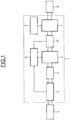
- Figure 1 shows schematically a device 1 for charging and/or generating electric power of a traction system of an electric or hybrid motor vehicle coupled to a battery 2.
- the device is also coupled to a power supply network or to a load 3.
- This device 1 is an integrated device, that is to say installed onboard the vehicle. It is designed, in a recharge mode, to charge the battery in order to supply the power necessary for propulsion and, in a generation mode, to power a load from the current supplied by the battery. It should also be noted that it is designed to charge the battery either from a single-phase power supply network or from a three-phase power supply network. Finally it is designed, in a recharge mode, to return electric power to the power supply network according to a power supply setpoint of the network.
- the device 1 comprises connection means 4 for making it possible to connect the charging device 1 to the power supply network or to the load 3.
- connection means 4 for making it possible to connect the charging device 1 to the power supply network or to the load 3.
- a suitable connection means could be an industrial connector assembly commercially available from Yazaki that is compliant with the SAE standard J1772. Other similar plugs could also be suitable.
- filtering means 5 making it possible to filter the current of the power supply network drawn off by the device 1.
- the device 1 also comprises a first rectifier stage 6 coupled to the output of the filtering means 5 and making it possible to rectify the alternating current originating from the power supply network 3, or to rectify the current that is delivered to it via a second inverter stage 7 connected to the battery 2.
- the first stage 6 and the second stage 7 are controlled by first and second control means respectively 8 and 9 which can be independent controllers.
- the first control means 8 of the input stage 6 receive as an input a signal originating from a module 10 for measuring the output current of the input stage 6, also making it possible, in a recharge mode, to control a regulation of the average current originating from the first rectifier stage 6.
- the average current originating from the first rectifier stage 6 is controlled to be equal to a current value established based on the maximum current supplied by a power supply network 3 and as a function of a coefficient equal to a ratio between a maximum voltage rectified by the first rectifier stage 6 and the voltage of the battery 2.
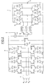
- Figure 2 shows in a more detailed manner an embodiment of a device 1 for charging and/or generating electric power of a traction system of an electric or hybrid motor vehicle coupled to a battery 2.
- the device 1 shown in Figure 2 comprises three available phases.
- the three phases can be coupled to a three-phase power supply network or a single-phase power supply network. In the latter case, the two available phases are coupled to the phase and to the neutral of the single-phase power supply network, and the third available phase is not used.
- the three phases can also be coupled to a load to be powered in three-phase or single-phase mode.
- the first rectifier stage 6 comprises a first rectifying circuit comprising diodes 11a that are in the on-state in a first direction of flow of the current, which diodes are coupled in series to transistors 12a.
- the first rectifying circuit comprises three identical branches coupled in parallel. Each of the branches comprises an arrangement in series comprising successively a diode 11a, two transistors 12a, and a diode 11a. Each branch is also coupled to a distinct phase, the coupling being carried out between the two transistors 12a.
- This first rectifying circuit is coupled in parallel to at least one freewheel diode 13a that is in the on-state in the first direction of flow of the current.
- the first rectifier stage 6 comprises a second rectifying circuit comprising diodes 11b, that are in the on-state in a second direction of flow of the current opposite to the first direction, coupled in series to transistors 12b.
- the second rectifying circuit also comprises three identical branches coupled in parallel. Each of the branches comprises an arrangement in series comprising successively a diode 11b, two transistors 12b and a diode 11b. Each branch is also coupled to a distinct phase, the coupling being carried out between the two transistors 12b.
- This second rectifying circuit is coupled in parallel to at least one freewheel transistor 13b which is in the on-state in the second direction of flow of the current opposite to the first direction of flow.
- the first and the second rectifying circuits are coupled together so as to make only one circuit comprising six rectifying branches and two freewheel branches.
- the first rectifier stage 6 is coupled at the output to a module 10 for measuring the current originating from the input stage 6, such as an ammeter, for the purpose of regulating this current through the control of the first rectifier stage 6.
- the second inverter stage 7 is coupled to the output of the measurement module 10 via three stator coils 14. Each stator coil 14 is coupled at the input to the measurement module 10. Therefore, the current originating from the rectifier input stage 6 is divided in the 3 branches of a circuit of the second inverter stage 7.
- the second inverter stage 7 also comprises a circuit comprising three branches coupled in parallel. Each branch comprises a coupling in series of two arrangements each comprising a diode 15 and a transistor 16 coupled in parallel. The two diodes 16 of one and the same branch are mounted in the same on-state direction.
- Each coil 14 is coupled to a branch of the circuit of the second inverter stage 7. The coupling is carried out between the two arrangements coupled in series.
- the second inverter stage 7 is also coupled to the battery 2.
- the charging of the device 1 can be optimized.
- the optimization of the device 1 consists in adjusting the minimum output average current of the first rectifier stage 6, as a function of the voltage of the battery 2 rather than leaving this current permanently at its highest value. Since the amount of current input into the battery decreases while the battery is being charged at a constant power supply from the network, the minimum output average current of the first rectifier stage 6 can be decreased and is maintained above the value of the current that is input into the battery 2 by a fixed predetermined value of current. This predetermined value of current is chosen to ensure that the output average current of the first rectifier stage 6 is at all times higher than the current input in the battery provided the imperfections, such as ripple, in the output average current signal of the first rectifier stage 6.
- the device 1 is connected to a 400 Volts three-phase power supply network 3 that supplies a current of 32 amps.
- the current in the battery 2 is around 70 Amps at 300 Volts battery voltage. Therefore, the control means 8 set the fixed predetermined value at 20 amps.
- the first control means 8 controls the first stage 6 such that the minimum output average current is equal to 90 amps (i.e. equal to 70 amps of the battery 2 plus the fixed predetermined value of 20 amps).
- the charging device obtains an average voltage at the output of the first rectifier stage 6, that is to say at the terminals of the freewheel diode 13a, that is lower than the voltage of the battery 2.
- the second inverter stage 7 consisting of the traction inverter and the stator coils 14 can then be controlled.
- the low average voltage is due to the freewheel phases, that is to say conduction phases, of the freewheel diode 13a during which the voltage at its terminals is virtually zero, give or take the voltage drop of the junction of the diode 13a.
- each transistor 12a of the first rectifier stage 6 with the freewheel phases, by virtue of the first control means 8 of the input stage. It is therefore possible to directly control the rectifier input stage 6 by adjusting a duty cycle of a transistor-switching signal or by using a regulation loop, or by using a regulation loop and adjusting the duty cycle of the switching signal in order to dispatch the current into the power supply network phases according to a given value coming from regulation loop.
- This power supply network phase current is distributed in high frequency pulses (minimum ten times higher than the network frequency) with variable duty cycle, varying with a current setpoint.
- the diode 13A acts as a free wheeling diode when all transistors are in the off-state, thus preventing the rectifier input stage 6 from abruptly stopping the current flow in the stator.
- the voltage produced in this case contains lower-frequency harmonics, for example up to six times the power supply network frequency, which will then be less filtered by the stator coils 14. Therefore, a compromise can be found between having reduced losses in the first rectifier stage 6 and losses (mainly by heat) induced by the lower-frequency harmonics in the stator coils 14.
- the first control means 8 of the first stage 6 control the current drawn from the three-phase power supply network 3 by cyclic ratios of the current pulses that are applied to the control electrodes of the transistors 12a of the first rectifier stage 6.
- the second inverter stage 7 comprises elements specific to the traction of the electric vehicle.
- the inverter stage of the traction system in this instance forms the second stage 7 of the device 1.
- this second stage is to supply a defined charging current in the battery, necessarily lower than the average current originating from the first rectifier stage 6, based on the regulated current originating from the first rectifier stage 6.
- each branch of the second inverter stage 7 can also be controlled by second control means 9 which can be independent of the control means 8 of the first stage 6.
- the pulse phase of each branch of the circuit of the second inverter stage 7 is, for example, offset by a third of a period.
- Each branch of the circuit of the second inverter stage 7 can be driven individually with a regulation loop which is specific to it, or collectively, that is to say the same cyclic ratio is applied to the control of each branch.
- the second rectifying circuit comprising the diodes 11b, the transistors 12b and the freewheel transistor 13b which are in the on-state in the second direction of flow of the current makes it possible to make the charger reversible. That is to say that the device 1 can also be used in an electric power generation mode. Operation in generation mode is symmetrical with the function in recharge mode except for the freewheel phase which is controlled by a freewheel transistor 13b.
- the control of the first stage 6 differs depending on the connection of the device 1. Specifically, the control will be different if the device 1 is connected to a power supply network and returns electric power to the power supply network, in the event that the device 1 is connected to a load which is to be powered by the device 1.
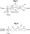
- Figure 3 shows an example of a control means 20 for a current regulation of the first stage 6 when the device 1 is connected to a power supply network.
- control consists in controlling the amplitude, that is the power, of the current in phase with the voltage injected into the network.
- the control means 20 are included in the first control means 8 of the first rectifier stage 6.
- the control means 20 are made up so as to regulate the current generated in the power supply network. They also allow the placing in phase of the current setpoint, the voltage of the network, the closed-loop control of the amplitude of this current, the putting in place of a modulation strategy which generates the control of the transistors. They comprise computing means 21, for example, a digital controller, phasing means 22 such a PLL (Phase Locked Loop) circuit, first comparison means 23, current regulation means 24, summing means 25, proaction means 26, and strategic means 27, such means 23-27 can be implemented as mathematical functions in the digital controller.
- phasing means 22 such a PLL (Phase Locked Loop) circuit
- first comparison means 23 current regulation means
- summing means 25 proaction means 26, and strategic means 27, such means 23-27 can be implemented as mathematical functions in the digital controller.
- the principle of control consists in locking in the current generated in the power supply network so as to control the power supplied and the shape of the current in order to satisfy the conditions of connection imposed by the manager of the power supply network on the one hand, and to maximize the power factor on the other hand, the power factor being defined by the cosine of the difference in phase between the current and the voltage of the network.
- a current setpoint A Inetwork corresponding to the amplitude of the current that the device wishes to reinject into the power supply network, is delivered to the computing means 21 also receiving as an input a measurement of the voltage of the power supply network U Network , the voltage imposed by the power supply network distributor, via phasing means 22, such as a phase-locked loop for example.
- the computing means 21 therefore deliver as an output a setpoint of network current in phase with the voltage at the terminals of the network.
- the setpoint of network current is delivered to first comparison means 23 which also receive as an input a measurement of the network current corresponding to the current really returned by the device 1 to the power supply network.
- the first comparison means 23 determine the difference that exists between the network current setpoint and the network current measurement, and deliver the value of this difference to the current regulation means 24.
- the current regulation means 24 then deliver as an output a regulation signal to the summing means 25 which also receive as an input the network current setpoint originating from the computing means 21 via proaction means 26 capable of modifying the network current setpoint.
- the summing means 25 deliver as an output a signal resulting from the two input signals to the strategic means 27 capable of determining a control of the device 1, for example according to values stored on a memory of the digital controller in a Look-Up table, in order to regulate the current of the device 1 generated to the power supply network.
- Figure 4 shows an example of control means 30 for regulating the voltage of the first stage 6 when the device 1 is connected to a load.
- the control means 30 are included in the first control means 8 of the first rectifier stage 6.
- the load must be supplied with a regulated voltage irrespective of the current delivered, within the limit of the maximum allowed current.
- the voltage-regulation control means 30 comprise second comparison means 31, voltage-regulation means 32, saturation means 33 and strategy means 34. These means 30-34 can be implemented as mathematical functions in the digital controller.
- a voltage setpoint corresponding to the voltage that the device 1 must deliver to the connected load, is delivered to the second comparison means 31 which also receive as an input a measurement of the voltage delivered by the device 1 at the terminals of the load, U load .
- the second comparison means 31 determine the difference between the two signals and deliver the result signal to the voltage-regulation means 32.
- the voltage-regulation means 32 determine a voltage-regulation signal which they deliver to the saturation means 33 which are capable of saturating the amplitude of the current delivered by the device 1 to the load so as not to overload the converter, thus reducing the voltage applied to the load when its impedance becomes too low, so as to limit the delivered current to its maximum.
- the saturation means 33 deliver as an output a signal, saturated if necessary, to the strategy means 34 which are capable of determining a control of the device 1, for example by matching the signal received from the saturation means 33 to a desired voltage value by means of a Look-up table, in order to regulate the voltage of the device 1 generated at the terminals of the load.
- control means 9 can be substantially the same than control means 8. These controls means can be implemented in a single common controller or in two separate and distinct controllers.
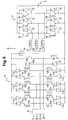
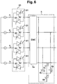
- FIG. 5 shows another embodiment of a device 1.
- the three phases are marked P 1 , P 2 and P 3 and neutral is marked N.
- a second freewheel diode 17 is added to the first freewheel circuit of the first rectifier stage 6, and a second freewheel transistor 18 is added to the second freewheel circuit of the first rectifier stage 6.
- the second freewheel circuit 17 is coupled in series upstream of the first freewheel diode 13a in the first on-state direction.
- the second freewheel circuit 18 is coupled in series with the first freewheel circuit 13b in the second on-state direction.
- the neutral wire is coupled to the branch formed by the two freewheel diodes 13a and 17 connected in series, the coupling being made between the two freewheel diodes 13a and 17, and the branch formed by the two freewheel circuits 13b and 18 connected in series, the coupling being made between the two freewheel transistors 13b and 18.
- the device 1 produced according to this embodiment with a single-phase power supply network by coupling the neutral wire of the single-phase power supply network to the dedicated input coupled to the branch comprising the two freewheel diodes 13a and 17.
- Figure 6 shows schematically means 60 for protecting the integrated filtering means 5.
- the filtering means 5 comprise an electromagnetic compatibility (EMC) filter 5a, and filtering capacitors 5b placed "in star formation" so as to perform filtering between each phase.
- EMC electromagnetic compatibility
- the EMC filter 5a is, for example, a common-mode inductor and capacitor filter making it possible to filter the current pulses generated by the transistors of the first stage 6 and of the second stage 7 of the device 1.
- the filtering means 5 make it possible to filter the current thus absorbed so that the current meets the network-connection requirements imposed by the network operators, in terms of harmonics and those of the motor vehicle field.
- a neutral-filtering capacitor 5c is also placed between the neutral wire N and the common point C of the filtering capacitors 5b.
- the latter capacitor 5c makes it possible to carry out filtering between the neutral wire and the phases.
- connection of the device 1 to a power supply network can cause a generation of high current peaks since the difference between the initial voltage of the input capacitors, such as the EMC filtering means 5a and/or the filtering capacitors 5b, and the voltage of the power supply network is great at the time of connection.
- the protection means 60 comprise a triac 61, or an arrangement equivalent to a triac such as two thyristors 62 coupled in an antiparallel manner, inserted between the means 4 for connection to the power supply network 3 and the filtering means 5 on each of the phases P 1 , P 2 , P 3 , and N depending on the embodiment.
- the protection means 60 operate according to a principle of preloading of the filtering capacitors which makes it possible, via the control of the trigger-gate of the triac 61 to limit the conduction and thus the current peak on start-up.
- Figure 7 shows a flow chart of a method for generating electric power of a device 1 for charging and/or generating electric power of a traction system of a motor vehicle to a electricity power supply network according to one embodiment.
- a setpoint of network current amplitude A Inetwork is delivered corresponding to the amplitude of the current that it is desired to deliver to the network from the device 1.
- a subsequent step 702 the network power supply voltage U Network imposed by the distributor is measured. This voltage is measured and injected into phasing means 22, such as a phase-locked loop, before being inserted, in a step 703, into a computing means 21 receiving the network current amplitude setpoint also as an input, and delivering as an output a network current setpoint Setpoint(I Network ).
- phasing means 22 such as a phase-locked loop
- step 704 the current I Network delivered by the device 1 to the power supply network is measured in order to compare it, in a step 705, with the network setpoint Setpoint(I Network ).
- a current regulation is determined based on the difference determined in step 705.
- the regulation thus determined is added, in a step 707, to the network current setpoint Setpoint(I Network ) previously processed by proaction means.
- the resultant signal is injected into strategic means 27 which determine a control of the device 1 so that the latter delivers the desired current to the power supply network.
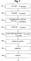
- Figure 8 shows a flow chart of a method of powering a load from a device for charging and/or electricity generation of a traction system of a motor vehicle according to one embodiment.
- a load voltage setpoint U setpoint is delivered corresponding to the voltage that it is desired to deliver to the load from the device 1.
- a subsequent step 802 the voltage U load delivered by the device 1 to the terminals of the load is measured.
- the voltage setpoint U setpoint is compared with the measured voltage U load , and the measured difference is delivered to regulation means 32 which determine, in a subsequent step 804, a voltage regulation which makes it possible to deliver a current setpoint to be applied by the device 1 to the load in order to have the desired voltage at the charge.
- a subsequent step 805 the current setpoint determined in the previous step is saturated so as not to overload the converter, which has the effect of reducing the voltage applied to the load when its impedance becomes too low.
- the resultant signal is injected into the strategy means 34 which determine the control of the device 1 in order to deliver the current corresponding to the setpoint in order to have the desired voltage at the terminals of the load.
- the device 1 thus described makes it possible to dispense with the constraint which demands that the battery voltage is always higher than the maximum voltage of the power supply network.
- the device 1 makes it possible to power a load from a motor vehicle, in three-phase or in single-phase mode, without having need of a contactor.
- the device 1 also makes it possible to return electric power generated by the device to a power supply network which is connected to it.
Claims (15)
- Elektronische Vorrichtung (1) zum Laden und Erzeugen von elektrischer Leistung für ein Traktionssystem eines mit einer Batterie (2) gekoppelten Kraftfahrzeugs, umfassend eine erste Gleichrichterstufe (6), die dazu ausgelegt ist, direkt mit einem einphasigen oder einem dreiphasigen Stromversorgungsnetzwerk oder mit einer anzutreibenden Last (3) verbunden zu werden, eine zweite Inverterstufe (7), die dazu ausgelegt ist, mit der Batterie verbunden zu werden, und Mittel zum Regeln des durchschnittlichen Stroms, der zwischen der ersten Stufe (6) und der zweiten Stufe (7) fließt, wobei sie Steuerungsmittel (8) umfasst, die in der Lage sind, entweder einen Übergang von elektrischer Leistung zwischen dem Stromversorgungsnetzwerk und der Batterie (2) in einem Auflademodus oder die Bereitstellung einer passiven Last im Erzeugungsmodus zu steuern, gekennzeichnet dadurch, dass
das Steuerungsmittel Mittel zum Einstellen, im Auflademodus, des durchschnittlichen Stroms, der aus der ersten Gleichrichterstufe stammt, auf einen basierend auf dem maximalen, durch das Stromversorgungsnetzwerk bereitgestellten Strom und als eine Funktion eines Koeffizienten gleich einem Verhältnis zwischen einer maximalen, durch die erste Gleichrichterstufe gleichgerichteten Spannung und der Spannung der Batterie festgelegten Stromwert umfasst. - Vorrichtung nach Anspruch 1, dadurch gekennzeichnet, dass das Steuerungsmittel (8) Stromregelungsmittel (20), das in der Lage ist, den Stromversorgungsstrom des Netzwerks als eine Funktion eines Stromeinstellpunkts des Stromversorgungsnetzwerks zu regeln, und ein Spannungsregelungsmittel (30), das in der Lage ist, die Spannung an den Anschlüssen einer Last zu regeln, umfasst.
- Vorrichtung nach einem der Ansprüche 1 oder 2, dadurch gekennzeichnet, dass die erste Gleichrichterstufe (6) ein erstes gesteuertes Gleichrichtungsmittel, das in der Lage ist, den Strom in eine erste Richtung in einem eingeschalteten Zustand gleichzurichten, und ein zweites gesteuertes Gleichrichtungsmittel, das in der Lage ist, den Strom in eine zweite, der ersten Richtung im eingeschalteten Zustand entgegengesetzte Richtung im eingeschalteten Zustand gleichzurichten, umfasst.
- Vorrichtung nach einem der Ansprüche 1 bis 3, dadurch gekennzeichnet, dass die erste Stufe (6) Freilaufmittel umfasst, das in der Lage ist, dem Strom zu ermöglichen, in die zweite Stufe (7) zu fließen, wenn die anderen Elemente der ersten Stufe (6) in einem ausgeschalteten Zustand sind.
- Vorrichtung nach Anspruch 4, dadurch gekennzeichnet, dass das Freilaufmittel eine erste Freilaufschaltung, die in der Lage ist, dem Strom zu ermöglichen, in eine Richtung zu fließen, und eine zweite Freilaufschaltung, die in der Lage ist, dem Strom zu ermöglichen, in eine andere, der Richtung der ersten Schaltung entgegengesetzte Richtung zu fließen, umfasst.
- Vorrichtung nach einem der Ansprüche 4 oder 5, dadurch gekennzeichnet, dass das Freilaufmittel zumindest eine Freilaufdiode (13a) und/oder zumindest einen Freilauftransistor (13b) umfasst.
- Vorrichtung nach einem der Ansprüche 1 bis 6, wobei die Vorrichtung (1) dazu ausgelegt ist, in einem Kraftfahrzeug mit einer elektrischen Traktionsvorrichtung montiert zu werden, dadurch gekennzeichnet, dass die zweite Stufe (7) aus der Traktionsvorrichtung des Fahrzeugs besteht.
- Vorrichtung nach einem der Ansprüche 1 bis 7, dadurch gekennzeichnet, dass sie Filterungsmittel (5), die dazu ausgeführt sind, in das Fahrzeug integriert zu werden, umfasst, die in der Lage sind, den durch die Vorrichtung (1) während des Ladens der Batterie (2) absorbierten Stromversorgungsnetzwerkstrom zu filtern.
- Vorrichtung nach Anspruch 8, dadurch gekennzeichnet, dass die Filterungsmittel (5) Schutzmittel (60) umfassen, die in der Lage sind, die Schaltung vor Stromspitzen zu schützen, wenn die Vorrichtung (1) mit einem Stromversorgungsnetzwerk verbunden ist.
- Verfahren zum Laden und Erzeugen von Leistung für ein Traktionssystem eines mit einer Batterie (2) gekoppelten Kraftfahrzeugs unter Verwendung einer elektronischen Vorrichtung, die Folgendes umfasst:- eine erste Gleichrichterstufe (6), die dazu ausgelegt ist, mit einem Stromversorgungsnetzwerk oder einer anzutreibenden Last (3) verbunden zu werden,- eine zweite Inverterstufe (7), die dazu ausgelegt ist, mit der Batterie verbunden zu werden,- und Mittel zum Regeln des durchschnittlichen Stroms, der zwischen der ersten Stufe (6) und der zweiten Stufe (7) fließt,wobei eine Übertragung von elektrischer Leistung zwischen dem Stromversorgungsnetzwerk und der Batterie (2) in einem Auflademodus gesteuert wird, oder andernfalls das Antreiben einer Last in einem Erzeugungsmodus gesteuert wird, und wobei im Auflademodus der durchschnittliche Strom, der zwischen der ersten Stufe und der zweiten Stufe fließt, auf einen Stromwert eingestellt wird, der basierend auf dem durch das Stromversorgungsnetzwerk bereitgestellten maximalen Strom und als eine Funktion eines Koeffizienten gleich einem Verhältnis zwischen einer maximalen, durch die erste Gleichrichterstufe gleichgerichteten Spannung und der Spannung der Batterie festgelegt wird.
- Verfahren nach Anspruch 10, wobei, wenn eine Übertragung von elektrischer Leistung zwischen dem Stromversorgungsnetzwerk und der Batterie (2) gesteuert wird, der Strom, der in jeder Phase des Stromversorgungsnetzwerks erzeugt wird, basierend auf einem Stromeinstellpunkt geregelt wird, der basierend auf einer Messung der Spannung des Stromversorgungsnetzwerks erzeugt wird.
- Verfahren nach Anspruch 10, wobei, wenn das Antreiben einer Last gesteuert wird, die Spannung an den Anschlüssen der Last mithilfe einer Regelschleife geregelt wird.
- Verfahren nach einem der Ansprüche 10 bis 12, wobei dem Strom einer zweiten Stufe (7) ermöglicht wird, in Freilaufmitteln in einer Freilaufphase zu fließen.
- Verfahren nach einem der Ansprüche 10 bis 13, wobei der Strom des Stromversorgungsnetzwerks mithilfe von integrierten Filterungsmitteln (5) gefiltert wird.
- Verfahren nach Anspruch 14, wobei die integrierten Filterungsmittel (5) vor Stromspitzen geschützt sind durch Verbindung des Stromversorgungsnetzwerks mithilfe von Schutzmitteln (60) von Triacs durch Vorladen von Filterungskondensatoren der Filterungsmittel.
Applications Claiming Priority (2)
| Application Number | Priority Date | Filing Date | Title |
|---|---|---|---|
| FR0954024A FR2946810B1 (fr) | 2009-06-16 | 2009-06-16 | Dispositif de charge rapide reversible pour vehicule electrique |
| PCT/EP2010/058484 WO2010146092A1 (en) | 2009-06-16 | 2010-06-16 | Rapid reversible charging device for an electric vehicle |
Publications (2)
| Publication Number | Publication Date |
|---|---|
| EP2443000A1 EP2443000A1 (de) | 2012-04-25 |
| EP2443000B1 true EP2443000B1 (de) | 2018-08-08 |
Family
ID=41528715
Family Applications (1)
| Application Number | Title | Priority Date | Filing Date |
|---|---|---|---|
| EP10723612.7A Active EP2443000B1 (de) | 2009-06-16 | 2010-06-16 | Reversible schnellaufladungsvorrichtung für ein elektrofahrzeug |
Country Status (8)
| Country | Link |
|---|---|
| US (1) | US8917046B2 (de) |
| EP (1) | EP2443000B1 (de) |
| JP (1) | JP5738759B2 (de) |
| KR (1) | KR101573919B1 (de) |
| CN (1) | CN102015355B (de) |
| BR (1) | BRPI1010593B1 (de) |
| FR (1) | FR2946810B1 (de) |
| WO (1) | WO2010146092A1 (de) |
Families Citing this family (27)
| Publication number | Priority date | Publication date | Assignee | Title |
|---|---|---|---|---|
| JP4506891B2 (ja) * | 2008-12-23 | 2010-07-21 | ダイキン工業株式会社 | 電流形電力変換回路 |
| FR2964510B1 (fr) * | 2010-09-07 | 2013-06-14 | Renault Sa | Dispositif de recharge pour batterie automobile et procede de gestion du dispositif. |
| FR2974253B1 (fr) | 2011-04-14 | 2013-04-26 | Renault Sas | Dispositif de charge d'une batterie d'un vehicule automobile a partir d'un reseau d'alimentation monophase, et procede de commande du dispositif |
| FR2975843B1 (fr) * | 2011-05-23 | 2013-05-17 | Renault Sa | Procede de commande des interrupteurs d'un redresseur de courant connecte a un chargeur embarque. |
| WO2012177498A2 (en) * | 2011-06-21 | 2012-12-27 | Carrier Corporation | Variable frequency drive voltage boost to improve utilization |
| DE102011107737A1 (de) | 2011-07-14 | 2013-01-17 | Gottfried Wilhelm Leibniz Universität Hannover | Verfahren zur Steuerung eines Direktumrichters, elektronische Steuerungseinrichtung dafür, Direktumrichter und Computerprogramm |
| WO2013111127A1 (en) * | 2012-01-26 | 2013-08-01 | Better Place GmbH | Charge spot device for charging electric vehicles |
| DE102012014178A1 (de) * | 2012-01-31 | 2013-08-01 | Volkswagen Aktiengesellschaft | Vorrichtung und Verfahren zum Laden mindestens einer Traktionsbatterie eines Elektrofahrzeugs |
| DE102012007158A1 (de) | 2012-04-07 | 2013-10-10 | Daimler Ag | Pulswechselrichter mit Stromzwischenkreis zum Fahren und Laden eines batteriebetriebenen Elektrofahrzeugs |
| FR2992779B1 (fr) | 2012-06-29 | 2014-06-13 | Renault Sa | Methode et dispositifs pour maximiser la duree de vie d'une batterie de traction d'un vehicule electrique, notamment une batterie li-ion |
| FR2996071B1 (fr) * | 2012-09-25 | 2014-09-05 | Renault Sa | Systeme de charge d'une batterie d'un vehicule automobile |
| US9385620B1 (en) * | 2013-01-10 | 2016-07-05 | Lockheed Martin Corporation | AC link converter switch engine |
| CN104253465B (zh) * | 2013-06-28 | 2017-01-04 | 比亚迪股份有限公司 | 电动汽车的充电控制系统及具有其的电动汽车 |
| CN104253464B (zh) | 2013-06-28 | 2017-05-03 | 比亚迪股份有限公司 | 电动汽车之间相互充电的系统及充电连接器 |
| TWI513167B (zh) * | 2013-10-22 | 2015-12-11 | Ind Tech Res Inst | 電動車輛之電力轉換系統 |
| US9238415B2 (en) | 2013-11-20 | 2016-01-19 | General Electric Company | Apparatus for rapid charging using onboard power electronics and method of manufacturing same |
| WO2015075212A1 (de) * | 2013-11-22 | 2015-05-28 | Hochschule Für Angewandte Wissenschaften Deggendorf | Ladestation für elektrofahrzeuge |
| EP2875985A1 (de) * | 2013-11-22 | 2015-05-27 | Hochschule für angewandte Wissenschaften Deggendorf | Ladestation für Elektrofahrzeuge mit integriertem Energiespeicher |
| FR3014615B1 (fr) * | 2013-12-05 | 2015-12-18 | Renault Sas | Dispositif de charge reversible ameliore pour vehicule electrique |
| FR3014611B1 (fr) * | 2013-12-10 | 2016-02-05 | Renault Sas | Dispositif de charge pour vehicule electrique avec une chaine de traction a machine a reluctance commutee |
| FR3026244B1 (fr) * | 2014-09-22 | 2017-05-12 | Renault Sas | Dispositif et procede de determination d'une consigne corrigee du courant neutre d'un chargeur sans isolation galvanique de batterie de vehicule automobile electrique ou hybride |
| JP6113321B1 (ja) * | 2016-04-05 | 2017-04-12 | 三菱電機株式会社 | 電力変換制御システム |
| DE102016218304B3 (de) * | 2016-09-23 | 2018-02-01 | Volkswagen Aktiengesellschaft | Vorrichtung zur Spannungswandlung, Traktionsnetz und Verfahren zum Laden einer Batterie |
| US11217996B2 (en) | 2017-10-13 | 2022-01-04 | The Governing Council Of The University Of Toronto | On-board bidirectional AC fast charger for electric vehicles |
| EP4236048A3 (de) | 2019-05-24 | 2023-10-25 | Huawei Digital Power Technologies Co., Ltd. | Integriertes ladegerät und motorsteuerungssystem mit einem transformator und mehrstufigen stromrichtern |
| CN112550022B (zh) * | 2019-09-25 | 2022-04-15 | 比亚迪股份有限公司 | 能量转换装置及车辆 |
| DE102020119108A1 (de) | 2020-07-21 | 2022-01-27 | Dr. Ing. H.C. F. Porsche Aktiengesellschaft | Gleichstrom-Filtervorrichtung |
Family Cites Families (16)
| Publication number | Priority date | Publication date | Assignee | Title |
|---|---|---|---|---|
| US5127085A (en) * | 1991-04-01 | 1992-06-30 | General Motors Corporation | Ride-through protection circuit for a voltage source inverter traction motor drive |
| JPH07193910A (ja) * | 1993-04-09 | 1995-07-28 | Hitachi Ltd | 電気自動車の制御装置 |
| JP3232431B2 (ja) | 1995-09-08 | 2001-11-26 | 株式会社日立製作所 | 電力変換装置 |
| EP0834977A3 (de) * | 1996-08-08 | 1999-04-14 | Schmidhauser AG | Einrichtung zum Laden mindestens eines Akkumulators, insbesondere eines Akkumulators für ein elektrisch angetriebenes Fahrzeug sowie ein Verfahren zum Betrieb dieser Einrichtung |
| US5952812A (en) * | 1996-11-26 | 1999-09-14 | Nippon Soken, Inc. | AC-DC power converting device |
| JP3729617B2 (ja) * | 1997-09-25 | 2005-12-21 | アイシン・エィ・ダブリュ株式会社 | 充電制御装置及び充電制御方法 |
| US6172480B1 (en) * | 1998-10-23 | 2001-01-09 | Primetech Electronics, Inc. | Compact fast battery charger |
| US6337801B2 (en) * | 1999-12-16 | 2002-01-08 | Virginia Tech Intellectual Properties, Inc. | Three-phase zero-current-transition (ZCT) inverters and rectifiers with three auxiliary switches |
| US6683389B2 (en) * | 2000-06-30 | 2004-01-27 | Capstone Turbine Corporation | Hybrid electric vehicle DC power generation system |
| US7746024B2 (en) * | 2006-03-07 | 2010-06-29 | Hamilton Sundstrand Corporation | Electric engine start system with active rectifier |
| US7476987B2 (en) * | 2006-04-25 | 2009-01-13 | The University Of New Brunswick | Stand-alone wind turbine system, apparatus, and method suitable for operating the same |
| US20100266875A1 (en) * | 2006-11-13 | 2010-10-21 | Ryan Somogye | Fuel Cell Power Management Module |
| US7598623B2 (en) * | 2006-12-29 | 2009-10-06 | Cummins Power Generation Ip, Inc. | Distinguishing between different transient conditions for an electric power generation system |
| JP4441691B2 (ja) * | 2007-02-06 | 2010-03-31 | 国立大学法人東京工業大学 | 交流/直流電力変換装置 |
| JP4770798B2 (ja) * | 2007-06-15 | 2011-09-14 | 株式会社豊田自動織機 | 電源装置 |
| US8503204B2 (en) * | 2011-08-05 | 2013-08-06 | Infineon Technologies Ag | Power converter circuit |
-
2009
- 2009-06-16 FR FR0954024A patent/FR2946810B1/fr active Active
-
2010
- 2010-06-16 WO PCT/EP2010/058484 patent/WO2010146092A1/en active Application Filing
- 2010-06-16 BR BRPI1010593-0A patent/BRPI1010593B1/pt active IP Right Grant
- 2010-06-16 JP JP2011519196A patent/JP5738759B2/ja active Active
- 2010-06-16 KR KR1020117030236A patent/KR101573919B1/ko active IP Right Grant
- 2010-06-16 US US12/866,997 patent/US8917046B2/en active Active
- 2010-06-16 EP EP10723612.7A patent/EP2443000B1/de active Active
- 2010-06-16 CN CN2010800011792A patent/CN102015355B/zh active Active
Non-Patent Citations (1)
| Title |
|---|
| None * |
Also Published As
| Publication number | Publication date |
|---|---|
| BRPI1010593A2 (pt) | 2016-03-15 |
| BRPI1010593B1 (pt) | 2019-10-01 |
| EP2443000A1 (de) | 2012-04-25 |
| CN102015355A (zh) | 2011-04-13 |
| FR2946810A1 (fr) | 2010-12-17 |
| US20110254494A1 (en) | 2011-10-20 |
| WO2010146092A1 (en) | 2010-12-23 |
| KR101573919B1 (ko) | 2015-12-02 |
| JP5738759B2 (ja) | 2015-06-24 |
| KR20120051608A (ko) | 2012-05-22 |
| US8917046B2 (en) | 2014-12-23 |
| JP2011526779A (ja) | 2011-10-13 |
| FR2946810B1 (fr) | 2012-12-14 |
| CN102015355B (zh) | 2013-05-01 |
Similar Documents
| Publication | Publication Date | Title |
|---|---|---|
| EP2443000B1 (de) | Reversible schnellaufladungsvorrichtung für ein elektrofahrzeug | |
| US11114883B2 (en) | Method for controlling a charging device on board an electric or hybrid vehicle | |
| US10562404B1 (en) | Integrated onboard chargers for plug-in electric vehicles | |
| US10763690B2 (en) | Vehicle-side charging circuit for a vehicle with electric drive, and method for operating a vehicle-side current converter, and use of at least one winding of a vehicle-side electric machine for intermediate storagectrical machine for buffer | |
| US20220402390A1 (en) | A multimodal converter for interfacing with multiple energy sources | |
| US11817769B2 (en) | Multibridge power converter with multiple outputs | |
| DK2020726T3 (en) | A method for supplying beredskabshjælpeladninger, hjælpeomformere rail vessel for this method | |
| EP2406098B1 (de) | Schnellaufladevorrichtung für ein elektrofahrzeug | |
| CN104659895B (zh) | 用于使用车载电力电子装置快速充电的设备及其制造方法 | |
| KR101284331B1 (ko) | 친환경 차량의 충전장치 및 방법 | |
| US7956584B2 (en) | Electric power generation system with multiple alternators driven by a common prime mover | |
| US9120390B2 (en) | Apparatus for transferring energy using onboard power electronics and method of manufacturing same | |
| WO2013102960A1 (ja) | 電気車制御装置及び電気車 | |
| JP6259202B2 (ja) | 変圧器タップ切替え回路およびそれを作製する方法 | |
| EP3776798A1 (de) | Eingangsleistungssteuerung einer ladestation für elektrofahrzeuge | |
| US7005840B2 (en) | Interface for supplying power to a load from an electrical power supply network |
Legal Events
| Date | Code | Title | Description |
|---|---|---|---|
| PUAI | Public reference made under article 153(3) epc to a published international application that has entered the european phase |
Free format text: ORIGINAL CODE: 0009012 |
|
| 17P | Request for examination filed |
Effective date: 20111109 |
|
| AK | Designated contracting states |
Kind code of ref document: A1 Designated state(s): AL AT BE BG CH CY CZ DE DK EE ES FI FR GB GR HR HU IE IS IT LI LT LU LV MC MK MT NL NO PL PT RO SE SI SK SM TR |
|
| DAX | Request for extension of the european patent (deleted) | ||
| GRAP | Despatch of communication of intention to grant a patent |
Free format text: ORIGINAL CODE: EPIDOSNIGR1 |
|
| STAA | Information on the status of an ep patent application or granted ep patent |
Free format text: STATUS: GRANT OF PATENT IS INTENDED |
|
| INTG | Intention to grant announced |
Effective date: 20180319 |
|
| GRAS | Grant fee paid |
Free format text: ORIGINAL CODE: EPIDOSNIGR3 |
|
| GRAA | (expected) grant |
Free format text: ORIGINAL CODE: 0009210 |
|
| STAA | Information on the status of an ep patent application or granted ep patent |
Free format text: STATUS: THE PATENT HAS BEEN GRANTED |
|
| AK | Designated contracting states |
Kind code of ref document: B1 Designated state(s): AL AT BE BG CH CY CZ DE DK EE ES FI FR GB GR HR HU IE IS IT LI LT LU LV MC MK MT NL NO PL PT RO SE SI SK SM TR |
|
| REG | Reference to a national code |
Ref country code: GB Ref legal event code: FG4D |
|
| REG | Reference to a national code |
Ref country code: CH Ref legal event code: EP Ref country code: AT Ref legal event code: REF Ref document number: 1026599 Country of ref document: AT Kind code of ref document: T Effective date: 20180815 |
|
| REG | Reference to a national code |
Ref country code: IE Ref legal event code: FG4D |
|
| REG | Reference to a national code |
Ref country code: DE Ref legal event code: R096 Ref document number: 602010052511 Country of ref document: DE |
|
| REG | Reference to a national code |
Ref country code: NL Ref legal event code: MP Effective date: 20180808 |
|
| REG | Reference to a national code |
Ref country code: LT Ref legal event code: MG4D |
|
| REG | Reference to a national code |
Ref country code: AT Ref legal event code: MK05 Ref document number: 1026599 Country of ref document: AT Kind code of ref document: T Effective date: 20180808 |
|
| REG | Reference to a national code |
Ref country code: DE Ref legal event code: R079 Ref document number: 602010052511 Country of ref document: DE Free format text: PREVIOUS MAIN CLASS: B60L0011180000 Ipc: B60L0050500000 |
|
| PG25 | Lapsed in a contracting state [announced via postgrant information from national office to epo] |
Ref country code: LT Free format text: LAPSE BECAUSE OF FAILURE TO SUBMIT A TRANSLATION OF THE DESCRIPTION OR TO PAY THE FEE WITHIN THE PRESCRIBED TIME-LIMIT Effective date: 20180808 Ref country code: PL Free format text: LAPSE BECAUSE OF FAILURE TO SUBMIT A TRANSLATION OF THE DESCRIPTION OR TO PAY THE FEE WITHIN THE PRESCRIBED TIME-LIMIT Effective date: 20180808 Ref country code: IS Free format text: LAPSE BECAUSE OF FAILURE TO SUBMIT A TRANSLATION OF THE DESCRIPTION OR TO PAY THE FEE WITHIN THE PRESCRIBED TIME-LIMIT Effective date: 20181208 Ref country code: AT Free format text: LAPSE BECAUSE OF FAILURE TO SUBMIT A TRANSLATION OF THE DESCRIPTION OR TO PAY THE FEE WITHIN THE PRESCRIBED TIME-LIMIT Effective date: 20180808 Ref country code: NL Free format text: LAPSE BECAUSE OF FAILURE TO SUBMIT A TRANSLATION OF THE DESCRIPTION OR TO PAY THE FEE WITHIN THE PRESCRIBED TIME-LIMIT Effective date: 20180808 Ref country code: BG Free format text: LAPSE BECAUSE OF FAILURE TO SUBMIT A TRANSLATION OF THE DESCRIPTION OR TO PAY THE FEE WITHIN THE PRESCRIBED TIME-LIMIT Effective date: 20181108 Ref country code: SE Free format text: LAPSE BECAUSE OF FAILURE TO SUBMIT A TRANSLATION OF THE DESCRIPTION OR TO PAY THE FEE WITHIN THE PRESCRIBED TIME-LIMIT Effective date: 20180808 Ref country code: FI Free format text: LAPSE BECAUSE OF FAILURE TO SUBMIT A TRANSLATION OF THE DESCRIPTION OR TO PAY THE FEE WITHIN THE PRESCRIBED TIME-LIMIT Effective date: 20180808 Ref country code: NO Free format text: LAPSE BECAUSE OF FAILURE TO SUBMIT A TRANSLATION OF THE DESCRIPTION OR TO PAY THE FEE WITHIN THE PRESCRIBED TIME-LIMIT Effective date: 20181108 Ref country code: GR Free format text: LAPSE BECAUSE OF FAILURE TO SUBMIT A TRANSLATION OF THE DESCRIPTION OR TO PAY THE FEE WITHIN THE PRESCRIBED TIME-LIMIT Effective date: 20181109 |
|
| PG25 | Lapsed in a contracting state [announced via postgrant information from national office to epo] |
Ref country code: ES Free format text: LAPSE BECAUSE OF FAILURE TO SUBMIT A TRANSLATION OF THE DESCRIPTION OR TO PAY THE FEE WITHIN THE PRESCRIBED TIME-LIMIT Effective date: 20180808 Ref country code: HR Free format text: LAPSE BECAUSE OF FAILURE TO SUBMIT A TRANSLATION OF THE DESCRIPTION OR TO PAY THE FEE WITHIN THE PRESCRIBED TIME-LIMIT Effective date: 20180808 Ref country code: LV Free format text: LAPSE BECAUSE OF FAILURE TO SUBMIT A TRANSLATION OF THE DESCRIPTION OR TO PAY THE FEE WITHIN THE PRESCRIBED TIME-LIMIT Effective date: 20180808 Ref country code: AL Free format text: LAPSE BECAUSE OF FAILURE TO SUBMIT A TRANSLATION OF THE DESCRIPTION OR TO PAY THE FEE WITHIN THE PRESCRIBED TIME-LIMIT Effective date: 20180808 |
|
| PG25 | Lapsed in a contracting state [announced via postgrant information from national office to epo] |
Ref country code: EE Free format text: LAPSE BECAUSE OF FAILURE TO SUBMIT A TRANSLATION OF THE DESCRIPTION OR TO PAY THE FEE WITHIN THE PRESCRIBED TIME-LIMIT Effective date: 20180808 Ref country code: IT Free format text: LAPSE BECAUSE OF FAILURE TO SUBMIT A TRANSLATION OF THE DESCRIPTION OR TO PAY THE FEE WITHIN THE PRESCRIBED TIME-LIMIT Effective date: 20180808 Ref country code: CZ Free format text: LAPSE BECAUSE OF FAILURE TO SUBMIT A TRANSLATION OF THE DESCRIPTION OR TO PAY THE FEE WITHIN THE PRESCRIBED TIME-LIMIT Effective date: 20180808 Ref country code: RO Free format text: LAPSE BECAUSE OF FAILURE TO SUBMIT A TRANSLATION OF THE DESCRIPTION OR TO PAY THE FEE WITHIN THE PRESCRIBED TIME-LIMIT Effective date: 20180808 |
|
| REG | Reference to a national code |
Ref country code: DE Ref legal event code: R097 Ref document number: 602010052511 Country of ref document: DE |
|
| PG25 | Lapsed in a contracting state [announced via postgrant information from national office to epo] |
Ref country code: SM Free format text: LAPSE BECAUSE OF FAILURE TO SUBMIT A TRANSLATION OF THE DESCRIPTION OR TO PAY THE FEE WITHIN THE PRESCRIBED TIME-LIMIT Effective date: 20180808 Ref country code: SK Free format text: LAPSE BECAUSE OF FAILURE TO SUBMIT A TRANSLATION OF THE DESCRIPTION OR TO PAY THE FEE WITHIN THE PRESCRIBED TIME-LIMIT Effective date: 20180808 Ref country code: DK Free format text: LAPSE BECAUSE OF FAILURE TO SUBMIT A TRANSLATION OF THE DESCRIPTION OR TO PAY THE FEE WITHIN THE PRESCRIBED TIME-LIMIT Effective date: 20180808 |
|
| PLBE | No opposition filed within time limit |
Free format text: ORIGINAL CODE: 0009261 |
|
| STAA | Information on the status of an ep patent application or granted ep patent |
Free format text: STATUS: NO OPPOSITION FILED WITHIN TIME LIMIT |
|
| 26N | No opposition filed |
Effective date: 20190509 |
|
| PG25 | Lapsed in a contracting state [announced via postgrant information from national office to epo] |
Ref country code: SI Free format text: LAPSE BECAUSE OF FAILURE TO SUBMIT A TRANSLATION OF THE DESCRIPTION OR TO PAY THE FEE WITHIN THE PRESCRIBED TIME-LIMIT Effective date: 20180808 |
|
| PG25 | Lapsed in a contracting state [announced via postgrant information from national office to epo] |
Ref country code: MC Free format text: LAPSE BECAUSE OF FAILURE TO SUBMIT A TRANSLATION OF THE DESCRIPTION OR TO PAY THE FEE WITHIN THE PRESCRIBED TIME-LIMIT Effective date: 20180808 |
|
| REG | Reference to a national code |
Ref country code: CH Ref legal event code: PL |
|
| REG | Reference to a national code |
Ref country code: BE Ref legal event code: MM Effective date: 20190630 |
|
| PG25 | Lapsed in a contracting state [announced via postgrant information from national office to epo] |
Ref country code: TR Free format text: LAPSE BECAUSE OF FAILURE TO SUBMIT A TRANSLATION OF THE DESCRIPTION OR TO PAY THE FEE WITHIN THE PRESCRIBED TIME-LIMIT Effective date: 20180808 |
|
| PG25 | Lapsed in a contracting state [announced via postgrant information from national office to epo] |
Ref country code: IE Free format text: LAPSE BECAUSE OF NON-PAYMENT OF DUE FEES Effective date: 20190616 |
|
| PG25 | Lapsed in a contracting state [announced via postgrant information from national office to epo] |
Ref country code: BE Free format text: LAPSE BECAUSE OF NON-PAYMENT OF DUE FEES Effective date: 20190630 Ref country code: LI Free format text: LAPSE BECAUSE OF NON-PAYMENT OF DUE FEES Effective date: 20190630 Ref country code: LU Free format text: LAPSE BECAUSE OF NON-PAYMENT OF DUE FEES Effective date: 20190616 Ref country code: CH Free format text: LAPSE BECAUSE OF NON-PAYMENT OF DUE FEES Effective date: 20190630 |
|
| PG25 | Lapsed in a contracting state [announced via postgrant information from national office to epo] |
Ref country code: PT Free format text: LAPSE BECAUSE OF FAILURE TO SUBMIT A TRANSLATION OF THE DESCRIPTION OR TO PAY THE FEE WITHIN THE PRESCRIBED TIME-LIMIT Effective date: 20181208 |
|
| PG25 | Lapsed in a contracting state [announced via postgrant information from national office to epo] |
Ref country code: CY Free format text: LAPSE BECAUSE OF FAILURE TO SUBMIT A TRANSLATION OF THE DESCRIPTION OR TO PAY THE FEE WITHIN THE PRESCRIBED TIME-LIMIT Effective date: 20180808 |
|
| PG25 | Lapsed in a contracting state [announced via postgrant information from national office to epo] |
Ref country code: HU Free format text: LAPSE BECAUSE OF FAILURE TO SUBMIT A TRANSLATION OF THE DESCRIPTION OR TO PAY THE FEE WITHIN THE PRESCRIBED TIME-LIMIT; INVALID AB INITIO Effective date: 20100616 Ref country code: MT Free format text: LAPSE BECAUSE OF FAILURE TO SUBMIT A TRANSLATION OF THE DESCRIPTION OR TO PAY THE FEE WITHIN THE PRESCRIBED TIME-LIMIT Effective date: 20180808 |
|
| PG25 | Lapsed in a contracting state [announced via postgrant information from national office to epo] |
Ref country code: MK Free format text: LAPSE BECAUSE OF FAILURE TO SUBMIT A TRANSLATION OF THE DESCRIPTION OR TO PAY THE FEE WITHIN THE PRESCRIBED TIME-LIMIT Effective date: 20180808 |
|
| P01 | Opt-out of the competence of the unified patent court (upc) registered |
Effective date: 20230608 |
|
| PGFP | Annual fee paid to national office [announced via postgrant information from national office to epo] |
Ref country code: FR Payment date: 20230627 Year of fee payment: 14 Ref country code: DE Payment date: 20230620 Year of fee payment: 14 |
|
| PGFP | Annual fee paid to national office [announced via postgrant information from national office to epo] |
Ref country code: GB Payment date: 20230622 Year of fee payment: 14 |