EP2442384A2 - Verfahren und Vorrichtungen zur Überwachung und Steuerung elektrochemischer Zellen - Google Patents
Verfahren und Vorrichtungen zur Überwachung und Steuerung elektrochemischer Zellen Download PDFInfo
- Publication number
- EP2442384A2 EP2442384A2 EP20110185056 EP11185056A EP2442384A2 EP 2442384 A2 EP2442384 A2 EP 2442384A2 EP 20110185056 EP20110185056 EP 20110185056 EP 11185056 A EP11185056 A EP 11185056A EP 2442384 A2 EP2442384 A2 EP 2442384A2
- Authority
- EP
- European Patent Office
- Prior art keywords
- electrochemical cell
- terminal
- holder
- array
- sub
- Prior art date
- Legal status (The legal status is an assumption and is not a legal conclusion. Google has not performed a legal analysis and makes no representation as to the accuracy of the status listed.)
- Granted
Links
Images



Classifications
-
- G—PHYSICS
- G01—MEASURING; TESTING
- G01R—MEASURING ELECTRIC VARIABLES; MEASURING MAGNETIC VARIABLES
- G01R19/00—Arrangements for measuring currents or voltages or for indicating presence or sign thereof
- G01R19/165—Indicating that current or voltage is either above or below a predetermined value or within or outside a predetermined range of values
- G01R19/16533—Indicating that current or voltage is either above or below a predetermined value or within or outside a predetermined range of values characterised by the application
- G01R19/16538—Indicating that current or voltage is either above or below a predetermined value or within or outside a predetermined range of values characterised by the application in AC or DC supplies
- G01R19/16542—Indicating that current or voltage is either above or below a predetermined value or within or outside a predetermined range of values characterised by the application in AC or DC supplies for batteries
-
- G—PHYSICS
- G01—MEASURING; TESTING
- G01R—MEASURING ELECTRIC VARIABLES; MEASURING MAGNETIC VARIABLES
- G01R31/00—Arrangements for testing electric properties; Arrangements for locating electric faults; Arrangements for electrical testing characterised by what is being tested not provided for elsewhere
- G01R31/36—Arrangements for testing, measuring or monitoring the electrical condition of accumulators or electric batteries, e.g. capacity or state of charge [SoC]
- G01R31/396—Acquisition or processing of data for testing or for monitoring individual cells or groups of cells within a battery
-
- H—ELECTRICITY
- H01—ELECTRIC ELEMENTS
- H01M—PROCESSES OR MEANS, e.g. BATTERIES, FOR THE DIRECT CONVERSION OF CHEMICAL ENERGY INTO ELECTRICAL ENERGY
- H01M10/00—Secondary cells; Manufacture thereof
- H01M10/42—Methods or arrangements for servicing or maintenance of secondary cells or secondary half-cells
- H01M10/425—Structural combination with electronic components, e.g. electronic circuits integrated to the outside of the casing
-
- H—ELECTRICITY
- H01—ELECTRIC ELEMENTS
- H01M—PROCESSES OR MEANS, e.g. BATTERIES, FOR THE DIRECT CONVERSION OF CHEMICAL ENERGY INTO ELECTRICAL ENERGY
- H01M10/00—Secondary cells; Manufacture thereof
- H01M10/42—Methods or arrangements for servicing or maintenance of secondary cells or secondary half-cells
- H01M10/48—Accumulators combined with arrangements for measuring, testing or indicating the condition of cells, e.g. the level or density of the electrolyte
- H01M10/482—Accumulators combined with arrangements for measuring, testing or indicating the condition of cells, e.g. the level or density of the electrolyte for several batteries or cells simultaneously or sequentially
-
- H—ELECTRICITY
- H01—ELECTRIC ELEMENTS
- H01M—PROCESSES OR MEANS, e.g. BATTERIES, FOR THE DIRECT CONVERSION OF CHEMICAL ENERGY INTO ELECTRICAL ENERGY
- H01M10/00—Secondary cells; Manufacture thereof
- H01M10/42—Methods or arrangements for servicing or maintenance of secondary cells or secondary half-cells
- H01M10/48—Accumulators combined with arrangements for measuring, testing or indicating the condition of cells, e.g. the level or density of the electrolyte
- H01M10/486—Accumulators combined with arrangements for measuring, testing or indicating the condition of cells, e.g. the level or density of the electrolyte for measuring temperature
-
- H—ELECTRICITY
- H01—ELECTRIC ELEMENTS
- H01M—PROCESSES OR MEANS, e.g. BATTERIES, FOR THE DIRECT CONVERSION OF CHEMICAL ENERGY INTO ELECTRICAL ENERGY
- H01M10/00—Secondary cells; Manufacture thereof
- H01M10/60—Heating or cooling; Temperature control
- H01M10/61—Types of temperature control
- H01M10/613—Cooling or keeping cold
-
- H—ELECTRICITY
- H01—ELECTRIC ELEMENTS
- H01M—PROCESSES OR MEANS, e.g. BATTERIES, FOR THE DIRECT CONVERSION OF CHEMICAL ENERGY INTO ELECTRICAL ENERGY
- H01M50/00—Constructional details or processes of manufacture of the non-active parts of electrochemical cells other than fuel cells, e.g. hybrid cells
- H01M50/20—Mountings; Secondary casings or frames; Racks, modules or packs; Suspension devices; Shock absorbers; Transport or carrying devices; Holders
- H01M50/204—Racks, modules or packs for multiple batteries or multiple cells
-
- H—ELECTRICITY
- H01—ELECTRIC ELEMENTS
- H01M—PROCESSES OR MEANS, e.g. BATTERIES, FOR THE DIRECT CONVERSION OF CHEMICAL ENERGY INTO ELECTRICAL ENERGY
- H01M50/00—Constructional details or processes of manufacture of the non-active parts of electrochemical cells other than fuel cells, e.g. hybrid cells
- H01M50/20—Mountings; Secondary casings or frames; Racks, modules or packs; Suspension devices; Shock absorbers; Transport or carrying devices; Holders
- H01M50/296—Mountings; Secondary casings or frames; Racks, modules or packs; Suspension devices; Shock absorbers; Transport or carrying devices; Holders characterised by terminals of battery packs
-
- H—ELECTRICITY
- H01—ELECTRIC ELEMENTS
- H01M—PROCESSES OR MEANS, e.g. BATTERIES, FOR THE DIRECT CONVERSION OF CHEMICAL ENERGY INTO ELECTRICAL ENERGY
- H01M50/00—Constructional details or processes of manufacture of the non-active parts of electrochemical cells other than fuel cells, e.g. hybrid cells
- H01M50/50—Current conducting connections for cells or batteries
- H01M50/502—Interconnectors for connecting terminals of adjacent batteries; Interconnectors for connecting cells outside a battery casing
- H01M50/505—Interconnectors for connecting terminals of adjacent batteries; Interconnectors for connecting cells outside a battery casing comprising a single busbar
-
- H—ELECTRICITY
- H01—ELECTRIC ELEMENTS
- H01M—PROCESSES OR MEANS, e.g. BATTERIES, FOR THE DIRECT CONVERSION OF CHEMICAL ENERGY INTO ELECTRICAL ENERGY
- H01M50/00—Constructional details or processes of manufacture of the non-active parts of electrochemical cells other than fuel cells, e.g. hybrid cells
- H01M50/50—Current conducting connections for cells or batteries
- H01M50/502—Interconnectors for connecting terminals of adjacent batteries; Interconnectors for connecting cells outside a battery casing
- H01M50/509—Interconnectors for connecting terminals of adjacent batteries; Interconnectors for connecting cells outside a battery casing characterised by the type of connection, e.g. mixed connections
-
- H—ELECTRICITY
- H01—ELECTRIC ELEMENTS
- H01M—PROCESSES OR MEANS, e.g. BATTERIES, FOR THE DIRECT CONVERSION OF CHEMICAL ENERGY INTO ELECTRICAL ENERGY
- H01M50/00—Constructional details or processes of manufacture of the non-active parts of electrochemical cells other than fuel cells, e.g. hybrid cells
- H01M50/50—Current conducting connections for cells or batteries
- H01M50/502—Interconnectors for connecting terminals of adjacent batteries; Interconnectors for connecting cells outside a battery casing
- H01M50/509—Interconnectors for connecting terminals of adjacent batteries; Interconnectors for connecting cells outside a battery casing characterised by the type of connection, e.g. mixed connections
- H01M50/51—Connection only in series
-
- H—ELECTRICITY
- H01—ELECTRIC ELEMENTS
- H01M—PROCESSES OR MEANS, e.g. BATTERIES, FOR THE DIRECT CONVERSION OF CHEMICAL ENERGY INTO ELECTRICAL ENERGY
- H01M50/00—Constructional details or processes of manufacture of the non-active parts of electrochemical cells other than fuel cells, e.g. hybrid cells
- H01M50/50—Current conducting connections for cells or batteries
- H01M50/502—Interconnectors for connecting terminals of adjacent batteries; Interconnectors for connecting cells outside a battery casing
- H01M50/509—Interconnectors for connecting terminals of adjacent batteries; Interconnectors for connecting cells outside a battery casing characterised by the type of connection, e.g. mixed connections
- H01M50/512—Connection only in parallel
-
- H—ELECTRICITY
- H02—GENERATION; CONVERSION OR DISTRIBUTION OF ELECTRIC POWER
- H02J—ELECTRIC POWER NETWORKS; CIRCUIT ARRANGEMENTS OR SYSTEMS FOR SUPPLYING OR DISTRIBUTING ELECTRIC POWER; SYSTEMS FOR STORING ELECTRIC ENERGY
- H02J7/00—Circuit arrangements for charging or discharging batteries or for supplying loads from batteries
- H02J7/90—Regulation of charging or discharging current or voltage
- H02J7/971—Regulation of charging or discharging current or voltage the charge cycle being controlled or terminated in response to non-electric parameters
- H02J7/975—Regulation of charging or discharging current or voltage the charge cycle being controlled or terminated in response to non-electric parameters in response to temperature
- H02J7/977—Regulation of charging or discharging current or voltage the charge cycle being controlled or terminated in response to non-electric parameters in response to temperature of the battery
-
- H—ELECTRICITY
- H01—ELECTRIC ELEMENTS
- H01M—PROCESSES OR MEANS, e.g. BATTERIES, FOR THE DIRECT CONVERSION OF CHEMICAL ENERGY INTO ELECTRICAL ENERGY
- H01M6/00—Primary cells; Manufacture thereof
- H01M6/42—Grouping of primary cells into batteries
-
- Y—GENERAL TAGGING OF NEW TECHNOLOGICAL DEVELOPMENTS; GENERAL TAGGING OF CROSS-SECTIONAL TECHNOLOGIES SPANNING OVER SEVERAL SECTIONS OF THE IPC; TECHNICAL SUBJECTS COVERED BY FORMER USPC CROSS-REFERENCE ART COLLECTIONS [XRACs] AND DIGESTS
- Y02—TECHNOLOGIES OR APPLICATIONS FOR MITIGATION OR ADAPTATION AGAINST CLIMATE CHANGE
- Y02E—REDUCTION OF GREENHOUSE GAS [GHG] EMISSIONS, RELATED TO ENERGY GENERATION, TRANSMISSION OR DISTRIBUTION
- Y02E60/00—Enabling technologies; Technologies with a potential or indirect contribution to GHG emissions mitigation
- Y02E60/10—Energy storage using batteries
Definitions
- Embodiments of the present invention relate generally to battery protection circuits and, more particularly, to circuits and methods for monitoring and controlling electrochemical cells.
- a multi-cell battery pack usually includes individual electrochemical cells connected in series to create a battery with a higher voltage.
- four Lithium Ion (Li-Ion) electrochemical cells with a nominal voltage of about 3.6 volts may be connected in series to develop a multi-cell battery with a nominal voltage of about 14.4 volts.
- Two of these three-cell series-connected groupings may be connected in parallel to create a multi-cell battery including a total of six cells with twice the current capability at about 14.4 volts.
- Electrochemical cells can be damaged by excessive charge voltage or when discharged to too low of a voltage. Electrochemical cells can also be damaged by extremes in temperature on both the hot extreme and the cold extreme. Moreover, undesirable and unsafe reactions, such as cell venting, electrolyte leakage, smoke, fire, and cell rupture may occur without proper controls on environmental conditions, charging conditions, and discharging conditions.
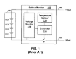
- FIG. 1 is a simplified circuit diagram of a conventional monitor and control circuit for a battery pack including multiple electrochemical cells. Electrochemical cells EC1, EC2, EC3, and EC4 are coupled in series to create a multi-cell battery 160 that can develop a voltage between a positive terminal (+Vbat) 140 and a negative terminal (-Vbat) 150.
- a battery monitor 100 is coupled to the positive terminal 140 and negative terminal 150 to determine whether the multi-cell battery 160 is within a desired voltage range during, for example, charging and discharging.
- a temperature sensor 120 is included to determine if the multi-cell battery 160 is in an acceptable temperature range.
- a controller 130 uses outputs from the temperature sensor 120 and voltage monitor 110 to determine whether to disconnect or connect the multi-cell battery 160 from the negative terminal 150 using switch S1.
- this conventional monitor and control circuit only operates on the multi-cell battery as a whole and doesn't give information or control at the individual electrochemical cell level.
- Embodiments of the present invention comprise apparatuses and methods to improve the overall safety and reliability of electrochemical cells arrayed together by monitoring and controlling the electrochemical cells at a cell level, a sub-array level, or a combination thereof.
- An embodiment of the invention includes a battery sub-array comprising a sub-array electrochemical cell configured for coupling with other sub-array electrochemical cells to form a multi-cell battery.
- a temperature sensor is configured for disposition in a holder for the sub-array electrochemical cell and proximate the sub-array electrochemical cell.
- a bypass switch is operably coupled to switch a first holder terminal to either a second holder terminal or a cell terminal of the sub-array electrochemical cell.
- Monitor and control circuitry is operably coupled to the sub-array electrochemical cell, the bypass switch, and the temperature sensor.
- the monitor and control circuitry is configured for monitoring a temperature of the sub-array electrochemical cell and, responsive to the monitoring, selectively opening the bypass switch to couple the electrochemical cell between the first holder terminal and the second holder terminal or selectively closing the bypass switch to bypass the electrochemical cell.
- Another embodiment of the invention includes a multi-cell battery comprising two or more electrochemical cell circuits operably coupled to form the multi-cell battery.
- Each of the two or more electrochemical cell circuits includes a single electrochemical cell, a bypass switch operably coupled to switch a first holder terminal to either a second holder terminal or a cell terminal of the single electrochemical cell, and monitor and control circuitry operably coupled to the single electrochemical cell and the bypass switch.
- the monitor and control circuitry is configured for monitoring a voltage across the single electrochemical cell and selectively operating the bypass switch to connect or disconnect the cell terminal from the second holder terminal responsive to the monitoring.
- Another embodiment of the invention comprises a monitor and control method including monitoring at least one of a temperature of an electrochemical cell and a voltage across the electrochemical cell and coupling a first terminal of the electrochemical cell to a first terminal of a holder for the electrochemical cell. Responsive to the monitoring, the method also includes selectively coupling a second terminal of the holder either to a second terminal of the electrochemical cell or to the first terminal of the holder.
- Yet another embodiment of the invention comprises a monitoring and control method including monitoring at least one of a temperature of an electrochemical cell and a voltage across the electrochemical cell and electrically coupling terminals of the electrochemical cell to corresponding terminals of a holder for the electrochemical cell. Responsive to the monitoring, the method also includes selectively bypassing the electrochemical cell by coupling the terminals of the holder together and decoupling at least one terminal of the electrochemical cell from a corresponding terminal of the holder.
- Yet another embodiment of the invention comprises a holder for an electrochemical cell including a housing and a thermal container encompassing a substantial portion of the housing.
- the housing includes a first serial side, a second serial side opposite from the first serial side, a first parallel side, and a second parallel side opposite from the first parallel side.
- a cell cavity within the housing is configured to receive the electrochemical cell
- a sensor cavity within the housing is configured to receive a temperature sensor
- a circuit cavity within the housing configured to receive circuitry for monitoring and controlling the electrochemical cell.
- a positive terminal on the first serial side is configured for operable coupling to the electrochemical cell and a negative terminal on the second serial side is configured for operable coupling to the electrochemical cell.
- the housing is configured for mechanical and electrical engagement with a first other electrochemical cell holder on the first serial side and mechanical and electrical engagement with a second other electrochemical cell holder on the first serial side.
- a flowchart may describe operational acts as a sequential process, many of these acts can be performed in another sequence, in parallel, or substantially concurrently.
- the order of the acts may be re-arranged.
- a process may correspond to a method, a function, a procedure, a subroutine, a subprogram, etc.
- the methods disclosed herein may be implemented in hardware, software, or both. If implemented in software, the functions may be stored or transmitted as one or more instructions or code on a computer-readable medium.
- Computer-readable media includes both computer storage media and communication media including any medium that facilitates transfer of a computer program from one place to another.
- any reference to an element herein using a designation such as “first,” “second,” and so forth does not limit the quantity or order of those elements, unless such limitation is explicitly stated. Rather, these designations may be used herein as a convenient method of distinguishing between two or more elements or instances of an element. Thus, a reference to first and second elements does not mean that only two elements may be employed there or that the first element must precede the second element in some manner. Also, unless stated otherwise a set of elements may comprise one or more elements.
- Elements described herein may include multiple instances of the same element. These elements may be generically indicated by a numerical designator (e.g. 110) and specifically indicated by the numerical indicator followed by an alphabetic designator (e.g., 110A) or a numeric indicator preceded by a "dash" (e.g., 110-1).
- a numerical designator e.g. 110
- an alphabetic designator e.g., 110A
- a numeric indicator preceded by a "dash” e.g., 110-1
- element number indicators begin with the number of the drawing on which the elements are introduced or most fully discussed. Thus, for example, element identifiers on a FIG. 1 will be mostly in the numerical format 1xx and elements on a FIG. 4 will be mostly in the numerical format 4xx.
- designators for the circuit elements begin with an element type designator (e.g., R, C, M, EC, respectively) followed by a numeric indicator.
- element type designator e.g., R, C, M, EC, respectively
- Power sources such as, for example VDD and VCC as well as ground voltages may be generically indicated. When appropriate, these power signals may be described in detail. In other cases, the power signals may not be described as it would be apparent to a person of ordinary skill in the art which power signal should be used.
- Embodiments of the present invention comprise apparatuses and methods for monitoring and controlling electrochemical cells configured to be arrayed in serial, parallel, or a combination thereof to form a multi-cell battery with a desired voltage and current capability.
- a single electrochemical cell refers to one electrochemical cell, which may include accompanying monitor and control circuitry.
- an electrochemical cell or “the electrochemical cell,” it should be interpreted as a single electrochemical cell unless otherwise stated.
- a “sub-array electrochemical cell” or a “battery sub-array” refers to one or more electrochemical cells connected in serial, parallel, or a combination thereof with accompanying monitor and control circuitry wherein the sub-array of electrochemical cells is configured and intended for electrical and mechanical coupling to similarly configured sub-arrays of electrochemical cells to form a multi-cell battery.
- a multi-cell battery refers to a battery including a plurality of single electrochemical cells operably coupled together or a battery including a plurality of sub-array electrochemical cells operably coupled together.
- FIGS. 2A and 2B are simplified circuit diagrams of a battery sub-array 200 including monitor and control circuitry 250 for one or more electrochemical cells according to embodiments of the present invention.
- An electrochemical cell EC1 is coupled between a positive terminal (Vcell+) 220 and a negative terminal (Vcell-) 210.
- a bypass switch SW1 is coupled to the positive terminal 220 and configured for switching between an A position and a B position.
- the A position is referred to as an open position for the bypass switch SW1 and the B position is referred to as a closed position for the bypass switch SW1.
- the bypass switch SW1 When in the closed position, the bypass switch SW1 connects the positive terminal 220 to the negative terminal 210, effectively bypassing the electrochemical cell EC1.
- the bypass switch SW1 connects a positive terminal of the electrochemical cell EC1 to the positive terminal 220 of the battery sub-array 200, effectively connecting the electrochemical cell EC1 between the positive terminal 220 and the negative terminal 210.
- multiple electrochemical cells may be used.
- an optional second electrochemical cell EC2 is shown in series with the electrochemical cell EC1. While not show, the two electrochemical cells may also be connected in parallel.
- the battery sub-array 200 may include four electrochemical cells connected in a 2x2 array with two sets of electrochemical cells connected in parallel and each set includes two electrochemical cells in series.
- the monitor and control circuitry 250 may be coupled to a positive terminal 222 of the electrochemical cell EC1and a negative terminal 212 of the electrochemical cell EC1.
- a temperature sensor 240 may be included and disposed in proximity to the electrochemical cell EC1 to sense its temperature. The temperature sensor 240, if included, is operably coupled to the monitor and control circuitry 250.
- the monitor and control circuitry 250 uses voltage information from the positive terminal 222 and the negative terminal 212, temperature information, or a combination thereof, to determine whether the electrochemical cell EC1 is operating within acceptable parameters and based on that determination operates the bypass switch SW1.
- Some embodiments may include a communication bus 290 coupled to the monitor and control circuitry 250.
- the communication bus 290 may be used to convey information about the battery sub-array 200 to an external controller. As non-limiting examples, such information may include serial numbers of the electrochemical cell EC1 and battery sub-array 200, voltage information, temperature information, maintenance information, and historical information about voltage, temperature, and operation of the bypass switch SW1.
- the communication bus 290 may also convey information to the battery sub-array 200, such as, for example, voltage and temperature parameters for acceptable operation, as is explained more fully below.
- the communication bus may be any suitable bus, such as, for example, a military standard 1553 serial communication bus, an RS-422 serial communication bus, or a Universal Serial Bus (USB).
- FIG. 2A illustrates the bypass switch SW1 coupled on the positive terminal 220 side of the battery sub-array 200.
- the bypass switch may be coupled on the negative terminal 210 of the battery sub-array 200 and the negative terminal of the electrochemical cell EC1.
- FIG. 2B illustrates a circuit similar to that of FIG. 2A except using a bypass switch SW2 instead of the bypass switch SW1 of FIG. 2A .
- the double-pole double throw bypass switch SW2 is configured such that in a first position terminal A connects to terminal B and terminal D connects to terminal E. In a second position terminal A connects to terminal C and terminal D connects to terminal F. Thus, in the first position the bypass switch SW2 is closed to connect the positive terminal 220 to the negative terminal 210, effectively bypassing the electrochemical cell EC1. When in the second position the bypass switch SW2 is to connect the positive terminal of the electrochemical cell EC1 to the positive terminal 220 of the battery sub-array 200, effectively connecting the electrochemical cell EC1 between the positive terminal 220 and the negative terminal 210.
- the electrochemical cell EC1 may be a Li-Ion cell.
- other types of electrochemical cells such as, for example, lithium metal, lithium polymer, nickel cadmium (NiCd), nickel metal hydride (NiMH), and lead acid cells.
- the battery sub-array 200 is configured to be coupled with other battery sub-arrays 200 to form a multi-cell battery.
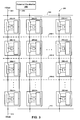
- FIG. 3 is a simplified circuit diagram of a multi-cell battery 300 as an array of the battery sub-arrays 200 illustrated in FIG. 2 .
- the battery sub-arrays 200 are numbered with index values for the position within the array. For example, the battery sub-array 200-23 is in the second column and the third row.
- the entire multi-cell battery 300 includes "m" columns and "n" rows. In FIG. 2 , columns are coupled in series to develop a larger voltage between a negative battery terminal 310 and a positive battery terminal 320.
- each individual battery sub-array 200 includes a Li-Ion electrochemical cell EC1 with a nominal voltage of about 3.6 volts and the array includes 5 rows, each column would deliver about 18 volts.
- the columns are coupled together in parallel with each of the first row's positive terminals connected to the positive battery terminal 320 and each of the n th row's negative terminals coupled to the negative battery terminal 310.
- the intermediate connections between rows may be connected, as indicated by the dashed lines for parallel connections 350-1, 350-2, and 350-3.
- such intermediate parallel connections may be useful for balancing voltages across the parallel connections of battery sub-arrays 200 for any particular row.
- An external controller 390 may be coupled to the communication bus 290 and the communication bus 290 connections for each of the battery sub-arrays 200 may be coupled together.
- the external controller 390 may be a controller for the multi-cell battery 300 or may be a controller for the device being powered by the multi-cell battery 300.
- All of the battery sub-arrays 200 are illustrated with the bypass switches SW 1 open except for battery sub-array 200-22. As a result, battery sub-array 200-22 is being bypassed while all of the other battery sub-arrays 200 are connected in the array in their appropriate serial or parallel connections.
- FIGS. 4A and 4B are simplified circuit diagrams of embodiments of the monitor and control circuitry of FIG. 2 .
- a temperature signal (Vtemp) 320 comes from the temperature sensor 240 ( FIG.2 ) and a voltage differential signal 420 indicates a voltage across the electrochemical cell EC 1 .
- a differential amplifier 405 generates the voltage differential signal 420 as a difference between a voltage on the positive terminal 222 of the electrochemical cell EC1and a voltage on the negative terminal 212 of the electrochemical cell EC 1 .
- a maximum voltage comparator 410 compares the voltage differential signal 420 to a reference voltage (Vcell max) indicating a maximum voltage that should be allowed across electrochemical cell EC 1 . If the voltage differential signal 420 exceeds the reference voltage (Vcell max), the maximum voltage comparator 410 will generate a high on its output, otherwise the output will remain low.
- Vcell max a reference voltage
- a minimum voltage comparator 412 compares the voltage differential signal 420 to a reference voltage (Vcell min) indicating a minimum voltage that should be allowed across electrochemical cell EC1. If the voltage differential signal 420 is less than the reference voltage (Vcell min), the minimum voltage comparator 412 will generate a high on its output, otherwise the output will remain low.
- Vcell min a reference voltage
- a maximum temperature comparator 414 compares a temperature signal 430 to a reference voltage (Vtemp max) indicating a maximum temperature that should be allowed for electrochemical cell EC1. If the temperature signal 430 exceeds the reference voltage (Vtemp max), the maximum temperature comparator 414 will generate a high on its output, otherwise the output will remain low.
- Vtemp max a reference voltage
- a minimum temperature comparator 416 compares the temperature signal 430 to a reference voltage (Vtemp min) indicating a minimum temperature that should be allowed across electrochemical cell EC 1 . If the temperature signal 430 is less than the reference voltage (Vtemp min), the minimum temperature comparator 416 will generate a high on its output, otherwise the output will remain low.
- Vtemp min a reference voltage
- An OR-gate 440 (or possibly a wired-OR connection) generates a high on a switch control signal 450 if an output of any of the comparators (410, 412, 414, and 416) is high.
- the bypass switch SW1 is illustrated as a p-channel Metal-Oxide Field-Effect Transistor (MOSFET) M1 and an n-channel MOSFET M2. If the switch control signal 450 is high, the n-channel MOSFET M2 will be on and the p-channel MOSFET M1 will be off, effectively bypassing the electrochemical cell EC1. If the switch control signal 450 is low, the p-channel MOSFET M1 will be on and the n-channel MOSFET M2 will be off, effectively coupling the electrochemical cell EC1 between the positive terminal 220 and the negative terminal 210.
- MOSFET Metal-Oxide Field-Effect Transistor
- bypass switch SW 1 may be used for many other circuit configurations.
- relays, bipolar transistor, and bipolar junction field-effect transistors may also be used.
- other configurations may be used such as both M 1 and M 2 being n-channel MOSFETs, both M 1 and M 2 being p-channel MOSFETs, and both M 1 and M 2 being pass-gates configured as a p-channel and n-channel MOSFETs in parallel.
- FIG. 4B illustrates another embodiment of monitor and control circuitry 250B as a controller 250B.
- This controller may be a circuit such as, for example, a Field Programmable Gate Array (FPGA), and Application Specific Integrated Circuit (ASIC), a microcontroller, or a microprocessor.
- the controller 250B may be coupled to a temperature signal 460 from the temperature sensor 240 ( FIG. 2 ), the negative terminal 210, the positive terminal 220, and a positive cell terminal 480 from the electrochemical cell EC1.
- the controller 250B samples the analog voltages from these signals and uses one or more analog-to-digital converters to create digital values for each of the signals.
- the controller can, therefore, generate a digital value for the temperature, the voltage on the positive terminal 220, the voltage on the negative terminal 210, and the voltage on the positive cell terminal 480.
- the controller 250B operates the switch control signal 450 to control the bypass switch SW1 in a manner similar to that discussed above with respect to FIG. 4A .
- FIG. 5 is a simplified flow diagram illustrating monitoring of voltage levels of an electrochemical cell or sub-array.
- Operation block 510 indicates that the voltages across the electrochemical cell EC1 are measured.
- Decision block 520 indicates a test to determine if the cell voltage is increasing, which generally indicates that the electrochemical cell EC 1 is being charged. If so, decision block 530 indicates a test to see if the cell voltage is greater than a predetermined maximum voltage. If not, operation block 540 indicates that the charging may continue and the bypass switch SW1 remains open. The process then loops back to gather new voltage samples and repeat the process.
- operation block 570 indicates that the bypass switch SW1 is closed to bypass the electrochemical cell EC1.
- the process may stop there and the bypass switch SW1 may remain closed permanently or until reset by a command from the external controller 390 ( FIG. 3 ).
- operation block 580 indicates that the process may wait for a delay time, then operation block 590 opens the bypass switch SW1 to connect the electrochemical cell EC1 to the terminals and the process repeats.
- decision block 550 tests to see if the cell voltage is below a predetermined minimum voltage. If not, operation block 560 indicates that the discharge process continues and the process loops back to gather new voltage samples and repeat the process. If the cell voltage is less than the predetermined minimum voltage, the process continues at operation block 570 as discussed above.
- FIG. 6 is a simplified flow diagram illustrating monitoring of temperature of an electrochemical cell or sub-array.
- Operation block 605 indicates that the temperature near the electrochemical cell EC1 is sampled.
- Decision block 610 indicates a test to determine if the cell temperature is greater than a predetermined maximum temperature. If so, operation block 640 indicates that the bypass switch SW1 is closed to bypass the electrochemical cell EC1.
- decision block 620 indicates a test to determine if the cell temperature is less than a predetermined minimum temperature. If so, operation block 640 indicates that the bypass switch SW1 is closed to bypass the electrochemical cell EC1. If not, decision block 630 indicates a test to determine if a rate of change for the temperature is greater than a predetermined rate threshold. If so, operation block 640 indicates that the bypass switch SW1 is closed to bypass the electrochemical cell EC1. If not, the bypass switch is open at operation block 650 (if not already open) to connect the electrochemical cell EC1 to the terminals and the process repeats.
- a suitable rate of change may depend on environmental conditions and type of electrochemical cell EC1.
- the predetermined rate threshold may be about 2.5 degrees C/second.
- FIGS. 5 and 6 may run in parallel or in serial and may run in a continuous loop or may be set to trigger at specific intervals, such as, for example, at one-second intervals.
- a predetermined maximum temperature may be about 50 degrees C and a predetermined minimum temperature may be about -10 degrees C.
- a predetermined maximum voltage may be about 4.2 volts and a predetermined minimum voltage may be about 2.8 volts.
- FIG. 7 is a simplified isometric view of a holder 700 for the electrochemical cell EC1 ( FIGS. 8 and 9 ) and monitor and control circuitry 250 ( FIGS. 8 and 9 ) according to an embodiment of the present invention.
- FIG. 8 is a top cross-section view of the holder 700 of FIG. 7.
- FIG. 9 is a side cross-section view of the holder 700 of FIG. 7.
- FIGS. 7, 8, and 9 are discussed together.
- the holder 700 includes a housing 710 with a first serial side 712, a second serial side 714 opposite from the first serial side 712, a first parallel side 716, and a second parallel side 718 opposite from the first parallel side 716.
- the serial sides (712 and 714) refer to sides of the holder that have terminal connections for placing the battery sub-arrays 200 ( FIG. 2 ) in series connection when the holders 700 are abutted with serial sides together.
- the parallel sides (716 and 718) refer to sides of the holder that have terminal connections for placing the battery sub-arrays 200 ( FIG. 2 ) in parallel connection when holders 700 are abutted with parallel sides together.
- First protrusions 722 on the first serial side 712 extend from the holder 700 at or near the top and bottom of the holder 700.
- Second protrusions 724 on the second serial side 714 extend from the holder 700 at or near the top and bottom of the holder 700.
- Third protrusions 726 on the first parallel side 716 extend from the holder 700 at or near the top and bottom of the holder 700.
- fourth protrusions 728 extend from the second parallel side 718 of the holder 700 at or near the top and bottom of the holder 700.
- the protrusions may be configured such that they will mesh with protrusions from an opposing side of another holder abutted against the holder 700.
- first protrusions 722 on the first serial side 712 of one holder may mesh with second protrusions 724 on the second serial side 714 of another holder.
- third protrusions 726 on the first parallel side 716 of one holder may mesh with fourth protrusions 728 on the second parallel side 718 of another holder.
- the protrusions may be configured such that holders can only be abutted in proper directions such as parallel side to parallel side and serial side to serial side.
- a cell cavity 740 within the housing 710 is configured to receive the electrochemical cell EC1.
- a sensor cavity 760 within the housing 710 is configured to receive the temperature sensor 240, and a circuit cavity 750 within the housing 710 is configured to receive the monitor and control circuitry 250.
- Positive terminals 220 may be located at various locations on the various sides of the holder 700 as illustrated in FIGS. 7, 8, and 9 .
- negative terminals 210 may be located at various locations on the various sides of the holder 700 as illustrated in FIGS. 7, 8, and 9 .
- the terminals (210 and 220) may be positioned slightly recessed in terminal cavities 790 such that when the holders are abutted, electrical connections are not necessarily formed where the terminals line up.
- the positive terminals 220 may be electrically coupled to the positive cell terminal by coupling strap 222 and the negative terminals 210 may be electrically coupled to the negative terminal 210 by coupling strap 224.
- a thermal container 730 may encompass a substantial portion of the housing 710.
- the substantial covering may include all sides of the housing except for opening for exposing the terminals (210 and 220).
- the thermal container 730 may not cover the top and bottom sides of the holder 700.
- the thermal container 730 may include openings for access to the various cavities (740, 750 and 760).
- the thermal container may be configured to thermally spread heat more evenly around the container as well as shield heat of one holder 700 from an abutting holder 700.
- the thermal container may be formed from a flexible graphite material such as eGRAF® SPREADSHIELDTM from GrafTech International Ltd. of Parma, Ohio.
- the housing 710 may be aluminum that is machined to include the various cavities (74, 750, 760, and 790) and various protrusions (722, 724, 726, and 728).
- the housing 710 may be formed of a suitable plastic material.
- the protrusions may be configured as part of the housing 710 and in other embodiments with a suitable thermal container 730, the protrusions may be configured as part of the thermal container 730.
- the holder 700 may have a height of about 7.62 centimeters (3 inches) and side-to-side dimensions of about 3.175 centimeters by 3.175 centimeters (1.25 inches by 1.25 inches).
- FIG. 10 is a top cross-section view of a holder 700 similar to that of FIG. 7 except the holder 700 of FIG. 10 is configured for a sub-array of two electrochemical cells EC 1 and EC 2 placed in respective cell cavities 740-1 and 740-2.
- FIG. 11 is a top view of three holders 700 mechanically and electrically coupled to form a multi-cell battery of three electrochemical cells (EC1, EC2, and EC3) in series.
- connection plugs 910 are placed in appropriate terminal cavities 790 ( FIG. 7 ) such that a positive terminal 220 for the holder of electrochemical cell EC1 connects to a negative terminal 210 for the electrochemical cell EC2 and a positive terminal 220 for the holder of electrochemical cell EC2 connects to a negative terminal 210 for the electrochemical cell EC3.
- the connection plugs 910 fit in the terminal cavities 790 such that the connection plugs 910 are coplanar with, or slightly protrude from, the side of the holder. As a result, when the holders 700 are properly mechanically abutted, proper electrical connections are made while the other terminals remain unconnected.
- FIG. 12 is a top view of four holders 700 mechanically and electrically coupled to form a multi-cell battery of four electrochemical cells in series and in parallel.
- the positive terminals 220 and the negative terminals 210 are configured for selective retraction such that the terminal is retracted within a terminal cavity 790 of the holder 700 so it will not electrically connect to a corresponding terminal of an adjacent holder.
- the terminals can also be extended such that they are coplanar with, or slightly protruding from, an exterior surface of the holder 700 so it will electrically connect with a corresponding terminal of an adjacent holder.
- the selective retraction of terminals in this embodiment may be configured as a catch and spring mechanism so that the terminal is biased to the extended position by a spring and held in the retracted position by a catch.
- the selective retraction may include a screw mechanism that rotates one direction to extend the terminal and rotates another direction to retract the terminal. The screw mechanism may be more appropriate for some embodiments that may be exposed to harsh environments, such as, for example, vibration and shock.
- connection plugs 910 create the parallel electrical coupling between positive terminals of electrochemical cell EC2 and electrochemical cell EC4. Also, connection plugs 910 create the parallel electrical coupling between negative terminals of electrochemical cell EC1 and electrochemical cell EC3.
Landscapes
- Chemical & Material Sciences (AREA)
- Chemical Kinetics & Catalysis (AREA)
- Electrochemistry (AREA)
- General Chemical & Material Sciences (AREA)
- Engineering & Computer Science (AREA)
- Manufacturing & Machinery (AREA)
- Power Engineering (AREA)
- Physics & Mathematics (AREA)
- General Physics & Mathematics (AREA)
- Microelectronics & Electronic Packaging (AREA)
- Secondary Cells (AREA)
- Charge And Discharge Circuits For Batteries Or The Like (AREA)
Applications Claiming Priority (1)
| Application Number | Priority Date | Filing Date | Title |
|---|---|---|---|
| US12/904,830 US8470464B2 (en) | 2010-10-14 | 2010-10-14 | Methods and apparatuses for electrochemical cell monitoring and control |
Publications (3)
| Publication Number | Publication Date |
|---|---|
| EP2442384A2 true EP2442384A2 (de) | 2012-04-18 |
| EP2442384A3 EP2442384A3 (de) | 2012-07-25 |
| EP2442384B1 EP2442384B1 (de) | 2014-08-06 |
Family
ID=44789355
Family Applications (1)
| Application Number | Title | Priority Date | Filing Date |
|---|---|---|---|
| EP20110185056 Active EP2442384B1 (de) | 2010-10-14 | 2011-10-13 | Verfahren und Vorrichtungen zur Überwachung und Steuerung elektrochemischer Zellen |
Country Status (2)
| Country | Link |
|---|---|
| US (1) | US8470464B2 (de) |
| EP (1) | EP2442384B1 (de) |
Cited By (8)
| Publication number | Priority date | Publication date | Assignee | Title |
|---|---|---|---|---|
| DE102013007099A1 (de) | 2013-04-24 | 2014-10-30 | Daimler Ag | Schaltungsanordnung zum Entkoppeln einer ersten von einer zweiten Zelle einer Batterie |
| DE102013007172A1 (de) | 2013-04-24 | 2014-10-30 | Daimler Ag | Batteriezellenanordnung |
| WO2015062695A1 (de) * | 2013-11-02 | 2015-05-07 | Daimler Ag | Batterie mit einer vielzahl von batterieeinzelzellen |
| WO2016131806A1 (de) * | 2015-02-18 | 2016-08-25 | Audi Ag | Verfahren zum fertigen einer batterie, batterie und kraftfahrzeug |
| GB2569947A (en) * | 2017-12-28 | 2019-07-10 | Moog Unna Gmbh | Power supply arrangement with by-pass diodes |
| DE102018221813A1 (de) * | 2018-12-14 | 2020-06-18 | Robert Bosch Gmbh | Verfahren zum Überwachen und Steuern einer Batteriezelleneinheit |
| CN115116555A (zh) * | 2022-06-29 | 2022-09-27 | 上海玫克生储能科技有限公司 | 基于打靶法的电化学模型的电场解耦方法及装置 |
| EP4175007A1 (de) * | 2021-10-27 | 2023-05-03 | Huawei Digital Power Technologies Co., Ltd. | Sicherheitserkennungsverfahren für batteriemodul, batteriemodul, batteriepack und energiespeichersystem |
Families Citing this family (28)
| Publication number | Priority date | Publication date | Assignee | Title |
|---|---|---|---|---|
| CN103376413A (zh) * | 2012-04-20 | 2013-10-30 | 凹凸电子(武汉)有限公司 | 电池测试系统及控制电池测试系统的方法 |
| US20140008985A1 (en) * | 2012-07-06 | 2014-01-09 | Robert Bosh Gmbh | Method and system for control of energy storage devices |
| US10003062B2 (en) * | 2012-09-14 | 2018-06-19 | Lenovo Enterprise Solutions (Singapore) Pte. Ltd. | Modular battery cover |
| US9728017B2 (en) * | 2013-03-01 | 2017-08-08 | Yves Paquin | Electronic door access control system |
| DE102013225250A1 (de) * | 2013-12-09 | 2015-06-11 | Robert Bosch Gmbh | Batteriesystem |
| US20150372527A1 (en) * | 2014-06-23 | 2015-12-24 | Infineon Technologies Ag | Battery thermal acceleration mechanism |
| US9627723B2 (en) * | 2014-07-30 | 2017-04-18 | Ec Power, Llc | Operation of electrochemical energy systems |
| CN104362688A (zh) * | 2014-10-27 | 2015-02-18 | 合肥创源车辆控制技术有限公司 | 一种电池组冗余连接方法 |
| TWI568122B (zh) | 2015-11-09 | 2017-01-21 | 財團法人工業技術研究院 | 電池系統與其控制方法 |
| EP3398239A1 (de) * | 2015-12-29 | 2018-11-07 | Vito NV | Vorrichtung und verfahren zur neukonfiguration einer wiederaufladbaren energiespeichervorrichtung in getrennte batterieverbindungsstränge |
| CN105576765B (zh) * | 2016-02-04 | 2019-08-30 | 惠州市蓝微新源技术有限公司 | 一种多节电池的电压采集电路 |
| TWI649939B (zh) | 2017-07-07 | 2019-02-01 | 財團法人工業技術研究院 | 電源裝置運作方法、電源裝置及電源裝置管理系統 |
| WO2019023672A1 (en) * | 2017-07-28 | 2019-01-31 | Northstar Battery Company, Llc | WIRELESS ACTIVATED MONOBLOC |
| US10684330B2 (en) | 2017-07-28 | 2020-06-16 | Northstar Battery Company, Llc | Systems and methods for detecting thermal runaway of a battery |
| US20200287394A1 (en) * | 2017-09-22 | 2020-09-10 | Urban Electric Power Inc. | A system to charge cells assembled into a battery |
| US10935605B2 (en) * | 2018-05-03 | 2021-03-02 | Ford Global Technologies, Llc | Battery array activating assembly and method |
| WO2020047663A1 (en) | 2018-09-05 | 2020-03-12 | Dpm Technologies Inc. | Systems and methods for intelligent energy storage and provisioning using an energy storage control system |
| JP7096193B2 (ja) * | 2019-04-04 | 2022-07-05 | 矢崎総業株式会社 | 電池制御ユニット及び電池システム |
| WO2020215154A1 (en) | 2019-04-23 | 2020-10-29 | Dpm Technologies Inc. | Fault tolerant rotating electric machine |
| JP7051776B2 (ja) * | 2019-09-30 | 2022-04-11 | 矢崎総業株式会社 | 電池制御ユニットおよび電池システム |
| BR112022017303A2 (pt) * | 2020-04-10 | 2022-12-13 | Electric Power Systems Inc | Sistemas de módulos de bateria interconectados, montagens e métodos |
| JP7157101B2 (ja) * | 2020-06-19 | 2022-10-19 | 矢崎総業株式会社 | 電池制御ユニット及び電池システム |
| JP7160862B2 (ja) * | 2020-06-19 | 2022-10-25 | 矢崎総業株式会社 | 電池制御ユニット及び電池システム |
| WO2022232904A1 (en) * | 2021-05-04 | 2022-11-10 | Exro Technologies Inc. | Battery control systems and methods |
| DE102021111866A1 (de) | 2021-05-06 | 2022-11-10 | instagrid GmbH | Energieversorgungssystem mit Batteriemodulen sowie Verfahren zum Betrieb eines Energieversorgungssystems |
| CN117337545A (zh) | 2021-05-13 | 2024-01-02 | Exro技术公司 | 驱动多相电机的线圈的方法及装置 |
| CA3223051A1 (en) | 2021-07-08 | 2023-01-12 | Eric HUSTEDT | Dynamically reconfigurable power converter utilizing windings of electrical machine |
| US20230170544A1 (en) * | 2021-11-29 | 2023-06-01 | Medtronic, Inc. | Electrochemical cell heat shunt |
Family Cites Families (17)
| Publication number | Priority date | Publication date | Assignee | Title |
|---|---|---|---|---|
| AU680210B2 (en) | 1993-01-29 | 1997-07-24 | Canon Kabushiki Kaisha | Electric power accumulating apparatus and electric power system |
| US5670861A (en) | 1995-01-17 | 1997-09-23 | Norvik Tractions Inc. | Battery energy monitoring circuits |
| US5939861A (en) | 1996-05-24 | 1999-08-17 | Hino Jidosha Kogyo Kabushiki Kaisha | Control system for on-vehicle battery |
| US6025696A (en) * | 1998-03-27 | 2000-02-15 | Space Systems/Loral, Inc. | Battery cell bypass module |
| JP3740323B2 (ja) * | 1998-07-31 | 2006-02-01 | キヤノン株式会社 | 二次電池の充電方法及びその装置 |
| US6417646B1 (en) * | 2001-05-22 | 2002-07-09 | Honeywell International Inc. | Circuit for monitoring cells of a multi-cell battery during charge |
| US7157882B2 (en) | 2002-11-22 | 2007-01-02 | Milwaukee Electric Tool Corporation | Method and system for battery protection employing a selectively-actuated switch |
| CN1864300B (zh) | 2003-10-03 | 2010-12-15 | 布莱克和戴克公司 | 无绳电动工具系统的电池组的放电控制方法、被适配来提供过放电保护和放电控制的无绳电动工具系统和电池组 |
| WO2005038952A2 (en) | 2003-10-14 | 2005-04-28 | Black & Decker Inc. | Protection methods, protection circuits and protective devices for secondary batteries, a power tool, charger and battery pack adapted to provide protection against fault conditions in the battery pack |
| JP4078553B2 (ja) * | 2003-10-21 | 2008-04-23 | 新神戸電機株式会社 | 車両用リチウム電池モジュール |
| KR100584404B1 (ko) | 2004-11-11 | 2006-05-26 | 삼성전자주식회사 | 이동 통신 단말기의 배터리 장치 및 그 운용 방법 |
| EP1780867B1 (de) | 2005-10-28 | 2016-11-30 | Black & Decker Inc. | Akkupack für schnurlose Elektrowerkzeuge |
| US7576545B2 (en) | 2006-10-18 | 2009-08-18 | Honeywell International Inc. | Lithium-ion battery prognostic testing and process |
| DE102007049528B4 (de) | 2007-10-15 | 2009-06-25 | Panasonic Electronic Devices Europe Gmbh | Verfahren und Vorrichtung zur Messung von Zellenspannungen in einer Mehrzahl von in Reihe geschalteten Akkumulatorzellen |
| US8212522B2 (en) | 2008-02-12 | 2012-07-03 | Leah M. Piatkowski, legal representative | Energy storage module |
| US8253383B2 (en) | 2009-02-05 | 2012-08-28 | O2Micro Inc | Circuits and methods for monitoring multi-cell battery packs |
| US20100213897A1 (en) | 2009-02-23 | 2010-08-26 | Lawrence Tze-Leung Tse | Battery-Cell Converter Management Systems |
-
2010
- 2010-10-14 US US12/904,830 patent/US8470464B2/en active Active
-
2011
- 2011-10-13 EP EP20110185056 patent/EP2442384B1/de active Active
Cited By (10)
| Publication number | Priority date | Publication date | Assignee | Title |
|---|---|---|---|---|
| DE102013007099A1 (de) | 2013-04-24 | 2014-10-30 | Daimler Ag | Schaltungsanordnung zum Entkoppeln einer ersten von einer zweiten Zelle einer Batterie |
| DE102013007172A1 (de) | 2013-04-24 | 2014-10-30 | Daimler Ag | Batteriezellenanordnung |
| WO2015062695A1 (de) * | 2013-11-02 | 2015-05-07 | Daimler Ag | Batterie mit einer vielzahl von batterieeinzelzellen |
| WO2016131806A1 (de) * | 2015-02-18 | 2016-08-25 | Audi Ag | Verfahren zum fertigen einer batterie, batterie und kraftfahrzeug |
| CN107249924A (zh) * | 2015-02-18 | 2017-10-13 | 奥迪股份公司 | 用于制造电池的方法、电池和机动车 |
| US10637036B2 (en) | 2015-02-18 | 2020-04-28 | Audi Ag | Method for manufacturing a battery, battery, and motor vehicle |
| GB2569947A (en) * | 2017-12-28 | 2019-07-10 | Moog Unna Gmbh | Power supply arrangement with by-pass diodes |
| DE102018221813A1 (de) * | 2018-12-14 | 2020-06-18 | Robert Bosch Gmbh | Verfahren zum Überwachen und Steuern einer Batteriezelleneinheit |
| EP4175007A1 (de) * | 2021-10-27 | 2023-05-03 | Huawei Digital Power Technologies Co., Ltd. | Sicherheitserkennungsverfahren für batteriemodul, batteriemodul, batteriepack und energiespeichersystem |
| CN115116555A (zh) * | 2022-06-29 | 2022-09-27 | 上海玫克生储能科技有限公司 | 基于打靶法的电化学模型的电场解耦方法及装置 |
Also Published As
| Publication number | Publication date |
|---|---|
| US20120094150A1 (en) | 2012-04-19 |
| US8470464B2 (en) | 2013-06-25 |
| EP2442384A3 (de) | 2012-07-25 |
| EP2442384B1 (de) | 2014-08-06 |
Similar Documents
| Publication | Publication Date | Title |
|---|---|---|
| EP2442384B1 (de) | Verfahren und Vorrichtungen zur Überwachung und Steuerung elektrochemischer Zellen | |
| EP3618221B1 (de) | Vorrichtung zum batterieausgleich und batteriepack damit | |
| ES3002907T3 (en) | Apparatus and method for detecting defect of battery pack | |
| Garche et al. | Battery management systems (BMS) for increasing battery life time | |
| US8198862B2 (en) | Battery pack with balancing management | |
| KR102028170B1 (ko) | 셀 밸런싱 회로 및 이를 구비한 배터리 팩 | |
| US10873201B2 (en) | Battery management apparatus and method for protecting a lithium iron phosphate cell from over-voltage using the same | |
| KR20060011966A (ko) | 배터리 셀 열 보호 및 배터리 팩 과충전/부족충전 보호를위한 겸용 서미스터 | |
| US11070068B2 (en) | Battery pack and method for discharging the same after a fault event | |
| US20130293006A1 (en) | Battery balancing system and battery balancing method using the same | |
| EP3974850B1 (de) | Vorrichtung und verfahren zur diagnose eines parallelbatterierelais | |
| KR20110134751A (ko) | 배터리 팩 및 이의 제어 방법 | |
| JP5724227B2 (ja) | 電池パック及びそれを用いた電動工具 | |
| US9564764B2 (en) | Apparatus and method for battery management with malfunction prevention algorithm | |
| KR101630411B1 (ko) | 배터리 팩 관리 장치 및 이를 포함하는 배터리 팩 | |
| EP3633782A1 (de) | Batterieverwaltungssystem und -verfahren zur optimierung des inneren widerstands einer batterie | |
| EP3499678B1 (de) | Batteriepack | |
| KR20070101496A (ko) | 다병렬 및 다직렬 리튬 2차전지 팩의 충방전 모니터링시스템 | |
| JP4890110B2 (ja) | 電池管理システム | |
| KR102765888B1 (ko) | 배터리 온도 감시 장치 | |
| US20240258817A1 (en) | Battery Charge/Discharge Control Device and Battery Management Device | |
| EP4040175B1 (de) | Batteriesystem und batteriepack | |
| KR101578707B1 (ko) | 배터리 팩 및 이의 제어 방법 | |
| KR20190091037A (ko) | 드론용 리튬 배터리의 과충전, 수명단축 및 폭발 방지 장치 및 그 방법 | |
| US20130265059A1 (en) | System and Method for Verifying a Reference Voltage for Battery Cell Monitoring |
Legal Events
| Date | Code | Title | Description |
|---|---|---|---|
| PUAI | Public reference made under article 153(3) epc to a published international application that has entered the european phase |
Free format text: ORIGINAL CODE: 0009012 |
|
| AK | Designated contracting states |
Kind code of ref document: A2 Designated state(s): AL AT BE BG CH CY CZ DE DK EE ES FI FR GB GR HR HU IE IS IT LI LT LU LV MC MK MT NL NO PL PT RO RS SE SI SK SM TR |
|
| AX | Request for extension of the european patent |
Extension state: BA ME |
|
| PUAL | Search report despatched |
Free format text: ORIGINAL CODE: 0009013 |
|
| RIC1 | Information provided on ipc code assigned before grant |
Ipc: H01M 2/20 20060101ALI20120612BHEP Ipc: H02J 7/00 20060101ALI20120612BHEP Ipc: H01M 2/10 20060101AFI20120612BHEP Ipc: H01M 10/50 20060101ALI20120612BHEP Ipc: G01R 31/36 20060101ALI20120612BHEP Ipc: H01M 10/48 20060101ALI20120612BHEP |
|
| AK | Designated contracting states |
Kind code of ref document: A3 Designated state(s): AL AT BE BG CH CY CZ DE DK EE ES FI FR GB GR HR HU IE IS IT LI LT LU LV MC MK MT NL NO PL PT RO RS SE SI SK SM TR |
|
| AX | Request for extension of the european patent |
Extension state: BA ME |
|
| 17P | Request for examination filed |
Effective date: 20121220 |
|
| 17Q | First examination report despatched |
Effective date: 20130705 |
|
| REG | Reference to a national code |
Ref country code: DE Ref legal event code: R079 Ref document number: 602011008847 Country of ref document: DE Free format text: PREVIOUS MAIN CLASS: H01M0002100000 Ipc: H01M0010600000 |
|
| RIC1 | Information provided on ipc code assigned before grant |
Ipc: H01M 6/42 20060101ALI20131220BHEP Ipc: G01R 19/165 20060101AFI20131220BHEP Ipc: H01M 10/48 20060101ALI20131220BHEP Ipc: H01M 10/42 20060101ALI20131220BHEP Ipc: H01M 2/20 20060101ALI20131220BHEP Ipc: G01R 31/36 20060101ALI20131220BHEP Ipc: H01M 10/50 20060101ALI20131220BHEP Ipc: H01M 2/10 20060101ALI20131220BHEP Ipc: H02J 7/00 20060101ALI20131220BHEP |
|
| GRAP | Despatch of communication of intention to grant a patent |
Free format text: ORIGINAL CODE: EPIDOSNIGR1 |
|
| RIC1 | Information provided on ipc code assigned before grant |
Ipc: H01M 10/60 20140101AFI20140128BHEP |
|
| INTG | Intention to grant announced |
Effective date: 20140211 |
|
| GRAS | Grant fee paid |
Free format text: ORIGINAL CODE: EPIDOSNIGR3 |
|
| GRAA | (expected) grant |
Free format text: ORIGINAL CODE: 0009210 |
|
| AK | Designated contracting states |
Kind code of ref document: B1 Designated state(s): AL AT BE BG CH CY CZ DE DK EE ES FI FR GB GR HR HU IE IS IT LI LT LU LV MC MK MT NL NO PL PT RO RS SE SI SK SM TR |
|
| REG | Reference to a national code |
Ref country code: GB Ref legal event code: FG4D |
|
| REG | Reference to a national code |
Ref country code: CH Ref legal event code: EP Ref country code: AT Ref legal event code: REF Ref document number: 681398 Country of ref document: AT Kind code of ref document: T Effective date: 20140815 |
|
| REG | Reference to a national code |
Ref country code: IE Ref legal event code: FG4D |
|
| REG | Reference to a national code |
Ref country code: DE Ref legal event code: R096 Ref document number: 602011008847 Country of ref document: DE Effective date: 20140918 |
|
| REG | Reference to a national code |
Ref country code: AT Ref legal event code: MK05 Ref document number: 681398 Country of ref document: AT Kind code of ref document: T Effective date: 20140806 |
|
| REG | Reference to a national code |
Ref country code: NL Ref legal event code: VDEP Effective date: 20140806 |
|
| REG | Reference to a national code |
Ref country code: LT Ref legal event code: MG4D |
|
| PG25 | Lapsed in a contracting state [announced via postgrant information from national office to epo] |
Ref country code: SE Free format text: LAPSE BECAUSE OF FAILURE TO SUBMIT A TRANSLATION OF THE DESCRIPTION OR TO PAY THE FEE WITHIN THE PRESCRIBED TIME-LIMIT Effective date: 20140806 Ref country code: FI Free format text: LAPSE BECAUSE OF FAILURE TO SUBMIT A TRANSLATION OF THE DESCRIPTION OR TO PAY THE FEE WITHIN THE PRESCRIBED TIME-LIMIT Effective date: 20140806 Ref country code: BG Free format text: LAPSE BECAUSE OF FAILURE TO SUBMIT A TRANSLATION OF THE DESCRIPTION OR TO PAY THE FEE WITHIN THE PRESCRIBED TIME-LIMIT Effective date: 20141106 Ref country code: NO Free format text: LAPSE BECAUSE OF FAILURE TO SUBMIT A TRANSLATION OF THE DESCRIPTION OR TO PAY THE FEE WITHIN THE PRESCRIBED TIME-LIMIT Effective date: 20141106 Ref country code: LT Free format text: LAPSE BECAUSE OF FAILURE TO SUBMIT A TRANSLATION OF THE DESCRIPTION OR TO PAY THE FEE WITHIN THE PRESCRIBED TIME-LIMIT Effective date: 20140806 Ref country code: GR Free format text: LAPSE BECAUSE OF FAILURE TO SUBMIT A TRANSLATION OF THE DESCRIPTION OR TO PAY THE FEE WITHIN THE PRESCRIBED TIME-LIMIT Effective date: 20141107 Ref country code: PT Free format text: LAPSE BECAUSE OF FAILURE TO SUBMIT A TRANSLATION OF THE DESCRIPTION OR TO PAY THE FEE WITHIN THE PRESCRIBED TIME-LIMIT Effective date: 20141209 Ref country code: ES Free format text: LAPSE BECAUSE OF FAILURE TO SUBMIT A TRANSLATION OF THE DESCRIPTION OR TO PAY THE FEE WITHIN THE PRESCRIBED TIME-LIMIT Effective date: 20140806 |
|
| PG25 | Lapsed in a contracting state [announced via postgrant information from national office to epo] |
Ref country code: LV Free format text: LAPSE BECAUSE OF FAILURE TO SUBMIT A TRANSLATION OF THE DESCRIPTION OR TO PAY THE FEE WITHIN THE PRESCRIBED TIME-LIMIT Effective date: 20140806 Ref country code: PL Free format text: LAPSE BECAUSE OF FAILURE TO SUBMIT A TRANSLATION OF THE DESCRIPTION OR TO PAY THE FEE WITHIN THE PRESCRIBED TIME-LIMIT Effective date: 20140806 Ref country code: CY Free format text: LAPSE BECAUSE OF FAILURE TO SUBMIT A TRANSLATION OF THE DESCRIPTION OR TO PAY THE FEE WITHIN THE PRESCRIBED TIME-LIMIT Effective date: 20140806 Ref country code: AT Free format text: LAPSE BECAUSE OF FAILURE TO SUBMIT A TRANSLATION OF THE DESCRIPTION OR TO PAY THE FEE WITHIN THE PRESCRIBED TIME-LIMIT Effective date: 20140806 Ref country code: HR Free format text: LAPSE BECAUSE OF FAILURE TO SUBMIT A TRANSLATION OF THE DESCRIPTION OR TO PAY THE FEE WITHIN THE PRESCRIBED TIME-LIMIT Effective date: 20140806 Ref country code: RS Free format text: LAPSE BECAUSE OF FAILURE TO SUBMIT A TRANSLATION OF THE DESCRIPTION OR TO PAY THE FEE WITHIN THE PRESCRIBED TIME-LIMIT Effective date: 20140806 Ref country code: NL Free format text: LAPSE BECAUSE OF FAILURE TO SUBMIT A TRANSLATION OF THE DESCRIPTION OR TO PAY THE FEE WITHIN THE PRESCRIBED TIME-LIMIT Effective date: 20140806 Ref country code: IS Free format text: LAPSE BECAUSE OF FAILURE TO SUBMIT A TRANSLATION OF THE DESCRIPTION OR TO PAY THE FEE WITHIN THE PRESCRIBED TIME-LIMIT Effective date: 20141206 |
|
| PG25 | Lapsed in a contracting state [announced via postgrant information from national office to epo] |
Ref country code: IT Free format text: LAPSE BECAUSE OF FAILURE TO SUBMIT A TRANSLATION OF THE DESCRIPTION OR TO PAY THE FEE WITHIN THE PRESCRIBED TIME-LIMIT Effective date: 20140806 Ref country code: CZ Free format text: LAPSE BECAUSE OF FAILURE TO SUBMIT A TRANSLATION OF THE DESCRIPTION OR TO PAY THE FEE WITHIN THE PRESCRIBED TIME-LIMIT Effective date: 20140806 Ref country code: EE Free format text: LAPSE BECAUSE OF FAILURE TO SUBMIT A TRANSLATION OF THE DESCRIPTION OR TO PAY THE FEE WITHIN THE PRESCRIBED TIME-LIMIT Effective date: 20140806 Ref country code: RO Free format text: LAPSE BECAUSE OF FAILURE TO SUBMIT A TRANSLATION OF THE DESCRIPTION OR TO PAY THE FEE WITHIN THE PRESCRIBED TIME-LIMIT Effective date: 20140806 Ref country code: SK Free format text: LAPSE BECAUSE OF FAILURE TO SUBMIT A TRANSLATION OF THE DESCRIPTION OR TO PAY THE FEE WITHIN THE PRESCRIBED TIME-LIMIT Effective date: 20140806 Ref country code: DK Free format text: LAPSE BECAUSE OF FAILURE TO SUBMIT A TRANSLATION OF THE DESCRIPTION OR TO PAY THE FEE WITHIN THE PRESCRIBED TIME-LIMIT Effective date: 20140806 |
|
| REG | Reference to a national code |
Ref country code: DE Ref legal event code: R097 Ref document number: 602011008847 Country of ref document: DE |
|
| PG25 | Lapsed in a contracting state [announced via postgrant information from national office to epo] |
Ref country code: LU Free format text: LAPSE BECAUSE OF FAILURE TO SUBMIT A TRANSLATION OF THE DESCRIPTION OR TO PAY THE FEE WITHIN THE PRESCRIBED TIME-LIMIT Effective date: 20141013 Ref country code: MC Free format text: LAPSE BECAUSE OF FAILURE TO SUBMIT A TRANSLATION OF THE DESCRIPTION OR TO PAY THE FEE WITHIN THE PRESCRIBED TIME-LIMIT Effective date: 20140806 |
|
| REG | Reference to a national code |
Ref country code: CH Ref legal event code: PL |
|
| PLBE | No opposition filed within time limit |
Free format text: ORIGINAL CODE: 0009261 |
|
| STAA | Information on the status of an ep patent application or granted ep patent |
Free format text: STATUS: NO OPPOSITION FILED WITHIN TIME LIMIT |
|
| PG25 | Lapsed in a contracting state [announced via postgrant information from national office to epo] |
Ref country code: BE Free format text: LAPSE BECAUSE OF NON-PAYMENT OF DUE FEES Effective date: 20141031 |
|
| REG | Reference to a national code |
Ref country code: DE Ref legal event code: R082 Ref document number: 602011008847 Country of ref document: DE Representative=s name: BARDEHLE PAGENBERG PARTNERSCHAFT MBB PATENTANW, DE Ref country code: DE Ref legal event code: R081 Ref document number: 602011008847 Country of ref document: DE Owner name: ORBITAL ATK, INC., DULLES, US Free format text: FORMER OWNER: ALLIANT TECHSYSTEMS INC., MINNEAPOLIS, MINN., US |
|
| 26N | No opposition filed |
Effective date: 20150507 |
|
| REG | Reference to a national code |
Ref country code: IE Ref legal event code: MM4A |
|
| PG25 | Lapsed in a contracting state [announced via postgrant information from national office to epo] |
Ref country code: CH Free format text: LAPSE BECAUSE OF NON-PAYMENT OF DUE FEES Effective date: 20141031 Ref country code: LI Free format text: LAPSE BECAUSE OF NON-PAYMENT OF DUE FEES Effective date: 20141031 |
|
| REG | Reference to a national code |
Ref country code: FR Ref legal event code: PLFP Year of fee payment: 5 |
|
| PG25 | Lapsed in a contracting state [announced via postgrant information from national office to epo] |
Ref country code: IE Free format text: LAPSE BECAUSE OF NON-PAYMENT OF DUE FEES Effective date: 20141013 |
|
| PG25 | Lapsed in a contracting state [announced via postgrant information from national office to epo] |
Ref country code: SI Free format text: LAPSE BECAUSE OF FAILURE TO SUBMIT A TRANSLATION OF THE DESCRIPTION OR TO PAY THE FEE WITHIN THE PRESCRIBED TIME-LIMIT Effective date: 20140806 |
|
| PG25 | Lapsed in a contracting state [announced via postgrant information from national office to epo] |
Ref country code: SM Free format text: LAPSE BECAUSE OF FAILURE TO SUBMIT A TRANSLATION OF THE DESCRIPTION OR TO PAY THE FEE WITHIN THE PRESCRIBED TIME-LIMIT Effective date: 20140806 |
|
| GBPC | Gb: european patent ceased through non-payment of renewal fee |
Effective date: 20151013 |
|
| PG25 | Lapsed in a contracting state [announced via postgrant information from national office to epo] |
Ref country code: BE Free format text: LAPSE BECAUSE OF FAILURE TO SUBMIT A TRANSLATION OF THE DESCRIPTION OR TO PAY THE FEE WITHIN THE PRESCRIBED TIME-LIMIT Effective date: 20140806 Ref country code: MT Free format text: LAPSE BECAUSE OF FAILURE TO SUBMIT A TRANSLATION OF THE DESCRIPTION OR TO PAY THE FEE WITHIN THE PRESCRIBED TIME-LIMIT Effective date: 20140806 Ref country code: GB Free format text: LAPSE BECAUSE OF NON-PAYMENT OF DUE FEES Effective date: 20151013 Ref country code: TR Free format text: LAPSE BECAUSE OF FAILURE TO SUBMIT A TRANSLATION OF THE DESCRIPTION OR TO PAY THE FEE WITHIN THE PRESCRIBED TIME-LIMIT Effective date: 20140806 Ref country code: HU Free format text: LAPSE BECAUSE OF FAILURE TO SUBMIT A TRANSLATION OF THE DESCRIPTION OR TO PAY THE FEE WITHIN THE PRESCRIBED TIME-LIMIT; INVALID AB INITIO Effective date: 20111013 |
|
| REG | Reference to a national code |
Ref country code: FR Ref legal event code: CD Owner name: ORBITAL ATK, INK., US Effective date: 20160912 Ref country code: FR Ref legal event code: CA Effective date: 20160912 |
|
| REG | Reference to a national code |
Ref country code: FR Ref legal event code: PLFP Year of fee payment: 6 |
|
| REG | Reference to a national code |
Ref country code: FR Ref legal event code: PLFP Year of fee payment: 7 |
|
| PG25 | Lapsed in a contracting state [announced via postgrant information from national office to epo] |
Ref country code: MK Free format text: LAPSE BECAUSE OF FAILURE TO SUBMIT A TRANSLATION OF THE DESCRIPTION OR TO PAY THE FEE WITHIN THE PRESCRIBED TIME-LIMIT Effective date: 20140806 |
|
| REG | Reference to a national code |
Ref country code: FR Ref legal event code: PLFP Year of fee payment: 8 |
|
| PG25 | Lapsed in a contracting state [announced via postgrant information from national office to epo] |
Ref country code: AL Free format text: LAPSE BECAUSE OF FAILURE TO SUBMIT A TRANSLATION OF THE DESCRIPTION OR TO PAY THE FEE WITHIN THE PRESCRIBED TIME-LIMIT Effective date: 20140806 |
|
| REG | Reference to a national code |
Ref country code: DE Ref legal event code: R082 Ref document number: 602011008847 Country of ref document: DE Representative=s name: BARDEHLE PAGENBERG PARTNERSCHAFT MBB PATENTANW, DE Ref country code: DE Ref legal event code: R081 Ref document number: 602011008847 Country of ref document: DE Owner name: NORTHROP GRUMMAN INNOVATION SYSTEMS, INC. (N.D, US Free format text: FORMER OWNER: ORBITAL ATK, INC., DULLES, VA., US |
|
| P01 | Opt-out of the competence of the unified patent court (upc) registered |
Effective date: 20230607 |
|
| PGFP | Annual fee paid to national office [announced via postgrant information from national office to epo] |
Ref country code: DE Payment date: 20251021 Year of fee payment: 15 |
|
| PGFP | Annual fee paid to national office [announced via postgrant information from national office to epo] |
Ref country code: FR Payment date: 20251030 Year of fee payment: 15 |