EP2442218A2 - Verfahren zur bereitstellung einer graphischen benutzeroberfläche mit anzeige von verbindungsverhältnissen und geräteanordnungen sowie vorrichtung zur anwendung dieses verfahrens - Google Patents
Verfahren zur bereitstellung einer graphischen benutzeroberfläche mit anzeige von verbindungsverhältnissen und geräteanordnungen sowie vorrichtung zur anwendung dieses verfahrens Download PDFInfo
- Publication number
- EP2442218A2 EP2442218A2 EP10786369A EP10786369A EP2442218A2 EP 2442218 A2 EP2442218 A2 EP 2442218A2 EP 10786369 A EP10786369 A EP 10786369A EP 10786369 A EP10786369 A EP 10786369A EP 2442218 A2 EP2442218 A2 EP 2442218A2
- Authority
- EP
- European Patent Office
- Prior art keywords
- devices
- connection
- arrangement
- top device
- connections
- Prior art date
- Legal status (The legal status is an assumption and is not a legal conclusion. Google has not performed a legal analysis and makes no representation as to the accuracy of the status listed.)
- Granted
Links
Images


Classifications
-
- G—PHYSICS
- G06—COMPUTING OR CALCULATING; COUNTING
- G06F—ELECTRIC DIGITAL DATA PROCESSING
- G06F3/00—Input arrangements for transferring data to be processed into a form capable of being handled by the computer; Output arrangements for transferring data from processing unit to output unit, e.g. interface arrangements
- G06F3/01—Input arrangements or combined input and output arrangements for interaction between user and computer
- G06F3/048—Interaction techniques based on graphical user interfaces [GUI]
- G06F3/0481—Interaction techniques based on graphical user interfaces [GUI] based on specific properties of the displayed interaction object or a metaphor-based environment, e.g. interaction with desktop elements like windows or icons, or assisted by a cursor's changing behaviour or appearance
-
- G—PHYSICS
- G06—COMPUTING OR CALCULATING; COUNTING
- G06F—ELECTRIC DIGITAL DATA PROCESSING
- G06F3/00—Input arrangements for transferring data to be processed into a form capable of being handled by the computer; Output arrangements for transferring data from processing unit to output unit, e.g. interface arrangements
- G06F3/01—Input arrangements or combined input and output arrangements for interaction between user and computer
- G06F3/048—Interaction techniques based on graphical user interfaces [GUI]
- G06F3/0487—Interaction techniques based on graphical user interfaces [GUI] using specific features provided by the input device, e.g. functions controlled by the rotation of a mouse with dual sensing arrangements, or of the nature of the input device, e.g. tap gestures based on pressure sensed by a digitiser
- G06F3/0488—Interaction techniques based on graphical user interfaces [GUI] using specific features provided by the input device, e.g. functions controlled by the rotation of a mouse with dual sensing arrangements, or of the nature of the input device, e.g. tap gestures based on pressure sensed by a digitiser using a touch-screen or digitiser, e.g. input of commands through traced gestures
- G06F3/04883—Interaction techniques based on graphical user interfaces [GUI] using specific features provided by the input device, e.g. functions controlled by the rotation of a mouse with dual sensing arrangements, or of the nature of the input device, e.g. tap gestures based on pressure sensed by a digitiser using a touch-screen or digitiser, e.g. input of commands through traced gestures for inputting data by handwriting, e.g. gesture or text
-
- G—PHYSICS
- G06—COMPUTING OR CALCULATING; COUNTING
- G06F—ELECTRIC DIGITAL DATA PROCESSING
- G06F3/00—Input arrangements for transferring data to be processed into a form capable of being handled by the computer; Output arrangements for transferring data from processing unit to output unit, e.g. interface arrangements
- G06F3/01—Input arrangements or combined input and output arrangements for interaction between user and computer
- G06F3/048—Interaction techniques based on graphical user interfaces [GUI]
- G06F3/0484—Interaction techniques based on graphical user interfaces [GUI] for the control of specific functions or operations, e.g. selecting or manipulating an object, an image or a displayed text element, setting a parameter value or selecting a range
- G06F3/0486—Drag-and-drop
-
- G—PHYSICS
- G06—COMPUTING OR CALCULATING; COUNTING
- G06F—ELECTRIC DIGITAL DATA PROCESSING
- G06F3/00—Input arrangements for transferring data to be processed into a form capable of being handled by the computer; Output arrangements for transferring data from processing unit to output unit, e.g. interface arrangements
- G06F3/14—Digital output to display device ; Cooperation and interconnection of the display device with other functional units
- G06F3/1423—Digital output to display device ; Cooperation and interconnection of the display device with other functional units controlling a plurality of local displays, e.g. CRT and flat panel display
-
- G—PHYSICS
- G06—COMPUTING OR CALCULATING; COUNTING
- G06F—ELECTRIC DIGITAL DATA PROCESSING
- G06F3/00—Input arrangements for transferring data to be processed into a form capable of being handled by the computer; Output arrangements for transferring data from processing unit to output unit, e.g. interface arrangements
- G06F3/14—Digital output to display device ; Cooperation and interconnection of the display device with other functional units
- G06F3/1454—Digital output to display device ; Cooperation and interconnection of the display device with other functional units involving copying of the display data of a local workstation or window to a remote workstation or window so that an actual copy of the data is displayed simultaneously on two or more displays, e.g. teledisplay
-
- G—PHYSICS
- G06—COMPUTING OR CALCULATING; COUNTING
- G06F—ELECTRIC DIGITAL DATA PROCESSING
- G06F8/00—Arrangements for software engineering
- G06F8/30—Creation or generation of source code
- G06F8/38—Creation or generation of source code for implementing user interfaces
-
- G—PHYSICS
- G09—EDUCATION; CRYPTOGRAPHY; DISPLAY; ADVERTISING; SEALS
- G09G—ARRANGEMENTS OR CIRCUITS FOR CONTROL OF INDICATING DEVICES USING STATIC MEANS TO PRESENT VARIABLE INFORMATION
- G09G2354/00—Aspects of interface with display user
-
- G—PHYSICS
- G09—EDUCATION; CRYPTOGRAPHY; DISPLAY; ADVERTISING; SEALS
- G09G—ARRANGEMENTS OR CIRCUITS FOR CONTROL OF INDICATING DEVICES USING STATIC MEANS TO PRESENT VARIABLE INFORMATION
- G09G2356/00—Detection of the display position w.r.t. other display screens
-
- G—PHYSICS
- G09—EDUCATION; CRYPTOGRAPHY; DISPLAY; ADVERTISING; SEALS
- G09G—ARRANGEMENTS OR CIRCUITS FOR CONTROL OF INDICATING DEVICES USING STATIC MEANS TO PRESENT VARIABLE INFORMATION
- G09G2370/00—Aspects of data communication
- G09G2370/04—Exchange of auxiliary data, i.e. other than image data, between monitor and graphics controller
-
- G—PHYSICS
- G09—EDUCATION; CRYPTOGRAPHY; DISPLAY; ADVERTISING; SEALS
- G09G—ARRANGEMENTS OR CIRCUITS FOR CONTROL OF INDICATING DEVICES USING STATIC MEANS TO PRESENT VARIABLE INFORMATION
- G09G2370/00—Aspects of data communication
- G09G2370/16—Use of wireless transmission of display information
Definitions
- the present invention relates to a method of providing a graphic user interface (GUI) and a device to which the method is applied, and more particularly, a method of providing a GUI that allows a user to acquire information therefrom and to enter a command based on the acquired information and a device to which the method is applied.
- GUI graphic user interface
- the present invention aims at providing a graphic user interface (GUI) that displays the connections between devices and the pattern of the arrangement of the devices to help a user identify the devices easily and intuitively.
- GUI graphic user interface
- the present invention provides a method of providing a graphic user interface (GUI), the method including: determining connections between and an arrangement of devices; generating a GUI that displays the devices and the connections between and the arrangement of the devices; and displaying the GUI.
- GUI graphic user interface
- the connections between the devices may include connections between a predetermined device and one or more direct neighboring devices of the predetermined device and connections between each of the direct neighboring devices and one or more neighboring devices of a corresponding direct neighboring device
- the arrangement of the devices may include the arrangement of the predetermined device, the direct neighboring devices of the predetermined device, and the neighboring devices of each of the direct neighboring devices of the predetermined device.
- the generating may include: displaying the devices; connecting the devices with connection lines with reference to the arrangement of the devices; and rearranging the devices such that the connection lines becomes shorter.
- connection lines may connect between sides of each pair of devices that face each other.
- Connection lines between a predetermined device and one or more devices that are directly connected to the predetermined device may be displayed differently from connection lines between the predetermined device and one or more devices that are indirectly connected to the predetermined device.
- the rearranging may include: disposing a predetermined device that most of the connection lines is drawn from in the middle of the GUI; and rearranging other devices such that connection lines between the predetermined device and the other devices are minimized.
- the method may also include: deleting one or more of the connection lines selected by a user; and manually disconnecting connections between devices that are connected by the deleted connection lines.
- the deleting may include deleting one or more connection lines between a predetermined device and one or more devices that are directly connected to the predetermined device.
- the method may also include: displaying a connection line between at least two devices selected by a user; and setting a connection between the at least two devices.
- the method may also include, in response to content being dragged and dropping off at one of the devices, transmitting the content to the device at which the content is dropped off.
- the transmitting may include, in response to the device at which the content is dropped off being indirectly connected, transmitting the content to the device at which the content is dropped off via another device.
- the method may also include, in response to a 'reset' command being received, performing the determining, the generating, and the displaying again.
- the determining may include allowing a predetermined device to receive information on one or more neighboring devices via different sides thereof and to determine orientations of the neighboring devices and determine an arrangement of the neighboring devices based on the received information.
- the present invention also provides a device including: a display; and a controller which determines connections between and an arrangement of the device and one or more neighboring devices, generates a GUI that displays the device, the neighboring devices and the connections between and the arrangement of the device and the neighboring devices, and displays the GUI on the display.
- the present invention provides a connection/arrangement map that displays the connections between and the orientations of multiple devices as a graphic user interface (GUI). More specifically, the present invention directs toward establishing information for generating a connection/ arrangement map, providing a connection/ arrangement map, editing a connection/arrangement map, providing various application functions using a connection/arrangement map, and providing additional functions using a connection/ arrangement map.
- GUI graphic user interface
- Automatically generating/providing a connection/arrangement map and providing an automatic connection resetting function will be presented as examples of providing a connection/arrangement map; manually connecting or disconnecting devices and manually changing the arrangement of devices will be presented as examples of editing a connection/arrangement map; transmitting and printing content using a connection/arrangement map will be presented as examples of providing various applications using a connection/arrangement map; and displaying/deleting connection lines, enlarging/reducing a connection/arrangement map, providing a connected device list, and storing a connection/arrangement map will be presented as examples of providing additional functions using a connection/arrangement map.
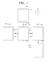
- FIG. 1 is a diagram illustrating an example of determining the orientations of table-top devices that are located in vicinity thereof.
- FIG. 1 illustrates a plurality of table-top devices 100, 100-1, 100-2, 100-3, and 100-4.
- the table-top devices 100, 100-1, 100-2, 100-3, and 100-4 may be connected so as to be able to communicate with one another via a network, wherein the network may be a wired or wireless network. Therefore, the table-top devices 100, 100-1, 100-2, 100-3, and 100-4 may transmit data to or receive data from one another.
- the table-top device 100 may be “directly” connected to the first, second, and third table-top devices 100-1, 100-2, and 100-3, but may not be “directly” connected to the fourth table-top device 100-4.
- the table-top device 100 may be connected "indirectly” to the fourth table-top device 100-4 via the third table-top device 100-3.
- Each of the table-top devices 100, 100-1, 100-2, 100-3 and 100-4 may include a touch screen provided at the top thereof and one or more infrared (IR) transceivers provided on the sides thereof. More specifically, the table-top device 100 includes a touch screen 110 and IR transceivers 150-1 to 150-4; the first table-top device 100-1 includes a touch screen 110-1 and an IR transceiver 150-13; the second table-top device 100-2 includes a touch screen 110-2 and an IR transceiver 150-24; the third table-top device 100-3 includes a touch screen 110-3 and IR transceivers 150-31 and 150-34; and the fourth table-top device 100-4 includes a touch screen 110-4 and an IR transceiver 150-42.
- IR infrared
- the IR transceivers 150-1 to 150-4, 150-13, 150-24, 150-31, 150-34 and 150-42 may be used for IR communications between the table-top devices 100, 100-1, 100-2, 100-3 and 100-4. More specifically, the IR transceivers of a pair of table-top devices that face each other may IR-communicate with each other.
- the IR transceiver 150-1 which is disposed on the west side of the table-top device 100, may IR-communicate with the IR transceiver 150-13, which is disposed on the east side of the first table-top device 100-1.
- the table-top devices 100, 100-1, 100-2, 100-3 and 100-4 may exchange their IDs with one another. More specifically, the IR transceiver 150-1 may transmit the ID of the table-top device 100, i.e., ID_#0, to the IR transceiver 150-13, and the IR transceiver 150-13 may transmit the ID of the first table-top device 100-1, i.e., ID_#1, to the IR transceiver 150-1.
- the exchange of IDs through IR communications may also be performed between the IR transceiver 150-2 and the IR transceiver 150-24, between the IR transceiver 150-3 and the IR transceiver 150-31, and between the IR transceiver 150-34 and the IR transceiver 150-42.
- the table-top device 100 may determine that the first table-top device 100-1 is located on its west side based on ID_#1, which is received from the IR transceiver 150-13 via the IR transceiver 150-1; may determine that the second table-top device 100-2 is located on its north side based on ID_#2, which is received from the IR transceiver 150-24 via the IR transceiver 150-1; and may determine that the third table-top device 100-3 is located on its east side based on ID_#3, which is received from the IR transceiver 150-31 via the IR transceiver 150-1.
- the first table-top device 100-1 may determine that the table-top device 100 is located on its east side based on ID_#0, which is received from the IR transceiver 150-1 via the IR transceiver 150-13
- the second table-top device 100-2 may determine that the table-top device 100 is located on its south side based on ID_#0, which is received from the IR transceiver 150-2 via the IR transceiver 150-24.
- the third table-top device 100-3 may determine that the table-top device 100 is located on its west side based on ID_#0, which is received from the IR transceiver 150-3 via the IR transceiver 150-31; and may determine that the fourth table-top device 100-4 is located on its south side based on ID_#4, which is received from the IR transceiver 150-42 via the IR transceiver 150-34.
- the table-top devices 100, 100-1, 100-2, 100-3, and 100-4 may locate and identify their respective neighboring table-top devices.
- the table-top devices 100, 100-1, 100-2, 100-3, and 100-4 may share their neighboring table-top device location information with one another. Accordingly, the table-top devices 100, 100-1, 100-2, 100-3, and 100-4 may identify not only their direct neighboring table-top devices but also their indirect neighboring table-top devices.
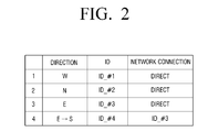
- the table-top devices 100, 100-1, 100-2, 100-3, and 100-4 may generate and maintain a connection/arrangement list regarding all the table-top devices that constitute a network.
- An example of a connection/arrangement list that may be held by the table-top device 100 is illustrated in FIG. 2 .
- entry 1 shows that the first table-top device 100-1, which is directly connected to the table-top device 100 via a network and corresponds to ID_#1, is located on the west side of the table-top device 100;
- entry 2 shows that the second table-top device 100-2, which is directly connected to the table-top device 100 via a network and corresponds to ID_#2, is located on the north side of the table-top device 100;
- entry 3 shows that the third table-top device 100-3, which is directly connected to the table-top device 100 via a network and corresponds to ID_#3, is located on the east side of the table-top device 100.
- Entry 4 shows that the fourth table-top device 100-4, which is indirectly connected to the table-top device 100 via the third table-top device 100-3 and corresponds to ID_#4, is located on the south side of the table-top device 100.
- connection/arrangement list illustrated in FIG. 2 may be used to automatically generate a connection/arrangement map, which will be described in detail.
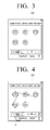
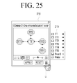
- FIGS. 3 to 5 are diagrams illustrating examples of generating a connection/arrangement map using a connection/arrangement map window and providing the generated connection/arrangement map to a user.
- a connection/arrangement map window 210 may be provided.
- a plurality of table-top devices TT, TT1, TT2, TT3, and TT4 may be displayed in the connection/arrangement map window 210 as icons.
- Each of the icons may be encircled by four outlines that represent the four sides of a corresponding table-top device.
- the table-top device TT may correspond to the table-top device in which the connection/arrangement map program is executed, and the table-top devices TT1, TT2, TT3, and TT4 may correspond to the table-top devices 100, 100-1, 100-2, 100-3, and 100-4, respectively, that are listed in the connection/arrangement list of FIG. 2 .
- connection lines that connect the table-top devices TT, TT1, TT2, TT3, and TT4 may appear.
- connection lines may be drawn from one of the four outlines of a table-top device to one of the four outlines of another table-top device with reference to the connection/arrangement list of FIG. 2 .
- the first table-top device TT1 is located on the west side of the table-top device TT, i.e., the table top device TT is located on the east side of the first table-top device TT-1. Accordingly, the east side of the table-top device TT and the west side of the first table-top device TT1 may face each other.
- connection line may be drawn between the left outline of the table-top device TT and the right outline of the first table-top device TT1.
- connection line may be drawn between the upper outline of the table-top device TT and the lower outline of the second table-top device TT2, and a connection line may be drawn between the right outline of the table-top device TT and the left outline of the third table-top device TT3.
- the fourth table-top device TT4 which corresponds to ID_#4, is located on the south side of the third table-top device TT3, which is located on the east side of the table-top device TT, i.e., the third table-top device TT3 is located on the north side of the third table-top device TT3. Accordingly, a connection line may be drawn between the lower outline of the third table-top device TT3 and the upper outline of the fourth table-top device TT4.
- connection lines drawn between the table-top device TT and the first table-top device TT1, between the table-top device TT and the second table-top device TT2, and between the table-top device TT and the third table-top device TT3 may be solid lines.
- a solid line drawn between two table-top devices may indicate that the two table-top devices are directly connected.
- connection line drawn between the third table-top device TT3 and the fourth table-top device TT4 may be a dotted line, which indicates that the third table-top device TT3 and the fourth table-top device TT4 are connected, but not directly, via the third table-top device TT3.
- a table-top device that is connected to the table-top device TT by a dotted line may be connected to the table-top device, but not directly.
- Two table-top devices that are connected by a solid line may be manually connected to or disconnected from each other, whereas two table-top devices that are connected by a dotted line may not be able to be manually connected to or disconnected from each other.
- the table-top devices TT, TT1, TT2, TT3, and TT4 may be automatically rearranged in the connection/arrangement map window 210.
- An automatic rearrangement of the table-top devices TT, TT1, TT2, TT3, and TT4 may be performed such that the lengths of the connection lines drawn between the table-top devices TT, TT1, TT2, TT3, and TT4 may be minimized.
- a table-top device to which most connection lines are connected may be arranged in the middle;
- the first table-top device TT1 may be arranged on the west side of the table-top device TT to minimize the connection line drawn between the table-top device TT and the first table-top device TT1;
- the second table-top device TT2 may be arranged on the north side of the table-top device TT to minimize the connection line drawn between the table-top device TT and the second table-top device TT2;
- the third table-top device TT3 may be arranged on the east side of the table-top device TT to minimize the connection line drawn between the table-top device TT and the third table-top device TT3;
- the fourth table-top device TT4 may be arranged on
- connection/arrangement map that displays the connections between and the arrangement of the table-top devices TT, TT1, TT2, TT3, and TT4 may be provided in the connection/arrangement map window 210.
- connection/arrangement map window 210 for performing an automatic connection resetting function in response to a 'REPEAT' icon, which is provided in the connection/arrangement map window 210 for performing an automatic connection resetting function, being pressed by the user U, the operations described above in sections '1. Establishment of Information for Generating Connection/Arrangement Map' and '2. Provision of Connection/Arrangement MAP' may be performed again.
- the automatic connection resetting function any updates in the connections between and the arrangement of the table-top devices 100, 100-1, 100-2, 100-3, and 100-4 may be provided. Accordingly, the automatic connection resetting function may be performed when there is a need to update an existing connection/ arrangement map.
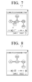
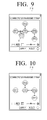
- FIGS. 7 to 10 are diagrams illustrating manually disconnecting table-top devices.
- a 'disconnect' icon ( ⁇ ) may be displayed at a location touched by the user U.
- connection line between the table-top device TT and the first table-top device TT1 may disappear, and the network connection between the table-top device TT and the first table-top device TT1 may be disconnected.
- no 'disconnect' icon ( ⁇ ) may be displayed on the corresponding connection line.
- connection/arrangement map 210 since the connection/arrangement map 210 is being executed by the table-top device TT, but not by the third or fourth table-top device TT3 or TT4, connection settings regarding other table-top devices than the table-top device TT may be prevented from being arbitrarily modified. Accordingly, the network connection between the third table-top device TT3 and the fourth table-top device TT4 cannot be disconnected by using the connection/ arrangement map window 210.
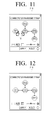
- FIGS. 11 and 12 are diagrams illustrating manually establishing a connection between table-top devices.
- a connection line may appear between the right outline of the first table-top device TT1 and the left outline of the table-top device TT, and a network connection may be established between the first table-top device TT1 and the table-top device TT.
- the table-top device TT1 in response to both the upper outline of the first table-top device TT1 and the lower outline of the table-top device TT being touched at the same time by the user U, the table-top device TT1 may be moved below the table-top device TT, a solid line that connects the upper outline of the first table-top device TT1 and the lower outline of the table-top device TT may be displayed as a connection line, and a network connection may be established between the table-top device and the first table-top device TT1.
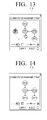
- FIGS. 13 and 14 may be performed in a case in which the first table-top device TT1 is actually moved to the south of the table-top device TT and its movement is recognized by the user U. In this manner, it is possible to avoid any complexity in a connection resetting process.
- connection between the third table-top device TT3 and the fourth table-top device TT4 which is represented by a dotted line, cannot be manually disconnected by the user U.
- no connection may be manually established between the third table-top device TT3 and the fourth table-top device TT4 by the user U.
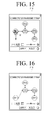
- the user U may manually rearrange the table-top devices TT, TT1, TT2, TT3, and TT4 in the connection/arrangement map window 210.
- the first table-top device TT1 in response to the user U dragging the first table-top device TT1 and dropping it off at a predetermined position, the first table-top device TT1 may be moved to the predetermined position.
- FIGS. 15 and 16 may be performed for precisely reflecting the actual arrangement of the table-top devices TT, TT1, TT2, TT3, and TT4 or for other user convenience-related purposes.
- the example illustrated in FIGS. 15 and 16 may be performed to move a table-top device that is less relevant than other table-top devices to a side or corner of the connection/arrangement map window 210.
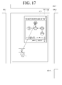
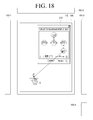
- FIGS. 17 and 18 are diagrams illustrating transmitting content using a connection/ arrangement map.
- the table-top device TT may transmit the content C to the second table-top device TT2.
- the table-top device TT may transmit the content C to the fourth table-top device TT4 via the third table-top device TT3.
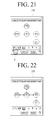
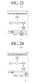
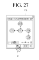
- FIGS. 19 to 22 are diagrams illustrating displaying and deleting connection lines.
- connection lines in the connection/arrangement map window 210 may all disappear.
- connection lines may appear back in the connection/ arrangement map window 210, as shown in FIG. 22 .
- the user U may enlarge or reduce the connection/ arrangement map window 210 to a desired size by dragging a zoom setting tool in the connection/arrangement map window 210.
- the user U may automatically adjust the size of the connection/arrangement map window 210 by touching on an automatic adjustment icon in the connection/arrangement map window 210.
- the user U may withdraw a connected device list 215 by touching on a list icon ( ) in the connection/arrangement map window 210.
- the connected device list 215 includes a plurality of devices that are connected to a network. Referring to the connected device list 215, the devices that are currently being displayed on a connection/arrangement map may be marked with " ⁇ ,” and the devices that are currently not being displayed on the connection/arrangement map may be marked with "o.” Accordingly, the devices that are currently being displayed on a connection/arrangement map may be easily distinguished from the devices that are currently not being displayed on the connection/ arrangement map.
- FIG. 26 is a diagram illustrating an example of printing content using the connected device list 215, which is provided along with a connection/ arrangement map.
- the table-top device TT may transmit the content to the printer together with a 'print' command.
- the printer may print the content C.
- connection/arrangement map currently being displayed in the connection/arrangement map window 210 as a file by touching on an 'APPLY' icon in the connection/arrangement map window 210.
- the stored connection/arrangement map may be transmitted to other devices.
- connection/arrangement map showing the connections between and the arrangement of table-top devices is provided.
- a connection/arrangement map may be provided for various types of devices, other than table-top devices, such as mobile devices, for example, a mobile phone, an MP3 player, a digital camera, a mobile PC, and the like, and non-mobile devices, for example, an electronic frame, an IP TV, a desktop PC, and the like.
- the present invention may be applied not only to a group of homogeneous devices that configure a network but also a group of heterogeneous devices that configure a network.
- the present invention may be applied to a network that is configured by table-top devices and stand-type displays such as a smart board, a printer, and the like.
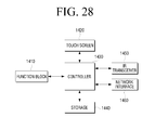
- FIG. 28 is a block diagram of a device to which the present invention can be applied.
- the device includes a function block 1410, a touch screen 1420, a controller 1430, a storage 1440, an IR transceiver 1450, and a network interface 1460.
- the function block 1410 may perform the inherent functions of the device. For example, in a case in which the device is a table-top device, the function block 1410 may perform one or more digital conference-related functions. In another example, in a case in which the device is a mobile phone, the function block 1410 may perform the functions of a mobile phone.
- the touch screen 1420 may perform the functions of a display such as, for example, displaying a connection/arrangement map window 210 and content C, and the functions of a user interface, such as, for example, receiving a user command (for example, a touch, a drag, a drag-and-drop, and the like) in accordance with the results of a function performed by the function block 1410.
- a display such as, for example, displaying a connection/arrangement map window 210 and content C
- a user interface such as, for example, receiving a user command (for example, a touch, a drag, a drag-and-drop, and the like) in accordance with the results of a function performed by the function block 1410.
- the storage 1440 may be a storage medium in which a connection/arrangement map program, a connection/arrangement list, and content may be stored.
- the IR transceiver 1450 may perform IR communication, and the network interface 1460 may perform network communication.
- the controller 1430 may perform a method illustrated in FIG. 29 , thereby providing a multifunctional connection/arrangement map to a user.
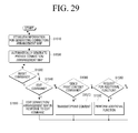
- FIG. 29 is a flowchart illustrating a method of providing a multifunctional connection/ arrangement map to a user, according to an embodiment of the present invention.
- the controller 1430 may establish information for generating a connection/ arrangement map (S1510), may automatically generate a connection/arrangement map, and may provide the generated connection/arrangement map to a user (S1520).
- the method In response to a 'reset' command being received from the user (S1530-Y), the method returns to operation S1510 so that the controller 1430 may perform S1510 and S1520 again.
- the controller 1430 may edit the generated connection/arrangement map in accordance with the 'edit connection/arrangement map' command (S1550).
- the editing of the generated connection/arrangement map may include manually disconnecting the connections between devices shown in the generated connection/arrangement map, manually establishing connections between the devices, and manually rearranging the devices.
- the controller 1430 may transmit or print content (S1570).
- the controller 1430 may perform the requested additional function (S1590).
- the requested additional function may include displaying/deleting connection lines, enlarging/reducing the generated connection/arrangement map, providing a connected device list, and storing the generated connection/arrangement map.
- the IR transceivers 150-1 to 150-4, 150-13, 150-24, 150-31, 150-34, and 150-42 are used to locate the table-top devices 100, 100-1, 100-2, 100-3, and 100-4.
- IR communication is a type of directional communication
- the IR transceivers 150-1 to 150-4, 150-13, 150-24, 150-31, 150-34, and 150-42 may be replaced by other communication devices with directivity.
- the IR transceivers 150-1 to 150-4, 150-13, 150-24, 150-31, 150-34, and 150-42 may be replaced by speaker-and-microphone devices with directivity, ultrasonic transceivers with directivity, or RF transceivers with directivity that can transmit/receive IDs to/from one another when facing one another.
- a table-top device In a case in which a table-top device is faced by another table-top device with a highest received signal strength level, it may locate its neighboring table-top device with a communication device with weak directivity or even without directivity.
- the exchange of IDs between table-top devices may be performed through network communication.
- the IR transceivers of the table-top devices may sequentially issue an ID request to their respective neighboring table-top devices.
- the IR transceivers of the table-top devices may transmit their IDs via a network.
- the IR transceiver 150-1 of the table-top device 100 issues an ID request through IR communication
- the IR transceiver 150-13 of the first table-top device 100-1 may transmit ID_#1 to a network.
- the table-top device 100 may identify that the table-top device on the opposite side thereof, i.e., the table-top device located on the west side thereof, is a table-top device with ID_#1, i.e., the first table-top device 100-1.
- table-top devices may exchange their signal-to-noise ratio (S/N) information or network addresses with one another.
- S/N signal-to-noise ratio
Landscapes
- Engineering & Computer Science (AREA)
- Theoretical Computer Science (AREA)
- General Engineering & Computer Science (AREA)
- Human Computer Interaction (AREA)
- Physics & Mathematics (AREA)
- General Physics & Mathematics (AREA)
- Software Systems (AREA)
- User Interface Of Digital Computer (AREA)
- Information Transfer Between Computers (AREA)
- Digital Computer Display Output (AREA)
Applications Claiming Priority (2)
| Application Number | Priority Date | Filing Date | Title |
|---|---|---|---|
| KR1020090050852A KR20100132173A (ko) | 2009-06-09 | 2009-06-09 | 디바이스들의 연결 관계 및 배치 상태가 나타난 gui 제공방법 및 이를 적용한 디바이스 |
| PCT/KR2010/003703 WO2010143886A2 (ko) | 2009-06-09 | 2010-06-09 | 디바이스들의 연결 관계 및 배치 상태가 나타난 gui 제공방법 및 이를 적용한 디바이스 |
Publications (3)
| Publication Number | Publication Date |
|---|---|
| EP2442218A2 true EP2442218A2 (de) | 2012-04-18 |
| EP2442218A4 EP2442218A4 (de) | 2014-09-10 |
| EP2442218B1 EP2442218B1 (de) | 2017-08-30 |
Family
ID=43309367
Family Applications (1)
| Application Number | Title | Priority Date | Filing Date |
|---|---|---|---|
| EP10786369.8A Not-in-force EP2442218B1 (de) | 2009-06-09 | 2010-06-09 | Verfahren zur bereitstellung einer graphischen benutzeroberfläche mit anzeige von verbindungsverhältnissen und geräteanordnungen sowie vorrichtung zur anwendung dieses verfahrens |
Country Status (5)
| Country | Link |
|---|---|
| US (1) | US20120089917A1 (de) |
| EP (1) | EP2442218B1 (de) |
| KR (1) | KR20100132173A (de) |
| CN (1) | CN102460363B (de) |
| WO (1) | WO2010143886A2 (de) |
Families Citing this family (15)
| Publication number | Priority date | Publication date | Assignee | Title |
|---|---|---|---|---|
| CN102999251B (zh) * | 2012-10-31 | 2016-02-10 | 东莞宇龙通信科技有限公司 | 终端和设备连接管理方法 |
| RU2015121702A (ru) * | 2012-11-07 | 2016-12-27 | Лайф Текнолоджиз Корпорейшн | Средства визуализации данных цифровой пцр |
| US20140223330A1 (en) * | 2013-02-01 | 2014-08-07 | Htc Corporation | Portable electronic device and multi-device integration method thereof |
| AU2014302101A1 (en) | 2013-06-28 | 2016-02-04 | Life Technologies Corporation | Methods and systems for visualizing data quality |
| US20150355787A1 (en) * | 2014-06-06 | 2015-12-10 | Yokogawa Electric Corporation | Dynamically executing multi-device commands on a distributed control |
| US20160117076A1 (en) * | 2014-10-22 | 2016-04-28 | Lg Electronics Inc. | Mobile terminal and control method thereof |
| US10429437B2 (en) * | 2015-05-28 | 2019-10-01 | Keysight Technologies, Inc. | Automatically generated test diagram |
| KR102642398B1 (ko) * | 2015-06-22 | 2024-02-29 | 삼성디스플레이 주식회사 | 표시 장치 |
| CN107302703A (zh) * | 2016-04-15 | 2017-10-27 | 中兴通讯股份有限公司 | 音视频播放方法及装置 |
| CN108206754B (zh) * | 2016-12-19 | 2021-03-09 | 北京君正集成电路股份有限公司 | 智能家居的网络拓扑生成方法和装置 |
| CN108206784B (zh) * | 2016-12-19 | 2020-12-29 | 北京君正集成电路股份有限公司 | 智能家居的网络拓扑生成方法和装置 |
| CN108206755B (zh) * | 2016-12-19 | 2021-01-22 | 北京君正集成电路股份有限公司 | 智能家居的网络拓扑生成方法和装置 |
| US20200090386A1 (en) * | 2018-09-19 | 2020-03-19 | International Business Machines Corporation | Interactive relationship visualization control interface |
| CN114153531A (zh) * | 2020-08-18 | 2022-03-08 | 华为技术有限公司 | 管理物联网设备的方法和装置 |
| US11157160B1 (en) * | 2020-11-09 | 2021-10-26 | Dell Products, L.P. | Graphical user interface (GUI) for controlling virtual workspaces produced across information handling systems (IHSs) |
Family Cites Families (20)
| Publication number | Priority date | Publication date | Assignee | Title |
|---|---|---|---|---|
| US5615325A (en) * | 1994-09-29 | 1997-03-25 | Intel Corporation | Graphical viewer for heirarchical datasets |
| US5889954A (en) * | 1996-12-20 | 1999-03-30 | Ericsson Inc. | Network manager providing advanced interconnection capability |
| CN1383532A (zh) * | 2000-06-09 | 2002-12-04 | 精工爱普生株式会社 | 图像指定文件的制作和使用了该文件的图像的播放 |
| JP2003289313A (ja) * | 2002-03-28 | 2003-10-10 | Hewlett Packard Japan Ltd | 仮想ローカル・エリア・ネットワーク(vlan)を設定する方法 |
| US20040155899A1 (en) * | 2003-02-11 | 2004-08-12 | Conrad Jeffrey Richard | Method and system for presenting an arrangement of management devices operable in a managed network |
| US20050015444A1 (en) * | 2003-07-15 | 2005-01-20 | Darwin Rambo | Audio/video conferencing system |
| US7716585B2 (en) * | 2003-08-28 | 2010-05-11 | Microsoft Corporation | Multi-dimensional graphical display of discovered wireless devices |
| US7617457B2 (en) * | 2004-01-07 | 2009-11-10 | At&T Intellectual Property I, L.P. | System and method for collaborative call management |
| US8639819B2 (en) * | 2004-02-05 | 2014-01-28 | Nokia Corporation | Ad-hoc connection between electronic devices |
| KR101013143B1 (ko) * | 2004-06-29 | 2011-02-10 | 삼성전자주식회사 | 모니터 관리시스템 |
| US7266777B2 (en) * | 2004-09-08 | 2007-09-04 | Universal Electronics Inc. | Configurable controlling device having an associated editing program |
| US8407347B2 (en) * | 2004-11-19 | 2013-03-26 | Xiao Qian Zhang | Method of operating multiple input and output devices through a single computer |
| US7814457B2 (en) * | 2005-01-19 | 2010-10-12 | Sap Ag | System and method for revising flow diagrams displaying a process |
| US7587675B2 (en) * | 2006-02-28 | 2009-09-08 | Microsoft Corporation | Network map |
| DE102006047770A1 (de) * | 2006-10-10 | 2008-04-24 | Dräger Medical AG & Co. KG | System zur Steuerung und Überwachung von Therapiemodulen eines medizinischen Arbeitsplatzes |
| US8223363B2 (en) * | 2007-01-30 | 2012-07-17 | Ricoh Company, Ltd. | Universal print driver with best fit discovery |
| US8380246B2 (en) * | 2007-03-01 | 2013-02-19 | Microsoft Corporation | Connecting mobile devices via interactive input medium |
| JP2008234122A (ja) * | 2007-03-19 | 2008-10-02 | Meidensha Corp | 画面表示情報の連携方式、および連携方法 |
| JP2009026255A (ja) * | 2007-07-24 | 2009-02-05 | Hitachi Ltd | データ移行方法、データ移行システム、及びデータ移行プログラム |
| JP5620134B2 (ja) * | 2009-03-30 | 2014-11-05 | アバイア インク. | グラフィカル表示を用いて通信セッションの信頼関係を管理するシステムと方法。 |
-
2009
- 2009-06-09 KR KR1020090050852A patent/KR20100132173A/ko not_active Ceased
-
2010
- 2010-06-09 US US13/377,385 patent/US20120089917A1/en not_active Abandoned
- 2010-06-09 CN CN201080025526.5A patent/CN102460363B/zh not_active Expired - Fee Related
- 2010-06-09 EP EP10786369.8A patent/EP2442218B1/de not_active Not-in-force
- 2010-06-09 WO PCT/KR2010/003703 patent/WO2010143886A2/ko not_active Ceased
Also Published As
| Publication number | Publication date |
|---|---|
| US20120089917A1 (en) | 2012-04-12 |
| CN102460363A (zh) | 2012-05-16 |
| WO2010143886A3 (ko) | 2011-03-31 |
| WO2010143886A2 (ko) | 2010-12-16 |
| CN102460363B (zh) | 2017-07-14 |
| EP2442218B1 (de) | 2017-08-30 |
| EP2442218A4 (de) | 2014-09-10 |
| KR20100132173A (ko) | 2010-12-17 |
Similar Documents
| Publication | Publication Date | Title |
|---|---|---|
| EP2442218A2 (de) | Verfahren zur bereitstellung einer graphischen benutzeroberfläche mit anzeige von verbindungsverhältnissen und geräteanordnungen sowie vorrichtung zur anwendung dieses verfahrens | |
| US11729355B2 (en) | Video conferencing during real time collaboration on a virtual canvas | |
| KR101943987B1 (ko) | 디바이스 간의 페이지 공유 시스템 및 방법 | |
| CN102033697B (zh) | 终端设备、服务器设备、显示控制方法及程序 | |
| JP5174372B2 (ja) | 機能アイコンの表示システム及び方法 | |
| KR101491045B1 (ko) | 컨텐츠 공유 장치 및 방법 | |
| JP6656026B2 (ja) | 情報処理装置、情報処理の制御方法、並びにコンピュータプログラム | |
| KR102304365B1 (ko) | 디스플레이 장치 및 그의 명령 전송 방법 | |
| EP2261793A2 (de) | Verfahren zur Übertragung von Inhalt mit intuitiver Anzeige der Inhaltsübertragungsadresse und Vorrichtung damit | |
| EP2642773A2 (de) | Verfahren und Vorrichtung zur Verwaltung einer Kommunikationsgruppe mit drahtlosem direktem Zugriff | |
| CN102436663A (zh) | 用于对增强现实进行选择性过滤的用户设备、服务器和方法 | |
| KR20100108422A (ko) | 멀티 모니터 컴퓨터 시스템에서 다수의 소스 컴퓨터로부터의 비디오 데이터를 디스플레이하기 위한 방법 및 장치 | |
| KR20150032066A (ko) | 화면 미러링 방법 및 그에 따른 소스 기기 | |
| CN103631485A (zh) | 消息处理方法和支持所述方法的终端 | |
| KR20160053641A (ko) | 멀티 디스플레이 제어 방법 및 그 전자 장치 | |
| JP2007522546A (ja) | マルチスクリーン表示システム | |
| CN104238873B (zh) | 信息处理设备、信息处理方法和程序 | |
| JP2018510395A (ja) | 状態切替方法、装置、プログラム、及び記録媒体 | |
| CN105320433A (zh) | 移动终端的近距离数据传输方法及其移动终端 | |
| KR20150042098A (ko) | 엔에프씨를 이용한 화상형성장치의 초기 설정 방법 및 이를 수행하기 위한 화상형성장치 | |
| JP7298224B2 (ja) | 表示装置、及び表示方法 | |
| EP3439311B1 (de) | Bildübertragungsausrüstung | |
| WO2023045745A1 (zh) | 多屏系统的控制方法、介质及其电子设备 | |
| CN111610920B (zh) | 多设备控制方法、装置和系统 | |
| CN103607620B (zh) | 控制智能电视的移动通信终端方法及装置 |
Legal Events
| Date | Code | Title | Description |
|---|---|---|---|
| PUAI | Public reference made under article 153(3) epc to a published international application that has entered the european phase |
Free format text: ORIGINAL CODE: 0009012 |
|
| 17P | Request for examination filed |
Effective date: 20120109 |
|
| AK | Designated contracting states |
Kind code of ref document: A2 Designated state(s): AL AT BE BG CH CY CZ DE DK EE ES FI FR GB GR HR HU IE IS IT LI LT LU LV MC MK MT NL NO PL PT RO SE SI SK SM TR |
|
| DAX | Request for extension of the european patent (deleted) | ||
| RAP1 | Party data changed (applicant data changed or rights of an application transferred) |
Owner name: SAMSUNG ELECTRONICS CO., LTD. |
|
| A4 | Supplementary search report drawn up and despatched |
Effective date: 20140808 |
|
| RIC1 | Information provided on ipc code assigned before grant |
Ipc: G06F 9/44 20060101ALI20140804BHEP Ipc: G06F 3/0488 20130101ALI20140804BHEP Ipc: G06F 3/0486 20130101ALI20140804BHEP Ipc: G06F 3/048 20130101AFI20140804BHEP Ipc: G06F 3/14 20060101ALI20140804BHEP |
|
| 17Q | First examination report despatched |
Effective date: 20150826 |
|
| GRAP | Despatch of communication of intention to grant a patent |
Free format text: ORIGINAL CODE: EPIDOSNIGR1 |
|
| STAA | Information on the status of an ep patent application or granted ep patent |
Free format text: STATUS: GRANT OF PATENT IS INTENDED |
|
| INTG | Intention to grant announced |
Effective date: 20170310 |
|
| GRAS | Grant fee paid |
Free format text: ORIGINAL CODE: EPIDOSNIGR3 |
|
| GRAA | (expected) grant |
Free format text: ORIGINAL CODE: 0009210 |
|
| STAA | Information on the status of an ep patent application or granted ep patent |
Free format text: STATUS: THE PATENT HAS BEEN GRANTED |
|
| AK | Designated contracting states |
Kind code of ref document: B1 Designated state(s): AL AT BE BG CH CY CZ DE DK EE ES FI FR GB GR HR HU IE IS IT LI LT LU LV MC MK MT NL NO PL PT RO SE SI SK SM TR |
|
| REG | Reference to a national code |
Ref country code: GB Ref legal event code: FG4D |
|
| REG | Reference to a national code |
Ref country code: CH Ref legal event code: EP |
|
| REG | Reference to a national code |
Ref country code: AT Ref legal event code: REF Ref document number: 924185 Country of ref document: AT Kind code of ref document: T Effective date: 20170915 |
|
| REG | Reference to a national code |
Ref country code: IE Ref legal event code: FG4D |
|
| REG | Reference to a national code |
Ref country code: DE Ref legal event code: R096 Ref document number: 602010044864 Country of ref document: DE |
|
| REG | Reference to a national code |
Ref country code: NL Ref legal event code: FP |
|
| REG | Reference to a national code |
Ref country code: LT Ref legal event code: MG4D |
|
| REG | Reference to a national code |
Ref country code: AT Ref legal event code: MK05 Ref document number: 924185 Country of ref document: AT Kind code of ref document: T Effective date: 20170830 |
|
| PG25 | Lapsed in a contracting state [announced via postgrant information from national office to epo] |
Ref country code: FI Free format text: LAPSE BECAUSE OF FAILURE TO SUBMIT A TRANSLATION OF THE DESCRIPTION OR TO PAY THE FEE WITHIN THE PRESCRIBED TIME-LIMIT Effective date: 20170830 Ref country code: AT Free format text: LAPSE BECAUSE OF FAILURE TO SUBMIT A TRANSLATION OF THE DESCRIPTION OR TO PAY THE FEE WITHIN THE PRESCRIBED TIME-LIMIT Effective date: 20170830 Ref country code: SE Free format text: LAPSE BECAUSE OF FAILURE TO SUBMIT A TRANSLATION OF THE DESCRIPTION OR TO PAY THE FEE WITHIN THE PRESCRIBED TIME-LIMIT Effective date: 20170830 Ref country code: HR Free format text: LAPSE BECAUSE OF FAILURE TO SUBMIT A TRANSLATION OF THE DESCRIPTION OR TO PAY THE FEE WITHIN THE PRESCRIBED TIME-LIMIT Effective date: 20170830 Ref country code: LT Free format text: LAPSE BECAUSE OF FAILURE TO SUBMIT A TRANSLATION OF THE DESCRIPTION OR TO PAY THE FEE WITHIN THE PRESCRIBED TIME-LIMIT Effective date: 20170830 Ref country code: NO Free format text: LAPSE BECAUSE OF FAILURE TO SUBMIT A TRANSLATION OF THE DESCRIPTION OR TO PAY THE FEE WITHIN THE PRESCRIBED TIME-LIMIT Effective date: 20171130 |
|
| PG25 | Lapsed in a contracting state [announced via postgrant information from national office to epo] |
Ref country code: GR Free format text: LAPSE BECAUSE OF FAILURE TO SUBMIT A TRANSLATION OF THE DESCRIPTION OR TO PAY THE FEE WITHIN THE PRESCRIBED TIME-LIMIT Effective date: 20171201 Ref country code: BG Free format text: LAPSE BECAUSE OF FAILURE TO SUBMIT A TRANSLATION OF THE DESCRIPTION OR TO PAY THE FEE WITHIN THE PRESCRIBED TIME-LIMIT Effective date: 20171130 Ref country code: ES Free format text: LAPSE BECAUSE OF FAILURE TO SUBMIT A TRANSLATION OF THE DESCRIPTION OR TO PAY THE FEE WITHIN THE PRESCRIBED TIME-LIMIT Effective date: 20170830 Ref country code: LV Free format text: LAPSE BECAUSE OF FAILURE TO SUBMIT A TRANSLATION OF THE DESCRIPTION OR TO PAY THE FEE WITHIN THE PRESCRIBED TIME-LIMIT Effective date: 20170830 Ref country code: IS Free format text: LAPSE BECAUSE OF FAILURE TO SUBMIT A TRANSLATION OF THE DESCRIPTION OR TO PAY THE FEE WITHIN THE PRESCRIBED TIME-LIMIT Effective date: 20171230 |
|
| PG25 | Lapsed in a contracting state [announced via postgrant information from national office to epo] |
Ref country code: RO Free format text: LAPSE BECAUSE OF FAILURE TO SUBMIT A TRANSLATION OF THE DESCRIPTION OR TO PAY THE FEE WITHIN THE PRESCRIBED TIME-LIMIT Effective date: 20170830 Ref country code: PL Free format text: LAPSE BECAUSE OF FAILURE TO SUBMIT A TRANSLATION OF THE DESCRIPTION OR TO PAY THE FEE WITHIN THE PRESCRIBED TIME-LIMIT Effective date: 20170830 Ref country code: CZ Free format text: LAPSE BECAUSE OF FAILURE TO SUBMIT A TRANSLATION OF THE DESCRIPTION OR TO PAY THE FEE WITHIN THE PRESCRIBED TIME-LIMIT Effective date: 20170830 Ref country code: DK Free format text: LAPSE BECAUSE OF FAILURE TO SUBMIT A TRANSLATION OF THE DESCRIPTION OR TO PAY THE FEE WITHIN THE PRESCRIBED TIME-LIMIT Effective date: 20170830 |
|
| PG25 | Lapsed in a contracting state [announced via postgrant information from national office to epo] |
Ref country code: SM Free format text: LAPSE BECAUSE OF FAILURE TO SUBMIT A TRANSLATION OF THE DESCRIPTION OR TO PAY THE FEE WITHIN THE PRESCRIBED TIME-LIMIT Effective date: 20170830 Ref country code: SK Free format text: LAPSE BECAUSE OF FAILURE TO SUBMIT A TRANSLATION OF THE DESCRIPTION OR TO PAY THE FEE WITHIN THE PRESCRIBED TIME-LIMIT Effective date: 20170830 Ref country code: IT Free format text: LAPSE BECAUSE OF FAILURE TO SUBMIT A TRANSLATION OF THE DESCRIPTION OR TO PAY THE FEE WITHIN THE PRESCRIBED TIME-LIMIT Effective date: 20170830 Ref country code: EE Free format text: LAPSE BECAUSE OF FAILURE TO SUBMIT A TRANSLATION OF THE DESCRIPTION OR TO PAY THE FEE WITHIN THE PRESCRIBED TIME-LIMIT Effective date: 20170830 |
|
| REG | Reference to a national code |
Ref country code: DE Ref legal event code: R097 Ref document number: 602010044864 Country of ref document: DE |
|
| PLBE | No opposition filed within time limit |
Free format text: ORIGINAL CODE: 0009261 |
|
| STAA | Information on the status of an ep patent application or granted ep patent |
Free format text: STATUS: NO OPPOSITION FILED WITHIN TIME LIMIT |
|
| PGFP | Annual fee paid to national office [announced via postgrant information from national office to epo] |
Ref country code: DE Payment date: 20180522 Year of fee payment: 9 |
|
| 26N | No opposition filed |
Effective date: 20180531 |
|
| PG25 | Lapsed in a contracting state [announced via postgrant information from national office to epo] |
Ref country code: SI Free format text: LAPSE BECAUSE OF FAILURE TO SUBMIT A TRANSLATION OF THE DESCRIPTION OR TO PAY THE FEE WITHIN THE PRESCRIBED TIME-LIMIT Effective date: 20170830 |
|
| PGFP | Annual fee paid to national office [announced via postgrant information from national office to epo] |
Ref country code: NL Payment date: 20180523 Year of fee payment: 9 |
|
| PGFP | Annual fee paid to national office [announced via postgrant information from national office to epo] |
Ref country code: GB Payment date: 20180523 Year of fee payment: 9 |
|
| REG | Reference to a national code |
Ref country code: CH Ref legal event code: PL |
|
| REG | Reference to a national code |
Ref country code: BE Ref legal event code: MM Effective date: 20180630 |
|
| REG | Reference to a national code |
Ref country code: IE Ref legal event code: MM4A |
|
| PG25 | Lapsed in a contracting state [announced via postgrant information from national office to epo] |
Ref country code: MC Free format text: LAPSE BECAUSE OF FAILURE TO SUBMIT A TRANSLATION OF THE DESCRIPTION OR TO PAY THE FEE WITHIN THE PRESCRIBED TIME-LIMIT Effective date: 20170830 Ref country code: LU Free format text: LAPSE BECAUSE OF NON-PAYMENT OF DUE FEES Effective date: 20180609 |
|
| PG25 | Lapsed in a contracting state [announced via postgrant information from national office to epo] |
Ref country code: IE Free format text: LAPSE BECAUSE OF NON-PAYMENT OF DUE FEES Effective date: 20180609 Ref country code: FR Free format text: LAPSE BECAUSE OF NON-PAYMENT OF DUE FEES Effective date: 20180630 Ref country code: CH Free format text: LAPSE BECAUSE OF NON-PAYMENT OF DUE FEES Effective date: 20180630 Ref country code: LI Free format text: LAPSE BECAUSE OF NON-PAYMENT OF DUE FEES Effective date: 20180630 |
|
| PG25 | Lapsed in a contracting state [announced via postgrant information from national office to epo] |
Ref country code: BE Free format text: LAPSE BECAUSE OF NON-PAYMENT OF DUE FEES Effective date: 20180630 |
|
| REG | Reference to a national code |
Ref country code: DE Ref legal event code: R119 Ref document number: 602010044864 Country of ref document: DE |
|
| PG25 | Lapsed in a contracting state [announced via postgrant information from national office to epo] |
Ref country code: MT Free format text: LAPSE BECAUSE OF NON-PAYMENT OF DUE FEES Effective date: 20180609 |
|
| REG | Reference to a national code |
Ref country code: NL Ref legal event code: MM Effective date: 20190701 |
|
| GBPC | Gb: european patent ceased through non-payment of renewal fee |
Effective date: 20190609 |
|
| PG25 | Lapsed in a contracting state [announced via postgrant information from national office to epo] |
Ref country code: TR Free format text: LAPSE BECAUSE OF FAILURE TO SUBMIT A TRANSLATION OF THE DESCRIPTION OR TO PAY THE FEE WITHIN THE PRESCRIBED TIME-LIMIT Effective date: 20170830 |
|
| PG25 | Lapsed in a contracting state [announced via postgrant information from national office to epo] |
Ref country code: GB Free format text: LAPSE BECAUSE OF NON-PAYMENT OF DUE FEES Effective date: 20190609 Ref country code: DE Free format text: LAPSE BECAUSE OF NON-PAYMENT OF DUE FEES Effective date: 20200101 Ref country code: NL Free format text: LAPSE BECAUSE OF NON-PAYMENT OF DUE FEES Effective date: 20190701 |
|
| PG25 | Lapsed in a contracting state [announced via postgrant information from national office to epo] |
Ref country code: PT Free format text: LAPSE BECAUSE OF FAILURE TO SUBMIT A TRANSLATION OF THE DESCRIPTION OR TO PAY THE FEE WITHIN THE PRESCRIBED TIME-LIMIT Effective date: 20170830 Ref country code: HU Free format text: LAPSE BECAUSE OF FAILURE TO SUBMIT A TRANSLATION OF THE DESCRIPTION OR TO PAY THE FEE WITHIN THE PRESCRIBED TIME-LIMIT; INVALID AB INITIO Effective date: 20100609 |
|
| PG25 | Lapsed in a contracting state [announced via postgrant information from national office to epo] |
Ref country code: CY Free format text: LAPSE BECAUSE OF FAILURE TO SUBMIT A TRANSLATION OF THE DESCRIPTION OR TO PAY THE FEE WITHIN THE PRESCRIBED TIME-LIMIT Effective date: 20170830 Ref country code: MK Free format text: LAPSE BECAUSE OF NON-PAYMENT OF DUE FEES Effective date: 20170830 |
|
| PG25 | Lapsed in a contracting state [announced via postgrant information from national office to epo] |
Ref country code: AL Free format text: LAPSE BECAUSE OF FAILURE TO SUBMIT A TRANSLATION OF THE DESCRIPTION OR TO PAY THE FEE WITHIN THE PRESCRIBED TIME-LIMIT Effective date: 20170830 |