EP2442025A1 - Vapor cooker - Google Patents
Vapor cooker Download PDFInfo
- Publication number
- EP2442025A1 EP2442025A1 EP10786209A EP10786209A EP2442025A1 EP 2442025 A1 EP2442025 A1 EP 2442025A1 EP 10786209 A EP10786209 A EP 10786209A EP 10786209 A EP10786209 A EP 10786209A EP 2442025 A1 EP2442025 A1 EP 2442025A1
- Authority
- EP
- European Patent Office
- Prior art keywords
- water
- water tank
- steam
- hardness
- steam generating
- Prior art date
- Legal status (The legal status is an assumption and is not a legal conclusion. Google has not performed a legal analysis and makes no representation as to the accuracy of the status listed.)
- Withdrawn
Links
- XLYOFNOQVPJJNP-UHFFFAOYSA-N water Substances O XLYOFNOQVPJJNP-UHFFFAOYSA-N 0.000 claims abstract description 183
- 238000010438 heat treatment Methods 0.000 claims abstract description 45
- 238000004140 cleaning Methods 0.000 claims abstract description 32
- 238000001514 detection method Methods 0.000 claims abstract description 19
- 238000010411 cooking Methods 0.000 description 26
- KRKNYBCHXYNGOX-UHFFFAOYSA-N citric acid Chemical compound OC(=O)CC(O)(C(O)=O)CC(O)=O KRKNYBCHXYNGOX-UHFFFAOYSA-N 0.000 description 6
- 238000001816 cooling Methods 0.000 description 6
- 238000000034 method Methods 0.000 description 6
- 239000008399 tap water Substances 0.000 description 4
- 235000020679 tap water Nutrition 0.000 description 4
- 230000003247 decreasing effect Effects 0.000 description 2
- 238000010586 diagram Methods 0.000 description 2
- 229920006395 saturated elastomer Polymers 0.000 description 2
- 238000000926 separation method Methods 0.000 description 2
- VTYYLEPIZMXCLO-UHFFFAOYSA-L Calcium carbonate Chemical compound [Ca+2].[O-]C([O-])=O VTYYLEPIZMXCLO-UHFFFAOYSA-L 0.000 description 1
- 238000004891 communication Methods 0.000 description 1
- 239000008233 hard water Substances 0.000 description 1
- 238000007654 immersion Methods 0.000 description 1
- 239000012535 impurity Substances 0.000 description 1
- 229910052500 inorganic mineral Inorganic materials 0.000 description 1
- 239000012212 insulator Substances 0.000 description 1
- 239000004973 liquid crystal related substance Substances 0.000 description 1
- 238000005259 measurement Methods 0.000 description 1
- 239000011707 mineral Substances 0.000 description 1
- 239000008234 soft water Substances 0.000 description 1
Images

Classifications
-
- F—MECHANICAL ENGINEERING; LIGHTING; HEATING; WEAPONS; BLASTING
- F24—HEATING; RANGES; VENTILATING
- F24C—DOMESTIC STOVES OR RANGES ; DETAILS OF DOMESTIC STOVES OR RANGES, OF GENERAL APPLICATION
- F24C15/00—Details
- F24C15/32—Arrangements of ducts for hot gases, e.g. in or around baking ovens
- F24C15/322—Arrangements of ducts for hot gases, e.g. in or around baking ovens with forced circulation
- F24C15/327—Arrangements of ducts for hot gases, e.g. in or around baking ovens with forced circulation with air moisturising
-
- F—MECHANICAL ENGINEERING; LIGHTING; HEATING; WEAPONS; BLASTING
- F22—STEAM GENERATION
- F22B—METHODS OF STEAM GENERATION; STEAM BOILERS
- F22B1/00—Methods of steam generation characterised by form of heating method
- F22B1/28—Methods of steam generation characterised by form of heating method in boilers heated electrically
- F22B1/284—Methods of steam generation characterised by form of heating method in boilers heated electrically with water in reservoirs
-
- F—MECHANICAL ENGINEERING; LIGHTING; HEATING; WEAPONS; BLASTING
- F22—STEAM GENERATION
- F22B—METHODS OF STEAM GENERATION; STEAM BOILERS
- F22B37/00—Component parts or details of steam boilers
- F22B37/02—Component parts or details of steam boilers applicable to more than one kind or type of steam boiler
- F22B37/56—Boiler cleaning control devices, e.g. for ascertaining proper duration of boiler blow-down
-
- G—PHYSICS
- G01—MEASURING; TESTING
- G01F—MEASURING VOLUME, VOLUME FLOW, MASS FLOW OR LIQUID LEVEL; METERING BY VOLUME
- G01F23/00—Indicating or measuring liquid level or level of fluent solid material, e.g. indicating in terms of volume or indicating by means of an alarm
- G01F23/22—Indicating or measuring liquid level or level of fluent solid material, e.g. indicating in terms of volume or indicating by means of an alarm by measuring physical variables, other than linear dimensions, pressure or weight, dependent on the level to be measured, e.g. by difference of heat transfer of steam or water
- G01F23/24—Indicating or measuring liquid level or level of fluent solid material, e.g. indicating in terms of volume or indicating by means of an alarm by measuring physical variables, other than linear dimensions, pressure or weight, dependent on the level to be measured, e.g. by difference of heat transfer of steam or water by measuring variations of resistance of resistors due to contact with conductor fluid
- G01F23/241—Indicating or measuring liquid level or level of fluent solid material, e.g. indicating in terms of volume or indicating by means of an alarm by measuring physical variables, other than linear dimensions, pressure or weight, dependent on the level to be measured, e.g. by difference of heat transfer of steam or water by measuring variations of resistance of resistors due to contact with conductor fluid for discrete levels
- G01F23/243—Schematic arrangements of probes combined with measuring circuits
Definitions
- the present invention relates to a steam cooker that cooks, with steam, an item to be cooked.
- a conventional steam cooker is disclosed in patent document 1.
- This steam cooker includes a steam generating device for supplying steam to a heating chamber that stores an item to be cooked.
- a steam generating heater is provided within a housing to which water is supplied from a removable water tank.
- the housing is provided with a water level sensor that is formed with a self-heating heat-sensing element.
- the water is supplied from the water tank into the housing of the steam generating device.
- the water supply is stopped, and the water heated by the steam generating heater is esteamated to generate steam.
- the steam generated by the steam generating device is supplied to the heating chamber, and the item to be cooked within the heating chamber is cooked with the steam.
- the water supplied to the steam generating device contains impurities; the water is esteamated by heating with the steam generating heater, and scale is attached to the housing and the water level sensor. Hence, when the water level within the housing becomes lower than a predetermined water level, the water level sensor is stopped. Thus, it is possible to reduce the attachment of scale to the water level sensor and prevent the water level sensor from performing erroneous detection.
- the thermal conductivity thereof is reduced, the amount of steam generated is reduced and the performance of the steam generating device is reduced. Since tap water in Japan is mainly soft water, the amount of scale attached is low, and the performance is only slightly reduced in the useful life of the steam cooker (for example, 10 years).
- Patent document 1 JP-A-2005-337627 (Pages 6-14 and Fig. 1 )
- An object of the present invention is to provide a steam cooker that can enhance convenience.
- a steam cooker including: a heating chamber that stores an item to be cooked; a removable water tank; a steam generating device that includes a housing to which water is supplied from the water tank and that heats, with a steam generating heater, the water within the housing and supplies steam to the heating chamber; a hardness detection portion that includes a plurality of electrodes which are immersed in water within the water tank or a water storage portion coupled to the water tank and that detects a hardness of the water within the water tank by a resistance between the electrodes; and a notification portion that provides a notification of a cleaning time of the steam generating device, in which, when the hardness of the water within the water tank that is detected by the hardness detection portion is high, an interval of cleaning of the steam generating device is shorter than an interval set when the hardness detected by the hardness detection portion is low.
- the water tank storing tap water or the like is fitted, and the electrodes of the hardness detection portion are immersed in the water within the water tank or the water storage portion coupled to the water tank.
- the hardness of the water within the water tank is detected by the resistance between the plurality of electrodes.
- the drive time of the steam generating device reaches the cleaning time determined according to the hardness of the water within the water tank, a notification of the cleaning time is provided to a user by display, sound or the like with the notification portion.
- the interval of the cleaning of the steam generating device is set shorter than an interval set when the hardness detected by the hardness detection portion is low.
- the water level of the water tank is detected by continuity between the electrodes.
- the electrodes that are immersed in the water within the water tank or the water storage portion are electrically discontinuous, the amount of water in the water tank is determined to be insufficient, and, for example, the steam cooker is placed on standby for starting the cooking.
- the cleaning time of the steam generating device is determined to arrive.
- a hardness detection portion includes a plurality of electrodes which are immersed in water within a water tank or a water storage portion coupled to the water tank and detects the hardness of the water within the water tank by a resistance between the electrodes, and, when the hardness of the water within the water tank is high, the interval of cleaning of the steam generating device is set shorter than an interval set when the hardness is low, and a notification of a cleaning time is provided by a notification portion, it is possible to clean the steam generating device according to the hardness of the water within the water tank without complicated operations being performed by a user. It is therefore possible to enhance the convenience of the steam cooker.
- Fig. 1 is a front cross-sectional view showing a steam cooker according to an embodiment of the present invention.
- the steam cooker 1 includes, within a body enclosure portion 10, a heating chamber 20 that stores an item to be cooked 90.
- the heating chamber 20 is box-shaped whose front surface is open and is opened and closed by a door (unillustrated).
- a heat insulator 14 is provided on the perimeter surface of the heating chamber 20, and a temperature sensor 76 is provided on the ceiling surface within the heating chamber 20.
- protrusion portions 23 and 25 are vertically provided; on the right side wall, protrusion portions 24 and 26 are provided at the same height as the protrusion portions 23 and 25, respectively. Between the protrusion portions 23 and 24 or between the protrusion portions 25 and 26, a tray 21 having a placement net 22 on which the item to be cooked 90 is placed is put.
- a circulation duct 27 is provided behind the heating chamber 20.
- the circulation duct 27 there are provided an inlet 20a that is open at the middle portion of the back surface of the heating chamber 20 and outlets 20b, 20c, 20d, 20e, 20f and 20g that are open in the perimeter portion of the back surface.
- a circulation fan 28 see Fig. 3
- a heater 29 see Fig. 3 . The circulation fan 28 and the heater 29 are driven, and thus steam and air within the heating chamber 20 flow into the circulation duct 27 through the inlet 20a, and they are heated and are discharged through the outlets 20b to 20g.
- an outside air inflow duct 56 that includes a cooling fan 53, a waveguide 60 and a magnetron 50.
- an outside air inflow port 62 is open in the lower surface of the body enclosure 10, and the cooling fan 53 is arranged to face the outside air inflow port 62.
- the magnetron 50 supplies microwaves into the heating chamber 20 through the waveguide 60.
- an antenna 51 that is rotated by an antenna motor 52 is provided, and the microwaves supplied to the heating chamber 20 are made uniform.
- an intake port 57 and an exhaust port 58 In the right side wall of the heating chamber 20, there are provided an intake port 57 and an exhaust port 58. In a position within the outside air inflow duct 56 that faces the intake port 57, an intake fan 55 is provided. The outside air inflow duct 56 is separated by a separation plate 34 from the right upper portion of the heating chamber 20.
- the exhaust port 58 communicates with an exhaust duct 72 whose open portion 73 is open to the upper surface of the body enclosure 10.
- the exhaust duct 72 is provided with a humidity sensor 75 and a temperature sensor 74.
- a removable water tank 30 is provided above the separation plate 34 on the right side of the heating chamber 20, a removable water tank 30 is provided.
- a water storage portion 31 is provided next to the water tank 30.
- the water storage portion 31 is coupled to the water tank 30 through a communication passage 32 via a water stop valve (unillustrated) provided on the side of the back surface of the water tank 30; when the water tank 30 is fitted, the water within the water tank 30 flows in.
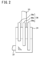
- Fig. 2 shows a front cross-sectional view of the water storage portion 31.
- a water level sensor 36 that is immersed in the water passed from the water tank 30 and that detects the water level.
- the water level sensor 36 has electrodes 36a, 36b and 36c in descending order of depth of immersion; the water level of the water tank 30 is detected by continuity between the electrodes 36a, 36b and 36c.
- a notification of lack of water is provided by a display portion 4 (see Fig. 3 ) or the like; when the notification is provided before the start of cooking, the steam cooker 1 is placed on standby for starting the cooking.
- the electrodes 36a and 36b become electrically discontinuous, for example, the cooking is temporarily stopped.
- a resistance between the electrodes 36a and 36b of the water level sensor 36 or between the electrodes 36a and 36c is detected, and thus the hardness of water in the water tank 30 is detected.
- the hardness of water is indicated by the content of CaCo 3 ; the unit thereof is ppm, mg/L or dH. Since, as the hardness of water becomes higher, its electrical conductivity is increased, its resistance is decreased.
- the water level sensor 36 is configured to include a hardness detection portion that detects the hardness of water in the water tank 30.
- the water level sensor 36 may be provided on the upper surface of the water tank 30, and a terminal portion that makes contact with the electrodes 36a, 36b and 36c when the water tank 30 is fitted may be provided in the body enclosure 10.
- a steam generating device 40 is provided in an upper portion of the right side wall of the heating chamber 2.
- a steam generating heater 42 is provided within a metallic housing 41.
- a water supply pipe 33 that is extended from the water storage portion 31 is connected to the housing 41; a discharge port 44 that faces the heating chamber 2 is open.
- a water supply pump 35 that is provided in the path of the water supply pipe 33 is driven, and thus the water is supplied from the water storage portion 31 into the housing 41.
- the water within the housing 41 is heated by the steam generating heater 42 and is thereby esteamated, and the steam is discharged through the discharge port 44 into the heating chamber 2.
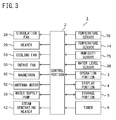
- Fig. 3 is a block diagram showing the configuration of the steam cooker 1.
- the steam cooker 1 includes a control portion 2 that controls individual portions. To the control portion 2 are connected the circulation fan 28, the heater 29, the cooling fan 53, the intake fan 55, the magnetron 50, the antenna motor 52, the water supply pump 35, the steam generating heater 42, the temperature sensors 74 and 76, the humidity sensor 75, the water level sensor 36, an operation portion 3, the display portion 4, the storage portion 5 and a timer 6.
- the operation portion 3 is provided in the door (unillustrated) of the body enclosure 10; the operation portion 3 performs an operation of selection in a cooking menu or the like.
- the display portion 4 is formed with a liquid crystal panel and the like provided in the door (unillustrated) of the body enclosure 10; the display portion 4 displays an item selected by the operation portion 3, the progress status of the cooking, the details of a notification to the user and the like.
- the storage portion 5 is formed with a ROM, a RAM and the like; the storage portion 5 stores a program for operating the steam cooker 1, a database of the cooking menu and the like, and performs temporary storage in a computation performed by the control portion 2.
- the timer 6 measures a cooking time and the total time of usage.
- the magnetron 50 and the antenna motor 52 are driven.
- the cooling fan 53 and the intake fan 55 are also driven.
- the microwaves are supplied by the magnetron 50 through the waveguide 60 into the heating chamber 20, and thus the item to be cooked 90 is heated with the microwaves.
- the cooling fan 53 makes outside air flow into the outside air inflow duct 56 through the outside air inflow port 62.
- the outside air that has flowed into the outside air inflow duct 56 cools the magnetron 50 and thus is increased in temperature, and is supplied by the intake fan 55 through the intake port 57 to the heating chamber 20.
- the intake fan 55 By the intake of the air through the intake port 57, the air within the heating chamber 20 flows through the exhaust port 58 into the exhaust duct 72, and is discharged through the open portion 73 of the ceiling surface to the outside.
- the circulation fan 28 and the heater 29 are driven.
- the air within the heating chamber 20 flows into the circulation duct 27 through the inlet 20a, and is heated by the heater 29 and is discharged through the outlets 20b to 20g. In this way, the air within the heating chamber 20 is maintained at a predetermined temperature and is circulated, and the item to be cooked 90 is cooked.
- the timer 6 detects that the cooking time has elapsed, the cooking is completed.
- an abnormally high temperature within the heating chamber 20 is detected with the temperature sensor 76, the cooking is interrupted.
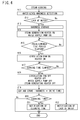
- Fig. 4 is a flowchart showing an operation of cooking (steam cooking) using steam.
- the water level sensor 36 detects the water level of the water tank 30 and the hardness.
- step #12 whether or not the amount of water in the water tank 30 is insufficient is determined.
- step #22 a notification of lack of water is provided by the display portion 4, and the process is completed. If the amount of water in the water tank 30 is sufficient, the process moves to step #13. In step #13, the hardness detected in step #11 is stored in the storage portion 5.
- step #14 the steam generating heater 42 and the water supply pump 35 are driven.
- the water in the water storage portion 31 is supplied into the housing 41 of the steam generating device 40 at a predetermined flow rate, and the steam generated by heating with the steam generating heater 42 is supplied to the heating chamber 20.
- step #15 the steam cooker 1 is placed on standby for a predetermined time period, and, when the steam fills the heating chamber 20, the process moves to step #16.
- step #16 the circulation fan 28 and the heater 29 are driven.
- the steam within the heating chamber 20 flows through the inlet 20a into the circulation duct 27, and the steam is heated by the heater 29 and is discharged through the outlets 20b to 20g.
- the steam within the heating chamber 20 is maintained at a predetermined temperature and is circulated, and the item to be cooked 90 is cooked with the saturated steam or the superheated steam.
- step #17 the steam cooker 1 is placed on standby until the cooking time elapses.
- step #18 the circulation fan 28, the heater 29, the water supply pump 35 and the steam generating heater 42 are stopped.
- step #19 a total obtained by summing the product of the water hardness stored in step #13 and the drive time of the steam generating device 40 measured by the timer 6 and a predetermined variable T is stored. Each time the cooking is performed, the variable T is stored as a value obtained by summing the previous total value of the product and the current product.
- step #20 whether or not the variable T exceeds a predetermined value indicating the cleaning time and the cleaning time has arrived is determined. Specifically, when water having a high hardness is used, even if a time period during the steam is generated is short, the cleaning time arrives, with the result that the interval of the cleaning is decreased. When water having a low hardness is used, if the time period during the steam is generated is short, the cleaning time does not arrive, with the result that the interval of the cleaning is increased.
- the process is completed whereas, if the cleaning time arrives, in step #21, a notification of the arrival of the cleaning time is provided by the display portion 4, and the process is completed.
- the display portion 4 is configured to include a notification portion that provides a notification of the cleaning time of the steam generating device 40.
- the user finds the cleaning time of the steam generating device 40, and performs a predetermined operation of cleaning the steam generating device 40 with citric acid or the like.
- the variable T is reset. Consequently, it is possible to remove the scale of the steam generating device 40 and maintain the performance.
- the hardness detection portion is provided that has a plurality of electrodes 30a to 30c which are immersed in water within the water storage portion 31 coupled to the water tank 30, and the hardness of the water within the water tank 30 is detected by the resistance between the electrodes 30a to 30c.
- the interval of cleaning of the steam generating device 40 is set shorter than an interval set when the hardness is low, and a notification of the cleaning time is provided by the display portion 4 (notification portion).
- the display portion 4 notification portion
- the water hardness may be detected by immersing the electrodes 30a to 30c in the water within the water tank 30.
- the notification of the cleaning time may be provided such as by producing sound or turning on a warning light (for example, an LED).
- step #20 since, in step #20, when the total of the product of the hardness of the water within the water tank 30 and the drive time of the steam generating device 40 exceeds the predetermined value, the cleaning time of the steam generating device 40 is determined to arrive, it is possible to accurately determine the cleaning time even if the hardness of the water stored in the water tank 30 is changed each time the cooking is performed.
Landscapes
- Engineering & Computer Science (AREA)
- Physics & Mathematics (AREA)
- Thermal Sciences (AREA)
- General Engineering & Computer Science (AREA)
- Mechanical Engineering (AREA)
- Sustainable Energy (AREA)
- Life Sciences & Earth Sciences (AREA)
- Sustainable Development (AREA)
- Fluid Mechanics (AREA)
- General Physics & Mathematics (AREA)
- Chemical & Material Sciences (AREA)
- Combustion & Propulsion (AREA)
- Electric Ovens (AREA)
- Cookers (AREA)
Abstract
Description
- The present invention relates to a steam cooker that cooks, with steam, an item to be cooked.
- A conventional steam cooker is disclosed in
patent document 1. This steam cooker includes a steam generating device for supplying steam to a heating chamber that stores an item to be cooked. In the steam generating device, a steam generating heater is provided within a housing to which water is supplied from a removable water tank. The housing is provided with a water level sensor that is formed with a self-heating heat-sensing element. - When the water tank in which tap water or the like is stored is fitted, the water is supplied from the water tank into the housing of the steam generating device. When, in the housing, a predetermined water level is achieved with the water level sensor, the water supply is stopped, and the water heated by the steam generating heater is esteamated to generate steam. The steam generated by the steam generating device is supplied to the heating chamber, and the item to be cooked within the heating chamber is cooked with the steam.
- The water supplied to the steam generating device contains impurities; the water is esteamated by heating with the steam generating heater, and scale is attached to the housing and the water level sensor. Hence, when the water level within the housing becomes lower than a predetermined water level, the water level sensor is stopped. Thus, it is possible to reduce the attachment of scale to the water level sensor and prevent the water level sensor from performing erroneous detection.
- On the other hand, when the scale is attached to the housing, the thermal conductivity thereof is reduced, the amount of steam generated is reduced and the performance of the steam generating device is reduced. Since tap water in Japan is mainly soft water, the amount of scale attached is low, and the performance is only slightly reduced in the useful life of the steam cooker (for example, 10 years).
- However, since, outside Japan, tap water or mineral water that is hard water is often supplied to the water supply tank, the performance of the steam generating device is significantly reduced by the attachment of scale. Hence, it is necessary to periodically clean, with citric acid or the like, the inside of the housing of the steam generating device. Here, a user measures, with a test paper, the hardness of water stored in the water tank, and performs an input operation to set the measured water hardness. Then, a notification of a time for cleaning the steam generating device based on an interval corresponding to the water hardness is provided to the user by display or the like, and the steam generating device is cleaned.
- Patent document 1:
JP-A-2005-337627 Fig. 1 ) - However, in the conventional steam cooker described above, in order for the user to find the time for cleaning the steam generating device, it is necessary for the user to perform complicated operations such as the measurement of the hardness and the setting. For this reason, the convenience of the steam cooker is disadvantageously reduced.
- An object of the present invention is to provide a steam cooker that can enhance convenience.
- To achieve the above object, according to the present invention, there is provided a steam cooker including: a heating chamber that stores an item to be cooked; a removable water tank; a steam generating device that includes a housing to which water is supplied from the water tank and that heats, with a steam generating heater, the water within the housing and supplies steam to the heating chamber; a hardness detection portion that includes a plurality of electrodes which are immersed in water within the water tank or a water storage portion coupled to the water tank and that detects a hardness of the water within the water tank by a resistance between the electrodes; and a notification portion that provides a notification of a cleaning time of the steam generating device, in which, when the hardness of the water within the water tank that is detected by the hardness detection portion is high, an interval of cleaning of the steam generating device is shorter than an interval set when the hardness detected by the hardness detection portion is low.
- In this configuration, the water tank storing tap water or the like is fitted, and the electrodes of the hardness detection portion are immersed in the water within the water tank or the water storage portion coupled to the water tank. The hardness of the water within the water tank is detected by the resistance between the plurality of electrodes. When the cooking is started, the water is supplied from the water tank to the housing of the steam generating device. When the water level within the housing reaches a predetermined water level, the supply of the water is stopped, and the water heated by the steam generating heater is esteamated to generate steam. The steam generated by the steam generating device is supplied to the heating chamber, and the item to be cooked within the heating chamber is cooked with the steam. When the drive time of the steam generating device reaches the cleaning time determined according to the hardness of the water within the water tank, a notification of the cleaning time is provided to a user by display, sound or the like with the notification portion. Here, when the hardness of the water within the water tank that is detected by the hardness detection portion is high, the interval of the cleaning of the steam generating device is set shorter than an interval set when the hardness detected by the hardness detection portion is low.
- According to the present invention, in the steam cooker configured as described above, the water level of the water tank is detected by continuity between the electrodes. In this configuration, when the electrodes that are immersed in the water within the water tank or the water storage portion are electrically discontinuous, the amount of water in the water tank is determined to be insufficient, and, for example, the steam cooker is placed on standby for starting the cooking.
- According to the present invention, in the steam cooker configured as described above, when the total of the product of the hardness of the water within the water tank and the drive time of the steam generating device exceeds a predetermined value, the cleaning time of the steam generating device is determined to arrive.
- According to the present invention, since a hardness detection portion includes a plurality of electrodes which are immersed in water within a water tank or a water storage portion coupled to the water tank and detects the hardness of the water within the water tank by a resistance between the electrodes, and, when the hardness of the water within the water tank is high, the interval of cleaning of the steam generating device is set shorter than an interval set when the hardness is low, and a notification of a cleaning time is provided by a notification portion, it is possible to clean the steam generating device according to the hardness of the water within the water tank without complicated operations being performed by a user. It is therefore possible to enhance the convenience of the steam cooker.
-
- [
Fig. 1 ] A front cross-sectional view showing a steam cooker according to an embodiment of the present invention; - [
Fig. 2 ] A front cross-sectional view showing a water storage portion of the steam cooker according to the embodiment of the present invention; - [
Fig. 3 ] A block diagram showing the configuration of the steam cooker according to the embodiment of the present invention; and - [
Fig. 4 ] A flowchart showing the operation of the steam cooker according to the embodiment of the present invention. - An embodiment of the present invention will be described below with reference to accompanying drawings.
Fig. 1 is a front cross-sectional view showing a steam cooker according to an embodiment of the present invention. Thesteam cooker 1 includes, within abody enclosure portion 10, aheating chamber 20 that stores an item to be cooked 90. Theheating chamber 20 is box-shaped whose front surface is open and is opened and closed by a door (unillustrated). Aheat insulator 14 is provided on the perimeter surface of theheating chamber 20, and atemperature sensor 76 is provided on the ceiling surface within theheating chamber 20. - On the left side wall of the
heating chamber 20,protrusion portions protrusion portions protrusion portions protrusion portions protrusion portions tray 21 having a placement net 22 on which the item to be cooked 90 is placed is put. - A
circulation duct 27 is provided behind theheating chamber 20. In thecirculation duct 27, there are provided aninlet 20a that is open at the middle portion of the back surface of theheating chamber 20 andoutlets circulation duct 27, there are provided a circulation fan 28 (seeFig. 3 ) and a heater 29 (seeFig. 3 ). Thecirculation fan 28 and theheater 29 are driven, and thus steam and air within theheating chamber 20 flow into thecirculation duct 27 through theinlet 20a, and they are heated and are discharged through theoutlets 20b to 20g. - Below the
heating chamber 20, there is provided an outsideair inflow duct 56 that includes acooling fan 53, awaveguide 60 and amagnetron 50. In the outsideair inflow duct 56, an outside air inflow port 62 is open in the lower surface of thebody enclosure 10, and thecooling fan 53 is arranged to face the outside air inflow port 62. Themagnetron 50 supplies microwaves into theheating chamber 20 through thewaveguide 60. Thus, it is possible to heat the item to be cooked 90 with the microwaves. In thewaveguide 60, an antenna 51 that is rotated by anantenna motor 52 is provided, and the microwaves supplied to theheating chamber 20 are made uniform. - In the right side wall of the
heating chamber 20, there are provided anintake port 57 and anexhaust port 58. In a position within the outsideair inflow duct 56 that faces theintake port 57, anintake fan 55 is provided. The outsideair inflow duct 56 is separated by aseparation plate 34 from the right upper portion of theheating chamber 20. Theexhaust port 58 communicates with anexhaust duct 72 whoseopen portion 73 is open to the upper surface of thebody enclosure 10. Theexhaust duct 72 is provided with ahumidity sensor 75 and atemperature sensor 74. - Above the
separation plate 34 on the right side of theheating chamber 20, aremovable water tank 30 is provided. Awater storage portion 31 is provided next to thewater tank 30. Thewater storage portion 31 is coupled to thewater tank 30 through acommunication passage 32 via a water stop valve (unillustrated) provided on the side of the back surface of thewater tank 30; when thewater tank 30 is fitted, the water within thewater tank 30 flows in. -
Fig. 2 shows a front cross-sectional view of thewater storage portion 31. In thewater storage portion 31, there is provided awater level sensor 36 that is immersed in the water passed from thewater tank 30 and that detects the water level. Thewater level sensor 36 haselectrodes water tank 30 is detected by continuity between theelectrodes - For example, when the
electrodes Fig. 3 ) or the like; when the notification is provided before the start of cooking, thesteam cooker 1 is placed on standby for starting the cooking. When theelectrodes 36a and 36b become electrically discontinuous, for example, the cooking is temporarily stopped. - A resistance between the
electrodes 36a and 36b of thewater level sensor 36 or between theelectrodes water tank 30 is detected. The hardness of water is indicated by the content of CaCo3; the unit thereof is ppm, mg/L or dH. Since, as the hardness of water becomes higher, its electrical conductivity is increased, its resistance is decreased. - Hence, a relationship between the hardness and the resistance is previously stored in a storage portion 5 (see
Fig. 3 ), and the hardness is derived from a resistance detected by thewater level sensor 36. Therefore, thewater level sensor 36 is configured to include a hardness detection portion that detects the hardness of water in thewater tank 30. Thewater level sensor 36 may be provided on the upper surface of thewater tank 30, and a terminal portion that makes contact with theelectrodes water tank 30 is fitted may be provided in thebody enclosure 10. - In
Fig. 1 , asteam generating device 40 is provided in an upper portion of the right side wall of theheating chamber 2. In thesteam generating device 40, asteam generating heater 42 is provided within ametallic housing 41. Awater supply pipe 33 that is extended from thewater storage portion 31 is connected to thehousing 41; adischarge port 44 that faces theheating chamber 2 is open. - A
water supply pump 35 that is provided in the path of thewater supply pipe 33 is driven, and thus the water is supplied from thewater storage portion 31 into thehousing 41. The water within thehousing 41 is heated by thesteam generating heater 42 and is thereby esteamated, and the steam is discharged through thedischarge port 44 into theheating chamber 2. Thus, it is possible to cook the item to be cooked 90 with the saturated steam or the superheated steam. -
Fig. 3 is a block diagram showing the configuration of thesteam cooker 1. Thesteam cooker 1 includes acontrol portion 2 that controls individual portions. To thecontrol portion 2 are connected thecirculation fan 28, theheater 29, the coolingfan 53, theintake fan 55, themagnetron 50, theantenna motor 52, thewater supply pump 35, thesteam generating heater 42, thetemperature sensors humidity sensor 75, thewater level sensor 36, an operation portion 3, the display portion 4, the storage portion 5 and atimer 6. - The operation portion 3 is provided in the door (unillustrated) of the
body enclosure 10; the operation portion 3 performs an operation of selection in a cooking menu or the like. The display portion 4 is formed with a liquid crystal panel and the like provided in the door (unillustrated) of thebody enclosure 10; the display portion 4 displays an item selected by the operation portion 3, the progress status of the cooking, the details of a notification to the user and the like. The storage portion 5 is formed with a ROM, a RAM and the like; the storage portion 5 stores a program for operating thesteam cooker 1, a database of the cooking menu and the like, and performs temporary storage in a computation performed by thecontrol portion 2. Thetimer 6 measures a cooking time and the total time of usage. - In the
steam cooker 1 configured as described, when cooking (range cooking) using the microwaves is started, themagnetron 50 and theantenna motor 52 are driven. The coolingfan 53 and theintake fan 55 are also driven. The microwaves are supplied by themagnetron 50 through thewaveguide 60 into theheating chamber 20, and thus the item to be cooked 90 is heated with the microwaves. - The cooling
fan 53 makes outside air flow into the outsideair inflow duct 56 through the outside air inflow port 62. The outside air that has flowed into the outsideair inflow duct 56 cools themagnetron 50 and thus is increased in temperature, and is supplied by theintake fan 55 through theintake port 57 to theheating chamber 20. By the intake of the air through theintake port 57, the air within theheating chamber 20 flows through theexhaust port 58 into theexhaust duct 72, and is discharged through theopen portion 73 of the ceiling surface to the outside. - When steam is produced from the item to be cooked 90 by the heating with the microwaves and the humidity within the
heating chamber 20 reaches a predetermined humidity, a time when the cooking is completed is determined by detection with thehumidity sensor 75. Thus, the cooking using the microwaves is completed. When an abnormally high temperature within theheating chamber 20 is detected with thetemperature sensors - When cooking (oven cooking) using a hot air is started, the
circulation fan 28 and theheater 29 are driven. The air within theheating chamber 20 flows into thecirculation duct 27 through theinlet 20a, and is heated by theheater 29 and is discharged through theoutlets 20b to 20g. In this way, the air within theheating chamber 20 is maintained at a predetermined temperature and is circulated, and the item to be cooked 90 is cooked. When thetimer 6 detects that the cooking time has elapsed, the cooking is completed. When an abnormally high temperature within theheating chamber 20 is detected with thetemperature sensor 76, the cooking is interrupted. -
Fig. 4 is a flowchart showing an operation of cooking (steam cooking) using steam. When thewater tank 30 is fitted, and the steam cooking is started, instep # 11, thewater level sensor 36 detects the water level of thewater tank 30 and the hardness. Instep # 12, whether or not the amount of water in thewater tank 30 is insufficient is determined. - If the amount of water in the
water tank 30 is insufficient, the process moves to step #22 where a notification of lack of water is provided by the display portion 4, and the process is completed. If the amount of water in thewater tank 30 is sufficient, the process moves to step #13. Instep # 13, the hardness detected instep # 11 is stored in the storage portion 5. - In
step # 14, thesteam generating heater 42 and thewater supply pump 35 are driven. Thus, the water in thewater storage portion 31 is supplied into thehousing 41 of thesteam generating device 40 at a predetermined flow rate, and the steam generated by heating with thesteam generating heater 42 is supplied to theheating chamber 20. Instep # 15, thesteam cooker 1 is placed on standby for a predetermined time period, and, when the steam fills theheating chamber 20, the process moves to step #16. - In
step # 16, thecirculation fan 28 and theheater 29 are driven. The steam within theheating chamber 20 flows through theinlet 20a into thecirculation duct 27, and the steam is heated by theheater 29 and is discharged through theoutlets 20b to 20g. In this way, the steam within theheating chamber 20 is maintained at a predetermined temperature and is circulated, and the item to be cooked 90 is cooked with the saturated steam or the superheated steam. - In
step # 17, thesteam cooker 1 is placed on standby until the cooking time elapses. When the cooking time has elapsed, instep # 18, thecirculation fan 28, theheater 29, thewater supply pump 35 and thesteam generating heater 42 are stopped. - In
step # 19, a total obtained by summing the product of the water hardness stored instep # 13 and the drive time of thesteam generating device 40 measured by thetimer 6 and a predetermined variable T is stored. Each time the cooking is performed, the variable T is stored as a value obtained by summing the previous total value of the product and the current product. Instep # 20, whether or not the variable T exceeds a predetermined value indicating the cleaning time and the cleaning time has arrived is determined. Specifically, when water having a high hardness is used, even if a time period during the steam is generated is short, the cleaning time arrives, with the result that the interval of the cleaning is decreased. When water having a low hardness is used, if the time period during the steam is generated is short, the cleaning time does not arrive, with the result that the interval of the cleaning is increased. - If the cleaning time does not arrive, the process is completed whereas, if the cleaning time arrives, in
step # 21, a notification of the arrival of the cleaning time is provided by the display portion 4, and the process is completed. That is, the display portion 4 is configured to include a notification portion that provides a notification of the cleaning time of thesteam generating device 40. In this way, the user finds the cleaning time of thesteam generating device 40, and performs a predetermined operation of cleaning thesteam generating device 40 with citric acid or the like. Here, the variable T is reset. Consequently, it is possible to remove the scale of thesteam generating device 40 and maintain the performance. - In the present embodiment, the hardness detection portion is provided that has a plurality of electrodes 30a to 30c which are immersed in water within the
water storage portion 31 coupled to thewater tank 30, and the hardness of the water within thewater tank 30 is detected by the resistance between the electrodes 30a to 30c. When the hardness of the water within thewater tank 30 is high, the interval of cleaning of thesteam generating device 40 is set shorter than an interval set when the hardness is low, and a notification of the cleaning time is provided by the display portion 4 (notification portion). Thus, it is possible to clean thesteam generating device 40 according to the hardness of the water within thewater tank 30 without complicated operations being performed by the user. It is therefore possible to enhance the convenience of thesteam cooker 1. - As described above, the water hardness may be detected by immersing the electrodes 30a to 30c in the water within the
water tank 30. The notification of the cleaning time may be provided such as by producing sound or turning on a warning light (for example, an LED). - Since the water level of the
water tank 30 is detected by continuity between the electrodes 30a to 30c, it is not necessary to provide the hardness detection portion in addition to thewater level sensor 36, and thus it is possible to reduce the cost of thesteam cooker 1. - Since, in
step # 20, when the total of the product of the hardness of the water within thewater tank 30 and the drive time of thesteam generating device 40 exceeds the predetermined value, the cleaning time of thesteam generating device 40 is determined to arrive, it is possible to accurately determine the cleaning time even if the hardness of the water stored in thewater tank 30 is changed each time the cooking is performed. - With the present invention, it is possible to utilize a steam cooker that cooks, with steam, an item to be cooked.
-
- 1
- Steam cooker
- 2
- Control portion
- 3
- Operation portion
- 4
- Display portion
- 5
- Storage portion
- 6
- Timer
- 10
- Body enclosure
- 20
- Heating chamber
- 20a
- Inlet
- 20b to 20g
- Outlets
- 21 1
- Tray
- 27
- Circulation duct
- 28
- Circulation fan
- 29
- Heater
- 30
- Water tank
- 31
- Water storage portion
- 35
- Water supply pump
- 36
- Water level sensor (hardness detection portion)
- 36a to 36c
- Electrodes
- 40
- Steam generating device
- 41
- Housing
- 42
- Steam generating heater
- 44
- Discharge port
- 50
- Magnetron
- 51
- Antenna
- 53
- Cooling fan
- 55
- Intake fan
- 56
- Outside air inflow duct
- 57
- Intake port
- 58
- Exhaust port
- 60
- Waveguide
- 72
- Exhaust duct
- 74 and 76
- Temperature sensors
- 75
- Humidity sensor
- 90
- Item to be cooked
Claims (3)
- A steam cooker comprising:a heating chamber that stores an item to be cooked;a removable water tank;a steam generating device that includes a housing to which water is supplied from the water tank and that heats, with a steam generating heater, the water within the housing and supplies steam to the heating chamber;a hardness detection portion that includes a plurality of electrodes which are immersed in water within the water tank or a water storage portion coupled to the water tank and that detects a hardness of the water within the water tank by a resistance between the electrodes; anda notification portion that provides a notification of a cleaning time of the steam generating device,wherein, when the hardness of the water within the water tank that is detected by the hardness detection portion is high, an interval of cleaning of the steam generating device is shorter than an interval set when the hardness detected by the hardness detection portion is low.
- The steam cooker of claim 1,
wherein a water level of the water tank is detected by continuity between the electrodes. - The steam cooker of claim 1 or 2,
wherein, when a total of a product of the hardness of the water within the water tank and a drive time of the steam generating device exceeds a predetermined value, the cleaning time of the steam generating device is determined to arrive.
Applications Claiming Priority (2)
| Application Number | Priority Date | Filing Date | Title |
|---|---|---|---|
| JP2009139722A JP4617386B2 (en) | 2009-06-11 | 2009-06-11 | Steam cooker |
| PCT/JP2010/059821 WO2010143678A1 (en) | 2009-06-11 | 2010-06-10 | Vapor cooker |
Publications (2)
| Publication Number | Publication Date |
|---|---|
| EP2442025A1 true EP2442025A1 (en) | 2012-04-18 |
| EP2442025A4 EP2442025A4 (en) | 2013-01-16 |
Family
ID=43308933
Family Applications (1)
| Application Number | Title | Priority Date | Filing Date |
|---|---|---|---|
| EP10786209A Withdrawn EP2442025A4 (en) | 2009-06-11 | 2010-06-10 | Vapor cooker |
Country Status (5)
| Country | Link |
|---|---|
| US (1) | US8674267B2 (en) |
| EP (1) | EP2442025A4 (en) |
| JP (1) | JP4617386B2 (en) |
| CN (1) | CN102460011B (en) |
| WO (1) | WO2010143678A1 (en) |
Cited By (2)
| Publication number | Priority date | Publication date | Assignee | Title |
|---|---|---|---|---|
| FR3014663A1 (en) * | 2013-12-13 | 2015-06-19 | Seb Sa | ELECTRICAL HEATING AND / OR COOKING APPARATUS FOR STEAM FOOD |
| DE102011081703B4 (en) * | 2011-08-29 | 2017-05-24 | BSH Hausgeräte GmbH | Method for operating a household appliance with a water heater and domestic appliance with instantaneous water heater |
Families Citing this family (20)
| Publication number | Priority date | Publication date | Assignee | Title |
|---|---|---|---|---|
| CA2255599C (en) | 1996-04-25 | 2006-09-05 | Bioarray Solutions, Llc | Light-controlled electrokinetic assembly of particles near surfaces |
| US9709559B2 (en) | 2000-06-21 | 2017-07-18 | Bioarray Solutions, Ltd. | Multianalyte molecular analysis using application-specific random particle arrays |
| US7262063B2 (en) | 2001-06-21 | 2007-08-28 | Bio Array Solutions, Ltd. | Directed assembly of functional heterostructures |
| CA2497740C (en) | 2001-10-15 | 2011-06-21 | Bioarray Solutions, Ltd. | Multiplexed analysis of polymorphic loci by probe elongation-mediated detection |
| AU2003298655A1 (en) | 2002-11-15 | 2004-06-15 | Bioarray Solutions, Ltd. | Analysis, secure access to, and transmission of array images |
| CA2539824C (en) | 2003-09-22 | 2015-02-03 | Xinwen Wang | Surface immobilized polyelectrolyte with multiple functional groups capable of covalently bonding to biomolecules |
| CA2544041C (en) | 2003-10-28 | 2015-12-08 | Bioarray Solutions Ltd. | Optimization of gene expression analysis using immobilized capture probes |
| US7848889B2 (en) | 2004-08-02 | 2010-12-07 | Bioarray Solutions, Ltd. | Automated analysis of multiplexed probe-target interaction patterns: pattern matching and allele identification |
| CN104246374B (en) | 2012-03-19 | 2018-01-02 | 松下电器产业株式会社 | Heating device |
| US9357787B2 (en) | 2013-06-27 | 2016-06-07 | Middleby Marshall Holdings Llc | Forced moisture evacuation for rapid baking |
| CN105030049A (en) * | 2015-08-05 | 2015-11-11 | 广东美的厨房电器制造有限公司 | Steam cooking apparatus and water quality detection method for steam cooking apparatus |
| WO2017116352A1 (en) * | 2015-12-29 | 2017-07-06 | Arcelik Anonim Sirketi | An oven comprising a water tank |
| CN108591983B (en) * | 2018-04-28 | 2020-07-07 | 广东美的厨房电器制造有限公司 | Steam generating system and scale detection method thereof |
| CN110179350A (en) * | 2019-05-21 | 2019-08-30 | 华帝股份有限公司 | Water tank water treatment method, water tank structure and steam cooking device |
| CN111387807B (en) * | 2020-05-11 | 2021-11-09 | 珠海格力电器股份有限公司 | Cooking appliance and cooking control method, device and system thereof |
| CN113349696B (en) * | 2021-06-02 | 2024-07-30 | 华帝股份有限公司 | Method and device for descaling, computer equipment and readable storage medium |
| CN113925340A (en) * | 2021-11-04 | 2022-01-14 | 珠海格力电器股份有限公司 | Descaling device and method for steam generator and steam oven |
| CN114424892B (en) * | 2022-02-28 | 2023-06-20 | 杭州老板电器股份有限公司 | Scale detection method for steam cooking equipment and steam cooking equipment |
| CN117122209A (en) * | 2022-05-18 | 2023-11-28 | 深圳市虎一科技有限公司 | Cleaning method and system for cooking device |
| CN117307140A (en) * | 2023-10-09 | 2023-12-29 | 武汉工程大学 | A brine well liquid level probe and a brine well liquid level measuring device |
Family Cites Families (20)
| Publication number | Priority date | Publication date | Assignee | Title |
|---|---|---|---|---|
| US4096369A (en) * | 1975-11-20 | 1978-06-20 | Matsushita Electric Industrial Co., Ltd. | Microwave oven |
| JPS58194747U (en) * | 1982-06-18 | 1983-12-24 | 大畠 隆 | processed food storage |
| US4695711A (en) * | 1984-12-24 | 1987-09-22 | Robershaw Controls Company | Electrically operated appliance controls and methods of making the same |
| CN2030323U (en) | 1988-05-18 | 1989-01-04 | 王洪璞 | Automatic monitor of specific conductivity and hardness of boiler water |
| DE19541719A1 (en) * | 1995-11-09 | 1997-05-15 | Foron Hausgeraete Gmbh | Determining harness of water used as solvent |
| US5680810A (en) * | 1996-08-09 | 1997-10-28 | Sham; John C. K. | Steam toaster oven |
| JP3553742B2 (en) * | 1996-09-03 | 2004-08-11 | 松下電器産業株式会社 | Microwave heating equipment |
| EP0952400B1 (en) * | 1996-09-03 | 2003-04-09 | Matsushita Electric Industrial Co., Ltd. | Microwave heating device |
| KR100402495B1 (en) * | 2000-11-30 | 2003-10-22 | 주식회사 엘지이아이 | A heater system for micro wave oven |
| US6818867B2 (en) * | 2001-06-09 | 2004-11-16 | Braun Gmbh | Method for heating liquid in an electric kettle |
| US6833032B1 (en) * | 2002-11-05 | 2004-12-21 | Blodgett Holdings, Inc. | Automatic deliming process |
| US8424345B2 (en) * | 2002-11-28 | 2013-04-23 | Lg Electronics Inc. | Washing machine, conductivity sensor in washing machine, and controlling method of the same |
| CN1226101C (en) | 2002-12-09 | 2005-11-09 | 韩平 | Automatic control system and method for floating-bed type sodium ion exchange |
| JP3800190B2 (en) * | 2003-03-12 | 2006-07-26 | 松下電器産業株式会社 | High-frequency heating device with steam generation function |
| JP2004138381A (en) | 2003-12-19 | 2004-05-13 | Matsushita Electric Ind Co Ltd | Cooking device |
| JP4405315B2 (en) * | 2004-05-28 | 2010-01-27 | シャープ株式会社 | Steam cooker |
| US7709265B2 (en) * | 2005-03-24 | 2010-05-04 | Johnsondiversey, Inc. | Method and system for measuring water hardness |
| JP2008032266A (en) * | 2006-07-26 | 2008-02-14 | Sharp Corp | Steam generator and cooking device equipped with the same |
| JP5013063B2 (en) | 2006-12-26 | 2012-08-29 | 三浦工業株式会社 | Supplying water for boiler feed water |
| WO2008078668A1 (en) * | 2006-12-26 | 2008-07-03 | Miura Co., Ltd. | Method of feeding makeup water for boiler water supply |
-
2009
- 2009-06-11 JP JP2009139722A patent/JP4617386B2/en not_active Expired - Fee Related
-
2010
- 2010-06-10 US US13/322,254 patent/US8674267B2/en not_active Expired - Fee Related
- 2010-06-10 WO PCT/JP2010/059821 patent/WO2010143678A1/en not_active Ceased
- 2010-06-10 EP EP10786209A patent/EP2442025A4/en not_active Withdrawn
- 2010-06-10 CN CN201080025459.7A patent/CN102460011B/en not_active Expired - Fee Related
Cited By (3)
| Publication number | Priority date | Publication date | Assignee | Title |
|---|---|---|---|---|
| DE102011081703B4 (en) * | 2011-08-29 | 2017-05-24 | BSH Hausgeräte GmbH | Method for operating a household appliance with a water heater and domestic appliance with instantaneous water heater |
| FR3014663A1 (en) * | 2013-12-13 | 2015-06-19 | Seb Sa | ELECTRICAL HEATING AND / OR COOKING APPARATUS FOR STEAM FOOD |
| EP2893853A1 (en) * | 2013-12-13 | 2015-07-15 | Seb S.A. | Electrical device for heating and/or cooking food with steam |
Also Published As
| Publication number | Publication date |
|---|---|
| EP2442025A4 (en) | 2013-01-16 |
| WO2010143678A1 (en) | 2010-12-16 |
| CN102460011A (en) | 2012-05-16 |
| CN102460011B (en) | 2014-11-05 |
| JP2010286159A (en) | 2010-12-24 |
| US8674267B2 (en) | 2014-03-18 |
| JP4617386B2 (en) | 2011-01-26 |
| US20120091118A1 (en) | 2012-04-19 |
Similar Documents
| Publication | Publication Date | Title |
|---|---|---|
| US8674267B2 (en) | Steam cooker | |
| US8420983B2 (en) | Vapor cooker | |
| EP2259703B1 (en) | A multi-purpose cooking device through heating of a water bath | |
| US20120017770A1 (en) | Cooking appliance | |
| CN101579190A (en) | An electric cooker and its method for autonomously detecting dry-burning state | |
| EP2088370A1 (en) | Cooking oven comprising steam generating system | |
| EP1956299A1 (en) | Heating cooker | |
| KR20090101046A (en) | Heating cooker | |
| CN112120527B (en) | Control method of cooking appliance | |
| JP5052988B2 (en) | Steam cooker | |
| JP4398798B2 (en) | Steam cooker | |
| JP2017062103A (en) | Steam cooker | |
| JP5797729B2 (en) | Steam cooker | |
| JP6043414B2 (en) | Steam cooker | |
| JP5486648B2 (en) | Steam cooker | |
| JP4987635B2 (en) | Steam cooker | |
| JP2009041818A (en) | Steam cooker | |
| JP2011163573A (en) | Steam cooker | |
| JP6335670B2 (en) | Cooker | |
| JP2012107866A (en) | Steam cooker | |
| JP2025104950A (en) | heating cooker | |
| JP2008256289A (en) | Steam cooker | |
| JP2004024617A (en) | Rice cooker | |
| JP2005340119A (en) | Electromagnetic cooker | |
| JP2009041820A (en) | Cooker |
Legal Events
| Date | Code | Title | Description |
|---|---|---|---|
| PUAI | Public reference made under article 153(3) epc to a published international application that has entered the european phase |
Free format text: ORIGINAL CODE: 0009012 |
|
| 17P | Request for examination filed |
Effective date: 20111128 |
|
| AK | Designated contracting states |
Kind code of ref document: A1 Designated state(s): AL AT BE BG CH CY CZ DE DK EE ES FI FR GB GR HR HU IE IS IT LI LT LU LV MC MK MT NL NO PL PT RO SE SI SK SM TR |
|
| DAX | Request for extension of the european patent (deleted) | ||
| A4 | Supplementary search report drawn up and despatched |
Effective date: 20121219 |
|
| RIC1 | Information provided on ipc code assigned before grant |
Ipc: F22B 37/56 20060101ALI20121213BHEP Ipc: F22B 1/28 20060101AFI20121213BHEP Ipc: F24C 15/32 20060101ALI20121213BHEP Ipc: G01F 23/24 20060101ALI20121213BHEP |
|
| STAA | Information on the status of an ep patent application or granted ep patent |
Free format text: STATUS: THE APPLICATION HAS BEEN WITHDRAWN |
|
| 18W | Application withdrawn |
Effective date: 20160823 |