EP2441982B1 - Train épicycloïdal doté d'un premier ensemble de roues épicycloïdales et d'un deuxième ensemble de roues épicycloïdales, ainsi qu'une unité de construction dans un tel train épicycloïdal - Google Patents
Train épicycloïdal doté d'un premier ensemble de roues épicycloïdales et d'un deuxième ensemble de roues épicycloïdales, ainsi qu'une unité de construction dans un tel train épicycloïdal Download PDFInfo
- Publication number
- EP2441982B1 EP2441982B1 EP20110172517 EP11172517A EP2441982B1 EP 2441982 B1 EP2441982 B1 EP 2441982B1 EP 20110172517 EP20110172517 EP 20110172517 EP 11172517 A EP11172517 A EP 11172517A EP 2441982 B1 EP2441982 B1 EP 2441982B1
- Authority
- EP
- European Patent Office
- Prior art keywords
- planetary
- bearing plates
- gears
- planet
- bearing
- Prior art date
- Legal status (The legal status is an assumption and is not a legal conclusion. Google has not performed a legal analysis and makes no representation as to the accuracy of the status listed.)
- Not-in-force
Links
Images


Classifications
-
- F—MECHANICAL ENGINEERING; LIGHTING; HEATING; WEAPONS; BLASTING
- F16—ENGINEERING ELEMENTS AND UNITS; GENERAL MEASURES FOR PRODUCING AND MAINTAINING EFFECTIVE FUNCTIONING OF MACHINES OR INSTALLATIONS; THERMAL INSULATION IN GENERAL
- F16H—GEARING
- F16H57/00—General details of gearing
- F16H57/08—General details of gearing of gearings with members having orbital motion
- F16H57/082—Planet carriers
Definitions
- the invention relates to a planetary drive at least with a first set of planetary gears, with a second set of planetary gears, with at least one common for both planetary gear planet carrier and a ring gear, wherein pairs of a planetary gear of the first set and a planetary gear of the second set are in meshing engagement. Furthermore, the invention relates to a separately preassembled to the planet carrier assembly from at least the bearing plate and a pair of planetary gears.
- the JP1-6544 U is regarded as the nearest state of the art.
- Such a planetary drive is in DE 40 29 373 C2 described in more detail.
- Such planetary gears are used for example in planetary gears, in which the planetary gears of a first set with the internal teeth of a ring gear and the planet gears of a second set are in meshing engagement with a sun gear. In each case a planetary gear of the first set is in mesh with a planetary gear of the second set and forms a pair.
- pairs in generic planetary gears usually three or more pairs are arranged distributed on the circumference of the sun gear.
- simple planetary gears in which a single set of planetary gears is meshing with a sun gear and a ring gear at the same time, so the planetary gear of the species considered on another planetary stage.
- other translations and thus numbers of teeth are possible.
- the generic planetary gears are therefore often used in coupling gears instead of several coupled simple planetary gears, because instead of their axially short build and because the speeds of the planetary gears and thus the speeds in the bearings of the planetary gears can be reduced.
- the generic planetary gear are provided in so-called reducers with Ravigneaux sets, with which also several coupled simple planetary gears can be replaced.
- Ravigneaux sets are axially short. With them, different operating states can be switched by detecting or braking the shafts of the planetary gear.
- the classic Ravigneaux set has two different sized sun gears.
- the first planet gears of a first planetary gear set are so-called long planetary gears, with the internal teeth of a ring gear, with the large of the sun gears and planetary gears of a second planetary gear set meshing.
- Planetary gears of the second planetary gear set mesh with the smaller of the sun gears and at the same time with the planet gears of the first planetary gear set.
- Gearbox housings are often made of light metal alloys for weight reduction. Such arrangements put in planetary gears of the generic type due to the higher thermal expansion coefficient of the light metal housing against the Planetenziern-, bolts and their bearings made of steel only partially, because due to the different thermal expansion of the components during driving the quality of the meshing can not always be guaranteed.
- the object of the invention is therefore to provide planetary bearings for generic planetary gears, in particular for planetary gears in independent electric motor driven drive units for motor vehicles, which are able to cope with the particularly high demands at high speeds of the planet gears.
- the planetary drive has at least two sets of planet gears.
- Each planetary gear of a set is assigned in each case a planetary gear of the other set so that these planetary gears form a pair with each other in meshing engagement.
- At least one pair, but preferably all of the pairs of meshing gears of the first and second sets are rotatable about an axially aligned rotation axis as a pair or together with one or more other pairs relative to the planet carrier and to a bearing plate, respectively one held to the planet carrier separate bearing plate.
- the pre-assembled with the respective pair, with the planet pins and the bearings and thrust washers to a unit bearing plate is held at least circumferentially around the central axis relatively immobile to the planet carrier.
- the bearing plate can be positively anchored to the respective planet carrier so that this assembly is rotationally fixed to the planet carrier associated with an axis of rotation of the planet carrier.
- the assembly is clipped to the planet carrier or plugged into this or at least as inserted into a corresponding receptacle of the planet carrier and preferably screwed or riveted to the planet carrier.
- the invention also relates to assemblies of a pair of planetary gears.
- the planet gears of a pair are provided with at least one bearing plate, preferably in a housing of two bearing plates, from the planet pins or planet pins, from the planet or pin bearings and from the Thrust washers pre-assembled as assembly / module.
- Such units can be used within a planetary drive but also in a planetary gear with several of the planetary gears according to the modular system.
- the housing of this unit is formed for example by a two-piece planet carrier or by a combination of the ring gear with the planet carrier.
- the invention accordingly also relates to planetary gears, transmissions with such planetary gears and differentials, which are designed as Ravigneaux sets.
- the invention also relates to a drive unit with at least one electric motor and a differential, in which at least one planetary drive according to the invention is arranged between the electric motor and the differential, wherein the electric motor and the differential are operatively connected to each other via the planetary drive.
- the components of the planetary drive can be assembled according to the modular principle. Any number of planetary gear sets can be easily mounted. The high cost of assembly, storage and transport of individual components is eliminated. The costs for the production of the planetary drives are low.
- assemblies / modules are in themselves relatively rigid units, with which the entire planetary drive can be made torsionally stiff. This is particularly important in the application of such modules in the initially described lightweight differentials with housings made of sheet metal.
- the use of such modules in light metal planetary carriers is advantageous, so that the meshing of the planetary pairs is unaffected by effects of differential thermal expansion.
- the bearing plates such as the rolling bearings, planet pins and planet gears are made of steel and thus have the same coefficients of thermal expansion.
- the seat of the rolling bearings in a bearing plate made of steel in this case is safer than in a planet carrier made of light metal.
- An embodiment of the invention provides that the respective preassembled to the unit, the pair planet gears separately to the planet carrier axially, left and right bordered by a bearing plate, rotatably supported between two of the bearing plates about its own axis of rotation and held in meshing engagement with each other.
- These two bearing plates preferably form a housing, and are therefore designed, for example, shell-shaped and connected to the other bearing plate.
- the toothing stands out so far out of the housing that at least part of a toothing of the first planet gear and a part of a toothing of the second planet gear are freely accessible from the outside so far that secure tooth engagement with ring gears and sun gears are hedged.
- Embodiments of the invention provide that the planetary gears are rotatably mounted with pins in the bearing plate.
- a planet gear has either one or two pin designed as a journal.
- the respective shaft journal is either einmaterialig formed with the planet or attached thereto.
- the pins to the planet gear separate planet pins, on each of which at least one planetary gear of a pair is rotatably mounted.
- An embodiment of the invention provides that the planet pin is mounted on both sides and preferably on both sides, each with at least one rolling bearing.
- the planet gears are also mounted on the planet pins by means of at least one rolling bearing.
- An embodiment of the invention provides that the bearing type with which the planet gear is mounted on the respective planet pins, a different type of bearing, than that of another bearing, with which one planet pin is mounted in the bearing plate.
- Rolling bearings are single or multi-row bearings with balls, rollers or needles or a mixture of balls and rollers.
- Multi-row means that at least two rows of rolling elements of the respective rolling bearing are arranged radially concentrically with respect to one another and / or at least two rows of rolling elements are arranged next to one another in the axial direction about the same axis of rotation. Needles are rolling with a ratio of roll length to the diameter of the roll> 2.5.
- Different bearing types are accordingly ball bearings, roller or needle roller bearings or mixed forms of the aforementioned types of bearings.
- Different bearing types can also be defined by different numbers of rolling elements or by different numbers of rows of identical rolling elements.
- the invention is particularly suitable for use electric drive units, since electric motors themselves have high drive speeds. There are therefore depending on the design of the transmission in the individual planetary gears of the planetary drive high speeds expected to be reduced by means of the invention to half the speeds of a generic and up to a quarter of a simple planetary drive the same size.
- the advantage of this embodiment of the invention lies in the improvement of the efficiency of the planetary bearings and thus of the planetary drive.
- the effort for the lubrication of the individual bearings can be reduced because the speeds in the individual bearings are lower.
- the planetary pin will rotate due to the bearing with rolling bearings in the planet carrier. This quartered the relative speed in the planetary bearings over a simple planetary drive of the prior art and halved approximately once again compared to the generic state of the art.
- the limit speeds of the bearings are reduced and thus the speed characteristics lower.
- Full roll sets are rolling bearings in which the rolls without spacers in the circumferential direction are lined up. Such rolling bearings are inexpensive to produce, since only the number of rolling elements and packaging is needed for this. However, these bearings are for use at high Speeds not suitable because the rolling elements collide and extremely rub against each other and thus wear prematurely. In addition, the bearings heat at high speeds inadmissible.
- the planet carrier 13 is in the with FIG. 11a illustrated embodiment of the invention in one piece and solid, for example, made of steel or a light metal alloy.
- the planet carrier 13 has two cylindrical receptacles 13c, in each of which a collar 2a of the bearing plate 2 is inserted.
- the bearing plate 2 is at least circumferentially held about the rotational axis 13a of the respective planetary carrier 13 relatively immovably to the planet carrier 13 in which it sits with the coils 2a by means of press fit or fit in the receptacles 13c and / or screwed with screws 21 to the planet carrier 13 is.
- the bearing plate 3 has the collars 3a, which are axially concentric with the collars 2a.
- the bearing plates 2 and 3 are connected to each other, for example by riveting.
- the respective collar 2a or 3a is a bearing seat for each rolling bearing 18 of the bearing type of a ball bearing.
- the pins 20 in the form of planet pins 9 and 10 are rotatably mounted in the bearing plates 2 and 3.
- On the planetary pin 9 is a respective planetary gear 5 and the planetary pin 10 by means of a rolling bearing 19 each a planetary gear 6 about the axes of rotation 5a and 6a relative to the bearing plates 2 and 3 and to the planet carrier 13 by means of a respective rolling bearing.
- the rolling bearings 19 are of the bearing type needle roller bearing with two rows 19a and 19b needles. The needles are guided in cages 19c.
- the planet carrier 13 is in the with FIG. 11b illustrated embodiment of the invention in one or two parts of sheet steel, with only the axial left half of the image 13b of the planet carrier 13 is visible in the image.
- the planet carrier 13 has two cylindrical receptacles 13c, in each of which a collar 2a of the bearing plate 2 is inserted.
- the bearing plate 3 has the collars 3a, which are axially concentric with the collars 2a.
- the bearing plates 2 and 3 are connected to each other, for example, by rivets 22 and the assembly 1 is screwed to the planet carrier 13.
- the respective collar 2a or 3a is a bearing seat for each rolling bearing 18 of the bearing type of a ball bearing.
- the pins 20 in the form of planet pins 9 and 10 are rotatably mounted in the bearing plates 2 and 3.
- On the planetary pin 9 is a respective planetary gear 5 and the planetary pin 10 by means of a rolling bearing 19 each a planetary gear 6 about the axes of rotation 5a and 6a relative to the bearing plates 2 and 3 and to the planet carrier 13 by means of a respective rolling bearing.
- the rolling bearings 19 are of the bearing type needle roller bearing with two rows 19a and 19b needles. The needles are guided in cages 19c.
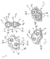
- FIGS. 8, 9 and 10 show a planetary drive 16, in which, as in the planetary drive 4, three of the units 1 are installed.
- the FIGS. 8 and 9 show the planetary gear 16 in different views, from which it can be seen that this is formed from a planet carrier 17 a ring gear 7 and a sun gear 8.
- Each of the structural units 1 is made up of two bearing plates 2 and 3, in each case one planetary gear 5 of a first set 14 three planetary gears 5, each a planetary gear 6 of a second set 15 of three planet gears 6 and planet pins 9 and 10 are formed.
- the planet carrier 17 is formed in two parts from two halves 17a and 17b, as shown FIG. 10 , A representation of the planetary drive 16 in section along the axes of rotation 5a and 6a along the line X - X from FIG. 8 , shows.
- Each of the halves 17a and 17b has two cylindrically shaped receptacles 17c, in each of which a collar 2a or 3a of one of the bearing plates 2 and 3 of the axially enclosed by the halves 17a and 17b each unit 1 fits snugly or press fit, so that the Bearing plates 2 and 3 at least circumferentially about an axis of rotation 17d of the respective planet carrier 17 is held relatively immovably to the planet carrier 17.
- the respective collar 2a or 3a is a bearing seat for each rolling bearing 18 of the bearing type of a ball bearing.
- the pins 20 in the form of planet pins 9 and 10 are rotatably mounted in the bearing plates 2 and 3.
- On the planetary pin 9 is a respective planetary gear 5 and the planetary pin 10 by means of a roller bearing 19 each a planetary gear 6 about the rotation axes 5a and 6a relative to the bearing plates 2 and 3 and to the planet carrier 17 by means of a respective rolling bearing 19.
- the rolling bearings 19 are of the bearing type needle roller bearing with two rows 19a and 19b needles. The needles are guided in cages 19c.
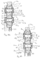
- FIGS. 12 and 13 show possible alternative embodiments of a structural unit 23 or 28 in sections along the axes of rotation 24a and 25a and 29a and 30a.
- the assembly 23 after FIG. 12 is formed of a bearing plate 26 and a bearing plate 27, planet pins 9 and 10 and planetary gears 24 and 25.
- Each of the bearing plates 26 and 27 has two cylindrical receptacles 26a and 27a, in each of which a pin 20 in the form of a planetary pin 9 and a planetary pin 10 is rotatably mounted slidably.
- the bearing plates 26 and 27 are interconnected by rivets 22.
- On the planetary pin 9 is ever a planetary gear 24 and the planetary pin 10 per a planetary gear 25 to the rotation axes 24a and 25a are mounted relative to the bearing plates 26 and 27 so as to be relatively rotatable.
- the assembly 28 after FIG. 13 is formed of a bearing plate 26 and a bearing plate 27, shaft journals 31 and planetary gears 29 and 30.
- Each of the bearing plates 26 and 27 has two cylindrical receptacles 26a and 27a, in each of which a pin 20 in the form of a shaft journal 31 is rotatably mounted slide.
- the bearing plates 26 and 27 are interconnected by rivets 22.
- Planet wheels 29 and 30 each have in the image axially to the left and right each one of the shaft journals 31, which are integrally formed with the planetary gears 29 and 30 respectively.
Landscapes
- Engineering & Computer Science (AREA)
- General Engineering & Computer Science (AREA)
- Mechanical Engineering (AREA)
- Retarders (AREA)
Claims (9)
- Train épicycloïdal (4, 16) comprenant au moins un premier train (14) de satellites (5), un deuxième train (15) de satellites (6), au moins un porte-satellites (13, 17) commun aux deux trains planétaires (14, 15) et une couronne dentée (7), chaque satellite (5) du premier train (14) formant avec un satellite (6) du deuxième train (15) une paire en engagement denté mutuel, et les satellites (5, 6) de chaque paire étant montés séparément des porte-satellites (13, 17) axialement entre deux plateaux de palier (2, 3) séparés du porte-satellites (13, 17) de manière à pouvoir tourner autour de l'axe de rotation respectif propre (5a, 6a) et étant disposés en engagement denté les uns avec les autres, caractérisé en ce que les satellites (5, 6) d'au moins une des paires sont montés par rapport au porte-satellites (13, 17) à chaque fois de manière à pouvoir tourner autour d'un axe de rotation orienté axialement (5a, 6a) et en engagement denté mutuel de manière à pouvoir tourner avec des tourillons (20) dans les plateaux de palier (2, 3, 26, 27) et étant maintenus en l'occurrence sur les plateaux de palier (2, 3), au moins l'un des plateaux de palier (2, 3) sur lesquels est maintenue la paire étant fixé sur le porte-satellites (13, 17) au moins de manière orientée circonférentiellement autour d'un axe de rotation (13a, 17d) du porte-satellites respectif (13, 17) de manière relativement immobile par rapport au porte-satellites (13, 17).
- Train épicycloïclal selon la revendication 1, caractérisé en ce que chacune des paires est à chaque fois maintenue entre deux plateaux de palier (2, 3) sur les plateaux de palier (2, 3).
- Train épicycloïdal selon la revendication 1, caractérisé en ce que les plateaux de palier sont reliés l'un à l'autre.
- Train épicycloïdal selon la revendication 1, caractérisé en ce que les satellites (5, 6) de chaque paire sont montés séparément du porte-satellites (13, 17) axialement entre deux des plateaux de palier (2, 3) séparés du porte-satellites (13, 17) de manière à pouvoir tourner autour de l'axe de rotation respectif propre (5a, 6a) et sont maintenus en engagement denté les uns avec les autres au niveau de chacun des deux plateaux de palier (2, 3) et en ce que les deux plateaux de palier (2, 3) sont fixés sur le porte-satellites (13, 17).
- Train épicycloïdal selon la revendication 4, caractérisé en ce qu'au moins l'un des plateaux de palier (2, 3) est configuré en forme de coque et est relié à l'autre plateau de palier (2, 3) pour former un boîtier et renferme la paire de satellites (5, 6) de telle sorte qu'au moins une partie d'une denture (5b) du premier satellite (5) et une partie d'une denture (6b) du deuxième satellite (6) soient librement accessibles depuis l'extérieur.
- Train épicycloïdal selon la revendication 5, caractérisé en ce que les deux plateaux de palier (2, 3) sont réalisés en forme de coque et sont reliés l'un à l'autre.
- Unité structurelle (1) pour un train épicycloïdal (4, 16) selon la revendication 1, formée d'au moins deux plateaux de palier (2, 3) et d'une paire de satellites (5, 6, 24, 25, 29, 30) en engagement denté, les satellites (5, 6, 24, 25, 29, 30) étant disposés entre les plateaux de palier (2, 3) et étant montés de manière à pouvoir tourner avec des tourillons (20) dans les plateaux de palier (2, 3, 26, 27), et l'unité structurelle (1) étant prémontée séparément du porte-satellites (13, 17).
- unité structurelle (1) selon la revendication 7, caractérisée en ce que les tourillons (20) sont des tourillons d'arbre (21) réalisés sur le satellite respectif (29, 30) et saillant axialement.
- Unité structurelle (1) selon la revendication 7, caractérisée en ce que les tourillons (20) sont des axes de satellite (9, 10) sur lesquels est à chaque fois monté à rotation au moins un satellite (5, 6, 24, 25) d'une paire.
Applications Claiming Priority (1)
| Application Number | Priority Date | Filing Date | Title |
|---|---|---|---|
| DE201010048824 DE102010048824A1 (de) | 2010-10-18 | 2010-10-18 | Planetentrieb mit einem ersten Satz Planetenräder und mit einem zweiten Satz Planetenräder und eine Baueinheit in einem derartigen Planetentrieb |
Publications (2)
| Publication Number | Publication Date |
|---|---|
| EP2441982A1 EP2441982A1 (fr) | 2012-04-18 |
| EP2441982B1 true EP2441982B1 (fr) | 2013-06-05 |
Family
ID=45474493
Family Applications (1)
| Application Number | Title | Priority Date | Filing Date |
|---|---|---|---|
| EP20110172517 Not-in-force EP2441982B1 (fr) | 2010-10-18 | 2011-07-04 | Train épicycloïdal doté d'un premier ensemble de roues épicycloïdales et d'un deuxième ensemble de roues épicycloïdales, ainsi qu'une unité de construction dans un tel train épicycloïdal |
Country Status (2)
| Country | Link |
|---|---|
| EP (1) | EP2441982B1 (fr) |
| DE (1) | DE102010048824A1 (fr) |
Families Citing this family (1)
| Publication number | Priority date | Publication date | Assignee | Title |
|---|---|---|---|---|
| DE102013226526A1 (de) * | 2013-12-18 | 2015-06-18 | Zf Friedrichshafen Ag | Bolzensitz mit optimierter Druckverteilung |
Family Cites Families (7)
| Publication number | Priority date | Publication date | Assignee | Title |
|---|---|---|---|---|
| JPH051718Y2 (fr) * | 1987-10-15 | 1993-01-18 | ||
| FR2644859B1 (fr) * | 1989-03-24 | 1991-07-12 | Rapid Sa | Dispositif elastique de maintien sensiblement sans jeux de l'axe de rotation d'au moins un element mecanique tournant dans ou sur un autre element |
| JP2527161Y2 (ja) * | 1989-03-28 | 1997-02-26 | ジャトコ 株式会社 | 遊星歯車装置のキャリア組立体 |
| FR2652137B1 (fr) * | 1989-09-15 | 1993-11-26 | Rapid Sa | Cage a galets, pignons ou analogues. |
| DE4029373A1 (de) | 1990-09-15 | 1992-03-19 | Ford Werke Ag | Anlaufscheibenanordnung fuer planetenraeder eines planetenradtraegers |
| JPH0522928U (ja) * | 1991-03-15 | 1993-03-26 | 栃木富士産業株式会社 | 遊星歯車機構 |
| DE102009032286B4 (de) | 2008-12-18 | 2022-01-05 | Schaeffler Technologies AG & Co. KG | Stirnraddifferenzial mit positiver und negativer Profilverschiebung an den Sonnenrädern |
-
2010
- 2010-10-18 DE DE201010048824 patent/DE102010048824A1/de not_active Withdrawn
-
2011
- 2011-07-04 EP EP20110172517 patent/EP2441982B1/fr not_active Not-in-force
Also Published As
| Publication number | Publication date |
|---|---|
| DE102010048824A1 (de) | 2012-04-19 |
| EP2441982A1 (fr) | 2012-04-18 |
Similar Documents
| Publication | Publication Date | Title |
|---|---|---|
| EP1567786B1 (fr) | Procede de transmission de couple a faibles pertes dans les boites a engrenages planetaires | |
| DE69426448T2 (de) | Zylindrisches zahnrad für ausseren zahneingriff | |
| DE1951427C3 (de) | Ins Langsame übersetzendes Getriebe | |
| EP2565495B1 (fr) | Drive device with support bolts for a vehicle | |
| DE102014010154B4 (de) | Serie von Untersetzungsgetrieben | |
| DE102015014087A1 (de) | Schräglager und Getriebe mit Anlaufscheibe | |
| DE102015223914B4 (de) | Umlaufrädergetriebe mit Untersetzungsstufe für eine Kraftfahrzeugantriebseinheit | |
| DE102013101864A1 (de) | Mehrstufiges Getriebe | |
| DE102012221823A1 (de) | Getriebeeinheit mit Plusgetriebesatz | |
| DE102012221825A1 (de) | Getriebeeinheit mit Plusgetriebesatz | |
| DE102013209310A1 (de) | Schaltbares Planetengetriebe | |
| EP2441982B1 (fr) | Train épicycloïdal doté d'un premier ensemble de roues épicycloïdales et d'un deuxième ensemble de roues épicycloïdales, ainsi qu'une unité de construction dans un tel train épicycloïdal | |
| CH618777A5 (en) | Planetary transmission, in particular for driving a plurality of closely spaced rolls | |
| DE102012205946A1 (de) | Getriebeeinrichtung, insbesondere für eine Windkraftanlage | |
| WO2015083040A2 (fr) | Transmission à roues hélicoïdales planétaires | |
| EP3460293A1 (fr) | Dispositif d'entrainement comprenant un moteur électrique à vitesse de rotation élevée et transmission à roue dentée | |
| DE102021212217A1 (de) | Getriebe für ein Fahrzeug sowie Antriebsstrang mit einem solchen Getriebe | |
| WO2017092748A1 (fr) | Ensemble palier pour un satellite étagé et transmission planétaire, dotée de celui-ci, pour une unité d'entraînement de véhicule automobile | |
| EP3770464A1 (fr) | Train épicycloïdal | |
| DE102021104649A1 (de) | Lenkungsaktuator für eine Hinterachslenkung und Verfahren zur Montage eines Lenkungsaktuators | |
| EP3519227B1 (fr) | Engrenage d'essieu pour un véhicule automobile | |
| DE102020207991A1 (de) | Elektrischer Antrieb | |
| DE102018108540A1 (de) | Getriebeunterbaugruppe, Getriebebaugruppe als Getriebeanordnung für eine elektrisch antreibbare Achse eines Fahrzeugs sowie elektrisch antreibbare Achse | |
| DE102013216793A1 (de) | Hochübersetzendes Umlaufrädergetriebe, insbesondere Stell- oder Aktuatorgetriebe | |
| DE2910602A1 (de) | Einer arbeitsmaschine oder einem fahrzeugantrieb vorgeschaltetes planetengetriebe |
Legal Events
| Date | Code | Title | Description |
|---|---|---|---|
| PUAI | Public reference made under article 153(3) epc to a published international application that has entered the european phase |
Free format text: ORIGINAL CODE: 0009012 |
|
| 17P | Request for examination filed |
Effective date: 20110704 |
|
| AK | Designated contracting states |
Kind code of ref document: A1 Designated state(s): AL AT BE BG CH CY CZ DE DK EE ES FI FR GB GR HR HU IE IS IT LI LT LU LV MC MK MT NL NO PL PT RO RS SE SI SK SM TR |
|
| AX | Request for extension of the european patent |
Extension state: BA ME |
|
| 17Q | First examination report despatched |
Effective date: 20120420 |
|
| RIC1 | Information provided on ipc code assigned before grant |
Ipc: F16H 57/08 20060101AFI20121114BHEP |
|
| GRAP | Despatch of communication of intention to grant a patent |
Free format text: ORIGINAL CODE: EPIDOSNIGR1 |
|
| GRAS | Grant fee paid |
Free format text: ORIGINAL CODE: EPIDOSNIGR3 |
|
| GRAA | (expected) grant |
Free format text: ORIGINAL CODE: 0009210 |
|
| AK | Designated contracting states |
Kind code of ref document: B1 Designated state(s): AL AT BE BG CH CY CZ DE DK EE ES FI FR GB GR HR HU IE IS IT LI LT LU LV MC MK MT NL NO PL PT RO RS SE SI SK SM TR |
|
| REG | Reference to a national code |
Ref country code: GB Ref legal event code: FG4D Free format text: NOT ENGLISH |
|
| REG | Reference to a national code |
Ref country code: CH Ref legal event code: EP |
|
| REG | Reference to a national code |
Ref country code: AT Ref legal event code: REF Ref document number: 615854 Country of ref document: AT Kind code of ref document: T Effective date: 20130615 |
|
| REG | Reference to a national code |
Ref country code: IE Ref legal event code: FG4D Free format text: LANGUAGE OF EP DOCUMENT: GERMAN |
|
| REG | Reference to a national code |
Ref country code: DE Ref legal event code: R096 Ref document number: 502011000851 Country of ref document: DE Effective date: 20130801 |
|
| PG25 | Lapsed in a contracting state [announced via postgrant information from national office to epo] |
Ref country code: SI Free format text: LAPSE BECAUSE OF FAILURE TO SUBMIT A TRANSLATION OF THE DESCRIPTION OR TO PAY THE FEE WITHIN THE PRESCRIBED TIME-LIMIT Effective date: 20130605 Ref country code: FI Free format text: LAPSE BECAUSE OF FAILURE TO SUBMIT A TRANSLATION OF THE DESCRIPTION OR TO PAY THE FEE WITHIN THE PRESCRIBED TIME-LIMIT Effective date: 20130605 Ref country code: ES Free format text: LAPSE BECAUSE OF FAILURE TO SUBMIT A TRANSLATION OF THE DESCRIPTION OR TO PAY THE FEE WITHIN THE PRESCRIBED TIME-LIMIT Effective date: 20130916 Ref country code: NO Free format text: LAPSE BECAUSE OF FAILURE TO SUBMIT A TRANSLATION OF THE DESCRIPTION OR TO PAY THE FEE WITHIN THE PRESCRIBED TIME-LIMIT Effective date: 20130905 Ref country code: SE Free format text: LAPSE BECAUSE OF FAILURE TO SUBMIT A TRANSLATION OF THE DESCRIPTION OR TO PAY THE FEE WITHIN THE PRESCRIBED TIME-LIMIT Effective date: 20130605 Ref country code: LT Free format text: LAPSE BECAUSE OF FAILURE TO SUBMIT A TRANSLATION OF THE DESCRIPTION OR TO PAY THE FEE WITHIN THE PRESCRIBED TIME-LIMIT Effective date: 20130605 Ref country code: GR Free format text: LAPSE BECAUSE OF FAILURE TO SUBMIT A TRANSLATION OF THE DESCRIPTION OR TO PAY THE FEE WITHIN THE PRESCRIBED TIME-LIMIT Effective date: 20130906 |
|
| REG | Reference to a national code |
Ref country code: NL Ref legal event code: VDEP Effective date: 20130605 |
|
| REG | Reference to a national code |
Ref country code: LT Ref legal event code: MG4D |
|
| PG25 | Lapsed in a contracting state [announced via postgrant information from national office to epo] |
Ref country code: HR Free format text: LAPSE BECAUSE OF FAILURE TO SUBMIT A TRANSLATION OF THE DESCRIPTION OR TO PAY THE FEE WITHIN THE PRESCRIBED TIME-LIMIT Effective date: 20130605 Ref country code: RS Free format text: LAPSE BECAUSE OF FAILURE TO SUBMIT A TRANSLATION OF THE DESCRIPTION OR TO PAY THE FEE WITHIN THE PRESCRIBED TIME-LIMIT Effective date: 20130605 Ref country code: BG Free format text: LAPSE BECAUSE OF FAILURE TO SUBMIT A TRANSLATION OF THE DESCRIPTION OR TO PAY THE FEE WITHIN THE PRESCRIBED TIME-LIMIT Effective date: 20130905 |
|
| PG25 | Lapsed in a contracting state [announced via postgrant information from national office to epo] |
Ref country code: LV Free format text: LAPSE BECAUSE OF FAILURE TO SUBMIT A TRANSLATION OF THE DESCRIPTION OR TO PAY THE FEE WITHIN THE PRESCRIBED TIME-LIMIT Effective date: 20130605 |
|
| BERE | Be: lapsed |
Owner name: SCHAEFFLER TECHNOLOGIES A.G. & CO. KG Effective date: 20130731 |
|
| PG25 | Lapsed in a contracting state [announced via postgrant information from national office to epo] |
Ref country code: IS Free format text: LAPSE BECAUSE OF FAILURE TO SUBMIT A TRANSLATION OF THE DESCRIPTION OR TO PAY THE FEE WITHIN THE PRESCRIBED TIME-LIMIT Effective date: 20131005 Ref country code: PT Free format text: LAPSE BECAUSE OF FAILURE TO SUBMIT A TRANSLATION OF THE DESCRIPTION OR TO PAY THE FEE WITHIN THE PRESCRIBED TIME-LIMIT Effective date: 20131007 Ref country code: EE Free format text: LAPSE BECAUSE OF FAILURE TO SUBMIT A TRANSLATION OF THE DESCRIPTION OR TO PAY THE FEE WITHIN THE PRESCRIBED TIME-LIMIT Effective date: 20130605 Ref country code: CZ Free format text: LAPSE BECAUSE OF FAILURE TO SUBMIT A TRANSLATION OF THE DESCRIPTION OR TO PAY THE FEE WITHIN THE PRESCRIBED TIME-LIMIT Effective date: 20130605 Ref country code: SK Free format text: LAPSE BECAUSE OF FAILURE TO SUBMIT A TRANSLATION OF THE DESCRIPTION OR TO PAY THE FEE WITHIN THE PRESCRIBED TIME-LIMIT Effective date: 20130605 |
|
| PG25 | Lapsed in a contracting state [announced via postgrant information from national office to epo] |
Ref country code: PL Free format text: LAPSE BECAUSE OF FAILURE TO SUBMIT A TRANSLATION OF THE DESCRIPTION OR TO PAY THE FEE WITHIN THE PRESCRIBED TIME-LIMIT Effective date: 20130605 Ref country code: RO Free format text: LAPSE BECAUSE OF FAILURE TO SUBMIT A TRANSLATION OF THE DESCRIPTION OR TO PAY THE FEE WITHIN THE PRESCRIBED TIME-LIMIT Effective date: 20130605 Ref country code: NL Free format text: LAPSE BECAUSE OF FAILURE TO SUBMIT A TRANSLATION OF THE DESCRIPTION OR TO PAY THE FEE WITHIN THE PRESCRIBED TIME-LIMIT Effective date: 20130605 |
|
| RAP2 | Party data changed (patent owner data changed or rights of a patent transferred) |
Owner name: SCHAEFFLER TECHNOLOGIES GMBH & CO. KG |
|
| REG | Reference to a national code |
Ref country code: DE Ref legal event code: R081 Ref document number: 502011000851 Country of ref document: DE Owner name: SCHAEFFLER TECHNOLOGIES AG & CO. KG, DE Free format text: FORMER OWNER: SCHAEFFLER TECHNOLOGIES AG & CO. KG, 91074 HERZOGENAURACH, DE Effective date: 20140213 Ref country code: DE Ref legal event code: R081 Ref document number: 502011000851 Country of ref document: DE Owner name: SCHAEFFLER TECHNOLOGIES GMBH & CO. KG, DE Free format text: FORMER OWNER: SCHAEFFLER TECHNOLOGIES AG & CO. KG, 91074 HERZOGENAURACH, DE Effective date: 20140213 |
|
| PG25 | Lapsed in a contracting state [announced via postgrant information from national office to epo] |
Ref country code: MC Free format text: LAPSE BECAUSE OF FAILURE TO SUBMIT A TRANSLATION OF THE DESCRIPTION OR TO PAY THE FEE WITHIN THE PRESCRIBED TIME-LIMIT Effective date: 20130605 |
|
| PLBE | No opposition filed within time limit |
Free format text: ORIGINAL CODE: 0009261 |
|
| STAA | Information on the status of an ep patent application or granted ep patent |
Free format text: STATUS: NO OPPOSITION FILED WITHIN TIME LIMIT |
|
| REG | Reference to a national code |
Ref country code: IE Ref legal event code: MM4A |
|
| REG | Reference to a national code |
Ref country code: FR Ref legal event code: ST Effective date: 20140331 |
|
| PG25 | Lapsed in a contracting state [announced via postgrant information from national office to epo] |
Ref country code: DK Free format text: LAPSE BECAUSE OF FAILURE TO SUBMIT A TRANSLATION OF THE DESCRIPTION OR TO PAY THE FEE WITHIN THE PRESCRIBED TIME-LIMIT Effective date: 20130605 Ref country code: BE Free format text: LAPSE BECAUSE OF NON-PAYMENT OF DUE FEES Effective date: 20130731 |
|
| 26N | No opposition filed |
Effective date: 20140306 |
|
| PG25 | Lapsed in a contracting state [announced via postgrant information from national office to epo] |
Ref country code: FR Free format text: LAPSE BECAUSE OF NON-PAYMENT OF DUE FEES Effective date: 20130805 Ref country code: IT Free format text: LAPSE BECAUSE OF FAILURE TO SUBMIT A TRANSLATION OF THE DESCRIPTION OR TO PAY THE FEE WITHIN THE PRESCRIBED TIME-LIMIT Effective date: 20130605 |
|
| REG | Reference to a national code |
Ref country code: DE Ref legal event code: R097 Ref document number: 502011000851 Country of ref document: DE Effective date: 20140306 |
|
| PG25 | Lapsed in a contracting state [announced via postgrant information from national office to epo] |
Ref country code: IE Free format text: LAPSE BECAUSE OF NON-PAYMENT OF DUE FEES Effective date: 20130704 |
|
| REG | Reference to a national code |
Ref country code: CH Ref legal event code: PL |
|
| REG | Reference to a national code |
Ref country code: DE Ref legal event code: R081 Ref document number: 502011000851 Country of ref document: DE Owner name: SCHAEFFLER TECHNOLOGIES AG & CO. KG, DE Free format text: FORMER OWNER: SCHAEFFLER TECHNOLOGIES GMBH & CO. KG, 91074 HERZOGENAURACH, DE Effective date: 20150126 |
|
| PG25 | Lapsed in a contracting state [announced via postgrant information from national office to epo] |
Ref country code: LI Free format text: LAPSE BECAUSE OF NON-PAYMENT OF DUE FEES Effective date: 20140731 Ref country code: CH Free format text: LAPSE BECAUSE OF NON-PAYMENT OF DUE FEES Effective date: 20140731 |
|
| PG25 | Lapsed in a contracting state [announced via postgrant information from national office to epo] |
Ref country code: SM Free format text: LAPSE BECAUSE OF FAILURE TO SUBMIT A TRANSLATION OF THE DESCRIPTION OR TO PAY THE FEE WITHIN THE PRESCRIBED TIME-LIMIT Effective date: 20130605 |
|
| PG25 | Lapsed in a contracting state [announced via postgrant information from national office to epo] |
Ref country code: TR Free format text: LAPSE BECAUSE OF FAILURE TO SUBMIT A TRANSLATION OF THE DESCRIPTION OR TO PAY THE FEE WITHIN THE PRESCRIBED TIME-LIMIT Effective date: 20130605 Ref country code: CY Free format text: LAPSE BECAUSE OF FAILURE TO SUBMIT A TRANSLATION OF THE DESCRIPTION OR TO PAY THE FEE WITHIN THE PRESCRIBED TIME-LIMIT Effective date: 20130605 Ref country code: MT Free format text: LAPSE BECAUSE OF FAILURE TO SUBMIT A TRANSLATION OF THE DESCRIPTION OR TO PAY THE FEE WITHIN THE PRESCRIBED TIME-LIMIT Effective date: 20130605 |
|
| PG25 | Lapsed in a contracting state [announced via postgrant information from national office to epo] |
Ref country code: HU Free format text: LAPSE BECAUSE OF FAILURE TO SUBMIT A TRANSLATION OF THE DESCRIPTION OR TO PAY THE FEE WITHIN THE PRESCRIBED TIME-LIMIT; INVALID AB INITIO Effective date: 20110704 Ref country code: LU Free format text: LAPSE BECAUSE OF NON-PAYMENT OF DUE FEES Effective date: 20130704 Ref country code: MK Free format text: LAPSE BECAUSE OF FAILURE TO SUBMIT A TRANSLATION OF THE DESCRIPTION OR TO PAY THE FEE WITHIN THE PRESCRIBED TIME-LIMIT Effective date: 20130605 |
|
| GBPC | Gb: european patent ceased through non-payment of renewal fee |
Effective date: 20150704 |
|
| PG25 | Lapsed in a contracting state [announced via postgrant information from national office to epo] |
Ref country code: GB Free format text: LAPSE BECAUSE OF NON-PAYMENT OF DUE FEES Effective date: 20150704 |
|
| REG | Reference to a national code |
Ref country code: AT Ref legal event code: MM01 Ref document number: 615854 Country of ref document: AT Kind code of ref document: T Effective date: 20160704 |
|
| PG25 | Lapsed in a contracting state [announced via postgrant information from national office to epo] |
Ref country code: AT Free format text: LAPSE BECAUSE OF NON-PAYMENT OF DUE FEES Effective date: 20160704 |
|
| PGFP | Annual fee paid to national office [announced via postgrant information from national office to epo] |
Ref country code: DE Payment date: 20170929 Year of fee payment: 7 |
|
| PG25 | Lapsed in a contracting state [announced via postgrant information from national office to epo] |
Ref country code: AL Free format text: LAPSE BECAUSE OF FAILURE TO SUBMIT A TRANSLATION OF THE DESCRIPTION OR TO PAY THE FEE WITHIN THE PRESCRIBED TIME-LIMIT Effective date: 20130605 |
|
| REG | Reference to a national code |
Ref country code: DE Ref legal event code: R119 Ref document number: 502011000851 Country of ref document: DE |
|
| PG25 | Lapsed in a contracting state [announced via postgrant information from national office to epo] |
Ref country code: DE Free format text: LAPSE BECAUSE OF NON-PAYMENT OF DUE FEES Effective date: 20190201 |
|
| P01 | Opt-out of the competence of the unified patent court (upc) registered |
Effective date: 20230522 |