EP2441906A2 - Schließzylinder - Google Patents
Schließzylinder Download PDFInfo
- Publication number
- EP2441906A2 EP2441906A2 EP11183995A EP11183995A EP2441906A2 EP 2441906 A2 EP2441906 A2 EP 2441906A2 EP 11183995 A EP11183995 A EP 11183995A EP 11183995 A EP11183995 A EP 11183995A EP 2441906 A2 EP2441906 A2 EP 2441906A2
- Authority
- EP
- European Patent Office
- Prior art keywords
- check
- core
- lock cylinder
- locking
- housing
- Prior art date
- Legal status (The legal status is an assumption and is not a legal conclusion. Google has not performed a legal analysis and makes no representation as to the accuracy of the status listed.)
- Granted
Links
Images

Classifications
-
- E—FIXED CONSTRUCTIONS
- E05—LOCKS; KEYS; WINDOW OR DOOR FITTINGS; SAFES
- E05B—LOCKS; ACCESSORIES THEREFOR; HANDCUFFS
- E05B47/00—Operating or controlling locks or other fastening devices by electric or magnetic means
- E05B47/06—Controlling mechanically-operated bolts by electro-magnetically-operated detents
- E05B47/0611—Cylinder locks with electromagnetic control
- E05B47/0619—Cylinder locks with electromagnetic control by blocking the rotor
- E05B47/0626—Cylinder locks with electromagnetic control by blocking the rotor radially
- E05B47/063—Cylinder locks with electromagnetic control by blocking the rotor radially with a rectilinearly moveable blocking element
-
- E—FIXED CONSTRUCTIONS
- E05—LOCKS; KEYS; WINDOW OR DOOR FITTINGS; SAFES
- E05B—LOCKS; ACCESSORIES THEREFOR; HANDCUFFS
- E05B17/00—Accessories in connection with locks
- E05B17/20—Means independent of the locking mechanism for preventing unauthorised opening, e.g. for securing the bolt in the fastening position
- E05B17/2084—Means to prevent forced opening by attack, tampering or jimmying
-
- E—FIXED CONSTRUCTIONS
- E05—LOCKS; KEYS; WINDOW OR DOOR FITTINGS; SAFES
- E05B—LOCKS; ACCESSORIES THEREFOR; HANDCUFFS
- E05B47/00—Operating or controlling locks or other fastening devices by electric or magnetic means
- E05B2047/0093—Operating or controlling locks or other fastening devices by electric or magnetic means including means for preventing manipulation by external shocks, blows or the like
-
- E—FIXED CONSTRUCTIONS
- E05—LOCKS; KEYS; WINDOW OR DOOR FITTINGS; SAFES
- E05B—LOCKS; ACCESSORIES THEREFOR; HANDCUFFS
- E05B47/00—Operating or controlling locks or other fastening devices by electric or magnetic means
- E05B47/0001—Operating or controlling locks or other fastening devices by electric or magnetic means with electric actuators; Constructional features thereof
- E05B47/0002—Operating or controlling locks or other fastening devices by electric or magnetic means with electric actuators; Constructional features thereof with electromagnets
- E05B47/0003—Operating or controlling locks or other fastening devices by electric or magnetic means with electric actuators; Constructional features thereof with electromagnets having a movable core
- E05B47/0004—Operating or controlling locks or other fastening devices by electric or magnetic means with electric actuators; Constructional features thereof with electromagnets having a movable core said core being linearly movable
Definitions
- the invention relates to a lock cylinder with a movable core in a housing, with an electronic locking mechanism, with an activatable by the locking mechanism actuator for adjusting a between the movement of the core relative to the housing selectively blocking closed position or releasing open position movable locking body.
- Such a lock cylinder is for example from the EP 1 148 189 A1 known.
- the locking mechanism has an electromagnet as an actuator, which holds the one locking bar with an armature locking body in the open position or releases its movement in the closed position.
- the locking body is not directly accessible from outside the lock cylinder.
- a lock cylinder has become known in which the actuator has a piezoelectric element which holds the sliding in the housing, a locking bar having blocking body in the open position completely in the housing. In the closed position, the movement of the lock body is released.
- a lock cylinder has become known in which the locking body has a housing pin guided in the housing and a core pin guided in the core.
- the core pin protrudes into the dividing plane between Housing and core inside, the movement of the core is blocked and the lock cylinder is in the closed position. In this closed position, the housing pin is held by the actuator while the movement of the core pin is released.
- the invention is based on the problem to further develop a lock cylinder of the type mentioned so that a movement of the locking body is reliably prevented in the open position at an initiation of vibrations.
- the locking body is in communication with a movable non-return device and that the locking body is movable in a movement of the check device in the movement of the core blocking position.
- the introduction of vibrations in the lock cylinder according to the invention leads to a simultaneous introduction of forces in the locking body and in the check-back device.
- the locking body is not moved into the open position, because the load by the check device acts in the closed position. This prevents the blocking body from being moved into the open position releasing the movement of the core when vibrations are introduced.
- the check device could be arranged for example within a cavity of the locking body.
- the check device is designed according to another advantageous embodiment of the invention structurally particularly simple when the check device has at least one movable relative to the locking body check body.
- the initiation of a resonant frequency, in which the check device is separated from the locking body can be according to another advantageous embodiment of the invention easily avoided if the check device has at least two each connected to the locking body check body and if the check body have different pulse characteristics.
- the different pulse characteristics can be, for example, different masses, lever arms or effective directions of the check body.
- the locking body has a guided in the core core pin and guided in the housing housing pin.
- a parting line runs between the core pin and the housing pin between the core and the housing, while in the closed position, the core pin connects the core to the housing in a form-fitting manner.
- the arrangement of the check body designed according to another advantageous embodiment of the invention is particularly simple when the check body is guided in the core and is opposite to a run in the core core pin of the locking body.
- the locking body has a locking position projecting from the housing into the core in the closed position. In the open position of the locking bar is held by the locking mechanism completely in the housing.
- the arrangement of the check body designed according to another advantageous embodiment of the invention is particularly simple when the check body is guided in the housing and is in a closed position of the housing into the core projecting locking bolt of the locking body opposite.
- the lock cylinder according to the invention has a particularly small number of components when the check means is movable by gravity against the locking body.
- the effect of the check device can be ensured regardless of the installation position of the lock cylinder according to the invention, when the check device is biased by a spring element against the locking body.
- the force of gravity and the spring element act in parallel on the check device.
- FIG. 1 shows a lock cylinder with a rotatable in a housing 1 core 2 and with an electromagnetically controllable locking mechanism 3.
- the locking mechanism 3 has a locking body 4 for selectively blocking or releasing the movement of the core 2.
- the locking body 4 has a arranged in the housing 1 and of an actuator 5 movable housing pin 6 and guided in the core 2 core pin 7.
- the core pin 7 protrudes into the parting plane between the housing 1 and core 2 inside.
- the lock cylinder is in a closed position in which the movement of the core 2 is blocked relative to the housing 1.
- the parting line between the core pin 7 and the housing pin 6 is in the parting plane between the housing 1 and core 2, so that the movement of the core 2 relative to the housing 1 is released.
- the core pin 7 is guided freely movable in a bore 8 of the core 2 and biased by a coil spring 9 against the housing pin 6.
- a check-back device 10 is arranged in the core 2.
- the check device 10 has a pivotally mounted check body 11 which rests with an arm 12 at the free end of the core pin 7 of the lock body 4.
- the vibrations also cause the check mechanism 10 to move back into the illustrated closed position via the check body 11 and the core pin 7 of the lock body 4.
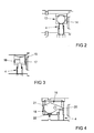
- FIG. 2 shows a check device 13 in a further embodiment of the in FIG. 1 Lock cylinder shown.
- the check-back device 13 here has a check block 14, which is designed as a ball which is opposite the blocking body 4.
- FIG. 3 shows a check device 15 in a further embodiment.
- the check device 15 has two check bodies 16, 17 with different pulse characteristics. The different pulse characteristics are generated by different masses of the check bodies 16, 17.
- FIG. 4 shows a further embodiment of a check device 18 with a pivotally mounted check body 19.
- An arm 20 of the check body 19 abuts against the locking body 4, while a second arm 21 is supported by a spring element 22.
- the second arm 21 also has a greater mass than the first arm 20.
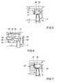
- FIG. 5 shows a check device 23 in another embodiment with two pivotally mounted check bodies 24, 25.
- the check body 24, 25th have different pulse characteristics and are each with an arm 26, 27 the locking body 4 opposite.
- FIG. 6 shows a further embodiment of a check device 28, in which two pivotally mounted check body 29, 30, each with an arm 31, 32 facing the locking body 4.
- the check bodies 29, 30 each have a second arm 33, 34. Bearings 35, 36 and masses of the check bodies 29, 30 are different so that the check bodies 29, 30 have different pulse characteristics. Furthermore, one of the check body 30 is spaced from the locking body 4 located in the closed position, while the other check body 29 rests on the locking body 4.
- FIG. 7 shows a further embodiment of a check device 37 with two pivotally mounted check bodies 38, 39.
- the check body 38, 39 are constructed differently and thus have different pulse characteristics.
- One of the check body 39 rests with one arm 40 on the lock body 4, while the other check body 38 is spaced from the locking body 4 located in the closed position.
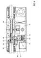
- FIG. 8 shows a lock cylinder with a relative to a housing 41 movable core 42 in another embodiment.
- This lock cylinder differs from that FIG. 1 in that a locking mechanism 43 has an actuator 44 with an electromagnet, which holds a locking bolt 45 having an armature 46 having locking body 47 in the open position of the lock cylinder. In the illustrated closed position of the lock cylinder, the movement of the locking body 47 is released by the actuator 44.
- a coil spring 48 pushes the locking body 47 in a position in which the locking bolt 45 produces a positive connection between the housing 41 and core 42.
- a check-49 is arranged in the housing 41.
- the check device 49 has a pivotally mounted check body 50 which rests with an arm 51 on the locking body 47 and presses it in the illustrated closed position.
- a second arm 52 of the check body 50 generates by gravity the required direction of force of the first arm 51 on the locking body 47.
- check devices 10, 13, 15, 18, 23, 28, 37 can be designed in kinematic reversal or provided with rockers in the in FIG. 8 Lock cylinder shown are used.
Landscapes
- Physics & Mathematics (AREA)
- Electromagnetism (AREA)
- Lock And Its Accessories (AREA)
- Casings For Electric Apparatus (AREA)
Abstract
Description
- Die Erfindung betrifft einen Schließzylinder mit einem in einem Gehäuse bewegbaren Kern, mit einem elektronischen Sperrmechanismus, mit einem von dem Sperrmechanismus ansteuerbaren Aktor zur Verstellung eines zwischen einer die Bewegung des Kerns gegenüber dem Gehäuse wahlweise blockierenden Schließstellung oder freigebenden Offenstellung beweglichen Sperrkörpers.
- Ein solcher Schließzylinder ist beispielsweise aus der
EP 1 148 189 A1 bekannt. Bei diesem Schließzylinder hat der Sperrmechanismus einen Elektromagneten als Aktor, welcher den einen Sperrriegel mit einem Anker aufweisenden Sperrkörper in der Offenstellung hält oder dessen Bewegung in die Schließstellung freigibt. Der Sperrkörper ist von außerhalb des Schließzylinders nicht unmittelbar zugänglich. - Aus der
EP 1 380 714 A2 ist ein Schließzylinder bekannt geworden, bei dem der Aktor ein piezoelektrisches Element hat, welcher den im Gehäuse verschieblichen, einen Sperrriegel aufweisenden Sperrkörper in der Offenstellung vollständig im Gehäuse hält. In Schließstellung ist die Bewegung des Sperrkörpers freigegeben. - Weiterhin ist aus der Praxis ein Schließzylinder bekannt geworden, bei dem der Sperrkörper einen im Gehäuse geführten Gehäusestift und einen im Kern geführten Kernstift hat. Ragt der Kernstift in die Trennebene zwischen Gehäuse und Kern hinein, ist die Bewegung des Kerns blockiert und der Schließzylinder befindet sich in geschlossener Stellung. In dieser Schließstellung wird der Gehäusestift von dem Aktor gehalten, während die Bewegung des Kernstifts freigegeben ist.
- Wenn man in die bekannten Schließzylinder Vibrationen oder Erschütterungen einleitet, besteht die Möglichkeit, dass der Sperrkörper in eine Schwingung versetzt und dabei in die Offenstellung bewegt wird.
- Der Erfindung liegt das Problem zugrunde, einen Schließzylinder der eingangs genannten Art so weiter zu bilden, dass eine Bewegung des Sperrkörpers in die Offenstellung bei einer Einleitung von Vibrationen zuverlässig verhindert wird.
- Dieses Problem wird erfindungsgemäß dadurch gelöst, dass der Sperrkörper mit einer beweglichen Rückschlageinrichtung in Verbindung steht und dass der Sperrkörper bei einer Bewegung der Rückschlageinrichtung in die die Bewegung des Kerns blockierende Stellung bewegbar ist.
- Durch diese Gestaltung führt die Einleitung von Vibrationen in den erfindungsgemäßen Schließzylinder zu einer gleichzeitigen Einleitung von Kräften in den Sperrkörper sowie in die Rückschlageinrichtung. Der Sperrkörper wird dabei jedoch nicht in die Offenstellung bewegt, weil die Belastung durch die Rückschlageinrichtung in die Schließstellung wirkt. Damit wird verhindert, dass der Sperrkörper bei der Einleitung von Vibrationen in die die Bewegung des Kerns freigebende Offenstellung bewegt wird.
- Die Rückschlageinrichtung könnte beispielsweise innerhalb eines Hohlraums des Sperrkörpers angeordnet sein. Die Rückschlageinrichtung gestaltet sich gemäß einer anderen vorteilhaften Weiterbildung der Erfindung konstruktiv besonders einfach, wenn die Rückschlageinrichtung zumindest einen gegenüber dem Sperrkörper beweglichen Rückschlagkörper hat.
- Hohe, auf den Sperrkörper einwirkende Rückstellkräfte lassen sich gemäß einer anderen vorteilhaften Weiterbildung der Erfindung auch bei einem niedrigen Bauraum erreichen, wenn der Rückschlagkörper einen schwenkbaren Arm hat und wenn der Arm in den Bewegungsbereich des Sperrkörpers hineinragt.
- Die Einleitung einer Resonanzfrequenz, bei der die Rückschlageinrichtung von dem Sperrkörper getrennt ist, lässt sich gemäß einer anderen vorteilhaften Weiterbildung der Erfindung einfach vermeiden, wenn die Rückschlageinrichtung zumindest zwei jeweils mit dem Sperrkörper verbundene Rückschlagkörper hat und wenn die Rückschlagkörper unterschiedliche Impulseigenschaften aufweisen. Die unterschiedlichen Impulseigenschaften können beispielsweise unterschiedliche Massen, Hebelarme oder Wirkrichtungen der Rückschlagkörper sein.
- Fehlfunktionen durch den Rückschlagkörper lassen sich gemäß einer anderen vorteilhaften Weiterbildung der Erfindung einfach vermeiden, wenn der Rückschlagkörper bei in Schließstellung befindlichem Sperrkörper von dem Sperrkörper beabstandet ist. In den in Schließstellung befindlichen Sperrkörper werden über den Rückschlagkörper keine Kräfte eingeleitet. In Offenstellung kann der Rückschlagkörper an dem Sperrkörper anliegen, um bei der Einleitung von Vibrationen die Bewegung des Sperrkörpers in Schließstellung sicher zu stellen.
- Häufig hat der Sperrkörper einen in dem Kern geführten Kernstift und einen in dem Gehäuse geführten Gehäusestift. In Offenstellung des Sperrkörpers verläuft eine Trennebene zwischen Kernstift und Gehäusestift zwischen Kern und Gehäuse, während in Schließstellung der Kernstift den Kern mit dem Gehäuse formschlüssig verbindet. Bei solchen Schließzylindern gestaltet sich die Anordnung des Rückschlagkörpers gemäß einer anderen vorteilhaften Weiterbildung der Erfindung besonders einfach, wenn der Rückschlagkörper in dem Kern geführt ist und einem in dem Kern geführten Kernstift des Sperrkörpers gegenüber steht.
- Häufig hat der Sperrkörper einen in Schließstellung von dem Gehäuse in den Kern hineinragenden Sperrriegel. In Offenstellung wird der Sperrriegel von dem Sperrmechanismus vollständig im Gehäuse gehalten. Bei solchen Schließzylindern gestaltet sich die Anordnung des Rückschlagkörpers gemäß einer anderen vorteilhaften Weiterbildung der Erfindung besonders einfach, wenn der Rückschlagkörper in dem Gehäuse geführt ist und einem in Schließstellung von dem Gehäuse in den Kern hineinragenden Sperrriegel des Sperrkörpers gegenüber steht.
- Der erfindungsgemäße Schließzylinder weist eine besonders geringe Anzahl an Bauteilen auf, wenn die Rückschlageinrichtung mittels der Schwerkraft gegen den Sperrkörper bewegbar ist.
- Die Wirkung der Rückschlageinrichtung lässt sich unabhängig von der Einbaulage des erfindungsgemäßen Schließzylinders sicherstellen, wenn die Rückschlageinrichtung mittels eines Federelementes gegen den Sperrkörper vorgespannt ist. Selbstverständlich können in einer Einbaulage auch die Schwerkraft und das Federelement parallel auf die Rückschlageinrichtung einwirken.
- Die Erfindung lässt zahlreiche Ausführungsformen zu. Zur weiteren Verdeutlichung ihres Grundprinzips sind mehrere davon in der Zeichnung dargestellt und werden nachfolgend beschrieben. Diese zeigt in
- Fig. 1
- eine Schnittdarstellung durch einen erfindungsgemäßen Schließzylinder,
- Fig. 2 bis 7
- verschiedene Ausführungsformen einer Rückschlageinrichtung vor einem Sperrkörper des Schließzylinders aus
Figur 1 , - Fig. 8
- eine weitere Ausführungsform des erfindungsgemäßen Schließzylinders im Längsschnitt.
-
Figur 1 zeigt einen Schließzylinder mit einem in einem Gehäuse 1 drehbaren Kern 2 und mit einem elektromagnetisch ansteuerbaren Sperrmechanismus 3. Der Sperrmechanismus 3 hat einen Sperrkörper 4 zur wahlweisen Blockierung oder Freigabe der Bewegung des Kerns 2. Hierzu hat der Sperrkörper 4 einen im Gehäuse 1 angeordneten und von einem Aktor 5 bewegbaren Gehäusestift 6 und einen im Kern 2 geführten Kernstift 7. Der Kernstift 7 ragt in die Trennebene zwischen Gehäuse 1 und Kern 2 hinein. Damit befindet sich der Schließzylinder in einer Schließstellung, in der die Bewegung des Kerns 2 gegenüber dem Gehäuse 1 blockiert ist. In einer nicht dargestellten Offenstellung des Schließzylinders befindet sich die Trennebene zwischen Kernstift 7 und Gehäusestift 6 in der Trennebene zwischen Gehäuse 1 und Kern 2, so dass die Bewegung des Kerns 2 gegenüber dem Gehäuse 1 freigegeben ist. Der Kernstift 7 ist frei beweglich in einer Bohrung 8 des Kerns 2 geführt und mittels einer Wendelfeder 9 gegen den Gehäusestift 6 vorgespannt. - Oberhalb des Kernstiftes 7 ist in dem Kern 2 eine Rückschlageinrichtung 10 angeordnet. Die Rückschlageinrichtung 10 hat einen schwenkbar gelagerten Rückschlagkörper 11, welcher mit einem Arm 12 an dem freien Ende des Kernstiftes 7 des Sperrkörpers 4 anliegt. Wenn sich bei der Einleitung von Vibrationen in den Schließzylinder der Kernstift 7 des Sperrkörpers 4 in die Offenstellung bewegt, führen die Vibrationen auch dazu, dass sich die Rückschlageinrichtung 10 über den Rückschlagkörper 11 und den Kernstift 7 des Sperrkörpers 4 in die dargestellte Schließstellung zurückbewegt.
-
Figur 2 zeigt eine Rückschlageinrichtung 13 in einer weiteren Ausfühungsform für den inFigur 1 dargestellten Schließzylinder. Die Rückschlageinrichtung 13 hat hier einen als dem Sperrkörper 4 gegenüberstehende Kugel ausgebildeten Rückschlagkörper 14. -
Figur 3 zeigt eine Rückschlageinrichtung 15 in einer weiteren Ausfühungsform. Hierbei hat die Rückschlageinrichtung 15 zwei Rückschlagkörper 16, 17 mit unterschiedlichen Impulseigenschaften. Die unterschiedlichen Impulseigenschaften werden von unterschiedlichen Massen der Rückschlagkörper 16, 17 erzeugt. -
Figur 4 zeigt eine weitere Ausführungsform einer Rückschlageinrichtung 18 mit einem schwenkbar gelagerten Rückschlagkörper 19. Ein Arm 20 des Rückschlagkörpers 19 liegt an dem Sperrkörper 4 an, während ein zweiter Arm 21 von einem Federelement 22 abgestützt ist. Der zweite Arm 21 weist zudem eine größere Masse auf als der erste Arm 20. -
Figur 5 zeigt eine Rückschlageinrichtung 23 in einer weiteren Ausführungsform mit zwei schwenkbar gelagerten Rückschlagkörpern 24, 25. Die Rückschlagkörper 24, 25 weisen unterschiedliche Impulseigenschaften auf und stehen mit jeweils einem Arm 26, 27 dem Sperrkörper 4 gegenüber. -
Figur 6 zeigt eine weitere Ausführungsform einer Rückschlageinrichtung 28, bei der zwei schwenkbar gelagerte Rückschlagkörper 29, 30 mit jeweils einem Arm 31, 32 dem Sperrkörper 4 gegenüberstehen. Die Rückschlagkörper 29, 30 haben jeweils einen zweiten Arm 33, 34. Lagerungen 35, 36 und Massen der Rückschlagkörper 29, 30 sind unterschiedlich, so dass die Rückschlagkörper 29, 30 unterschiedliche Impulseigenschaften haben. Weiterhin ist einer der Rückschlagkörper 30 von dem in Schließstellung befindlichen Sperrkörper 4 beabstandet, während der andere Rückschlagkörper 29 auf dem Sperrkörper 4 aufliegt. -
Figur 7 zeigt eine weitere Ausführungsform einer Rückschlageinrichtung 37 mit zwei schwenkbar gelagerten Rückschlagkörpern 38, 39. Die Rückschlagkörper 38, 39 sind unterschiedlich aufgebaut und haben damit unterschiedliche Impulseigenschaften. Einer der Rückschlagkörper 39 liegt mit einem Arm 40 an dem Sperrkörper 4 an, während der andere Rückschlagkörper 38 von dem in Schließstellung befindlichen Sperrkörper 4 beabstandet ist. - Die Wirkung der in den
Figuren 2 bis 7 dargestellten Rückschlageinrichtungen 13, 15, 18, 23, 28, 37 auf den jeweiligen Sperrkörper 4 entspricht der inFigur 1 beschriebenen Rückschlageinrichtung 10. Der Sperrkörper 4 und die übrigen Bauteile des Schließzylinders sind wie inFigur 1 beschrieben aufgebaut. -
Figur 8 zeigt einen Schließzylinder mit einem gegenüber einem Gehäuse 41 beweglichen Kern 42 in einer weiteren Ausführungsform. Dieser Schließzylinder unterscheidet sich von dem ausFigur 1 dadurch, dass ein Sperrmechanismus 43 einen Aktor 44 mit einem Elektromagneten hat, welcher einen einen Sperrriegel 45 mit einem Anker 46 aufweisenden Sperrkörper 47 in Offenstellung des Schließzylinders hält. In der dargestellten Schließstellung des Schließzylinders ist die Bewegung des Sperrkörpers 47 von dem Aktor 44 freigegeben. Eine Wendelfeder 48 drückt den Sperrkörper 47 in eine Stellung, in der der Sperrriegel 45 einen Formschluss zwischen Gehäuse 41 und Kern 42 erzeugt. - In dem Gehäuse 41 ist eine Rückschlageinrichtung 49 angeordnet. Die Rückschlageinrichtung 49 hat einen schwenkbar gelagerten Rückschlagkörper 50, welcher mit einem Arm 51 an dem Sperrkörper 47 anliegt und ihn in die dargestellte Schließstellung drückt. Ein zweiter Arm 52 des Rückschlagkörpers 50 erzeugt über die Schwerkraft die erforderliche Kraftrichtung des ersten Arms 51 auf den Sperrkörper 47. Bei der Einleitung von Vibrationen in den Schließzylinder drückt die Rückschlageinrichtung 49 den Sperrkörper 47 in die Schließstellung des Schließzylinders.
- Die in den
Figuren 1 bis 7 dargestellten Rückschlageinrichtungen 10, 13, 15, 18, 23, 28, 37 können in kinematischer Umkehr gestaltet oder mit Wippen versehen bei dem inFigur 8 dargestellten Schließzylinder eingesetzt werden.
Claims (9)
- Schließzylinder mit einem in einem Gehäuse (1, 41) bewegbaren Kern (2, 42), mit einem elektronischen Sperrmechanismus (3, 43), mit einem von dem Sperrmechanismus (3, 43) ansteuerbaren Aktor (5, 44) zur Verstellung eines zwischen einer die Bewegung des Kerns (2, 42) gegenüber dem Gehäuse (1, 41) wahlweise blockierenden Schließstellung oder freigebenden Offenstellung beweglichen Sperrkörpers (4, 47), dadurch gekennzeichnet, dass der Sperrkörper (4, 47) an einer beweglichen Rückschlageinrichtung (10, 13, 15, 18, 23, 28, 37, 49) anliegt und dass der Sperrkörper (4, 47) bei einer Bewegung der Rückschlageinrichtung (10, 13, 15, 18, 23, 28, 37, 49) in die die Bewegung des Kerns (2, 42) blockierende Stellung bewegbar ist.
- Schließzylinder nach Anspruch 1, dadurch gekennzeichnet, dass die Rückschlageinrichtung (10, 13, 15, 18, 23, 28, 37, 49) zumindest einen gegenüber dem Sperrkörper (4, 47) beweglichen Rückschlagkörper (11, 14, 16, 17, 19, 24, 25, 29, 30, 38, 39, 50) hat.
- Schließzylinder nach Anspruch 2, dadurch gekennzeichnet, dass der Rückschlagkörper (11, 18, 24, 25, 29, 30, 39, 50) einen schwenkbaren Arm (12, 20, 26, 27, 31, 32, 40, 51) hat und dass der Arm (12, 20, 26, 27, 31, 32, 40, 51) in den Bewegungsbereich des Sperrkörpers (4, 47) hineinragt.
- Schließzylinder nach Anspruch 2 oder 3, dadurch gekennzeichnet, dass die Rückschlageinrichtung (15, 23, 28, 37) zumindest zwei jeweils mit dem Sperrkörper (4) verbundene Rückschlagkörper (16, 17, 24, 25, 29, 30, 38, 39) hat und dass die Rückschlagkörper (16, 17, 24, 25, 29, 30, 38, 39) unterschiedliche Impulseigenschaften aufweisen.
- Schließzylinder nach einem der Ansprüche 2 bis 4, dadurch gekennzeichnet, dass der Rückschlagkörper (30, 38) bei in Schließstellung befindlichem Sperrkörper (4) von dem Sperrkörper (4) beabstandet ist.
- Schließzylinder nach einem der Ansprüche 2 bis 5, dadurch gekennzeichnet, dass der Rückschlagkörper (11, 14, 16, 17, 19, 24, 25, 29, 30, 38, 39) in dem Kern (2) geführt ist und einem in dem Kern (2) geführten Kernstift (7) des Sperrkörpers (4) gegenüber steht.
- Schließzylinder nach einem der Ansprüche 2 bis 5, dadurch gekennzeichnet, dass der Rückschlagkörper (50) in dem Gehäuse (41) geführt ist und einem in Schließstellung von dem Gehäuse (41) in den Kern (42) hineinragenden Sperrriegel (45) des Sperrkörpers (47) gegenüber steht.
- Schließzylinder nach einem der vorhergehenden Ansprüche, dadurch gekennzeichnet, dass die Rückschlageinrichtung (10, 13, 15, 23, 28, 37, 49) mittels des Impulses gegen den Sperrkörper (4, 47) bewegbar ist.
- Schließzylinder nach einem der vorhergehenden Ansprüche, dadurch gekennzeichnet, dass die Rückschlageinrichtung (18) mittels eines Federelementes (22) gegen den Sperrkörper (4) vorgespannt ist.
Priority Applications (1)
| Application Number | Priority Date | Filing Date | Title |
|---|---|---|---|
| PL11183995T PL2441906T3 (pl) | 2010-10-15 | 2011-10-05 | Cylinder zamykający |
Applications Claiming Priority (1)
| Application Number | Priority Date | Filing Date | Title |
|---|---|---|---|
| DE102010042486A DE102010042486A1 (de) | 2010-10-15 | 2010-10-15 | Schließzylinder |
Publications (3)
| Publication Number | Publication Date |
|---|---|
| EP2441906A2 true EP2441906A2 (de) | 2012-04-18 |
| EP2441906A3 EP2441906A3 (de) | 2015-04-22 |
| EP2441906B1 EP2441906B1 (de) | 2019-04-24 |
Family
ID=44719727
Family Applications (1)
| Application Number | Title | Priority Date | Filing Date |
|---|---|---|---|
| EP11183995.7A Not-in-force EP2441906B1 (de) | 2010-10-15 | 2011-10-05 | Schließzylinder |
Country Status (4)
| Country | Link |
|---|---|
| EP (1) | EP2441906B1 (de) |
| DE (1) | DE102010042486A1 (de) |
| ES (1) | ES2729774T3 (de) |
| PL (1) | PL2441906T3 (de) |
Cited By (5)
| Publication number | Priority date | Publication date | Assignee | Title |
|---|---|---|---|---|
| CN104074410A (zh) * | 2014-06-26 | 2014-10-01 | 刘勇 | 智能锁芯 |
| DE102017206927A1 (de) | 2017-04-25 | 2018-10-25 | Aug. Winkhaus Gmbh & Co. Kg | Schließanlage |
| CN111197431A (zh) * | 2019-12-30 | 2020-05-26 | 厦门美科物联科技有限公司 | 一种新型电子锁结构 |
| WO2021066718A1 (en) * | 2019-10-03 | 2021-04-08 | Swedlock Ab | Electromechanical lock assembly with annular element, blocking and retaining devices |
| WO2022211689A1 (en) * | 2021-04-01 | 2022-10-06 | Swedlock Ab | Electromechanical lock assembly |
Citations (2)
| Publication number | Priority date | Publication date | Assignee | Title |
|---|---|---|---|---|
| EP1148189A1 (de) | 2000-04-22 | 2001-10-24 | Aug. Winkhaus GmbH & Co. KG | Elektromagnetisch aktivierbarer Sperrmechanismus |
| EP1380714A2 (de) | 2002-07-10 | 2004-01-14 | Aug. Winkhaus GmbH & Co. KG | Sperrmechanismus, insbesondere für einen Schliesszylinder |
Family Cites Families (3)
| Publication number | Priority date | Publication date | Assignee | Title |
|---|---|---|---|---|
| SE505493C2 (sv) * | 1992-03-26 | 1997-09-08 | Assa Ab | Cylinderlås |
| FI112691B (fi) * | 2002-12-05 | 2003-12-31 | Abloy Oy | Järjestely sähkömekaanisessa sylinterilukossa |
| DE102005054643B3 (de) * | 2005-11-10 | 2007-02-15 | Assa Abloy Sicherheitstechnik Gmbh | Schließzylinder |
-
2010
- 2010-10-15 DE DE102010042486A patent/DE102010042486A1/de not_active Withdrawn
-
2011
- 2011-10-05 ES ES11183995T patent/ES2729774T3/es active Active
- 2011-10-05 PL PL11183995T patent/PL2441906T3/pl unknown
- 2011-10-05 EP EP11183995.7A patent/EP2441906B1/de not_active Not-in-force
Patent Citations (2)
| Publication number | Priority date | Publication date | Assignee | Title |
|---|---|---|---|---|
| EP1148189A1 (de) | 2000-04-22 | 2001-10-24 | Aug. Winkhaus GmbH & Co. KG | Elektromagnetisch aktivierbarer Sperrmechanismus |
| EP1380714A2 (de) | 2002-07-10 | 2004-01-14 | Aug. Winkhaus GmbH & Co. KG | Sperrmechanismus, insbesondere für einen Schliesszylinder |
Cited By (8)
| Publication number | Priority date | Publication date | Assignee | Title |
|---|---|---|---|---|
| CN104074410A (zh) * | 2014-06-26 | 2014-10-01 | 刘勇 | 智能锁芯 |
| CN104074410B (zh) * | 2014-06-26 | 2016-11-09 | 刘勇 | 智能锁芯 |
| DE102017206927A1 (de) | 2017-04-25 | 2018-10-25 | Aug. Winkhaus Gmbh & Co. Kg | Schließanlage |
| EP3396641A1 (de) | 2017-04-25 | 2018-10-31 | Aug. Winkhaus GmbH & Co. KG | Schliessanlage |
| WO2021066718A1 (en) * | 2019-10-03 | 2021-04-08 | Swedlock Ab | Electromechanical lock assembly with annular element, blocking and retaining devices |
| US12037814B2 (en) | 2019-10-03 | 2024-07-16 | Swedlock Ab | Electromechanical lock assembly with annular element, blocking and retaining devices |
| CN111197431A (zh) * | 2019-12-30 | 2020-05-26 | 厦门美科物联科技有限公司 | 一种新型电子锁结构 |
| WO2022211689A1 (en) * | 2021-04-01 | 2022-10-06 | Swedlock Ab | Electromechanical lock assembly |
Also Published As
| Publication number | Publication date |
|---|---|
| EP2441906B1 (de) | 2019-04-24 |
| EP2441906A3 (de) | 2015-04-22 |
| PL2441906T3 (pl) | 2019-08-30 |
| DE102010042486A1 (de) | 2012-04-19 |
| ES2729774T3 (es) | 2019-11-06 |
Similar Documents
| Publication | Publication Date | Title |
|---|---|---|
| EP0922821B1 (de) | Türöffner | |
| EP2441906B1 (de) | Schließzylinder | |
| WO2020030391A1 (de) | Kupplungsbaugruppe für einen kraftfahrzeugantriebsstrang sowie kraftfahrzeugantriebsstrang | |
| CH715081A2 (de) | Elektromagnetischer Aktuator. | |
| DE102011013255B4 (de) | Entriegelungsvorrichtung | |
| DE102009005322A1 (de) | Elektronische Schließeinheit | |
| EP2287424B1 (de) | Schliesszylinder | |
| EP1516983B1 (de) | Schliesszylinder | |
| EP3243980B1 (de) | Verriegelungssystem | |
| EP3418476B1 (de) | Schliesszylinder mit einem zum schliessen berechtigten schlüssel | |
| DE102012018080A1 (de) | Elektromechanische Zuhaltung mit Überlastschutz | |
| EP1505229B1 (de) | Schliesszylinder | |
| EP1638117B1 (de) | Betätigungsmagnet | |
| DE102017101758A1 (de) | Blockiervorrichtung zum Blockieren eines Türflügels einer Flügeltüranlage und Blockiersystem | |
| EP3315695B1 (de) | Schloss | |
| DE102022208525B4 (de) | Feststelleinrichtung sowie Türantrieb | |
| EP1726751B1 (de) | Schließzylinder | |
| EP4098568B1 (de) | Auslösevorrichtung | |
| DE102010019578A1 (de) | Türöffner | |
| EP3725985B1 (de) | Türöffner | |
| EP1710376B1 (de) | Schließzylinder | |
| EP3093416A1 (de) | Schloss | |
| WO2011131300A1 (de) | Türöffner | |
| DE1447403C (de) | Mechanische Verriegelung fur zwei gegeneinander verschiebbare Bauteile | |
| EP0815776A1 (de) | Vorrichtung zur Auszugssicherung von über- oder nebeneinander angeordneten Bauteilen |
Legal Events
| Date | Code | Title | Description |
|---|---|---|---|
| PUAI | Public reference made under article 153(3) epc to a published international application that has entered the european phase |
Free format text: ORIGINAL CODE: 0009012 |
|
| AK | Designated contracting states |
Kind code of ref document: A2 Designated state(s): AL AT BE BG CH CY CZ DE DK EE ES FI FR GB GR HR HU IE IS IT LI LT LU LV MC MK MT NL NO PL PT RO RS SE SI SK SM TR |
|
| AX | Request for extension of the european patent |
Extension state: BA ME |
|
| PUAL | Search report despatched |
Free format text: ORIGINAL CODE: 0009013 |
|
| AK | Designated contracting states |
Kind code of ref document: A3 Designated state(s): AL AT BE BG CH CY CZ DE DK EE ES FI FR GB GR HR HU IE IS IT LI LT LU LV MC MK MT NL NO PL PT RO RS SE SI SK SM TR |
|
| AX | Request for extension of the european patent |
Extension state: BA ME |
|
| RIC1 | Information provided on ipc code assigned before grant |
Ipc: E05B 9/04 20060101ALI20150313BHEP Ipc: E05B 47/06 20060101AFI20150313BHEP |
|
| 17P | Request for examination filed |
Effective date: 20150903 |
|
| RBV | Designated contracting states (corrected) |
Designated state(s): AL AT BE BG CH CY CZ DE DK EE ES FI FR GB GR HR HU IE IS IT LI LT LU LV MC MK MT NL NO PL PT RO RS SE SI SK SM TR |
|
| STAA | Information on the status of an ep patent application or granted ep patent |
Free format text: STATUS: EXAMINATION IS IN PROGRESS |
|
| 17Q | First examination report despatched |
Effective date: 20170828 |
|
| GRAP | Despatch of communication of intention to grant a patent |
Free format text: ORIGINAL CODE: EPIDOSNIGR1 |
|
| STAA | Information on the status of an ep patent application or granted ep patent |
Free format text: STATUS: GRANT OF PATENT IS INTENDED |
|
| INTG | Intention to grant announced |
Effective date: 20181207 |
|
| GRAS | Grant fee paid |
Free format text: ORIGINAL CODE: EPIDOSNIGR3 |
|
| GRAA | (expected) grant |
Free format text: ORIGINAL CODE: 0009210 |
|
| STAA | Information on the status of an ep patent application or granted ep patent |
Free format text: STATUS: THE PATENT HAS BEEN GRANTED |
|
| AK | Designated contracting states |
Kind code of ref document: B1 Designated state(s): AL AT BE BG CH CY CZ DE DK EE ES FI FR GB GR HR HU IE IS IT LI LT LU LV MC MK MT NL NO PL PT RO RS SE SI SK SM TR |
|
| REG | Reference to a national code |
Ref country code: GB Ref legal event code: FG4D Free format text: NOT ENGLISH |
|
| REG | Reference to a national code |
Ref country code: CH Ref legal event code: EP |
|
| REG | Reference to a national code |
Ref country code: DE Ref legal event code: R096 Ref document number: 502011015620 Country of ref document: DE |
|
| REG | Reference to a national code |
Ref country code: CH Ref legal event code: NV Representative=s name: FELBER UND PARTNER AG, CH Ref country code: AT Ref legal event code: REF Ref document number: 1124348 Country of ref document: AT Kind code of ref document: T Effective date: 20190515 Ref country code: IE Ref legal event code: FG4D Free format text: LANGUAGE OF EP DOCUMENT: GERMAN |
|
| REG | Reference to a national code |
Ref country code: NL Ref legal event code: FP |
|
| REG | Reference to a national code |
Ref country code: LT Ref legal event code: MG4D |
|
| PG25 | Lapsed in a contracting state [announced via postgrant information from national office to epo] |
Ref country code: NO Free format text: LAPSE BECAUSE OF FAILURE TO SUBMIT A TRANSLATION OF THE DESCRIPTION OR TO PAY THE FEE WITHIN THE PRESCRIBED TIME-LIMIT Effective date: 20190724 Ref country code: LT Free format text: LAPSE BECAUSE OF FAILURE TO SUBMIT A TRANSLATION OF THE DESCRIPTION OR TO PAY THE FEE WITHIN THE PRESCRIBED TIME-LIMIT Effective date: 20190424 Ref country code: FI Free format text: LAPSE BECAUSE OF FAILURE TO SUBMIT A TRANSLATION OF THE DESCRIPTION OR TO PAY THE FEE WITHIN THE PRESCRIBED TIME-LIMIT Effective date: 20190424 Ref country code: AL Free format text: LAPSE BECAUSE OF FAILURE TO SUBMIT A TRANSLATION OF THE DESCRIPTION OR TO PAY THE FEE WITHIN THE PRESCRIBED TIME-LIMIT Effective date: 20190424 Ref country code: PT Free format text: LAPSE BECAUSE OF FAILURE TO SUBMIT A TRANSLATION OF THE DESCRIPTION OR TO PAY THE FEE WITHIN THE PRESCRIBED TIME-LIMIT Effective date: 20190824 Ref country code: SE Free format text: LAPSE BECAUSE OF FAILURE TO SUBMIT A TRANSLATION OF THE DESCRIPTION OR TO PAY THE FEE WITHIN THE PRESCRIBED TIME-LIMIT Effective date: 20190424 Ref country code: HR Free format text: LAPSE BECAUSE OF FAILURE TO SUBMIT A TRANSLATION OF THE DESCRIPTION OR TO PAY THE FEE WITHIN THE PRESCRIBED TIME-LIMIT Effective date: 20190424 |
|
| REG | Reference to a national code |
Ref country code: ES Ref legal event code: FG2A Ref document number: 2729774 Country of ref document: ES Kind code of ref document: T3 Effective date: 20191106 |
|
| PG25 | Lapsed in a contracting state [announced via postgrant information from national office to epo] |
Ref country code: GR Free format text: LAPSE BECAUSE OF FAILURE TO SUBMIT A TRANSLATION OF THE DESCRIPTION OR TO PAY THE FEE WITHIN THE PRESCRIBED TIME-LIMIT Effective date: 20190725 Ref country code: LV Free format text: LAPSE BECAUSE OF FAILURE TO SUBMIT A TRANSLATION OF THE DESCRIPTION OR TO PAY THE FEE WITHIN THE PRESCRIBED TIME-LIMIT Effective date: 20190424 Ref country code: BG Free format text: LAPSE BECAUSE OF FAILURE TO SUBMIT A TRANSLATION OF THE DESCRIPTION OR TO PAY THE FEE WITHIN THE PRESCRIBED TIME-LIMIT Effective date: 20190724 Ref country code: RS Free format text: LAPSE BECAUSE OF FAILURE TO SUBMIT A TRANSLATION OF THE DESCRIPTION OR TO PAY THE FEE WITHIN THE PRESCRIBED TIME-LIMIT Effective date: 20190424 |
|
| PGFP | Annual fee paid to national office [announced via postgrant information from national office to epo] |
Ref country code: PL Payment date: 20190910 Year of fee payment: 9 |
|
| PG25 | Lapsed in a contracting state [announced via postgrant information from national office to epo] |
Ref country code: IS Free format text: LAPSE BECAUSE OF FAILURE TO SUBMIT A TRANSLATION OF THE DESCRIPTION OR TO PAY THE FEE WITHIN THE PRESCRIBED TIME-LIMIT Effective date: 20190824 |
|
| REG | Reference to a national code |
Ref country code: DE Ref legal event code: R097 Ref document number: 502011015620 Country of ref document: DE |
|
| PG25 | Lapsed in a contracting state [announced via postgrant information from national office to epo] |
Ref country code: EE Free format text: LAPSE BECAUSE OF FAILURE TO SUBMIT A TRANSLATION OF THE DESCRIPTION OR TO PAY THE FEE WITHIN THE PRESCRIBED TIME-LIMIT Effective date: 20190424 Ref country code: CZ Free format text: LAPSE BECAUSE OF FAILURE TO SUBMIT A TRANSLATION OF THE DESCRIPTION OR TO PAY THE FEE WITHIN THE PRESCRIBED TIME-LIMIT Effective date: 20190424 Ref country code: RO Free format text: LAPSE BECAUSE OF FAILURE TO SUBMIT A TRANSLATION OF THE DESCRIPTION OR TO PAY THE FEE WITHIN THE PRESCRIBED TIME-LIMIT Effective date: 20190424 Ref country code: DK Free format text: LAPSE BECAUSE OF FAILURE TO SUBMIT A TRANSLATION OF THE DESCRIPTION OR TO PAY THE FEE WITHIN THE PRESCRIBED TIME-LIMIT Effective date: 20190424 Ref country code: SK Free format text: LAPSE BECAUSE OF FAILURE TO SUBMIT A TRANSLATION OF THE DESCRIPTION OR TO PAY THE FEE WITHIN THE PRESCRIBED TIME-LIMIT Effective date: 20190424 |
|
| PG25 | Lapsed in a contracting state [announced via postgrant information from national office to epo] |
Ref country code: SM Free format text: LAPSE BECAUSE OF FAILURE TO SUBMIT A TRANSLATION OF THE DESCRIPTION OR TO PAY THE FEE WITHIN THE PRESCRIBED TIME-LIMIT Effective date: 20190424 |
|
| PLBE | No opposition filed within time limit |
Free format text: ORIGINAL CODE: 0009261 |
|
| STAA | Information on the status of an ep patent application or granted ep patent |
Free format text: STATUS: NO OPPOSITION FILED WITHIN TIME LIMIT |
|
| PG25 | Lapsed in a contracting state [announced via postgrant information from national office to epo] |
Ref country code: TR Free format text: LAPSE BECAUSE OF FAILURE TO SUBMIT A TRANSLATION OF THE DESCRIPTION OR TO PAY THE FEE WITHIN THE PRESCRIBED TIME-LIMIT Effective date: 20190424 |
|
| PGFP | Annual fee paid to national office [announced via postgrant information from national office to epo] |
Ref country code: CH Payment date: 20191025 Year of fee payment: 9 |
|
| 26N | No opposition filed |
Effective date: 20200127 |
|
| PG25 | Lapsed in a contracting state [announced via postgrant information from national office to epo] |
Ref country code: SI Free format text: LAPSE BECAUSE OF FAILURE TO SUBMIT A TRANSLATION OF THE DESCRIPTION OR TO PAY THE FEE WITHIN THE PRESCRIBED TIME-LIMIT Effective date: 20190424 Ref country code: MC Free format text: LAPSE BECAUSE OF FAILURE TO SUBMIT A TRANSLATION OF THE DESCRIPTION OR TO PAY THE FEE WITHIN THE PRESCRIBED TIME-LIMIT Effective date: 20190424 |
|
| PG25 | Lapsed in a contracting state [announced via postgrant information from national office to epo] |
Ref country code: LU Free format text: LAPSE BECAUSE OF NON-PAYMENT OF DUE FEES Effective date: 20191005 |
|
| REG | Reference to a national code |
Ref country code: BE Ref legal event code: MM Effective date: 20191031 |
|
| PG25 | Lapsed in a contracting state [announced via postgrant information from national office to epo] |
Ref country code: BE Free format text: LAPSE BECAUSE OF NON-PAYMENT OF DUE FEES Effective date: 20191031 |
|
| PG25 | Lapsed in a contracting state [announced via postgrant information from national office to epo] |
Ref country code: IE Free format text: LAPSE BECAUSE OF NON-PAYMENT OF DUE FEES Effective date: 20191005 |
|
| PGFP | Annual fee paid to national office [announced via postgrant information from national office to epo] |
Ref country code: NL Payment date: 20201027 Year of fee payment: 10 |
|
| PGFP | Annual fee paid to national office [announced via postgrant information from national office to epo] |
Ref country code: AT Payment date: 20201021 Year of fee payment: 10 Ref country code: ES Payment date: 20201117 Year of fee payment: 10 Ref country code: GB Payment date: 20201027 Year of fee payment: 10 Ref country code: FR Payment date: 20201027 Year of fee payment: 10 Ref country code: IT Payment date: 20201022 Year of fee payment: 10 |
|
| PG25 | Lapsed in a contracting state [announced via postgrant information from national office to epo] |
Ref country code: CY Free format text: LAPSE BECAUSE OF FAILURE TO SUBMIT A TRANSLATION OF THE DESCRIPTION OR TO PAY THE FEE WITHIN THE PRESCRIBED TIME-LIMIT Effective date: 20190424 |
|
| REG | Reference to a national code |
Ref country code: CH Ref legal event code: PL |
|
| PG25 | Lapsed in a contracting state [announced via postgrant information from national office to epo] |
Ref country code: HU Free format text: LAPSE BECAUSE OF FAILURE TO SUBMIT A TRANSLATION OF THE DESCRIPTION OR TO PAY THE FEE WITHIN THE PRESCRIBED TIME-LIMIT; INVALID AB INITIO Effective date: 20111005 Ref country code: MT Free format text: LAPSE BECAUSE OF FAILURE TO SUBMIT A TRANSLATION OF THE DESCRIPTION OR TO PAY THE FEE WITHIN THE PRESCRIBED TIME-LIMIT Effective date: 20190424 |
|
| PG25 | Lapsed in a contracting state [announced via postgrant information from national office to epo] |
Ref country code: CH Free format text: LAPSE BECAUSE OF NON-PAYMENT OF DUE FEES Effective date: 20201031 Ref country code: LI Free format text: LAPSE BECAUSE OF NON-PAYMENT OF DUE FEES Effective date: 20201031 |
|
| REG | Reference to a national code |
Ref country code: NL Ref legal event code: MM Effective date: 20211101 |
|
| REG | Reference to a national code |
Ref country code: AT Ref legal event code: MM01 Ref document number: 1124348 Country of ref document: AT Kind code of ref document: T Effective date: 20211005 |
|
| GBPC | Gb: european patent ceased through non-payment of renewal fee |
Effective date: 20211005 |
|
| PG25 | Lapsed in a contracting state [announced via postgrant information from national office to epo] |
Ref country code: MK Free format text: LAPSE BECAUSE OF FAILURE TO SUBMIT A TRANSLATION OF THE DESCRIPTION OR TO PAY THE FEE WITHIN THE PRESCRIBED TIME-LIMIT Effective date: 20190424 |
|
| PG25 | Lapsed in a contracting state [announced via postgrant information from national office to epo] |
Ref country code: NL Free format text: LAPSE BECAUSE OF NON-PAYMENT OF DUE FEES Effective date: 20211101 Ref country code: GB Free format text: LAPSE BECAUSE OF NON-PAYMENT OF DUE FEES Effective date: 20211005 |
|
| PG25 | Lapsed in a contracting state [announced via postgrant information from national office to epo] |
Ref country code: AT Free format text: LAPSE BECAUSE OF NON-PAYMENT OF DUE FEES Effective date: 20211005 |
|
| PG25 | Lapsed in a contracting state [announced via postgrant information from national office to epo] |
Ref country code: FR Free format text: LAPSE BECAUSE OF NON-PAYMENT OF DUE FEES Effective date: 20211031 |
|
| PG25 | Lapsed in a contracting state [announced via postgrant information from national office to epo] |
Ref country code: IT Free format text: LAPSE BECAUSE OF NON-PAYMENT OF DUE FEES Effective date: 20211005 |
|
| PG25 | Lapsed in a contracting state [announced via postgrant information from national office to epo] |
Ref country code: PL Free format text: LAPSE BECAUSE OF NON-PAYMENT OF DUE FEES Effective date: 20201005 |
|
| PGFP | Annual fee paid to national office [announced via postgrant information from national office to epo] |
Ref country code: DE Payment date: 20221020 Year of fee payment: 12 |
|
| REG | Reference to a national code |
Ref country code: ES Ref legal event code: FD2A Effective date: 20230213 |
|
| PG25 | Lapsed in a contracting state [announced via postgrant information from national office to epo] |
Ref country code: ES Free format text: LAPSE BECAUSE OF NON-PAYMENT OF DUE FEES Effective date: 20211006 |
|
| P01 | Opt-out of the competence of the unified patent court (upc) registered |
Effective date: 20230515 |
|
| REG | Reference to a national code |
Ref country code: DE Ref legal event code: R119 Ref document number: 502011015620 Country of ref document: DE |
|
| PG25 | Lapsed in a contracting state [announced via postgrant information from national office to epo] |
Ref country code: DE Free format text: LAPSE BECAUSE OF NON-PAYMENT OF DUE FEES Effective date: 20240501 |