EP2441669A2 - Aktive Strömungsssteuerung auf einer Heckflosse mit einem Seitenruder - Google Patents
Aktive Strömungsssteuerung auf einer Heckflosse mit einem Seitenruder Download PDFInfo
- Publication number
- EP2441669A2 EP2441669A2 EP20110183674 EP11183674A EP2441669A2 EP 2441669 A2 EP2441669 A2 EP 2441669A2 EP 20110183674 EP20110183674 EP 20110183674 EP 11183674 A EP11183674 A EP 11183674A EP 2441669 A2 EP2441669 A2 EP 2441669A2
- Authority
- EP
- European Patent Office
- Prior art keywords
- flow control
- vertical
- active flow
- actuators
- control
- Prior art date
- Legal status (The legal status is an assumption and is not a legal conclusion. Google has not performed a legal analysis and makes no representation as to the accuracy of the status listed.)
- Granted
Links
Images



Classifications
-
- B—PERFORMING OPERATIONS; TRANSPORTING
- B64—AIRCRAFT; AVIATION; COSMONAUTICS
- B64C—AEROPLANES; HELICOPTERS
- B64C5/00—Stabilising surfaces
- B64C5/06—Fins
-
- B—PERFORMING OPERATIONS; TRANSPORTING
- B64—AIRCRAFT; AVIATION; COSMONAUTICS
- B64C—AEROPLANES; HELICOPTERS
- B64C21/00—Influencing air flow over aircraft surfaces by affecting boundary layer flow
-
- B—PERFORMING OPERATIONS; TRANSPORTING
- B64—AIRCRAFT; AVIATION; COSMONAUTICS
- B64C—AEROPLANES; HELICOPTERS
- B64C23/00—Influencing air flow over aircraft surfaces, not otherwise provided for
- B64C23/005—Influencing air flow over aircraft surfaces, not otherwise provided for by other means not covered by groups B64C23/02 - B64C23/08, e.g. by electric charges, magnetic panels, piezoelectric elements, static charges or ultrasounds
-
- B—PERFORMING OPERATIONS; TRANSPORTING
- B64—AIRCRAFT; AVIATION; COSMONAUTICS
- B64C—AEROPLANES; HELICOPTERS
- B64C23/00—Influencing air flow over aircraft surfaces, not otherwise provided for
- B64C23/06—Influencing air flow over aircraft surfaces, not otherwise provided for by generating vortices
-
- B—PERFORMING OPERATIONS; TRANSPORTING
- B64—AIRCRAFT; AVIATION; COSMONAUTICS
- B64C—AEROPLANES; HELICOPTERS
- B64C2230/00—Boundary layer controls
- B64C2230/04—Boundary layer controls by actively generating fluid flow
-
- B—PERFORMING OPERATIONS; TRANSPORTING
- B64—AIRCRAFT; AVIATION; COSMONAUTICS
- B64C—AEROPLANES; HELICOPTERS
- B64C2230/00—Boundary layer controls
- B64C2230/16—Boundary layer controls by blowing other fluids over the surface than air, e.g. He, H, O2 or exhaust gases
-
- Y—GENERAL TAGGING OF NEW TECHNOLOGICAL DEVELOPMENTS; GENERAL TAGGING OF CROSS-SECTIONAL TECHNOLOGIES SPANNING OVER SEVERAL SECTIONS OF THE IPC; TECHNICAL SUBJECTS COVERED BY FORMER USPC CROSS-REFERENCE ART COLLECTIONS [XRACs] AND DIGESTS
- Y02—TECHNOLOGIES OR APPLICATIONS FOR MITIGATION OR ADAPTATION AGAINST CLIMATE CHANGE
- Y02T—CLIMATE CHANGE MITIGATION TECHNOLOGIES RELATED TO TRANSPORTATION
- Y02T50/00—Aeronautics or air transport
- Y02T50/10—Drag reduction
-
- Y—GENERAL TAGGING OF NEW TECHNOLOGICAL DEVELOPMENTS; GENERAL TAGGING OF CROSS-SECTIONAL TECHNOLOGIES SPANNING OVER SEVERAL SECTIONS OF THE IPC; TECHNICAL SUBJECTS COVERED BY FORMER USPC CROSS-REFERENCE ART COLLECTIONS [XRACs] AND DIGESTS
- Y10—TECHNICAL SUBJECTS COVERED BY FORMER USPC
- Y10T—TECHNICAL SUBJECTS COVERED BY FORMER US CLASSIFICATION
- Y10T137/00—Fluid handling
- Y10T137/0318—Processes
Definitions
- the vertical tail of an aircraft may include a fixed vertical stabilizer and a moveable rudder that is hinged at the trailing edge of the vertical stabilizer.
- the vertical tail provides a force that allows a pilot to properly align and maintain control of the aircraft.
- the pilot increases the force created by the vertical tail to provide a desired yawing moment on the aircraft.
- the size of the vertical tail is determined according to the designed flight envelope in which the aircraft will operate and the necessary forces to sustain controlled flight within the boundaries of that envelope.
- the force required to be produced by the vertical tail to maintain control of the aircraft may be at a maximum.
- this force is calculated and the vertical tail is sized accordingly to ensure the capability of producing this force in the event that those emergency situations or flight operations at the boundaries of the desired flight envelope arise.
- Systems and methods described herein provide for an active flow control system for controlling an airflow over a vertical control surface of an aircraft. Utilizing the concepts described herein, the forces created by the vertical tail of an aircraft can be selectively enhanced and allow the size and corresponding weight of the vertical tail to be significantly reduced as compared to a conventional aircraft tail while maintaining yaw control for the aircraft throughout the designed flight envelope.
- an active flow control system includes a vertical control surface, one or more active flow control actuators, and an actuator control system.
- the active flow control actuators are mounted on or within the vertical control surface and when activated, alter one or more characteristics of the airflow over the surface.
- the actuator control system detects a flow control event for which airflow actuation is desirable. In response to detecting the event, the actuator control system activates the flow control actuators to control the airflow.
- a method of controlling airflow over a vertical control surface of an aircraft includes detecting a flow control event associated with the surface. In response to detecting the flow control event, one or more active flow control actuators are activated. The active flow control actuators interact with the ambient airflow, altering the airflow as it passes over the vertical control surface.
- the active flow control actuators are mounted within the vertical control surface within a number of zones. When activated, the active flow control actuators alter a flow characteristic of the airflow.
- the actuator control system is linked to the actuators and includes a number of sensors and a controller.
- the sensors collect data associated with a flow control event.
- the controller utilizes the collected data to detect the flow control event. After detecting the event, the controller identifies a subset of the total number of actuators for activation. The subset corresponds to a zone in which activation of the member actuators is effective in controlling the airflow in response to the flow control event.
- the controller activates the actuators within the identified zone or subset of actuators.
- An active flow control system for controlling an airflow over a vertical control surface of an aircraft, comprising: the vertical control surface; at least one active flow control actuator engaging the vertical control surface and operative to alter a flow characteristic of the airflow over the vertical control surface when activated; and an actuator control system communicatively linked to the at least one active flow control actuator, the actuator control system operative to detect a flow control event, and in response to detecting the flow control event, to activate the at least one active flow control actuator.
- the at least one active flow control actuator comprises a synthetic jet actuator, a sweep jet actuator, a flipperon, or an active vortex generator.
- the at least one active flow control actuator comprises a plurality of active flow control actuators positioned within a plurality of zones of the vertical control surface, and wherein the actuator control system is further operative to activate the plurality of active flow control actuators according to zone membership.
- the system wherein the plurality of zones are sequentially vertically arranged from a root of the vertical control surface abutting an aircraft fuselage to a tip of the vertical control surface opposite the root.
- the plurality of zones comprises any subset of active flow control actuators of the plurality of active flow control actuators
- the actuator control system is further operative to identify the subset of active flow control actuators for activation according to the flow control event, and wherein activating the at least one active flow control actuator comprises activating the subset of active flow control actuators.
- the flow control event comprises a flow separation indicator within a zone of the plurality of zones
- the actuator control system being operative to detect the flow control event comprises the actuator control system being operative to detect the flow separation indicator within the zone
- the actuator control system being operative to activate the at least one active flow control device comprises the actuator control system being operative to activate one or more active flow control devices within the zone.
- the vertical control surface comprises a vertical stabilizer and a rudder
- the flow control event comprises a flow separation indicator
- the actuator control system comprises at least one pressure sensor positioned on the vertical stabilizer or the rudder such that the at least one pressure sensor is operative to detect the flow separation indicator corresponding to the vertical stabilizer or rudder.
- the vertical control surface comprises a vertical stabilizer and a rudder
- the actuator control system comprises at least one rudder deflection sensor operative to detect a rudder deflection angle
- the flow control event comprises at least a threshold rudder deflection angle
- the system wherein the flow control event comprises one or more control inputs to a flight control system of the aircraft.
- the vertical control surface comprises a vertical stabilizer and a rudder
- the plurality of active flow control actuators are positioned substantially linearly on or within the vertical stabilizer proximate to the leading edge of the vertical stabilizer.
- the vertical control surface comprises a vertical stabilizer and a rudder
- the plurality of active flow control actuators are positioned substantially linearly on or within the vertical stabilizer proximate to the leading edge of the rudder.
- the vertical control surface comprises a vertical stabilizer and a rudder
- the plurality of active flow control actuators are positioned substantially linearly on or within the rudder proximate to the leading edge of the rudder.
- the vertical control surface comprises a vertical stabilizer and a rudder
- the plurality of active flow control actuators comprises a first plurality of active flow control actuators and a second plurality of active flow control actuators
- the first plurality of active flow control actuators are positioned substantially linearly on or within the vertical stabilizer proximate to the leading edge of the vertical stabilizer and the second plurality of active flow control actuators are positioned substantially linearly proximate to the leading edge of the rudder.
- a method of controlling an airflow over a vertical control surface of an aircraft comprising: detecting a flow control event associated with the vertical control surface; in response to detecting the flow control event, activating one or more active flow control actuators associated with the vertical control surface such that the airflow over the vertical control surface is altered.
- the one or more active flow control actuators comprise a plurality of active flow control actuators positioned within a plurality of zones of the vertical control surface, and wherein activating the plurality of active flow control actuators comprises activating a subset of the plurality of active flow control actuators corresponding to a zone associated with the flow control event.
- detecting the flow control event comprises detecting a rudder deflection angle greater than a predetermined threshold angle, detecting a pressure gradient associated with the airflow indicative of an impending or current flow separation, detecting a control input to a flight control system of the aircraft, or detecting a flow control flight parameter.
- the method further comprising determining a reduced power input for the one or more active flow control actuators corresponding to the flow control event, wherein activating the plurality of active flow control actuators comprises providing the reduced power input to the one or more active flow control actuators.
- the vertical control surface comprises a vertical stabilizer and a rudder
- detecting the flow control event comprises detecting with a plurality of pressure sensors a pressure gradient associated with the airflow indicative of an impending or current flow separation
- activating the one or more active flow control actuators associated with the vertical control surface comprises activating the one of more active flow control actuators proximate to a leading edge of the rudder.
- An active flow control system for controlling an airflow over a vertical control surface of an aircraft, comprising: the vertical control surface; a plurality of active flow control actuators mounted within the vertical control surface according to a plurality of zones and operative to alter a flow characteristic of the airflow over the vertical control surface when activated; and an actuator control system communicatively linked to the plurality of active flow control actuators, the actuator control system comprising a plurality of sensors operative to collect data associated with a flow control event, and a controller operative to utilize the data to detect the flow control event, to identify a subset of the plurality of active flow control actuators corresponding to a zone for controlling the airflow in response to the flow control event, and to activate the subset of the plurality of active flow control actuators.
- the plurality of sensors comprises a plurality of pressure sensors
- the controller being operative to utilize the data to detect the flow control event comprises the controller being operative to utilize pressure sensor data to detect a pressure gradient associated with the airflow indicative of an impending or current flow separation, and wherein the controller is further operative to identify a power input level associated with the subset of the plurality of active flow control actuators such that activating the subset of the plurality of active flow control actuators comprises providing the identified power input level to each of the active flow control actuators of the subset.
- active flow control actuation techniques are used to selectively enhance the ambient airflow characteristics over the vertical tail surfaces, and consequently increase the forces produced by the surfaces. In doing so, the relative size of the vertical tail surfaces may be substantially reduced, while maintaining the performance capabilities of a conventionally sized, unactuated aircraft vertical tail.
- FIGURES 1A and 1B show a comparison between a conventional aircraft vertical tail 100 and an enhanced flow control tail 120 according to embodiments described herein.
- FIGURE 1A shows an example of the conventional aircraft vertical tail 100.
- the conventional aircraft vertical tail 100 includes a vertical control surface 102 mounted to a rear fuselage portion 104.
- the vertical control surface 102 includes a vertical stabilizer 106 and a rudder 108 that is attached to the vertical stabilizer 106 via a hinge and rotatable around the hinge to provide the appropriate yawing force according to a corresponding deflection angle.
- the size of the conventional vertical control surface 102 is illustrated with the dimensional arrows corresponding to a conventional span 110A and a conventional mean chord length 112A. It should be appreciated that the figures are not drawn to scale, but are approximated for illustrative purposes. The precise dimensions and configurations of the vertical tail components may vary according to the particular implementation.
- the vertical control surface 102 is not limited to the exact configuration of the vertical stabilizer 106 and rudder 108 shown in the figures. Rather, the vertical control surface 102 may include any control surface configured to control aircraft yaw.
- FIGURE 1B shows an example of an enhanced flow control tail 120 utilizing the concepts described herein.
- the enhanced flow control tail 120 includes a vertical control surface 122 mounted to the fuselage portion 104, which is identical to the fuselage portion 104 shown with the conventional aircraft vertical tail 100 shown in FIGURE 1A .
- the vertical control surface 122 includes a vertical stabilizer 126 and a rudder 128 that is attached to the vertical stabilizer 126 via a hinge and rotatable around the hinge to provide the appropriate yawing force according to a corresponding deflection angle.
- a significant observable difference between the enhanced flow control tail 120 utilizing the technology described below and the conventional aircraft vertical tail 100 described above is the size.
- the span 110B of the vertical control surface 122 is shorter than the span 110A of the conventional vertical control surface 102.
- the mean chord length 112B of the vertical control surface 122 is likewise shorter than the mean chord length 112A of the conventional vertical control surface 102.
- the active flow control system 130 includes an actuator control system 132 and a number of active flow control actuators 134.
- the actuator control system 132 is depicted as two horizontal lines and the active flow control actuators as two lines positioned parallel to the leading edge and trailing edge of the vertical stabilizer 126, respectively, it should be understood that the depicted locations of these components on the vertical control surface 122 are shown for illustrative purposes only. It will become clear from FIGURES 2-4 and the corresponding descriptions that the locations and the components of the active flow control system 130 may vary according to the particular implementation.
- the enhanced flow control tail 200 includes a vertical stabilizer 126 and an attached rudder 128.
- a number of active flow control actuators 134 are mounted within the vertical stabilizer 126. While eight active flow control actuators 134 are shown in FIGURE 2 , any number of active flow control actuators 134 may be utilized within the scope of this disclosure. The precise number utilized might depend on the type of actuators used, the type of aircraft the actuators are used with, the placement of the actuators, and any other applicable design considerations.
- the active flow control actuators 134 of this example are shown to be linearly aligned proximate to and parallel with the trailing edge 220 of the vertical stabilizer 126.
- a position that allows for the interaction of actuating air from the active flow control actuators 134 with the ambient airflow over the leading edge of the rudder 128 is an advantageous position for one or more of the active flow control actuators 134 since the deflection of the rudder 128 around the rudder hinge creates a pressure differential that may lead to undesirable flow separation, particularly as the deflection angle of the rudder increases. Control of this separation during the deflection of the rudder 128 increases the aerodynamic forces created by the vertical control surfaces of the aircraft, subsequently allowing for a smaller vertical tail without a detrimental effect on the boundaries of the flight envelope.
- the active flow control actuators 134 may be any type of flow control actuators, including but not limited to synthetic jets, sweep jets, flipperons, active vortex generators, and/or any combination thereof.
- piezoelectric disks may be utilized as active flow control actuators 134 to control the flow over the enhanced flow control tail 200. It should be clear that the shape and configuration of the active flow control actuators 134 shown in the figures is not intended to be limiting. Examples of active flow control actuators 134 that may be utilized within the various embodiments described herein include those described in co-pending U.S. Patent Application Serial No.
- the active flow control actuators 134 may be configured within zones and utilized according to zone membership. By actuating the flow over the vertical control surface 122 according to zones, power can be managed and allocated to only those actuators necessary to control the airflow at that given moment. Because power management during flight operations is a significant consideration, minimizing the power consumption by the active flow control system 130 is a beneficial attribute of the zone-actuated flow control described herein with respect to various embodiments. Moreover, by minimizing the number of active flow control actuators 134 activated at a given time, wear on actuators and associated components of the active flow control system 130 is also minimized.
- the various zones used to group the active flow control actuators 134 may be defined according to a physical location of the actuators along the vertical control surface 122.
- Tip zone 206 includes actuators 1 and 2
- middle zone 204 includes actuators 3-5
- root zone 202 includes actuators 6-8.
- zone-actuated flow control if the active flow control system 130 detected a flow separation condition proximate to the rudder hinge line at the leading edge 222 of the rudder 128 near the tip of the vertical control surface 122, then the actuators 1 and 2 that are members of the tip zone 206 might be activated while the remaining actuators 3-8 remain deactivated.
- the active flow control actuators 134 it may be beneficial to activate the active flow control actuators 134 according to differing zone sequences.
- the zones are not sequentially separated according to root, middle, and tip positioning as described above, but include various predetermined combinations of actuators.
- a first zone might contain actuators 1, 3, and 6; a second zone including actuators 2, 4, and 7; and a third zone including actuators 4 and 8.
- the first zone might be activated first to provide some degree of flow actuation across the entire span of the vertical control surface 122.
- the second zone would be actuated, followed by the third as necessary.
- the zones and corresponding actuator members may be defined in any suitable manner.
- the zones are dynamically defined during flight operations according to the particular flight parameters at the particular instance in which flow actuation is desired.
- the active flow control system 130 may determine that actuators 1 and 2 should be activated to prevent flow separation at an outboard section of the rudder 128.
- the system may determine that actuators 1, 4, and 6 are to be activated and actuator 2 deactivated.
- this embodiment allows for the selective activation of any subset of the total number of active flow control actuators 134 in response to the current conditions of the aircraft and/or the environment.
- the active flow control system 130 may control the output of the activated flow control actuators 134 by controlling the input power distributed to the actuators. For example, should only half of the output capability of a particular actuator be required to prevent or correct a flow separation at a particular location on the vertical control surface 122 given the current flight conditions, then the active flow control system 130 may reduce the input power accordingly to provide the reduced output actuating flow.
- the activation of the active flow control actuators 134 occurs when triggered by the actuator control system 132.
- the actuator control system 132 includes an event detection system having one or more sensors that are capable of detecting a flow control event.
- a flow control event includes any condition or parameter with respect to the aircraft and/or the surrounding environment in which it travels, in which active flow control techniques described herein would be desirable.
- a flow control event is the detection of a flow separation indicator.
- a flow separation indicator may include any data that may represent that flow separation on the vertical control surface 122 is occurring, or that conditions are optimal for separation to occur.
- One example of a flow separation indicator would be the detection of a pressure gradient associated with the airflow indicative of an impending or current flow separation.
- Another flow separation indicator may include a rudder deflection beyond a threshold deflection angle.
- Other flow control events might include, but are not limited to, a pilot or flight system control input that is indicative of an increased yaw control demand, an engine out or other emergency state in which increased yaw control is necessary, and one or more flow control flight parameters corresponding to an aircraft operating state and/or an environmental state such as aircraft speed, altitude, sideslip angle, ambient airflow pressure, or any combination thereof.
- the actuator control system 132 includes an event detection system having one or more sensors that are capable of detecting a flow control event. These sensors may include pressure sensors 210, a rudder deflection sensor 212, a control input sensor 214, a flight parameter sensor 216, or any combination thereof.
- FIGURE 2 shows multiple rows of pressure sensors 210 configured according to various locations and installation densities. There are three rows of pressure sensors 210 shown on the vertical stabilizer 126. Some of these are shown to extend from the leading edge 218 of the vertical stabilizer 126 to the trailing edge 220 of the vertical stabilizer 126. One row of pressure sensors 210 is shown to extend from the leading edge 218 to a location approximately mid-chord of the vertical stabilizer 126. Other pressure sensors 210 are shown to be more densely placed linearly from the leading edge of the rudder 128 to the trailing edge 224 of the rudder 128.
- FIGURE 2 shows several examples of configurations for the pressure sensors 210 to illustrate the concept that the pressure sensors may be linearly aligned at any spanwise location(s) on the vertical stabilizer 126 and/or on the rudder 128 and utilizing any number of sensors.
- the rows of pressure sensors 210 may be linearly placed along or near the boundaries of the zones, such as between the root zone 202 and the middle zone 204, and between the middle zone 204 and the tip zone 206.
- the rudder deflection sensor 212 is linked to the rudder 128 and is capable of sensing the deflection angle corresponding to the deflection of the rudder 128. As the deflection angle increases, the potential for flow separation over the vertical control surface 122 also increases. Utilizing the active flow control actuators 134 when the rudder 128 is deflected beyond a threshold deflection angle may be beneficial to prevent or delay flow separation. Accordingly, the rudder deflection sensor 212 may be used by the actuator control system 132 to monitor the deflection of the rudder 128 and to activate the appropriate active flow control actuators 134 when appropriate.
- a control input sensor 214 may include any number and type of sensors that may be used to detect a control input from a pilot or autopilot to the flight control system of the aircraft.
- the control input sensor 214 may include a sensor that detects a change in an engine thrust setting and/or a rudder pedal deflection. These control inputs are used by the actuator control system 132 to determine whether actuation of the airflow over the vertical control surface 130 is appropriate given the input itself, as well as in combination with date from one or more pressure sensors 210 and or flight parameter sensor 216.
- a flight parameter sensor 216 may be any sensor that provides applicable current environmental and/or flight data to the actuator control system 132. For example, aircraft speed, altitude, attitude, sideslip data, climb or descent rates, and ambient pressure may all be factors utilized by the actuator control system 132 in determining whether to activate any active flow control actuators 134.
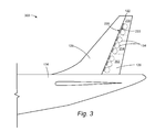
- an enhanced flow control tail 300 has the active flow control actuators 134 mounted within the rudder 128 rather than within the vertical stabilizer 126. In doing so, the actuating flow from the active flow control actuators 134 interacts with the ambient flow on the rudder itself, proximate to the leading edge 222 of the rudder. Because flow separation commonly occurs on the rudder aft of the leading edge 222, placement of the active flow control actuators 134 within the rudder 128 may be advantageous.
- structural limitations within the rudder 126 may influence the positioning of the active flow control actuators 134 within the vertical stabilizer 126 so that the actuating flow from the actuators interacts with the ambient flow close to the trailing edge 220 of the stabilizer to maximize the effect on the flow separation over the rudder 128.
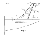
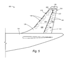
- FIGURE 4 A further embodiment is shown in FIGURE 4 , with an enhanced flow control tail 400 that includes two groupings of linearly aligned active flow control actuators 134. The first is mounted within the vertical stabilizer 126 near the leading edge 218. The second is mounted within the vertical stabilizer 126 near the trailing edge 220. Yet another embodiment is shown in FIGURE 5 , with an enhanced flow control tail 500 that again includes two groupings of linearly aligned active flow control actuators 134. However, according to this embodiment, the first grouping of active flow control actuators 134 is mounted within the vertical stabilizer 126 near the leading edge 218, while the second grouping of active flow control actuators 134 is mounted within the rudder 128 near the leading edge 222. It should be appreciated that alternative embodiments could include third or fourth groupings of active flow control actuators 134 positioned at the trailing edge 220 of the vertical stabilizer 126 and/or at the trailing edge 224 of the rudder 128.
- the active flow control system 130 includes an actuator control system 132 and a number of active flow control actuators 134.
- the actuator control system 132 includes an event detection system 602 for collection of data corresponding to flow control events, a detection system controller 604 for interpretation of the data from the sensors of the event detection system 602 to determine that a flow control event has occurred, and an active flow control actuator (AFCA) controller 606 for identifying the active flow control actuators 134 for activation in response to the determination that the flow control event occurred, and to activate the appropriate active flow control actuators 134.
- AFCA active flow control actuator
- the event detection system 602 may include any number and type of sensors, including but not limited to the pressure sensors 210, the rudder deflection sensor 212, the control input sensors 214, and the flight parameter sensors 216.
- the event detection system 602 transmits the sensor data to the detection system controller 604, which makes a determination as to whether a flow control event has occurred. This determination and all appropriate data, such as the type of event, the location of the event, and the severity of the event, is forwarded to the AFCA controller 606.
- the AFCA controller 606 utilizes this flow control event data to select the appropriate active flow control actuators 134, either all of the available active flow control actuators 134 or a subset of active flow control actuators 134 with a determined zone, and to activate those actuators.
- the detection system controller 604 and the AFCA controller 606 may be separate controllers or may be a single controller operative to perform the functionality of both controllers. Each controller may be computer hardware and/or software programmed to perform the operations described herein.
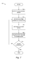
- the routine 600 begins at operation 702, where a flow control event is detected.
- the flow control event may be a flow separation indicator or any other data collected from one or more sensors of the event detection system 602. This determination that a flow control event has occurred may be made by the detection system controller 604 or the AFCA controller 606.
- routine 600 continues to operation 704, where the AFCA controller 606 determines according to the flow control event data which active flow control actuators 134 or zone of active flow control actuators 134 are to be activated to control the airflow over the vertical control surface 122.
- the routine 600 continues to operation 706, where the AFCA controller 606 determines the power input levels for activating the selected active flow control actuators 134.
- the active flow control actuators 134 may be operated at less than full power to conserve aircraft power. This determination may depend on the magnitude of the flow control event, the location of the event, and the number and positioning of the available active flow control actuators 134.
- the AFCA controller 606 activates the selected active flow control actuators 134 according to the determined zones and power levels. From operation 708, the routine 600 continues to operation 710, where a determination is made as to whether the flow control event has completed. If the event is no longer applicable, such as when the conditions causing flow separation have concluded, then the routine 600 ends. However, if at operation 710, a determination is made that the flow control event has not concluded, then the routine 600 returns to operation 704 and continues as described above.
Landscapes
- Engineering & Computer Science (AREA)
- Aviation & Aerospace Engineering (AREA)
- Traffic Control Systems (AREA)
- Feedback Control In General (AREA)
- Fluid-Damping Devices (AREA)
- Aerodynamic Tests, Hydrodynamic Tests, Wind Tunnels, And Water Tanks (AREA)
Priority Applications (1)
| Application Number | Priority Date | Filing Date | Title |
|---|---|---|---|
| EP16199645.9A EP3150485B1 (de) | 2010-10-13 | 2011-10-03 | Aktive flusssteuerung auf einem vertikalen stabilisator und ruder |
Applications Claiming Priority (1)
| Application Number | Priority Date | Filing Date | Title |
|---|---|---|---|
| US12/903,720 US9090326B2 (en) | 2010-10-13 | 2010-10-13 | Active flow control on a vertical stabilizer and rudder |
Related Child Applications (2)
| Application Number | Title | Priority Date | Filing Date |
|---|---|---|---|
| EP16199645.9A Division EP3150485B1 (de) | 2010-10-13 | 2011-10-03 | Aktive flusssteuerung auf einem vertikalen stabilisator und ruder |
| EP16199645.9A Division-Into EP3150485B1 (de) | 2010-10-13 | 2011-10-03 | Aktive flusssteuerung auf einem vertikalen stabilisator und ruder |
Publications (3)
| Publication Number | Publication Date |
|---|---|
| EP2441669A2 true EP2441669A2 (de) | 2012-04-18 |
| EP2441669A3 EP2441669A3 (de) | 2014-05-14 |
| EP2441669B1 EP2441669B1 (de) | 2017-01-04 |
Family
ID=44903080
Family Applications (2)
| Application Number | Title | Priority Date | Filing Date |
|---|---|---|---|
| EP11183674.8A Active EP2441669B1 (de) | 2010-10-13 | 2011-10-03 | Aktive Strömungsssteuerung auf einer Heckflosse mit einem Seitenruder |
| EP16199645.9A Active EP3150485B1 (de) | 2010-10-13 | 2011-10-03 | Aktive flusssteuerung auf einem vertikalen stabilisator und ruder |
Family Applications After (1)
| Application Number | Title | Priority Date | Filing Date |
|---|---|---|---|
| EP16199645.9A Active EP3150485B1 (de) | 2010-10-13 | 2011-10-03 | Aktive flusssteuerung auf einem vertikalen stabilisator und ruder |
Country Status (3)
| Country | Link |
|---|---|
| US (1) | US9090326B2 (de) |
| EP (2) | EP2441669B1 (de) |
| CN (2) | CN110282118B (de) |
Cited By (7)
| Publication number | Priority date | Publication date | Assignee | Title |
|---|---|---|---|---|
| EP2660149A3 (de) * | 2012-05-02 | 2015-06-10 | The Boeing Company | Dielektrisches Sperrentladungsflugsteuerungssystem durch modulierten Grenzschichtübergang |
| EP3150486A1 (de) * | 2015-10-01 | 2017-04-05 | Airbus Operations GmbH | Wirbelgeneratoranordnung, stromsteuerungssystem und verfahren zur steuerung eines stroms auf einer ruderoberfläche |
| US20170152025A1 (en) * | 2015-12-01 | 2017-06-01 | Airbus Operations Gmbh | Vortex generator arrangement for an aircraft |
| US9849966B2 (en) | 2015-12-18 | 2017-12-26 | The Boeing Company | Fuselage structure for accommodating tails and canards of different sizes and shapes |
| US10787245B2 (en) | 2016-06-01 | 2020-09-29 | The Boeing Company | Distributed compressor for improved integration and performance of an active fluid flow control system |
| US11332232B2 (en) | 2019-08-29 | 2022-05-17 | The Boeing Company | Vertical tail structure having symmetry action slats |
| EP4015371A1 (de) * | 2020-12-18 | 2022-06-22 | Airbus Operations Limited | Strömungsabrissauslösungssystem |
Families Citing this family (32)
| Publication number | Priority date | Publication date | Assignee | Title |
|---|---|---|---|---|
| FR2945790B1 (fr) * | 2009-05-20 | 2011-07-22 | Airbus France | Procede pour l'amelioration de l'efficacite aerodynamique de l'empennage vertical d'un aeronef. |
| FR2973774B1 (fr) * | 2011-04-06 | 2015-05-08 | Airbus Operations Sas | Procede d'amelioration de l'efficacite aerodynamique d'un empennage vertical d'aeronef. |
| US20120319826A1 (en) * | 2011-06-14 | 2012-12-20 | Astronics Advanced Electronic Systems Corp. | Power Line Data Communication Using Current Modulation |
| US20160152324A1 (en) * | 2013-04-01 | 2016-06-02 | California Institute Of Technology | Fluidic fence for performance enhancement |
| US9371799B2 (en) | 2014-04-24 | 2016-06-21 | The Boeing Company | Thrust-reverser assemblies that utilize active flow-control and systems and methods including the same |
| US9559287B2 (en) | 2014-07-11 | 2017-01-31 | The Boeing Company | Orthotropic bimorph for improved performance synthetic jet |
| USD764384S1 (en) * | 2014-07-15 | 2016-08-23 | Icon Aircraft, Inc. | Aircraft delta fin |
| CN104149969B (zh) * | 2014-08-26 | 2015-06-10 | 西北工业大学 | 一种可实现内部协同射流的螺旋桨布局构型 |
| US10316753B2 (en) | 2014-09-19 | 2019-06-11 | The Boeing Company | Pre-cooler inlet ducts that utilize active flow-control and systems and methods including the same |
| US9789956B2 (en) | 2014-09-19 | 2017-10-17 | The Boeing Company | Vortex generators responsive to ambient conditions |
| US10358208B2 (en) * | 2014-12-01 | 2019-07-23 | The United States Of America As Represented By The Administrator Of Nasa | Hybrid flow control method for simple hinged flap high-lift system |
| US9889924B2 (en) * | 2015-08-24 | 2018-02-13 | The Boeing Company | Multi-directional control using upper surface blowing systems |
| US10086927B2 (en) | 2016-04-18 | 2018-10-02 | The Boeing Company | Thermally controlled active flow control system |
| US11085471B2 (en) | 2016-06-22 | 2021-08-10 | Quest Integrated, Llc | Active control of vortices for skin friction reduction |
| US10364021B2 (en) * | 2016-09-26 | 2019-07-30 | General Electric Company | Aircraft having an aft engine and stabilizer root fillet |
| US10622543B2 (en) | 2017-01-11 | 2020-04-14 | The Boeing Company | Piezoelectric bimorph disk outer boundary design and method for performance optimization |
| CN106585945A (zh) * | 2017-01-13 | 2017-04-26 | 中国科学院光电研究院 | 飞艇姿态调整的主动流动控制装置及方法、固定其的装置 |
| US11124290B2 (en) * | 2017-06-21 | 2021-09-21 | Advanced Fluidics LLC | Integrated aerodynamic flow control system with air source |
| GB201719016D0 (en) * | 2017-11-17 | 2018-01-03 | Airbus Operations Gmbh | Vortex generator arrangement and control system for an aircraft |
| JP2021509377A (ja) * | 2017-12-28 | 2021-03-25 | エアロ デザイン ラボラトリーズ,インコーポレイテッド | 横方向ダクト出口流の抵抗を低減するための装置 |
| EP3746362B1 (de) * | 2018-01-31 | 2024-03-06 | Airbus Operations GmbH | Tragfläche zur strömungssteuerung |
| JP7158119B2 (ja) * | 2018-05-08 | 2022-10-21 | 株式会社Subaru | 航空機の操舵システム及び航空機 |
| CN109591329A (zh) * | 2018-10-25 | 2019-04-09 | 江苏恒神股份有限公司 | 一种碳纤维全高度泡沫夹芯复合材料舵面结构及其制备方法 |
| US10981645B2 (en) * | 2018-11-27 | 2021-04-20 | The Boeing Company | Drag reduction systems for aircraft |
| CN110697024B (zh) * | 2019-10-14 | 2022-07-15 | 中国航空工业集团公司西安飞机设计研究所 | 一种飞机尾翼结构 |
| US11643190B2 (en) * | 2020-01-30 | 2023-05-09 | Airbus Operations Gmbh | Vortex generator apparatus for an aircraft |
| US11142302B1 (en) | 2020-03-28 | 2021-10-12 | Textron Innovations Inc. | Fluidic split flap systems for yaw control in forward flight |
| US12040730B2 (en) * | 2020-05-21 | 2024-07-16 | The Boeing Company | Active flow control systems and methods for aircraft |
| CN113460299B (zh) * | 2021-09-02 | 2021-11-30 | 中国空气动力研究与发展中心低速空气动力研究所 | 一种用于共轴刚性旋翼桨毂减阻的射流结构及其使用方法 |
| CN113879512B (zh) * | 2021-11-16 | 2024-04-26 | 中国商用飞机有限责任公司 | 航向增效系统及具有航向增效系统的翼身融合布局飞行器 |
| DE102022103381B3 (de) | 2022-02-14 | 2023-07-06 | Deutsches Zentrum für Luft- und Raumfahrt e.V. | Verfahren zur Bestimmung von Anströmparametern einesÜberschall-Flugkörpers |
| JP2024106285A (ja) * | 2023-01-26 | 2024-08-07 | 株式会社Subaru | ヘリコプタ、ヘリコプタの垂直尾翼、ヘリコプタの垂直尾翼の改修方法及びヘリコプタのテールロータによるアンチトルクの向上方法 |
Family Cites Families (39)
| Publication number | Priority date | Publication date | Assignee | Title |
|---|---|---|---|---|
| US2387526A (en) * | 1943-05-19 | 1945-10-23 | Curtiss Wright Corp | Airplane |
| US2938680A (en) * | 1957-07-02 | 1960-05-31 | North American Aviation Inc | Multiple position airfoil slat |
| US4213587A (en) * | 1978-12-04 | 1980-07-22 | The Boeing Company | Hinge arrangement for control surfaces |
| US4299442A (en) | 1980-04-14 | 1981-11-10 | Buckelew Arthur L | Aircraft visual collision and avoidance device |
| US4395007A (en) * | 1980-11-13 | 1983-07-26 | Rockwell International Corporation | Actuation system for a control surface of an aircraft |
| DE3043567C2 (de) * | 1980-11-15 | 1982-09-23 | Deutsche Forschungs- und Versuchsanstalt für Luft- und Raumfahrt e.V., 5000 Köln | Anordnung zur Beeinflussung der Strömung an aerodynamischen Profilen |
| US4633376A (en) | 1985-07-15 | 1986-12-30 | The Boeing Company | Advanced fuel receptacle lighting system for aerial refueling |
| US5222699A (en) * | 1990-04-16 | 1993-06-29 | Ltv Aerospace And Defense Company | Variable control aircraft control surface |
| US5458304A (en) | 1992-08-26 | 1995-10-17 | Gilbert; Raymond D. | Disk spoiler system |
| US5282591A (en) * | 1992-12-21 | 1994-02-01 | The United States Of America As Represented By The Secretary Of The Navy | Active vortex control for a high performance wing |
| US5884872A (en) * | 1993-05-26 | 1999-03-23 | The United States Of America As Represented By The Secretary Of The Navy | Oscillating flap lift enhancement device |
| US5825305A (en) | 1995-05-04 | 1998-10-20 | Mcdonnell Douglas Corporation | Cargo loading alignment device |
| US5758823A (en) * | 1995-06-12 | 1998-06-02 | Georgia Tech Research Corporation | Synthetic jet actuator and applications thereof |
| US5806805A (en) * | 1996-08-07 | 1998-09-15 | The Boeing Company | Fault tolerant actuation system for flight control actuators |
| DE19643069C2 (de) * | 1996-10-18 | 1999-03-25 | Daimler Benz Aerospace Airbus | Seitenleitwerksstrukur für ein Flugzeug |
| US5983944A (en) | 1998-03-20 | 1999-11-16 | Niv; Shaul E. | Apparatus for active fluid control |
| US6412732B1 (en) | 1999-07-06 | 2002-07-02 | Georgia Tech Research Corporation | Apparatus and method for enhancement of aerodynamic performance by using pulse excitation control |
| US6371414B1 (en) | 1999-07-16 | 2002-04-16 | Lockheed Martin Corporation | System and method for manipulating and controlling fluid flow over a surface |
| US6486798B2 (en) | 2000-05-11 | 2002-11-26 | Rastar Corporation | System and method of preventing aircraft wing damage |
| WO2002072421A2 (en) | 2001-03-10 | 2002-09-19 | Georgia Tech Research Corporation | Modification of fluid flow about bodies and surfaces through virtual aero-shaping of airfoils with synthetic jet actuators |
| US6634597B2 (en) * | 2002-01-11 | 2003-10-21 | The Boeing Company | Method and apparatus for controlling aircraft airflow |
| US6837465B2 (en) | 2003-01-03 | 2005-01-04 | Orbital Research Inc | Flow control device and method of controlling flow |
| US6923405B2 (en) * | 2003-11-17 | 2005-08-02 | The Boeing Company | Enhanced rudder control system |
| US7537182B2 (en) | 2004-09-23 | 2009-05-26 | The United States Of America As Represented By The Administrator Of The National Aeronautics And Space Administration | Simultaneous multiple-location separation control |
| US7686257B2 (en) * | 2005-05-23 | 2010-03-30 | Lockheed Martin Corporation | Dual bimorph synthetic pulsator |
| US7967258B2 (en) * | 2005-10-06 | 2011-06-28 | Lockheed Martin Corporation | Dual bimorph synthetic pulsator |
| US7600714B2 (en) * | 2006-04-20 | 2009-10-13 | Honeywell International Inc. | Diffusing air inlet door assembly |
| US7624941B1 (en) | 2006-05-02 | 2009-12-01 | Orbital Research Inc. | Method of controlling aircraft, missiles, munitions and ground vehicles with plasma actuators |
| US7874525B2 (en) * | 2006-05-04 | 2011-01-25 | Lockheed Martin Corporation | Method and system for fully fixed vehicle control surfaces |
| US7988101B2 (en) * | 2007-05-25 | 2011-08-02 | The Boeing Company | Airfoil trailing edge plasma flow control apparatus and method |
| US8016247B2 (en) * | 2007-05-25 | 2011-09-13 | The Boeing Company | Plasma flow control actuator system and method |
| US7913949B2 (en) | 2007-06-11 | 2011-03-29 | The Boeing Company | Symmetric leading edge device and method to delay flow separation |
| GB0722415D0 (en) * | 2007-11-15 | 2007-12-27 | Airbus Uk Ltd | Aircraft wing and flap deployment system |
| ES2345584B1 (es) * | 2007-12-21 | 2011-07-18 | Airbus Operations, S.L. | Superficie de control de aeronave. |
| JP2009251027A (ja) | 2008-04-01 | 2009-10-29 | Japan Aerospace Exploration Agency | 再帰性投影ヘッドアップディスプレイ |
| US9239039B2 (en) * | 2008-10-27 | 2016-01-19 | General Electric Company | Active circulation control of aerodynamic structures |
| CN101508338A (zh) * | 2009-03-31 | 2009-08-19 | 北京航空航天大学 | 等离子体格尼襟翼 |
| FR2945790B1 (fr) * | 2009-05-20 | 2011-07-22 | Airbus France | Procede pour l'amelioration de l'efficacite aerodynamique de l'empennage vertical d'un aeronef. |
| FR2946022B1 (fr) | 2009-05-26 | 2013-02-08 | Airbus France | Systeme de protection de zones dangereuses. |
-
2010
- 2010-10-13 US US12/903,720 patent/US9090326B2/en active Active
-
2011
- 2011-10-03 EP EP11183674.8A patent/EP2441669B1/de active Active
- 2011-10-03 EP EP16199645.9A patent/EP3150485B1/de active Active
- 2011-10-13 CN CN201910588804.0A patent/CN110282118B/zh active Active
- 2011-10-13 CN CN201110317725XA patent/CN102442428A/zh active Pending
Cited By (11)
| Publication number | Priority date | Publication date | Assignee | Title |
|---|---|---|---|---|
| EP2660149A3 (de) * | 2012-05-02 | 2015-06-10 | The Boeing Company | Dielektrisches Sperrentladungsflugsteuerungssystem durch modulierten Grenzschichtübergang |
| EP3150486A1 (de) * | 2015-10-01 | 2017-04-05 | Airbus Operations GmbH | Wirbelgeneratoranordnung, stromsteuerungssystem und verfahren zur steuerung eines stroms auf einer ruderoberfläche |
| US10279894B2 (en) | 2015-10-01 | 2019-05-07 | Airbus Operations Gmbh | Vortex generator arrangement, flow control system and method for controlling a flow on a rudder surface |
| US20170152025A1 (en) * | 2015-12-01 | 2017-06-01 | Airbus Operations Gmbh | Vortex generator arrangement for an aircraft |
| EP3176082A1 (de) * | 2015-12-01 | 2017-06-07 | Airbus Operations GmbH | Wirbelgeneratoranordnung für ein luftfahrzeug |
| US10543908B2 (en) | 2015-12-01 | 2020-01-28 | Airbus Operations Gmbh | Vortex generator arrangement for an aircraft |
| US9849966B2 (en) | 2015-12-18 | 2017-12-26 | The Boeing Company | Fuselage structure for accommodating tails and canards of different sizes and shapes |
| US10787245B2 (en) | 2016-06-01 | 2020-09-29 | The Boeing Company | Distributed compressor for improved integration and performance of an active fluid flow control system |
| US11332232B2 (en) | 2019-08-29 | 2022-05-17 | The Boeing Company | Vertical tail structure having symmetry action slats |
| EP4015371A1 (de) * | 2020-12-18 | 2022-06-22 | Airbus Operations Limited | Strömungsabrissauslösungssystem |
| CN114715383A (zh) * | 2020-12-18 | 2022-07-08 | 空中客车营运有限公司 | 失速触发器系统 |
Also Published As
| Publication number | Publication date |
|---|---|
| CN110282118A (zh) | 2019-09-27 |
| US20120091266A1 (en) | 2012-04-19 |
| EP3150485A1 (de) | 2017-04-05 |
| US9090326B2 (en) | 2015-07-28 |
| EP2441669A3 (de) | 2014-05-14 |
| EP3150485B1 (de) | 2018-12-12 |
| CN110282118B (zh) | 2023-02-24 |
| CN102442428A (zh) | 2012-05-09 |
| EP2441669B1 (de) | 2017-01-04 |
Similar Documents
| Publication | Publication Date | Title |
|---|---|---|
| EP3150485B1 (de) | Aktive flusssteuerung auf einem vertikalen stabilisator und ruder | |
| CN101557981B (zh) | 航空移动平台及改善其性能的方法 | |
| US7264200B2 (en) | System and method for improved rotor tip performance | |
| EP2540621B1 (de) | Steuersystem für ein flugzeug, verfahren zur steuerung eines flugzeugs und flugzeug | |
| US7367530B2 (en) | Aerospace vehicle yaw generating systems and associated methods | |
| US20040079835A1 (en) | Control system for alleviating a gust load on an aircraft wing | |
| US10351226B2 (en) | Systems and methods for controlling a magnitude of a sonic boom | |
| US20180043992A1 (en) | Horizontal tail load optimization system and method | |
| WO2009023352A2 (en) | Controllable winglets | |
| EP2520995A2 (de) | Flugzeug mit einer Vorrichtung zur direktionalen Stabilisierung des Flugzeugs, Computerprogrammprodukt und Verfahren zur direktionalen Stabilisierung des Flugzeugs | |
| WO2001005654A2 (en) | Vehicle control system and method using a control surface and a geared tab | |
| JP7385254B2 (ja) | 電動化航空機及びその姿勢制御方法 | |
| EP4345000B1 (de) | Flugsteuerfläche | |
| EP3476725B1 (de) | Verfahren und systeme zur steuerung der flugzeugflugleistung | |
| JP2001010594A (ja) | 境界層制御装置および境界層制御方法 |
Legal Events
| Date | Code | Title | Description |
|---|---|---|---|
| PUAI | Public reference made under article 153(3) epc to a published international application that has entered the european phase |
Free format text: ORIGINAL CODE: 0009012 |
|
| 17P | Request for examination filed |
Effective date: 20111003 |
|
| AK | Designated contracting states |
Kind code of ref document: A2 Designated state(s): AL AT BE BG CH CY CZ DE DK EE ES FI FR GB GR HR HU IE IS IT LI LT LU LV MC MK MT NL NO PL PT RO RS SE SI SK SM TR |
|
| AX | Request for extension of the european patent |
Extension state: BA ME |
|
| PUAL | Search report despatched |
Free format text: ORIGINAL CODE: 0009013 |
|
| AK | Designated contracting states |
Kind code of ref document: A3 Designated state(s): AL AT BE BG CH CY CZ DE DK EE ES FI FR GB GR HR HU IE IS IT LI LT LU LV MC MK MT NL NO PL PT RO RS SE SI SK SM TR |
|
| AX | Request for extension of the european patent |
Extension state: BA ME |
|
| RIC1 | Information provided on ipc code assigned before grant |
Ipc: B64C 23/00 20060101ALI20140407BHEP Ipc: B64C 5/06 20060101AFI20140407BHEP Ipc: B64C 21/00 20060101ALI20140407BHEP Ipc: B64C 23/06 20060101ALI20140407BHEP |
|
| 17Q | First examination report despatched |
Effective date: 20141223 |
|
| GRAP | Despatch of communication of intention to grant a patent |
Free format text: ORIGINAL CODE: EPIDOSNIGR1 |
|
| INTG | Intention to grant announced |
Effective date: 20160715 |
|
| GRAS | Grant fee paid |
Free format text: ORIGINAL CODE: EPIDOSNIGR3 |
|
| GRAA | (expected) grant |
Free format text: ORIGINAL CODE: 0009210 |
|
| AK | Designated contracting states |
Kind code of ref document: B1 Designated state(s): AL AT BE BG CH CY CZ DE DK EE ES FI FR GB GR HR HU IE IS IT LI LT LU LV MC MK MT NL NO PL PT RO RS SE SI SK SM TR |
|
| REG | Reference to a national code |
Ref country code: GB Ref legal event code: FG4D |
|
| REG | Reference to a national code |
Ref country code: CH Ref legal event code: EP |
|
| REG | Reference to a national code |
Ref country code: AT Ref legal event code: REF Ref document number: 858951 Country of ref document: AT Kind code of ref document: T Effective date: 20170115 |
|
| REG | Reference to a national code |
Ref country code: IE Ref legal event code: FG4D |
|
| REG | Reference to a national code |
Ref country code: DE Ref legal event code: R096 Ref document number: 602011033981 Country of ref document: DE |
|
| REG | Reference to a national code |
Ref country code: LT Ref legal event code: MG4D Ref country code: NL Ref legal event code: MP Effective date: 20170104 |
|
| REG | Reference to a national code |
Ref country code: AT Ref legal event code: MK05 Ref document number: 858951 Country of ref document: AT Kind code of ref document: T Effective date: 20170104 |
|
| PG25 | Lapsed in a contracting state [announced via postgrant information from national office to epo] |
Ref country code: NL Free format text: LAPSE BECAUSE OF FAILURE TO SUBMIT A TRANSLATION OF THE DESCRIPTION OR TO PAY THE FEE WITHIN THE PRESCRIBED TIME-LIMIT Effective date: 20170104 |
|
| PG25 | Lapsed in a contracting state [announced via postgrant information from national office to epo] |
Ref country code: NO Free format text: LAPSE BECAUSE OF FAILURE TO SUBMIT A TRANSLATION OF THE DESCRIPTION OR TO PAY THE FEE WITHIN THE PRESCRIBED TIME-LIMIT Effective date: 20170404 Ref country code: GR Free format text: LAPSE BECAUSE OF FAILURE TO SUBMIT A TRANSLATION OF THE DESCRIPTION OR TO PAY THE FEE WITHIN THE PRESCRIBED TIME-LIMIT Effective date: 20170405 Ref country code: IS Free format text: LAPSE BECAUSE OF FAILURE TO SUBMIT A TRANSLATION OF THE DESCRIPTION OR TO PAY THE FEE WITHIN THE PRESCRIBED TIME-LIMIT Effective date: 20170504 Ref country code: FI Free format text: LAPSE BECAUSE OF FAILURE TO SUBMIT A TRANSLATION OF THE DESCRIPTION OR TO PAY THE FEE WITHIN THE PRESCRIBED TIME-LIMIT Effective date: 20170104 Ref country code: LT Free format text: LAPSE BECAUSE OF FAILURE TO SUBMIT A TRANSLATION OF THE DESCRIPTION OR TO PAY THE FEE WITHIN THE PRESCRIBED TIME-LIMIT Effective date: 20170104 Ref country code: HR Free format text: LAPSE BECAUSE OF FAILURE TO SUBMIT A TRANSLATION OF THE DESCRIPTION OR TO PAY THE FEE WITHIN THE PRESCRIBED TIME-LIMIT Effective date: 20170104 |
|
| PG25 | Lapsed in a contracting state [announced via postgrant information from national office to epo] |
Ref country code: PL Free format text: LAPSE BECAUSE OF FAILURE TO SUBMIT A TRANSLATION OF THE DESCRIPTION OR TO PAY THE FEE WITHIN THE PRESCRIBED TIME-LIMIT Effective date: 20170104 Ref country code: AT Free format text: LAPSE BECAUSE OF FAILURE TO SUBMIT A TRANSLATION OF THE DESCRIPTION OR TO PAY THE FEE WITHIN THE PRESCRIBED TIME-LIMIT Effective date: 20170104 Ref country code: RS Free format text: LAPSE BECAUSE OF FAILURE TO SUBMIT A TRANSLATION OF THE DESCRIPTION OR TO PAY THE FEE WITHIN THE PRESCRIBED TIME-LIMIT Effective date: 20170104 Ref country code: SE Free format text: LAPSE BECAUSE OF FAILURE TO SUBMIT A TRANSLATION OF THE DESCRIPTION OR TO PAY THE FEE WITHIN THE PRESCRIBED TIME-LIMIT Effective date: 20170104 Ref country code: LV Free format text: LAPSE BECAUSE OF FAILURE TO SUBMIT A TRANSLATION OF THE DESCRIPTION OR TO PAY THE FEE WITHIN THE PRESCRIBED TIME-LIMIT Effective date: 20170104 Ref country code: ES Free format text: LAPSE BECAUSE OF FAILURE TO SUBMIT A TRANSLATION OF THE DESCRIPTION OR TO PAY THE FEE WITHIN THE PRESCRIBED TIME-LIMIT Effective date: 20170104 Ref country code: BG Free format text: LAPSE BECAUSE OF FAILURE TO SUBMIT A TRANSLATION OF THE DESCRIPTION OR TO PAY THE FEE WITHIN THE PRESCRIBED TIME-LIMIT Effective date: 20170404 Ref country code: PT Free format text: LAPSE BECAUSE OF FAILURE TO SUBMIT A TRANSLATION OF THE DESCRIPTION OR TO PAY THE FEE WITHIN THE PRESCRIBED TIME-LIMIT Effective date: 20170504 |
|
| REG | Reference to a national code |
Ref country code: DE Ref legal event code: R097 Ref document number: 602011033981 Country of ref document: DE |
|
| REG | Reference to a national code |
Ref country code: FR Ref legal event code: PLFP Year of fee payment: 7 |
|
| PG25 | Lapsed in a contracting state [announced via postgrant information from national office to epo] |
Ref country code: IT Free format text: LAPSE BECAUSE OF FAILURE TO SUBMIT A TRANSLATION OF THE DESCRIPTION OR TO PAY THE FEE WITHIN THE PRESCRIBED TIME-LIMIT Effective date: 20170104 Ref country code: CZ Free format text: LAPSE BECAUSE OF FAILURE TO SUBMIT A TRANSLATION OF THE DESCRIPTION OR TO PAY THE FEE WITHIN THE PRESCRIBED TIME-LIMIT Effective date: 20170104 Ref country code: SK Free format text: LAPSE BECAUSE OF FAILURE TO SUBMIT A TRANSLATION OF THE DESCRIPTION OR TO PAY THE FEE WITHIN THE PRESCRIBED TIME-LIMIT Effective date: 20170104 Ref country code: EE Free format text: LAPSE BECAUSE OF FAILURE TO SUBMIT A TRANSLATION OF THE DESCRIPTION OR TO PAY THE FEE WITHIN THE PRESCRIBED TIME-LIMIT Effective date: 20170104 Ref country code: RO Free format text: LAPSE BECAUSE OF FAILURE TO SUBMIT A TRANSLATION OF THE DESCRIPTION OR TO PAY THE FEE WITHIN THE PRESCRIBED TIME-LIMIT Effective date: 20170104 |
|
| PLBE | No opposition filed within time limit |
Free format text: ORIGINAL CODE: 0009261 |
|
| STAA | Information on the status of an ep patent application or granted ep patent |
Free format text: STATUS: NO OPPOSITION FILED WITHIN TIME LIMIT |
|
| PG25 | Lapsed in a contracting state [announced via postgrant information from national office to epo] |
Ref country code: DK Free format text: LAPSE BECAUSE OF FAILURE TO SUBMIT A TRANSLATION OF THE DESCRIPTION OR TO PAY THE FEE WITHIN THE PRESCRIBED TIME-LIMIT Effective date: 20170104 Ref country code: SM Free format text: LAPSE BECAUSE OF FAILURE TO SUBMIT A TRANSLATION OF THE DESCRIPTION OR TO PAY THE FEE WITHIN THE PRESCRIBED TIME-LIMIT Effective date: 20170104 |
|
| 26N | No opposition filed |
Effective date: 20171005 |
|
| PG25 | Lapsed in a contracting state [announced via postgrant information from national office to epo] |
Ref country code: SI Free format text: LAPSE BECAUSE OF FAILURE TO SUBMIT A TRANSLATION OF THE DESCRIPTION OR TO PAY THE FEE WITHIN THE PRESCRIBED TIME-LIMIT Effective date: 20170104 |
|
| PG25 | Lapsed in a contracting state [announced via postgrant information from national office to epo] |
Ref country code: MC Free format text: LAPSE BECAUSE OF FAILURE TO SUBMIT A TRANSLATION OF THE DESCRIPTION OR TO PAY THE FEE WITHIN THE PRESCRIBED TIME-LIMIT Effective date: 20170104 |
|
| REG | Reference to a national code |
Ref country code: CH Ref legal event code: PL |
|
| REG | Reference to a national code |
Ref country code: IE Ref legal event code: MM4A |
|
| PG25 | Lapsed in a contracting state [announced via postgrant information from national office to epo] |
Ref country code: LI Free format text: LAPSE BECAUSE OF NON-PAYMENT OF DUE FEES Effective date: 20171031 Ref country code: LU Free format text: LAPSE BECAUSE OF NON-PAYMENT OF DUE FEES Effective date: 20171003 Ref country code: CH Free format text: LAPSE BECAUSE OF NON-PAYMENT OF DUE FEES Effective date: 20171031 |
|
| REG | Reference to a national code |
Ref country code: BE Ref legal event code: MM Effective date: 20171031 |
|
| PG25 | Lapsed in a contracting state [announced via postgrant information from national office to epo] |
Ref country code: BE Free format text: LAPSE BECAUSE OF NON-PAYMENT OF DUE FEES Effective date: 20171031 |
|
| PG25 | Lapsed in a contracting state [announced via postgrant information from national office to epo] |
Ref country code: MT Free format text: LAPSE BECAUSE OF NON-PAYMENT OF DUE FEES Effective date: 20171003 |
|
| REG | Reference to a national code |
Ref country code: FR Ref legal event code: PLFP Year of fee payment: 8 |
|
| PG25 | Lapsed in a contracting state [announced via postgrant information from national office to epo] |
Ref country code: IE Free format text: LAPSE BECAUSE OF NON-PAYMENT OF DUE FEES Effective date: 20171003 |
|
| PG25 | Lapsed in a contracting state [announced via postgrant information from national office to epo] |
Ref country code: HU Free format text: LAPSE BECAUSE OF FAILURE TO SUBMIT A TRANSLATION OF THE DESCRIPTION OR TO PAY THE FEE WITHIN THE PRESCRIBED TIME-LIMIT; INVALID AB INITIO Effective date: 20111003 |
|
| PG25 | Lapsed in a contracting state [announced via postgrant information from national office to epo] |
Ref country code: CY Free format text: LAPSE BECAUSE OF NON-PAYMENT OF DUE FEES Effective date: 20170104 |
|
| PG25 | Lapsed in a contracting state [announced via postgrant information from national office to epo] |
Ref country code: MK Free format text: LAPSE BECAUSE OF FAILURE TO SUBMIT A TRANSLATION OF THE DESCRIPTION OR TO PAY THE FEE WITHIN THE PRESCRIBED TIME-LIMIT Effective date: 20170104 |
|
| REG | Reference to a national code |
Ref country code: DE Ref legal event code: R082 Ref document number: 602011033981 Country of ref document: DE Representative=s name: MAIER, LL.M., MICHAEL C., DE Ref country code: DE Ref legal event code: R082 Ref document number: 602011033981 Country of ref document: DE Representative=s name: BOULT WADE TENNANT LLP, DE |
|
| REG | Reference to a national code |
Ref country code: DE Ref legal event code: R082 Ref document number: 602011033981 Country of ref document: DE Representative=s name: BOULT WADE TENNANT LLP, DE |
|
| PG25 | Lapsed in a contracting state [announced via postgrant information from national office to epo] |
Ref country code: TR Free format text: LAPSE BECAUSE OF FAILURE TO SUBMIT A TRANSLATION OF THE DESCRIPTION OR TO PAY THE FEE WITHIN THE PRESCRIBED TIME-LIMIT Effective date: 20170104 |
|
| PG25 | Lapsed in a contracting state [announced via postgrant information from national office to epo] |
Ref country code: AL Free format text: LAPSE BECAUSE OF FAILURE TO SUBMIT A TRANSLATION OF THE DESCRIPTION OR TO PAY THE FEE WITHIN THE PRESCRIBED TIME-LIMIT Effective date: 20170104 |
|
| P01 | Opt-out of the competence of the unified patent court (upc) registered |
Effective date: 20230516 |
|
| PGFP | Annual fee paid to national office [announced via postgrant information from national office to epo] |
Ref country code: DE Payment date: 20251029 Year of fee payment: 15 |
|
| PGFP | Annual fee paid to national office [announced via postgrant information from national office to epo] |
Ref country code: GB Payment date: 20251027 Year of fee payment: 15 |
|
| PGFP | Annual fee paid to national office [announced via postgrant information from national office to epo] |
Ref country code: FR Payment date: 20251027 Year of fee payment: 15 |