EP2441431B1 - Behälter für die Herstellung einer konditionierten Blutzusammensetzung - Google Patents
Behälter für die Herstellung einer konditionierten Blutzusammensetzung Download PDFInfo
- Publication number
- EP2441431B1 EP2441431B1 EP11176691.1A EP11176691A EP2441431B1 EP 2441431 B1 EP2441431 B1 EP 2441431B1 EP 11176691 A EP11176691 A EP 11176691A EP 2441431 B1 EP2441431 B1 EP 2441431B1
- Authority
- EP
- European Patent Office
- Prior art keywords
- container
- blood
- syringe
- filling opening
- container according
- Prior art date
- Legal status (The legal status is an assumption and is not a legal conclusion. Google has not performed a legal analysis and makes no representation as to the accuracy of the status listed.)
- Active
Links
Images

Classifications
-
- A—HUMAN NECESSITIES
- A61—MEDICAL OR VETERINARY SCIENCE; HYGIENE
- A61J—CONTAINERS SPECIALLY ADAPTED FOR MEDICAL OR PHARMACEUTICAL PURPOSES; DEVICES OR METHODS SPECIALLY ADAPTED FOR BRINGING PHARMACEUTICAL PRODUCTS INTO PARTICULAR PHYSICAL OR ADMINISTERING FORMS; DEVICES FOR ADMINISTERING FOOD OR MEDICINES ORALLY; BABY COMFORTERS; DEVICES FOR RECEIVING SPITTLE
- A61J1/00—Containers specially adapted for medical or pharmaceutical purposes
- A61J1/05—Containers specially adapted for medical or pharmaceutical purposes for collecting, storing or administering blood, plasma or medical fluids ; Infusion or perfusion containers
-
- A—HUMAN NECESSITIES
- A61—MEDICAL OR VETERINARY SCIENCE; HYGIENE
- A61J—CONTAINERS SPECIALLY ADAPTED FOR MEDICAL OR PHARMACEUTICAL PURPOSES; DEVICES OR METHODS SPECIALLY ADAPTED FOR BRINGING PHARMACEUTICAL PRODUCTS INTO PARTICULAR PHYSICAL OR ADMINISTERING FORMS; DEVICES FOR ADMINISTERING FOOD OR MEDICINES ORALLY; BABY COMFORTERS; DEVICES FOR RECEIVING SPITTLE
- A61J1/00—Containers specially adapted for medical or pharmaceutical purposes
- A61J1/14—Details; Accessories therefor
- A61J1/1412—Containers with closing means, e.g. caps
-
- A—HUMAN NECESSITIES
- A61—MEDICAL OR VETERINARY SCIENCE; HYGIENE
- A61J—CONTAINERS SPECIALLY ADAPTED FOR MEDICAL OR PHARMACEUTICAL PURPOSES; DEVICES OR METHODS SPECIALLY ADAPTED FOR BRINGING PHARMACEUTICAL PRODUCTS INTO PARTICULAR PHYSICAL OR ADMINISTERING FORMS; DEVICES FOR ADMINISTERING FOOD OR MEDICINES ORALLY; BABY COMFORTERS; DEVICES FOR RECEIVING SPITTLE
- A61J1/00—Containers specially adapted for medical or pharmaceutical purposes
- A61J1/14—Details; Accessories therefor
- A61J1/1475—Inlet or outlet ports
- A61J1/1487—Inlet or outlet ports with friction fit, e.g. connecting tubes directly to a protruding port
-
- A—HUMAN NECESSITIES
- A61—MEDICAL OR VETERINARY SCIENCE; HYGIENE
- A61J—CONTAINERS SPECIALLY ADAPTED FOR MEDICAL OR PHARMACEUTICAL PURPOSES; DEVICES OR METHODS SPECIALLY ADAPTED FOR BRINGING PHARMACEUTICAL PRODUCTS INTO PARTICULAR PHYSICAL OR ADMINISTERING FORMS; DEVICES FOR ADMINISTERING FOOD OR MEDICINES ORALLY; BABY COMFORTERS; DEVICES FOR RECEIVING SPITTLE
- A61J1/00—Containers specially adapted for medical or pharmaceutical purposes
- A61J1/05—Containers specially adapted for medical or pharmaceutical purposes for collecting, storing or administering blood, plasma or medical fluids ; Infusion or perfusion containers
- A61J1/06—Ampoules or carpules
- A61J1/065—Rigid ampoules, e.g. glass ampoules
-
- A—HUMAN NECESSITIES
- A61—MEDICAL OR VETERINARY SCIENCE; HYGIENE
- A61J—CONTAINERS SPECIALLY ADAPTED FOR MEDICAL OR PHARMACEUTICAL PURPOSES; DEVICES OR METHODS SPECIALLY ADAPTED FOR BRINGING PHARMACEUTICAL PRODUCTS INTO PARTICULAR PHYSICAL OR ADMINISTERING FORMS; DEVICES FOR ADMINISTERING FOOD OR MEDICINES ORALLY; BABY COMFORTERS; DEVICES FOR RECEIVING SPITTLE
- A61J1/00—Containers specially adapted for medical or pharmaceutical purposes
- A61J1/14—Details; Accessories therefor
- A61J1/20—Arrangements for transferring or mixing fluids, e.g. from vial to syringe
- A61J1/2003—Accessories used in combination with means for transfer or mixing of fluids, e.g. for activating fluid flow, separating fluids, filtering fluid or venting
- A61J1/2006—Piercing means
- A61J1/201—Piercing means having one piercing end
-
- A—HUMAN NECESSITIES
- A61—MEDICAL OR VETERINARY SCIENCE; HYGIENE
- A61J—CONTAINERS SPECIALLY ADAPTED FOR MEDICAL OR PHARMACEUTICAL PURPOSES; DEVICES OR METHODS SPECIALLY ADAPTED FOR BRINGING PHARMACEUTICAL PRODUCTS INTO PARTICULAR PHYSICAL OR ADMINISTERING FORMS; DEVICES FOR ADMINISTERING FOOD OR MEDICINES ORALLY; BABY COMFORTERS; DEVICES FOR RECEIVING SPITTLE
- A61J1/00—Containers specially adapted for medical or pharmaceutical purposes
- A61J1/14—Details; Accessories therefor
- A61J1/20—Arrangements for transferring or mixing fluids, e.g. from vial to syringe
- A61J1/2003—Accessories used in combination with means for transfer or mixing of fluids, e.g. for activating fluid flow, separating fluids, filtering fluid or venting
- A61J1/2068—Venting means
- A61J1/2075—Venting means for external venting
-
- A—HUMAN NECESSITIES
- A61—MEDICAL OR VETERINARY SCIENCE; HYGIENE
- A61M—DEVICES FOR INTRODUCING MEDIA INTO, OR ONTO, THE BODY; DEVICES FOR TRANSDUCING BODY MEDIA OR FOR TAKING MEDIA FROM THE BODY; DEVICES FOR PRODUCING OR ENDING SLEEP OR STUPOR
- A61M1/00—Suction or pumping devices for medical purposes; Devices for carrying-off, for treatment of, or for carrying-over, body-liquids; Drainage systems
- A61M1/36—Other treatment of blood in a by-pass of the natural circulatory system, e.g. temperature adaptation, irradiation ; Extra-corporeal blood circuits
- A61M1/3693—Other treatment of blood in a by-pass of the natural circulatory system, e.g. temperature adaptation, irradiation ; Extra-corporeal blood circuits using separation based on different densities of components, e.g. centrifuging
Definitions
- the present invention relates to a container for the preparation of a conditioned blood composition containing in particular IL-1Ra, having the features of the preamble of claim 1.
- Such a container is eg from the DE 10 2008 023 545 A1 known.
- a method for producing IL-1 Ra in a syringe is for example from EP 1 151 004 B1 known.
- a patient a human or an animal
- the syringe may contain glass beads.
- the syringe with the withdrawn blood is then incubated, the incubation preferably being carried out over a period of 12-72 hours and preferably at a temperature of 20 ° C-41 ° C.
- the syringe can be centrifuged with the blood contained therein and the blood plasma is removed by means of another syringe for further use.
- the object is achieved in a container of the type mentioned above in that the dimensions of the filling opening are chosen so that the particles are too large for the filling opening and thus do not fit through them and that when the discharge end of the syringe for filling the blood is positioned in the filling opening, a Ventilation gap between the discharge end and the inside of the filling opening is present.
- venting gap is in particular also present when the delivery end of the syringe for filling the blood in the filling opening is positioned over the entire length of the filling opening or even beyond into the cavity.
- the container according to the invention Due to the container according to the invention, only the withdrawn blood must be filled into the container, which is possible without problems due to the existing during filling Ent- or ventilation gap. Thereafter, the container can be centrifuged together with the filled blood. Thus, easy handling is possible. In particular, no piston rods must be canceled and needles replaced by plugs.
- the filling opening thus serves in particular for pressure equalization between the cavity and the exterior (or the environment), regardless of whether the discharge end is positioned in the filling opening or not. Due to the filling opening, the container for the liquid to be filled (e.g., blood) is open and not sealed. For the particles, however, the container is closed or sealed due to the dimensions of the filling opening.
- the liquid to be filled e.g., blood
- the filling opening is designed in particular as an open through hole or as an open through hole.
- the closure cap Due to the construction of the container according to the invention and in particular of the closure cap, e.g. no vent valves are provided in the closure cap, whereby the closure cap is inexpensive, e.g. can be produced as an injection molded part.
- the closure cap is free of further ventilation elements, for example, except for the filling opening. Valves.
- the wall is preferably free of further ventilation or ventilation elements.
- a conditioned blood composition is understood to mean in particular the blood composition which is obtained after centrifuging the container with the blood contained therein.
- the blood composition which is obtained after centrifuging the container with the blood contained therein.
- it may be the blood plasma or serum present after centrifugation.
- the particles contained in the container essentially serve to increase the surface provided to the filled blood, which has proved to be advantageous in the preparation of the conditioned blood composition.
- the production of IL-1Ra Interleukin 1 receptor antagonist
- the desired selectivity compared to IL-1 ⁇ greater than 10: 1 and in particular greater than 100: 1 can be achieved.
- the container is also adapted to generate and / or enrich additional or other cytokines, which are preferably therapeutically active.
- the wall may be formed as a rigid wall.
- the container may be formed substantially hollow cylindrical.
- the cap can close the opening so that it is not destructively removable.
- closure cap can be connected by means of a latching connection with the wall.
- any other type of connection is possible.
- a positive, non-positive and / or cohesive connection between closure cap and wall can be present.
- the wall and the closure cap are preferably made of the same material.
- plastic is used as the material, e.g. Polypropylene, polystyrene, polyvinyl chloride or polyethylene.
- the wall and the cap are made of different materials.
- the wall can also be made of a glass material.
- the closure cap is then preferably made of a plastic material.
- the filling opening can be part of a Luer lock connection. This makes it possible to use conventional plugs to close the container after filling with the blood. The sealed container can then be centrifuged.
- the particles arranged in the container may be substantially spherical. But it is also possible any other form of space. Preferably, the particles are the same size or is ensured that they do not fall below a minimum size. Based on the minimum size can then be ensured by a suitable choice of the dimensions of the filling that the particles are permanently locked in the cavity.
- the particles can be made of glass or plastic. In particular, they can be made of boron or borosilicate glass.
- An anticoagulant may be contained in the container to prevent coagulation of the filled blood. However, it is also possible that no anticoagulant is contained in the container.
- the container according to the invention may be designed so that the wall has only one opening.
- the wall can be formed in one piece.
- the container of the present invention is particularly designed so that the volume of the cavity is not changeable except for the filled particles (e.g., balls) and the blood to be filled.
- the container according to the invention is therefore in particular not a syringe, since in the case of a syringe the cavity of the syringe barrel can be changed by movement of the piston.
- the container according to the invention is in particular free of movable pistons or any other movable element with which the volume of the cavity can be repeatedly reduced and increased by operation from the outside.
- the container may have a VerInstitutstopen for closing the filling opening.
- a system for the preparation of a conditioned blood composition comprising a container according to the invention (including the development of the invention) and a syringe having a delivery end.
- the discharge end of the syringe is designed so that a venting gap between the discharge end and the inside of the filling opening is present when the discharge end of the syringe for filling blood contained in the syringe is positioned in the filling opening (the discharge end may be positioned in particular so) that it is positioned over the entire length of the filling opening in this and possibly beyond in the cavity).
- the delivery end of the syringe may be formed as a cannula, which is connectable to the syringe.
- the syringe can be designed as a disposable syringe and the cannula as a disposable cannula.
- the individual elements of the system are individually sterile packed.
- the system may further comprise the plug for closing the filler opening.
- the stopper is preferably sterile packed individually.
- the system may comprise a plurality of syringes and / or a plurality of cannulas, which are preferably each individually sterile packed.
- the syringe or the syringes and the cannula or the cannulas are preferably disposable articles.
- the container according to the invention is preferably designed as a disposable article.
- a method of preparing a conditioned blood composition comprising positioning the delivery end of a syringe containing blood in the fill port of a container of the present invention to provide the bleed gap, then the blood from the syringe into the cavity of the container and then the container is centrifuged with the blood to produce the conditioned blood composition.
- the centrifuging step is preferably carried out at room temperature.
- the centrifuging step may be carried out at a temperature in the range of 20 ° C - 41 ° C.
- the duration of the centrifuging can z. B. 10, 15 or 20 min. Of course, longer or shorter centrifugation times are possible.
- a preferred centrifuging speed is 3500 - 5500 revolutions per minute, in particular 4500 revolutions per minute.
- a storage step (preferably before centrifuging) of the container with the filled blood can be carried out.
- This storage step is preferably carried out at room temperature and in particular at a temperature in the range of 20 ° C - 41 ° C.
- the duration of the storage step can be from the minute range to the hour range. Thus storage times of 10-30 minutes, 30-60 minutes or in the range of 2 to 72 hours are possible.
- the withdrawable syringe in turn has a discharge end which is formed so that a venting gap is present when the discharge end is positioned in the filling opening.
- the delivery end may again be a cannula.
- the blood serum or plasma present after the centrifuging step is removed.
- the withdrawn conditioned blood composition which preferably contains one or more therapeutically effective cytokines (such as IL-1 Ra, IL 6, etc.), can then be used therapeutically. In particular, it may be reimplemented to the same patient from whom the blood was taken, e.g. at a nerve root or a joint.
- the method according to the invention may comprise the step of taking blood, wherein preferably the syringe with which the blood is withdrawn is also used to fill the blood into the container via the filling opening.
- the syringe can be used unchanged.
- the cannula for blood collection is removed from the syringe and then another, sterile cannula is connected to the syringe to fill the container via this cannula blood.
- the further cannula can also be omitted if the delivery end of the syringe (without cannula) is formed so that when positioning the discharge end in the filling opening of the container, the venting gap is present.
- the container 1 according to the invention for the preparation of a conditioned blood composition comprises a substantially hollow cylindrical main body 2 with a circular cross section, wherein the wall 3 of the main body 2 defines a cavity 4 (interior of the main body 2).
- the main body 2 is made of polypropylene.
- a plurality of particles 8 are filled in the cavity 4 of the main body 2.
- the particles may, for example, be spherical and made of borosilicate glass.
- the total volume of all balls 8 may, for example, have about 1/5 of the volume of the blood to be filled.
- the in FIGS. 1 and 2 shown container 1 is designed for 50 ml of blood, so that the total volume of the particles 8 is about 10 ml.
- the number of particles 8 then results as a function of the ball diameter.
- the total volume of all particles 8 in relation to the volume of the blood to be filled also be greater or smaller than 1/5.
- the opening 7 of the main body 2 is closed with a closure cap 9, which has a filling opening 10.
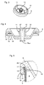
- the filling opening 10 is a through hole and part of a female Luer Lock connection 11, in particular the illustrations in FIG FIGS. 3 and 4 can be seen.
- the filling opening 10 has a circular cross section and is conical, with the diameter decreasing in the direction from the upper to the lower end 6, 5.
- the diameter of the balls 8 is chosen so that it is greater than the minimum diameter d min of the filling opening 10 (FIG. Fig. 4 ), so that the balls 8 do not pass through the filling opening 10 and thus ensures that the balls 8 remain in the closed by the cap 9 cavity 4.
- Luer lock terminal 11 in the usual way an external thread 12 for a stopper 13 (FIG. Fig. 6 ) on.
- the closure cap 9 is firmly connected by means of positive and non-positive connection with the upper end 6 of the main body 2.
- the closure cap 9 has an outer ring 14 (FIG. Fig. 4 ) extending in the state connected to the main body 2 in the longitudinal direction of the main body 2 and having a radially inwardly projecting locking ring 15. Furthermore, the closure cap 9 still has a longitudinally extending annular sealing lip 16.
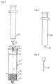
- the desired conditioned blood composition in the container for example, blood taken from a patient (human or animal) is filled into the container 1 by means of a disposable syringe 22 with a disposable cannula 21 ( Fig. 7 ).
- the disposable cannula 21 is introduced through the filling opening 10 into the cavity 4 and then the removed blood is filled from the disposable syringe 22 into the cavity 4.
- the dimensions of the filling opening 10 with respect to the disposable cannula 21 are selected such that between the disposable cannula 21 positioned in the filling opening 10 and the inside 27 (FIG. Fig. 4 ) of the Einhellö Anlagen 10 still a venting gap 23 ( Fig. 7 ) is provided so that air can escape from the cavity 4 during filling of the blood through the vent gap 23.
- the disposable cannula 21 thus does not completely fill the filling opening 10, so that due to the venting gap 23 there is ventilation and thus blood can be filled into the cavity 4 without problems.
- the disposable cannula 21 is pulled out of the filling opening 10. Thereafter, the filling opening 10 by means of the plug 13 ( Fig. 6 ) are closed.
- the stopper 13 is matched to the Luer Lock connection 11 and has an adapted to the external thread 12 internal thread 24 and a Luer cone 25 for sealing the filling opening 10.
- the optionally sealed container 1 can then be centrifuged for example for 10 minutes at 4,500 revolutions / minute. This is preferably carried out at room temperature.
- a storage at room temperature or at a higher temperature of up to 40 ° C and in particular up to 37 ° C of the container 1 can be performed. This storage preferably takes place before centrifuging.
- IL-1Ra interleukin 1 receptor antagonist
- concentration of IL-1 ⁇ is relatively low, so that the ratio of IL-1 ⁇ to IL-1Ra of greater than 1:10, in particular greater than 1: 100 and in particular greater than 1: 250 is achieved. Values of 1: 8800 could be achieved.
- the conditioned blood composition thus prepared can then be used for therapeutic purposes.
- the resulting serum can be removed from the container 1 by unscrewing the stopper 13 (if it was intended) and the serum is removed by means of another disposable syringe 22 with another disposable cannula 21.
- the outer diameter of the other disposable cannula 21 is smaller than the minimum inner diameter of the filling opening 10, so that even when removing the serum of the vent gap 23 and thus a vent is given, which can be removed without problems, the serum from the container 1.
- the serum thus obtained can then be administered to the patient in a known manner. In particular, it can be injected into the joint to be treated, in the area of the nerve root to be treated or elsewhere.
- the container 1 according to the invention can not be provided alone.
- a system for preparing a conditioned blood composition comprising the container 1, the disposable syringe 22 (FIG. Fig. 8 ), the disposable cannula 21 ( Fig. 9 ) and optionally the stopper 13 ( Fig. 6 ) having.
- all elements of the system are individually sterile packed.
- the system may have further elements, in particular more than one disposable cannula 21 may be provided.
- the first disposable needle in conjunction with the disposable syringe 22 may be used to withdraw the blood to the patient.
- the used disposable cannula 21 can be discarded and a further disposable cannula 21 can be connected to the disposable syringe 22 and only then the withdrawn blood can be filled into the container 1. This can be prevented, for example, that a contamination of the first disposable cannula 21 during blood collection (eg by the puncture site) during transfer to the main body 2 is optionally transferred to the blood.
Landscapes
- Health & Medical Sciences (AREA)
- Pharmacology & Pharmacy (AREA)
- Life Sciences & Earth Sciences (AREA)
- Animal Behavior & Ethology (AREA)
- General Health & Medical Sciences (AREA)
- Public Health (AREA)
- Veterinary Medicine (AREA)
- Hematology (AREA)
- Medical Preparation Storing Or Oral Administration Devices (AREA)
Description
- Die vorliegende Erfindung betrifft einen Behälter für die Herstellung einer konditionierten Blutzusammensetzung, die insbesondere IL-1Ra enthält, mit den Merkmalen des Oberbegriffs des Anspruches 1.
- Ein solcher Behälter ist z.B. aus der
DE 10 2008 023 545 A1 bekannt. - Ein Verfahren zur Herstellung von IL-1 Ra in einer Spritze ist beispielsweise aus der
EP 1 151 004 B1 bekannt. Dabei wird einem Patienten (einem Menschen oder einem Tier) mittels einer Spritze Blut entnommen, wobei die Spritze Glaskugeln enthalten kann. Die Spritze mit dem entnommenen Blut wird dann inkubiert, wobei die Inkubation bevorzugt über einen Zeitraum von 12-72 Stunden und vorzugsweise bei einer Temperatur von 20 °C - 41 °C durchgeführt wird. Danach kann die Spritze mit dem darin enthaltenen Blut zentrifugiert werden und das Blutplasma wird mittels einer weiteren Spritze zur weiteren Verwendung entnommen. - Obwohl bis zur Entnahme des Blutplasmas kein Umfüllen des Blutes notwendig ist, ist die Handhabung dennoch aufwendig. Insbesondere muß in der Regel für das Zentrifugieren der aus dem Spritzenzylinder überstehende Teil der Kolbenstange abgebrochen werden. Auch ist ein Verschließen des vorderen Endes der Spritze notwendig, wozu die Spritzenkanüle entfernt und statt dessen ein Verschlußstopfen vorzusehen ist.
- Ausgehend hiervon ist es Aufgabe der Erfindung, einen Behälter der eingangs genannten Art für die Herstellung einer konditionierten Blutzusammensetzung so weiterzubilden, dass eine vereinfachte Handhabung insbesondere bei einem Zentrifugierschritt möglich ist.
- Erfindungsgemäß wird die Aufgabe bei einem Behälter der eingangs genannten Art dadurch gelöst, dass die Abmessungen der Einfüllöffnung so gewählt sind, dass die Teilchen zu groß für die Einfüllöffnung sind und somit nicht durch sie hindurchpassen und dass, wenn das Abgabeende der Spritze zum Einfüllen des Blutes in der Einfüllöffnung positioniert ist, ein Entlüftungsspalt zwischen dem Abgabeende und der Innenseite der Einfüllöffnung vorhanden ist.
- Der Entlüftungsspalt liegt insbesondere auch vor, wenn das Abgabeende der Spritze zum Einfüllen des Blutes in der Einfüllöffnung über die gesamte Länge der Einfüllöffnung oder sogar darüber hinaus bis in den Hohlraum positioniert ist.
- Aufgrund des erfindungsgemäßen Behälters muß lediglich das entnommene Blut in den Behälter eingefüllt werden, was aufgrund des beim Einfüllen vorhandenen Ent- bzw. Belüftungsspaltes ohne Probleme möglich ist. Danach kann der Behälter zusammen mit dem eingefüllten Blut zentrifugiert werden. Somit ist eine einfache Handhabung möglich. Insbesondere müssen keine Kolbenstangen abgebrochen werden und Kanülen durch Verschlußstopfen ersetzt werden.
- Die Einfüllöffnung dient hier somit insbesondere zum Druckausgleich zwischen dem Hohlraum und dem Äußeren (bzw. der Umgebung) und zwar unabhängig davon, ob das Abgabeende in der Einfüllöffnung positioniert ist oder nicht. Aufgrund der Einfüllöffnung ist der Behälter für die einzufüllende Flüssigkeit (z.B. Blut) offen und nicht dicht verschlossen. Für die Teilchen ist der Behälter aufgrund der Abmessungen der Einfüllöffnung jedoch verschlossen bzw. dicht.
- Die Einfüllöffnung ist insbesondere als offenes Durchgangsloch bzw. als offene Durchgangsbohrung ausgebildet.
- Durch die erfindungsgemäße Konstruktion des Behälters und insbesondere der Verschlußkappe müssen z.B. keine Entlüftungsventile in der Verschlußkappe vorgesehen werden, wodurch die Verschlußkappe kostengünstig z.B. als Spritzgußteil hergestellt werden kann. Insbesondere ist die Verschlußkappe bis auf die Einfüllöffnung frei von weiteren Be- bzw. Entlüftungselementen, wie z.B. Ventilen. Auch die Wandung ist bevorzugt frei von weiteren Be- bzw. Entlüftungselementen.
- Unter einer konditionierten Blutzusammensetzung wird hier insbesondere die Blutzusammensetzung verstanden, die man nach dem Zentrifugieren des Behälters mit dem darin enthaltenen Blut erhält. Insbesondere kann es sich um das nach dem Zentrifugieren vorliegende Blutplasma oder -serum handeln.
- Die im Behälter enthaltenen Teilchen dienen im wesentlichen dazu, die dem eingefüllten Blut bereitgestellte Oberfläche zu vergrößern, was sich vorteilhaft bei der Herstellung der konditionierten Blutzusammensetzung erwiesen hat. Insbesondere die Herstellung von IL-1Ra (Interleukin 1-Rezeptor-Antagonist) kann dadurch angeregt oder unterstützt werden. Auch die gewünschte Selektivität im Vergleich zu IL-1β von größer als 10:1 und insbesondere von größer als 100:1 kann dadurch erreicht werden. Natürlich ist der Behälter auch dazu geeignet, zusätzliche oder andere Cytokine, die bevorzugt therapeutisch wirksam sind, zu erzeugen und/oder anzureichern.
- Bei dem erfindungsgemäßen Behälter kann die Wandung als starre Wandung ausgebildet sein. Insbesondere kann der Behälter im wesentlichen hohlzylinderförmig ausgebildet sein.
- Ferner kann die Verschlußkappe die Öffnung so verschließen, daß sie nicht zerstörungsfrei entfernbar ist.
- Die Verschlußkappe kann mittels einer Rastverbindung mit der Wandung verbunden sein. Es ist jedoch auch jede andere Art der Verbindung möglich. Ferner kann eine formschlüssige, kraftschlüssige und/oder stoffschlüssige Verbindung zwischen Verschlußkappe und Wandung vorliegen.
- Die Wandung und die Verschlußkappe sind bevorzugt aus dem gleichen Material hergestellt. Insbesondere wird als Material Kunststoff eingesetzt, wie z.B. Polypropylen, Polystyrol, Polyvinylchlorid oder Polyethylen.
- Natürlich ist es auch möglich, daß die Wandung und die Verschlußkappe aus unterschiedlichen Materialien hergestellt sind. Insbesondere kann die Wandung auch aus einem Glasmaterial hergestellt sein. Die Verschlußkappe ist bevorzugt dann aus einem Kunststoffmaterial hergestellt.
- Bei dem erfindungsgemäßen Behälter kann die Einfüllöffnung Bestandteil eines Luer Lock Anschlusses sein. Damit ist es möglich, herkömmliche Verschlußstopfen einzusetzen, um den Behälter nach dem Befüllen mit dem Blut zu verschließen. Der so verschlossene Behälter kann dann zentrifugiert werden.
- Die in dem Behälter angeordneten Teilchen können im wesentlichen kugelförmig ausgebildet sein. Es ist aber auch jede andere Raumform möglich. Bevorzugt sind die Teilchen gleich groß oder ist sichergestellt, daß sie eine Mindestgröße nicht unterschreiten. Basierend auf der Mindestgröße kann dann durch geeignete Wahl der Abmessungen der Einfüllöffnung sichergestellt werden, daß die Teilchen dauerhaft im Hohlraum eingesperrt sind.
- Die Teilchen können aus Glas oder Kunststoff hergestellt sein. Insbesondere können Sie aus Bor- bzw. Borosilikatglas hergestellt sein.
- In dem Behälter kann ein Antikoagulanzmittel enthalten sein, um die Gerinnung des eingefüllten Blutes zu verhindern. Es ist jedoch auch möglich, daß keinerlei Antikoagulanzmittel im Behälter enthalten ist.
- Der erfindungsgemäße Behälter kann so ausgebildet sein, daß die Wandung nur die eine Öffnung aufweist.
- Bei dem erfindungsgemäßen Behälter kann die Wandung einstückig ausgebildet sein.
- Des weiteren ist der erfindungsgemäße Behälter insbesondere so ausgebildet, daß das Volumen des Hohlraums mit Ausnahme der eingefüllten Teilchen (z.B. Kugeln) und des einzufüllenden Blutes nicht veränderbar bzw. konstant ist. Der erfindungsgemäße Behälter ist also insbesondere keine Spritze, da bei einer Spritze der Hohlraum des Spritzenzylinders durch Bewegung des Kolbens veränderbar ist.
- Der erfindungsgemäße Behälter ist insbesondere frei von bewegbaren Kolben oder einem sonstigen bewegbaren Element, mit dem durch Betätigung von außen das Volumen des Hohlraums wiederholt verkleinert und vergrößert werden kann.
- Ferner kann der Behälter einen Verschlußstopen zum Verschließen der Einfüllöffnung aufweisen.
- Es wird ferner ein System zur Herstellung einer konditionierten Blutzusammensetzung bereitgestellt, das einen erfindungsgemäßen Behälter (einschließlich der erfindungsgemäßen Weiterbildung) sowie eine ein Abgabeende aufweisende Spritze enthält. Das Abgabeende der Spritze ist dabei so ausgebildet, daß ein Entlüftungsspalt zwischen dem Abgabeende und der Innenseite der Einfüllöffnung vorhanden ist, wenn das Abgabeende der Spritze zum Einfüllen von in der Spritze enthaltenem Blut in der Einfüllöffnung positioniert ist (das Abgabeende kann insbesondere so positioniert sein, daß es über die gesamte Länge der Einfüllöffnung in dieser positioniert ist und ggf. darüber hinaus in den Hohlraum einsteht).
- Das Abgabeende der Spritze kann als Kanüle ausgebildet sein, die mit der Spritze verbindbar ist. Insbesondere kann die Spritze als Einmalspritze und die Kanüle als Einmalkanüle ausgebildet sein.
- Bevorzugt sind die einzelnen Elemente des Systems (Behälter, Spritze und ggf. Kanüle) einzeln steril verpackt.
- Das System kann ferner noch den Verschlußstopfen zum Verschließen der Einfüllöffnung aufweisen. Auch der Verschlußstopfen ist bevorzugt einzeln steril verpackt.
- Des weiteren kann das System mehrere Spritzen und/oder mehrere Kanülen aufweisen, die bevorzugt alle jeweils einzeln steril verpackt sind. Bei der Spritze bzw. den Spritzen sowie der Kanüle bzw. den Kanülen handelt es sich bevorzugt um Einwegartikel. Auch der erfindungsgemäße Behälter ist bevorzugt als Einwegartikel ausgebildet.
- Es wird ferner bereitgestellt ein Verfahren zur Herstellung einer konditionierten Blutzusammensetzung, bei dem das Abgabeende einer Spritze, die Blut enthält, in der Einfüllöffnung eines erfindungsgemäßen Behälters so positioniert wird, daß der Entlüftungsspalt vorhanden ist, dann das Blut von der Spritze in den Hohlraum des Behälters eingefüllt wird und danach der Behälter mit dem Blut zentrifugiert wird, um die konditionierte Blutzusammensetzung herzustellen.
- Der Schritt des Zentrifugierens wird bevorzugt bei Raumtemperatur durchgeführt. Insbesondere kann der Zentrifugierschritt bei einer Temperatur im Bereich von 20 °C - 41 °C durchgeführt werden. Die Dauer des Zentrifugierens kann z. B. 10, 15 oder 20 min betragen. Natürlich sind auch längere oder kürzere Zentrifugierzeiten möglich. Eine bevorzugte Zentrifugiergeschwindigkeit beträgt 3500 - 5500 Umdrehungen pro Minute, insbesondere 4500 Umdrehungen pro Minute.
- Ferner kann noch ein Lagerungsschritt (bevorzugt vor dem Zentrifugieren) des Behälters mit dem eingefüllten Blut durchgeführt werden. Auch dieser Lagerungsschritt wird bevorzugt bei Raumtemperatur und insbesondere bei einer Temperatur im Bereich von 20 °C - 41 °C durchgeführt. Die Zeitdauer des Lagerungsschrittes kann vom Minutenbereich bis zum Stundenbereich betragen. So sind Lagerungszeiten von 10-30 min, 30-60 min oder im Bereich von 2 bis 72 Stunden möglich.
- Bei dem erfindungsgemäßen Verfahren kann nach dem Zentrifugierschritt mittels einer Spritze zumindest Teile der im Behälter hergestellten konditionierten Blutzusammensetzung über die Einfüllöffnung entnommen werden. Die Spritze zum Entnehmen weist dabei wiederum ein Abgabeende auf, das so ausgebildet ist, daß ein Entlüftungsspalt vorhanden ist, wenn das Abgabeende in der Einfüllöffnung positioniert ist. Das Abgabeende kann insbesondere wiederum eine Kanüle sein.
- Insbesondere wird das nach dem Zentrifugierschritt vorhandene Blutserum oder -plasma entnommen. Die entnommene konditionierte Blutzusammensetzung, die bevorzugt ein oder mehrere therapeutisch wirksame Cytokine (wie z.B. IL-1 Ra, IL 6, etc.) enthält, kann dann therapeutisch verwendet werden. Insbesondere kann sie demselben Patienten, dem das Blut entnommen wurde, wieder injiziert werden, z.B. an einer Nervenwurzel oder einem Gelenk.
- Ferner kann das erfindungsgemäße Verfahren den Schritt der Blutentnahme aufweisen, wobei bevorzugt die Spritze, mit der das Blut entnommen wird, auch dazu genutzt wird, um das Blut über die Einfüllöffnung in den Behälter einzufüllen. Dabei kann die Spritze unverändert verwendet werden. Es ist jedoch auch möglich, daß die Kanüle zur Blutentnahme von der Spritze entfernt wird und dann eine weitere, sterile Kanüle mit der Spritze verbunden wird, um über diese Kanüle das Blut in den Behälter einzufüllen. Die weitere Kanüle kann auch weggelassen werden, wenn das Abgabeende der Spritze (ohne Kanüle) so ausgebildet ist, daß beim Positionieren des Abgabeendes in der Einfüllöffnung des Behälters der Entlüftungsspalt vorliegt.
- Es versteht sich, daß die vorstehend genannten und die nachstehend noch zu erläuternden Merkmale nicht nur in den angegebenen Kombinationen, sondern auch in anderen Kombinationen oder in Alleinstellung einsetzbar sind, ohne den Rahmen der vorliegenden Erfindung zu verlassen.
- Nachfolgend wird die Erfindung beispielsweise anhand der beigefügten Zeichnungen, die auch erfindungswesentliche Merkmale offenbaren, noch näher erläutert. Es zeigen:
- Fig. 1
- eine perspektivische Ansicht einer Ausführungsform des erfindungsgemäßen Behälters für die Herstellung einer konditionierten Blutzusammensetzung;
- Fig. 2
- eine Schnittansicht des Behälters 1 von
Fig. 1 , wobei die eingefüllten Kugeln 8 nicht in Schnittdarstellung gezeigt sind; - Fig. 3
- eine perspektivische Ansicht der Verschlußkappe 9 des Behälters 1 von
Fig. 1 ; - Fig. 4
- eine Schnittansicht der Verschlußkappe 9 von
Fig. 3 ; - Fig. 5
- eine vergrößerte Ansicht des Details A von
Fig. 2 ; - Fig. 6
- eine Schnittansicht des Verschlußstopfens 13;
- Fig. 7
- eine Ansicht zur Erläuterung des Einfüllens des Blutes von der Spritze 22 in den Behälter 1, wobei die Spritze 22 in Seitenansicht und der Behälter 1 in einer Schnittansicht gemäß
Fig. 2 dargestellt sind; - Fig. 8
- eine Seitenansicht der Spritze 22 von
Fig. 7 , und - Fig. 9
- eine Seitenansicht der Kanüle 21 von
Fig. 7 . - Bei der in
Figuren 1 und 2 gezeigten Ausführungsform umfaßt der erfindungsgemäße Behälter 1 für die Herstellung einer konditionierten Blutzusammensetzung ein im wesentlichen hohlzylinderförmigen Hauptkörper 2 mit kreisförmigem Querschnitt, wobei die Wandung 3 des Hauptkörpers 2 einen Hohlraum 4 (Innenraum des Hauptkörpers 2) begrenzt. - Wie am besten aus
Figur 2 ersichtlich ist, ist das untere Ende 5 des Hauptkörpers 2 verschlossen und das obere Ende 6 offen ausgebildet, so daß der Hauptkörper 2 genau eine Öffnung 7 (am oberen Ende 6) aufweist. Bei dem hier beschriebenen Ausführungsbeispiel ist der Hauptkörper 2 aus Polypropylen hergestellt. - Wie ferner
Figur 2 zu entnehmen ist, sind eine Mehrzahl von Teilchen 8 in den Hohlraum 4 des Hauptkörpers 2 eingefüllt. Die Teilchen können beispielsweise kugelförmig und aus Borsilikatglas hergestellt sein. - Das Gesamtvolumen aller Kugeln 8 kann beispielsweise ca. 1/5 des Volumens des einzufüllenden Blutes aufweisen. Der in
Figur 1 und 2 gezeigte Behälter 1 ist für 50 ml Blut ausgelegt, so daß das Gesamtvolumen der Teilchen 8 ca. 10 ml beträgt. Die Anzahl der Teilchen 8 ergibt sich dann in Abhängigkeit des Kugeldurchmessers. Natürlich kann das Gesamtvolumen aller Teilchen 8 im Verhältnis zu dem Volumen des einzufüllenden Blutes auch größer oder kleiner als 1/5 sein. - Die Öffnung 7 des Hauptkörpers 2 ist mit einer Verschlußkappe 9 verschlossen, der eine Einfüllöffnung 10 aufweist. Die Einfüllöffnung 10 ist ein Durchgangsloch und Bestandteil eines weiblichen Luer Lock Anschlusses 11, wie insbesondere den Darstellungen in
Figuren 3 und 4 zu entnehmen ist. - Die Einfüllöffnung 10 weist einen kreisförmigen Querschnitt auf und ist konisch ausgebildet, wobei der Durchmesser in Richtung vom oberen zum unteren Ende 6,5 hin abnimmt.
- Der Durchmesser der Kugeln 8 ist so gewählt, daß er größer ist als der minimale Durchmesser dmin der Einfüllöffnung 10 (
Fig. 4 ), so daß die Kugeln 8 nicht durch die Einfüllöffnung 10 hindurchpassen und somit sichergestellt ist, daß die Kugeln 8 im durch die Verschlußkappe 9 verschlossenen Hohlraum 4 verbleiben. - Ferner weist der Luer Lock Anschluß 11 noch in üblicher Weise ein Außengewinde 12 für einen Verschlußstopfen 13 (
Fig. 6 ) auf. - Die Verschlußkappe 9 ist mittels Form- und Kraftschluß mit dem oberen Ende 6 des Hauptkörpers 2 fest verbunden. Dazu weist die Verschlußkappe 9 einen Außenring 14 auf (
Fig. 4 ), der sich im mit dem Hauptkörper 2 verbundenen Zustand in Längsrichtung des Hauptkörpers 2 erstreckt und einen radial nach innen vorstehenden Rastring 15 aufweist. Ferner weist die Verschlußkappe 9 noch eine sich in Längsrichtung erstreckende ringförmige Dichtlippe 16 auf. - Wie der vergrößerten Ansicht des Details A von
Figur 2 inFigur 5 zu entnehmen ist, umgreift der Außenring 14 zusammen mit dem Rastring 15 einen am oberen Ende 6 ausgebildeten, ringförmigen Befestigungsabschnitt 17 der Wandung 3, so daß ein sicherer Sitz der Verschlußkappe 9 am Hauptkörper 2 erreicht wird. Um diesen Befestigungszustand zu erreichen, wird die Verschlußkappe 9 von oben auf das obere Ende 6 geschoben, wobei dabei aufgrund des angefasten Abschnitts 18 des Außenrings 14 dieser radial nach außen gedrückt wird, was aufgrund der Elastizität des Materials möglich ist. Sobald die Verschlußkappe 9 soweit über den Befestigungsabschnitt 17 geschoben wurde, daß der Rastring 15 nicht mehr an der nach außen weisenden Seite 19 des Befestigungsabschnitts 17 anliegt, gelangt man aufgrund der Elastizität des Außenrings 14 zu dem inFig. 5 gezeigten Zustand. Gleichzeitig liegt die Dichtlippe 16 an der nach innen weisenden Seite 20 des Befestigungsabschnitts 17 an, so daß am oberen Ende 6 des Hauptkörpers die gewünschte Abdichtung des Hohlraums 4 gegenüber dem Äußeren vorliegt. - Um die gewünschte konditionierte Blutzusammensetzung in dem Behälter 1 herstellen zu können, wird z.B. mittels einer Einmalspritze 22 mit einer Einmalkanüle 21 einem Patienten (Mensch oder Tier) entnommenes Blut in den Behälter 1 eingefüllt (
Fig. 7 ). Dazu wird die Einmalkanüle 21 durch die Einfüllöffnung 10 in den Hohlraum 4 eingeführt und dann das entnommene Blut aus der Einmalspritze 22 in den Hohlraum 4 eingefüllt. - Da der Hauptkörper 2 als starrer bzw. steifer Körper ausgebildet ist, sind die Abmessungen der Einfüllöffnung 10 bezogen auf die Einmalkanüle 21 so gewählt, daß zwischen der in der Einfüllöffnung 10 positionierten Einmalkanüle 21 und der Innenseite 27 (
Fig. 4 ) der Einfüllöffnung 10 noch ein Entlüftungsspalt 23 (Fig. 7 ) vorgesehen ist, so daß Luft aus dem Hohlraum 4 beim Einfüllen des Blutes durch den Entlüftungsspalt 23 austreten kann. Die Einmalkanüle 21 füllt die Einfüllöffnung 10 also nicht vollständig aus, so daß aufgrund des Entlüftungsspaltes 23 eine Belüftung vorliegt und somit ohne Probleme Blut in den Hohlraum 4 eingefüllt werden kann. - Nach dem Einfüllen des Blutes wird die Einmalkanüle 21 aus der Einfüllöffnung 10 herausgezogen. Danach kann die Einfüllöffnung 10 mittels des Verschlußstopfens 13 (
Fig. 6 ) verschlossen werden. Der Verschlußstopfen 13 ist auf den Luer Lock Anschluß 11 abgestimmt und weist ein auf das Außengewinde 12 angepaßtes Innengewinde 24 sowie einen Luer-Konus 25 zur Abdichtung der Einfüllöffnung 10 auf. - Der ggf. verschlossene Behälter 1 kann dann beispielsweise 10 Minuten bei 4.500 Umdrehungen/Minute zentrifugiert werden. Dies wird bevorzugt bei Raumtemperatur durchgeführt. Zusätzlich kann, muß aber nicht, eine Lagerung bei Raumtemperatur oder auch bei einer höheren Temperatur von bis zu 40°C und insbesondere bis zu 37°C des Behälters 1 durchgeführt werden. Diese Lagerung erfolgt bevorzugt vor dem Zentrifugieren.
- Durch diese Schritte wird die gewünschte konditionierte Blutzusammensetzung hergestellt, in der beispielsweise IL-1Ra (Interleukin 1-Rezeptor-Antagonist) angereichert ist. Es können z.B. Konzentrationen von 150-750 pg/ml erzielt werden. Gleichzeitig ist die Konzentration von IL-1 β relativ gering, so daß das Verhältnis von IL-1β zu IL-1Ra von größer als 1:10, insbesondere größer als 1:100 und insbesondere größer als 1:250 erreicht wird. Es konnten Werte von 1:8800 erreicht werden.
- Die so hergestellte konditionierte Blutzusammensetzung kann dann zu therapeutischen Zwecken eingesetzt werden. Insbesondere kann nach der Zentrifugierung das entstandene Serum aus dem Behälter 1 entnommen werden, indem der Verschlußstopfen 13 abgeschraubt wird (sofern er vorgesehen war) und mittels einer weiteren Einmalspritze 22 mit einer weiteren Einmalkanüle 21 das Serum entnommen wird. Auch hier ist wiederum der Außendurchmesser der weiteren Einmalkanüle 21 kleiner als der minimale Innendurchmesser der Einfüllöffnung 10, so daß auch beim Entnehmen des Serums der Entlüftungsspalt 23 und somit eine Entlüftung gegeben ist, wodurch ohne Probleme das Serum aus dem Behälter 1 entnommen werden kann. Das so gewonnene Serum kann dann in bekannter Art und Weise dem Patienten appliziert werden. Insbesondere kann es in das zu behandelnde Gelenk, im Bereich der zu behandelnden Nervenwurzel oder an sonstiger Stelle injiziert werden.
- Der erfindungsgemäße Behälter 1 kann nicht nur alleine bereitgestellt werden. Insbesondere kann ein System zur Herstellung einer konditionierten Blutzusammensetzung bereitgestellt werden, das den Behälter 1, die Einmalspritze 22 (
Fig. 8 ), die Einmalkanüle 21 (Fig. 9 ) und gegebenenfalls den Verschlußstopfen 13 (Fig. 6 ) aufweist. Bevorzugt sind alle Elemente des Systems einzeln steril verpackt. Natürlich kann das System noch weitere Elemente aufweisen, insbesondere können mehr als eine Einmalkanüle 21 vorgesehen sein. So kann beispielsweise die erste Einmalkanüle in Verbindung mit der Einmalspritze 22 verwendet werden, um das Blut dem Patienten zu entnehmen. Nach der Blutentnahme kann die benutzte Einmalkanüle 21 entsorgt und eine weitere Einmalkanüle 21 mit der Einmalspritze 22 verbunden werden und erst danach das entnommene Blut in den Behälter 1 eingefüllt werden. Damit kann z.B. verhindert werden, daß eine Kontamination der ersten Einmalkanüle 21 bei der Blutentnahme (z.B. durch die Einstichstelle) beim Umfüllen in den Hauptkörper 2 auf das Blut gegebenenfalls übertragen wird. - Natürlich ist es auch möglich, beim Einfüllen des Blutes von der Einmalspritze 22 in den Hauptkörper 2 die Einmalkanüle 21 vollständig wegzulassen. In diesem Fall müssen lediglich die Abmessungen der Einfüllöffnung 10 so gewählt sein, daß beim Einführen des vorderen Endes 26 der Einmalspritze 22 (
Fig. 8 ) in die Einfüllöffnung 10 noch der gewünschte Entlüftungsspalt 23 vorliegt.
Claims (15)
- Behälter für die Herstellung einer konditionierten Blutzusammensetzung, die insbesondere IL-1 Ra enthält, mit
einer einen Hohlraum (4) begrenzenden und eine Öffnung (7) aufweisende Wandung (3),
einer Mehrzahl von Teilchen (8), die in den Hohlraum (4) des Behälters (1) eingefüllt sind, und einer die Öffnung (7) verschließenden Verschlußkappe (9), die eine Einfüllöffnung (10) aufweist, in der ein Abgabeende (21, 26) einer Blut enthaltenden Spritze (22) positionierbar ist, um das Blut.der Spritze (22) in den Hohlraum (4) des Behälters (1) einzufüllen,
dadurch gekennzeichnet, dass
die Abmessungen der Einfüllöffnung (10) so gewählt sind, dass die Teilchen (8) zu groß für die Einfüllöffnung (10) sind und somit nicht durch sie hindurchpassen und dass, wenn das Abgabeende (21, 26) der Spritze (22) zum Einfüllen des Blutes in der Einfüllöffnung (10) positioniert ist, ein Entlüftungsspalt (23) zwischen dem Abgabeende (21, 26) und der Innenseite (27) der Einfüllöffnung (10) vorhanden ist. - Behälter nach Anspruch 1, dadurch gekennzeichnet, dass die Wandung (3) als starre Wandung ausgebildet ist.
- Behälter nach Anspruch 1 oder 2, dadurch gekennzeichnet, dass die Verschlußkappe (9) die Öffnung (7) so verschließt, dass die Verschlußkappe (9) nicht zerstörungsfrei entfernbar ist.
- Behälter nach einem der obigen Ansprüche, dadurch gekennzeichnet, dass die Verschlußkappe (9) mittels einer Rastverbindung mit der Wandung (3) verbunden ist.
- Behälter nach einem der obigen Ansprüche, dadurch gekennzeichnet, dass die Wandung (3) und die Verschlußkappe (9) aus dem gleichen Material hergestellt sind.
- Behälter nach einem der obigen Ansprüche, dadurch gekennzeichnet, dass die Einfüllöffnung (10) Bestandteil eines Luer Lock Anschlusses (11) ist.
- Behälter nach einem der obigen Ansprüche, dadurch gekennzeichnet, dass die Teilchen (8) im wesentlichen kugelförmig ausgebildet sind.
- Behälter nach einem der obigen Ansprüche, dadurch gekennzeichnet, dass die Teilchen (8) aus Glas hergestellt sind.
- Behälter nach einem der obigen Ansprüche, dadurch gekennzeichnet, dass die Wandung (3) nur die eine Öffnung (7) aufweist.
- Behälter nach einem der obigen Ansprüche, dadurch gekennzeichnet, dass die Einfüllöffnung (10) als offenes Durchgangsloch ausgebildet ist.
- Behälter nach einem der obigen Ansprüche, dadurch gekennzeichnet, dass der Behälter bis auf die Einfüllöffnung (10) frei ist von weiteren Be- bzw. Entlüftungselementen.
- Behälter nach einem der obigen Ansprüche, dadurch gekennzeichnet, dass Behälter aufgrund der Einfüllöffnung (10) für das einzufüllende Blut offen und für die Teilchen (8) geschlossen ist.
- Behälter nach einem der obigen Ansprüche, dadurch gekennzeichnet, dass das Volumen des Hohlraums außer mit den eingefüllten Teilchen und dem einzufüllenden Blut nicht veränderbar ist.
- System zur Herstellung einer konditionierten Blutzusammensetzung, die insbesondere IL-1Ra enthält, mit
einer ein Abgabeende (21, 26) aufweisenden Spritze (22),
gekennzeichnet durch einen Behälter (1) nach einem der obigen Ansprüche,
wobei der Entlüftungsspalt (23) zwischen dem Abgabeende (21, 26) und der Innseite (27) der Einfüllöffnung (10) vorhanden ist, wenn das Abgabeende (21, 26) der Spritze (22) zum Einfüllen von in der Spritze (22) enthaltenem Blut in der Einfüllöffnung (10) positioniert ist. - Verfahren zur Herstellung einer konditionierten Blutzusammensetzung, die insbesondere IL-1Ra enthält, dadurch gekennzeichnet, dass
das Abgabeende (21, 26) einer Spritze (22), die Blut enthält, in der Einfüllöffnung (10) eines Behälters (1) nach einem der Ansprüche 1 bis 13 so positioniert wird, dass der Entlüftungsspalt (23) vorhanden ist, dann das Blut von der Spritze (22) in den Hohlraum (4) des Behälters (1) eingefüllt wird,
und bei dem der Behälter mit dem Blut zentrifugiert wird, um die konditionierte Blutzusammensetzung herzustellen.
Applications Claiming Priority (1)
| Application Number | Priority Date | Filing Date | Title |
|---|---|---|---|
| DE201010042356 DE102010042356A1 (de) | 2010-10-12 | 2010-10-12 | Behälter für die Herstellung einer konditionierten Blutzusammensetzung |
Publications (3)
| Publication Number | Publication Date |
|---|---|
| EP2441431A2 EP2441431A2 (de) | 2012-04-18 |
| EP2441431A3 EP2441431A3 (de) | 2013-11-06 |
| EP2441431B1 true EP2441431B1 (de) | 2016-04-13 |
Family
ID=45390028
Family Applications (1)
| Application Number | Title | Priority Date | Filing Date |
|---|---|---|---|
| EP11176691.1A Active EP2441431B1 (de) | 2010-10-12 | 2011-08-05 | Behälter für die Herstellung einer konditionierten Blutzusammensetzung |
Country Status (4)
| Country | Link |
|---|---|
| EP (1) | EP2441431B1 (de) |
| DE (1) | DE102010042356A1 (de) |
| ES (1) | ES2578510T3 (de) |
| PL (1) | PL2441431T3 (de) |
Families Citing this family (1)
| Publication number | Priority date | Publication date | Assignee | Title |
|---|---|---|---|---|
| US9241977B2 (en) * | 2013-03-01 | 2016-01-26 | Arthrex, Inc. | Enhanced anabolic cytokine production and delivery system |
Family Cites Families (6)
| Publication number | Priority date | Publication date | Assignee | Title |
|---|---|---|---|---|
| US3630199A (en) * | 1970-05-26 | 1971-12-28 | Louis P Gangarosa | Unitized injection system |
| US3729032A (en) * | 1971-12-06 | 1973-04-24 | Mpl Inc | Liquid dispenser and method and apparatus for filling same |
| DE19903876B4 (de) | 1999-02-01 | 2006-09-28 | Orthogen Gentechnologie Gmbh | Verfahren zur in-vitro-Bildung und Anreicherung von Interleukin-1 Rezeptor-Antagonisten |
| DE102006005016A1 (de) * | 2006-02-03 | 2007-08-16 | Orthogen Ag | Konditionierte Blutzusammensetzung und Verfahren zu deren Herstellung |
| DE102008023545A1 (de) * | 2008-05-14 | 2009-11-19 | Roderfeld Und Bora Gmbh & Co.Kg | Vorrichtung zur Herstellung einer biologisch aktiven Substanz |
| DE102008036282A1 (de) * | 2008-08-04 | 2010-02-11 | Bimed Teknik A.S., Büyükcekmece | Flüssigkeitsdichter Behälter zur Aufnahme einer zuvor entnommenen Körperflüssigkeit und Verfahren zum Sterilisieren eines solchen Behälters |
-
2010
- 2010-10-12 DE DE201010042356 patent/DE102010042356A1/de not_active Withdrawn
-
2011
- 2011-08-05 EP EP11176691.1A patent/EP2441431B1/de active Active
- 2011-08-05 ES ES11176691.1T patent/ES2578510T3/es active Active
- 2011-08-05 PL PL11176691.1T patent/PL2441431T3/pl unknown
Also Published As
| Publication number | Publication date |
|---|---|
| PL2441431T3 (pl) | 2016-10-31 |
| ES2578510T3 (es) | 2016-07-27 |
| DE102010042356A1 (de) | 2012-04-12 |
| EP2441431A2 (de) | 2012-04-18 |
| EP2441431A3 (de) | 2013-11-06 |
Similar Documents
| Publication | Publication Date | Title |
|---|---|---|
| DE3885018T2 (de) | Injektionsspritze. | |
| DE3875980T2 (de) | Vorgefuellte injektionsspritze. | |
| EP3106188B1 (de) | Verfahren zur montage einer sicherheitsvorrichtung auf einem spritzenkörper | |
| DE2854527A1 (de) | Injektionsspritze | |
| EP1917055A2 (de) | Doppelkammer-behälter ohne bypass | |
| EP2435111B1 (de) | Zweikammer zylinder-kolben-einheit zur lyophilisation, lagerung, rekonstitution und applikation von injektionslösungen für einen injektor und verfahren zum befüllen der zylinder-kolben-einheit | |
| DE1296312B (de) | Zweikammerbehaelter zum getrennten Abfuellen und Aufbewahren von Medikamenten und Loesungen bzw. Verduennungsmitteln in einer zur spaeteren Vermischung und darauffolgenden Entnahme geeigneten Form | |
| DE2259825A1 (de) | Injektionsspritze | |
| WO2000007647A1 (de) | Fertig-spritze für nicht-stabile arzneimittel | |
| EP1484072A1 (de) | Spritze sowie Verfahren zum Herstellen einer solchen | |
| WO2009098164A9 (de) | System zur injektion eines fluids durch oder in die menschliche haut | |
| EP1064961A1 (de) | Spritze für medizinische Zwecke | |
| EP3129146A2 (de) | Aufnahmebehälter sowie aufnahmeeinheit zur aufnahme von körperflüssigkeit | |
| DE102016118767B4 (de) | Verfahren zum Herstellen einer Spritze mit einem integrierten Verschlusselement | |
| EP2441431A2 (de) | Behälter für die Herstellung einer konditionierten Blutzusammensetzung | |
| EP3530304A1 (de) | Kanüle für intravitreale punktion und injektion | |
| EP1154812B1 (de) | Spritzeneinrichtung | |
| AT519610B1 (de) | System und Verfahren zur sterilen Abnahme von Körperflüssigkeit | |
| DE202010005982U1 (de) | Zylinder-Kolben-Einheit mit einem rohrförmigen Austrittselement | |
| WO2018010914A1 (de) | Misch- und austragsystem für knochenersatzmaterial | |
| WO2023222512A1 (de) | Wirkstoffampulle für eine medizinische spritze und verfahren zum befüllen einer solchen wirkstoffampulle | |
| DE102008025012A1 (de) | Nadeleinheit mit Drehanschlag | |
| EP4491208A1 (de) | Medizinische spritze und nadelaufsatz für eine solche spritze | |
| CH699472A2 (de) | Spritze, insbesondere für Medikamente mit speziellem Luer-Konus (Nadelaufsatz) mit Spitze. | |
| DE102008025022A1 (de) | Nadeleinheit mit sich veränderndem Fluidführungsquerschnitt |
Legal Events
| Date | Code | Title | Description |
|---|---|---|---|
| PUAI | Public reference made under article 153(3) epc to a published international application that has entered the european phase |
Free format text: ORIGINAL CODE: 0009012 |
|
| AK | Designated contracting states |
Kind code of ref document: A2 Designated state(s): AL AT BE BG CH CY CZ DE DK EE ES FI FR GB GR HR HU IE IS IT LI LT LU LV MC MK MT NL NO PL PT RO RS SE SI SK SM TR |
|
| AX | Request for extension of the european patent |
Extension state: BA ME |
|
| PUAL | Search report despatched |
Free format text: ORIGINAL CODE: 0009013 |
|
| AK | Designated contracting states |
Kind code of ref document: A3 Designated state(s): AL AT BE BG CH CY CZ DE DK EE ES FI FR GB GR HR HU IE IS IT LI LT LU LV MC MK MT NL NO PL PT RO RS SE SI SK SM TR |
|
| AX | Request for extension of the european patent |
Extension state: BA ME |
|
| RIC1 | Information provided on ipc code assigned before grant |
Ipc: A61J 1/14 20060101ALN20131001BHEP Ipc: A61J 1/20 20060101AFI20131001BHEP Ipc: A61J 1/06 20060101ALI20131001BHEP |
|
| 17P | Request for examination filed |
Effective date: 20140321 |
|
| RBV | Designated contracting states (corrected) |
Designated state(s): AL AT BE BG CH CY CZ DE DK EE ES FI FR GB GR HR HU IE IS IT LI LT LU LV MC MK MT NL NO PL PT RO RS SE SI SK SM TR |
|
| REG | Reference to a national code |
Ref country code: DE Ref legal event code: R079 Ref document number: 502011009412 Country of ref document: DE Free format text: PREVIOUS MAIN CLASS: A61J0001050000 Ipc: A61J0001200000 |
|
| RIC1 | Information provided on ipc code assigned before grant |
Ipc: A61J 1/06 20060101ALI20151023BHEP Ipc: A61J 1/14 20060101ALN20151023BHEP Ipc: A61J 1/20 20060101AFI20151023BHEP |
|
| GRAP | Despatch of communication of intention to grant a patent |
Free format text: ORIGINAL CODE: EPIDOSNIGR1 |
|
| INTG | Intention to grant announced |
Effective date: 20151215 |
|
| GRAS | Grant fee paid |
Free format text: ORIGINAL CODE: EPIDOSNIGR3 |
|
| GRAA | (expected) grant |
Free format text: ORIGINAL CODE: 0009210 |
|
| AK | Designated contracting states |
Kind code of ref document: B1 Designated state(s): AL AT BE BG CH CY CZ DE DK EE ES FI FR GB GR HR HU IE IS IT LI LT LU LV MC MK MT NL NO PL PT RO RS SE SI SK SM TR |
|
| REG | Reference to a national code |
Ref country code: GB Ref legal event code: FG4D Free format text: NOT ENGLISH |
|
| REG | Reference to a national code |
Ref country code: AT Ref legal event code: REF Ref document number: 789297 Country of ref document: AT Kind code of ref document: T Effective date: 20160415 Ref country code: CH Ref legal event code: EP |
|
| REG | Reference to a national code |
Ref country code: CH Ref legal event code: NV Representative=s name: KELLER AND PARTNER PATENTANWAELTE AG, CH |
|
| REG | Reference to a national code |
Ref country code: IE Ref legal event code: FG4D Free format text: LANGUAGE OF EP DOCUMENT: GERMAN |
|
| REG | Reference to a national code |
Ref country code: DE Ref legal event code: R096 Ref document number: 502011009412 Country of ref document: DE |
|
| REG | Reference to a national code |
Ref country code: ES Ref legal event code: FG2A Ref document number: 2578510 Country of ref document: ES Kind code of ref document: T3 Effective date: 20160727 |
|
| REG | Reference to a national code |
Ref country code: LT Ref legal event code: MG4D |
|
| REG | Reference to a national code |
Ref country code: FR Ref legal event code: PLFP Year of fee payment: 6 |
|
| REG | Reference to a national code |
Ref country code: NL Ref legal event code: MP Effective date: 20160413 |
|
| PG25 | Lapsed in a contracting state [announced via postgrant information from national office to epo] |
Ref country code: FI Free format text: LAPSE BECAUSE OF FAILURE TO SUBMIT A TRANSLATION OF THE DESCRIPTION OR TO PAY THE FEE WITHIN THE PRESCRIBED TIME-LIMIT Effective date: 20160413 Ref country code: NL Free format text: LAPSE BECAUSE OF FAILURE TO SUBMIT A TRANSLATION OF THE DESCRIPTION OR TO PAY THE FEE WITHIN THE PRESCRIBED TIME-LIMIT Effective date: 20160413 Ref country code: NO Free format text: LAPSE BECAUSE OF FAILURE TO SUBMIT A TRANSLATION OF THE DESCRIPTION OR TO PAY THE FEE WITHIN THE PRESCRIBED TIME-LIMIT Effective date: 20160713 Ref country code: LT Free format text: LAPSE BECAUSE OF FAILURE TO SUBMIT A TRANSLATION OF THE DESCRIPTION OR TO PAY THE FEE WITHIN THE PRESCRIBED TIME-LIMIT Effective date: 20160413 |
|
| PG25 | Lapsed in a contracting state [announced via postgrant information from national office to epo] |
Ref country code: LV Free format text: LAPSE BECAUSE OF FAILURE TO SUBMIT A TRANSLATION OF THE DESCRIPTION OR TO PAY THE FEE WITHIN THE PRESCRIBED TIME-LIMIT Effective date: 20160413 Ref country code: PT Free format text: LAPSE BECAUSE OF FAILURE TO SUBMIT A TRANSLATION OF THE DESCRIPTION OR TO PAY THE FEE WITHIN THE PRESCRIBED TIME-LIMIT Effective date: 20160816 Ref country code: GR Free format text: LAPSE BECAUSE OF FAILURE TO SUBMIT A TRANSLATION OF THE DESCRIPTION OR TO PAY THE FEE WITHIN THE PRESCRIBED TIME-LIMIT Effective date: 20160714 Ref country code: RS Free format text: LAPSE BECAUSE OF FAILURE TO SUBMIT A TRANSLATION OF THE DESCRIPTION OR TO PAY THE FEE WITHIN THE PRESCRIBED TIME-LIMIT Effective date: 20160413 Ref country code: SE Free format text: LAPSE BECAUSE OF FAILURE TO SUBMIT A TRANSLATION OF THE DESCRIPTION OR TO PAY THE FEE WITHIN THE PRESCRIBED TIME-LIMIT Effective date: 20160413 Ref country code: HR Free format text: LAPSE BECAUSE OF FAILURE TO SUBMIT A TRANSLATION OF THE DESCRIPTION OR TO PAY THE FEE WITHIN THE PRESCRIBED TIME-LIMIT Effective date: 20160413 |
|
| PG25 | Lapsed in a contracting state [announced via postgrant information from national office to epo] |
Ref country code: BE Free format text: LAPSE BECAUSE OF NON-PAYMENT OF DUE FEES Effective date: 20160831 |
|
| REG | Reference to a national code |
Ref country code: DE Ref legal event code: R097 Ref document number: 502011009412 Country of ref document: DE |
|
| PG25 | Lapsed in a contracting state [announced via postgrant information from national office to epo] |
Ref country code: SK Free format text: LAPSE BECAUSE OF FAILURE TO SUBMIT A TRANSLATION OF THE DESCRIPTION OR TO PAY THE FEE WITHIN THE PRESCRIBED TIME-LIMIT Effective date: 20160413 Ref country code: EE Free format text: LAPSE BECAUSE OF FAILURE TO SUBMIT A TRANSLATION OF THE DESCRIPTION OR TO PAY THE FEE WITHIN THE PRESCRIBED TIME-LIMIT Effective date: 20160413 Ref country code: DK Free format text: LAPSE BECAUSE OF FAILURE TO SUBMIT A TRANSLATION OF THE DESCRIPTION OR TO PAY THE FEE WITHIN THE PRESCRIBED TIME-LIMIT Effective date: 20160413 Ref country code: CZ Free format text: LAPSE BECAUSE OF FAILURE TO SUBMIT A TRANSLATION OF THE DESCRIPTION OR TO PAY THE FEE WITHIN THE PRESCRIBED TIME-LIMIT Effective date: 20160413 Ref country code: RO Free format text: LAPSE BECAUSE OF FAILURE TO SUBMIT A TRANSLATION OF THE DESCRIPTION OR TO PAY THE FEE WITHIN THE PRESCRIBED TIME-LIMIT Effective date: 20160413 |
|
| PLBE | No opposition filed within time limit |
Free format text: ORIGINAL CODE: 0009261 |
|
| STAA | Information on the status of an ep patent application or granted ep patent |
Free format text: STATUS: NO OPPOSITION FILED WITHIN TIME LIMIT |
|
| PG25 | Lapsed in a contracting state [announced via postgrant information from national office to epo] |
Ref country code: SM Free format text: LAPSE BECAUSE OF FAILURE TO SUBMIT A TRANSLATION OF THE DESCRIPTION OR TO PAY THE FEE WITHIN THE PRESCRIBED TIME-LIMIT Effective date: 20160413 |
|
| 26N | No opposition filed |
Effective date: 20170116 |
|
| PG25 | Lapsed in a contracting state [announced via postgrant information from national office to epo] |
Ref country code: MC Free format text: LAPSE BECAUSE OF FAILURE TO SUBMIT A TRANSLATION OF THE DESCRIPTION OR TO PAY THE FEE WITHIN THE PRESCRIBED TIME-LIMIT Effective date: 20160413 |
|
| PG25 | Lapsed in a contracting state [announced via postgrant information from national office to epo] |
Ref country code: SI Free format text: LAPSE BECAUSE OF FAILURE TO SUBMIT A TRANSLATION OF THE DESCRIPTION OR TO PAY THE FEE WITHIN THE PRESCRIBED TIME-LIMIT Effective date: 20160413 |
|
| REG | Reference to a national code |
Ref country code: IE Ref legal event code: MM4A |
|
| PG25 | Lapsed in a contracting state [announced via postgrant information from national office to epo] |
Ref country code: IE Free format text: LAPSE BECAUSE OF NON-PAYMENT OF DUE FEES Effective date: 20160805 |
|
| REG | Reference to a national code |
Ref country code: FR Ref legal event code: PLFP Year of fee payment: 7 |
|
| PG25 | Lapsed in a contracting state [announced via postgrant information from national office to epo] |
Ref country code: LU Free format text: LAPSE BECAUSE OF NON-PAYMENT OF DUE FEES Effective date: 20160805 |
|
| PG25 | Lapsed in a contracting state [announced via postgrant information from national office to epo] |
Ref country code: HU Free format text: LAPSE BECAUSE OF FAILURE TO SUBMIT A TRANSLATION OF THE DESCRIPTION OR TO PAY THE FEE WITHIN THE PRESCRIBED TIME-LIMIT; INVALID AB INITIO Effective date: 20110805 Ref country code: CY Free format text: LAPSE BECAUSE OF FAILURE TO SUBMIT A TRANSLATION OF THE DESCRIPTION OR TO PAY THE FEE WITHIN THE PRESCRIBED TIME-LIMIT Effective date: 20160413 |
|
| PG25 | Lapsed in a contracting state [announced via postgrant information from national office to epo] |
Ref country code: MK Free format text: LAPSE BECAUSE OF FAILURE TO SUBMIT A TRANSLATION OF THE DESCRIPTION OR TO PAY THE FEE WITHIN THE PRESCRIBED TIME-LIMIT Effective date: 20160413 Ref country code: IS Free format text: LAPSE BECAUSE OF FAILURE TO SUBMIT A TRANSLATION OF THE DESCRIPTION OR TO PAY THE FEE WITHIN THE PRESCRIBED TIME-LIMIT Effective date: 20160413 Ref country code: MT Free format text: LAPSE BECAUSE OF FAILURE TO SUBMIT A TRANSLATION OF THE DESCRIPTION OR TO PAY THE FEE WITHIN THE PRESCRIBED TIME-LIMIT Effective date: 20160413 |
|
| PG25 | Lapsed in a contracting state [announced via postgrant information from national office to epo] |
Ref country code: BG Free format text: LAPSE BECAUSE OF FAILURE TO SUBMIT A TRANSLATION OF THE DESCRIPTION OR TO PAY THE FEE WITHIN THE PRESCRIBED TIME-LIMIT Effective date: 20160413 |
|
| REG | Reference to a national code |
Ref country code: FR Ref legal event code: PLFP Year of fee payment: 8 |
|
| PG25 | Lapsed in a contracting state [announced via postgrant information from national office to epo] |
Ref country code: AL Free format text: LAPSE BECAUSE OF FAILURE TO SUBMIT A TRANSLATION OF THE DESCRIPTION OR TO PAY THE FEE WITHIN THE PRESCRIBED TIME-LIMIT Effective date: 20160413 |
|
| REG | Reference to a national code |
Ref country code: CH Ref legal event code: PFA Owner name: HENKE-SASS, WOLF GMBH, DE Free format text: FORMER OWNER: HENKE-SASS, WOLF GMBH, DE |
|
| PGFP | Annual fee paid to national office [announced via postgrant information from national office to epo] |
Ref country code: TR Payment date: 20220802 Year of fee payment: 12 Ref country code: IT Payment date: 20220831 Year of fee payment: 12 Ref country code: GB Payment date: 20220824 Year of fee payment: 12 Ref country code: ES Payment date: 20220919 Year of fee payment: 12 Ref country code: DE Payment date: 20220822 Year of fee payment: 12 Ref country code: AT Payment date: 20220818 Year of fee payment: 12 |
|
| PGFP | Annual fee paid to national office [announced via postgrant information from national office to epo] |
Ref country code: PL Payment date: 20220725 Year of fee payment: 12 Ref country code: FR Payment date: 20220822 Year of fee payment: 12 |
|
| PGFP | Annual fee paid to national office [announced via postgrant information from national office to epo] |
Ref country code: CH Payment date: 20220824 Year of fee payment: 12 |
|
| REG | Reference to a national code |
Ref country code: DE Ref legal event code: R119 Ref document number: 502011009412 Country of ref document: DE |
|
| REG | Reference to a national code |
Ref country code: CH Ref legal event code: PL |
|
| REG | Reference to a national code |
Ref country code: AT Ref legal event code: MM01 Ref document number: 789297 Country of ref document: AT Kind code of ref document: T Effective date: 20230805 |
|
| PG25 | Lapsed in a contracting state [announced via postgrant information from national office to epo] |
Ref country code: AT Free format text: LAPSE BECAUSE OF NON-PAYMENT OF DUE FEES Effective date: 20230805 |
|
| GBPC | Gb: european patent ceased through non-payment of renewal fee |
Effective date: 20230805 |
|
| PG25 | Lapsed in a contracting state [announced via postgrant information from national office to epo] |
Ref country code: AT Free format text: LAPSE BECAUSE OF NON-PAYMENT OF DUE FEES Effective date: 20230805 Ref country code: CH Free format text: LAPSE BECAUSE OF NON-PAYMENT OF DUE FEES Effective date: 20230831 |
|
| PG25 | Lapsed in a contracting state [announced via postgrant information from national office to epo] |
Ref country code: GB Free format text: LAPSE BECAUSE OF NON-PAYMENT OF DUE FEES Effective date: 20230805 |
|
| PG25 | Lapsed in a contracting state [announced via postgrant information from national office to epo] |
Ref country code: IT Free format text: LAPSE BECAUSE OF NON-PAYMENT OF DUE FEES Effective date: 20230805 Ref country code: GB Free format text: LAPSE BECAUSE OF NON-PAYMENT OF DUE FEES Effective date: 20230805 Ref country code: FR Free format text: LAPSE BECAUSE OF NON-PAYMENT OF DUE FEES Effective date: 20230831 Ref country code: DE Free format text: LAPSE BECAUSE OF NON-PAYMENT OF DUE FEES Effective date: 20240301 |
|
| REG | Reference to a national code |
Ref country code: ES Ref legal event code: FD2A Effective date: 20240927 |
|
| PG25 | Lapsed in a contracting state [announced via postgrant information from national office to epo] |
Ref country code: ES Free format text: LAPSE BECAUSE OF NON-PAYMENT OF DUE FEES Effective date: 20230806 |
|
| PG25 | Lapsed in a contracting state [announced via postgrant information from national office to epo] |
Ref country code: PL Free format text: LAPSE BECAUSE OF NON-PAYMENT OF DUE FEES Effective date: 20230805 |
|
| PG25 | Lapsed in a contracting state [announced via postgrant information from national office to epo] |
Ref country code: PL Free format text: LAPSE BECAUSE OF NON-PAYMENT OF DUE FEES Effective date: 20230805 Ref country code: ES Free format text: LAPSE BECAUSE OF NON-PAYMENT OF DUE FEES Effective date: 20230806 |
|
| PG25 | Lapsed in a contracting state [announced via postgrant information from national office to epo] |
Ref country code: TR Free format text: LAPSE BECAUSE OF NON-PAYMENT OF DUE FEES Effective date: 20230805 |