EP2440795B1 - Famille de dispositifs de fixation à conicité variable - Google Patents
Famille de dispositifs de fixation à conicité variable Download PDFInfo
- Publication number
- EP2440795B1 EP2440795B1 EP10737959.6A EP10737959A EP2440795B1 EP 2440795 B1 EP2440795 B1 EP 2440795B1 EP 10737959 A EP10737959 A EP 10737959A EP 2440795 B1 EP2440795 B1 EP 2440795B1
- Authority
- EP
- European Patent Office
- Prior art keywords
- interference
- bushing
- taper
- family according
- screw
- Prior art date
- Legal status (The legal status is an assumption and is not a legal conclusion. Google has not performed a legal analysis and makes no representation as to the accuracy of the status listed.)
- Active
Links
Images
Classifications
-
- F—MECHANICAL ENGINEERING; LIGHTING; HEATING; WEAPONS; BLASTING
- F16—ENGINEERING ELEMENTS AND UNITS; GENERAL MEASURES FOR PRODUCING AND MAINTAINING EFFECTIVE FUNCTIONING OF MACHINES OR INSTALLATIONS; THERMAL INSULATION IN GENERAL
- F16B—DEVICES FOR FASTENING OR SECURING CONSTRUCTIONAL ELEMENTS OR MACHINE PARTS TOGETHER, e.g. NAILS, BOLTS, CIRCLIPS, CLAMPS, CLIPS OR WEDGES; JOINTS OR JOINTING
- F16B5/00—Joining sheets or plates, e.g. panels, to one another or to strips or bars parallel to them
- F16B5/02—Joining sheets or plates, e.g. panels, to one another or to strips or bars parallel to them by means of fastening members using screw-thread
-
- F—MECHANICAL ENGINEERING; LIGHTING; HEATING; WEAPONS; BLASTING
- F16—ENGINEERING ELEMENTS AND UNITS; GENERAL MEASURES FOR PRODUCING AND MAINTAINING EFFECTIVE FUNCTIONING OF MACHINES OR INSTALLATIONS; THERMAL INSULATION IN GENERAL
- F16B—DEVICES FOR FASTENING OR SECURING CONSTRUCTIONAL ELEMENTS OR MACHINE PARTS TOGETHER, e.g. NAILS, BOLTS, CIRCLIPS, CLAMPS, CLIPS OR WEDGES; JOINTS OR JOINTING
- F16B3/00—Key-type connections; Keys
- F16B3/06—Key-type connections; Keys using taper sleeves
Definitions
- the present invention relates to a family of variable taper fasteners.
- the technical field of the invention is, in general, that of screws and sockets. More particularly, the invention relates to screws and bushings for assembling aircraft structural elements pre-bored in a cylindrical manner.
- cylindrical and / or frustoconical screws made of metallic material and coated with a coating promoting their sliding within a metal are known. bore of elements to be assembled.
- US4048898 , US4702658 , and US3270410 discloses, respectively, a frustoconical device for fixing multilayer metal elements, a device for reducing forces and installation costs of a frustoconical fixing device and a fastening method for installing prestressing in a material.
- the conical barrel fasteners are usually used by aircraft manufacturers in the areas to be assembled which have accessibility difficulties and require interference.
- the interference is defined by the installation of a screw having a smooth portion which has an outside diameter greater than the bore diameter which will receive it, which causes an expansion of the bore during the installation of the screw.
- the installation of the interference screws is done simply by pulling them or by pushing them into the bore which by means of an optimized design of the input radius of the barrel of the screw and a coating to low coefficient of friction does not cause damage to the structure.
- the interference installation increases the fatigue life of the structure.
- the new generation of aircraft uses a composite material structure that has the advantage of significantly lightening the aircraft and is not sensitive to the phenomenon of fatigue but, unlike a metal structure, has the disadvantage of a poor conductivity and poses problems of resistance to the impacts of lightning. In order to resist the lightning, it is also necessary to fill any gap that exists between the fixing and the bore thus imposing an interference installation in the composites.
- the invention can also have applications in mixed structures that is to say using composite and metal materials such as aluminum alloy or titanium for example, the device will be installed in a series of metal / composite layers that form the aircraft structure; or also in only metal structures of the aluminum or titanium type for example, in this case there will be no risk of delamination but the advantage of the use of the invention lies in the fact of the elimination of holes conical.
- the taper ratio of the sleeves according to the invention is between a few tenths of a percent and 10%.
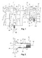
- the figure 1 schematically represents a sectional view of a first example of a family of element fixing devices, according to the invention.
- the elements to be assembled constitute an aircraft structure and the family comprises two fastening devices 1 and 20.
- the device 1 is shown on the left side A1 of its axis of symmetry 5 passing through it in the middle, before interference, that is to say at the very beginning of the installation, when it has been inserted without effort, with play. and without radial expansion, in the structure of the aircraft.
- the device is shown after interference by radial expansion in the structure, the right side B1 of the axis 5, the cutting plane being defined by this axis 5.
- the device 20 is shown before interference, the left side A20 of its axis of symmetry 24 passing through it in the middle.
- the device is shown, after interference, on the right side B20 of the axis 24, the section plane being defined by this axis 24.
- the fixing device 1 is intended to assemble four previously bored cylindrical structural elements 40, 41, 42 and 43, with a diameter 18.
- the elements 40, 41, 42 and 43 to assemble have an overall thickness referenced 12.
- the device 1 comprises a screw 4 extending along the axis 5.
- the screw 4 comprises a frustoconical barrel 6 extending on one side in a flat cylindrical head 7 and, on the other hand, in a thread 17.
- the head 7 forms a disk whose plane is perpendicular to the axis 5, the disk being intended to be disposed substantially parallel to an upper surface 13 of the element.
- the device 1 also comprises a bushing 8 intended to receive the frustoconical drum 6 of the screw 4 therein.
- the bushing 8 extends along the same axis 5 and has a cylindrical outer surface 9 and a frustoconical inner surface 10.
- a distance, called protrusion P1 separates, before interference, a lower surface 14 of the screw head 7 and an upper surface 15 of the bushing 8.
- an initial clearance J1 mounting between an outer diameter 16A of the sleeve 8 before interference and the bore diameter 18 of the elements 40, 41 , 42 and 43 is provided.
- the initial clearance and the expansion are controlled by pre-machining in the factory, the external diameter with a precision of the order of a few tens of microns, the bushing with its pre-screw -managed to protrusion P1, itself also controlled in the factory.
- the fixing device 20 is intended to assemble two previously bored cylindrical structural elements 44 and 45 with the same diameter 18.
- the elements to be assembled comprise two layers 44 and 45 whose overall thickness is referenced 31.
- the device 20 comprises a screw 23 extending along the axis 24.
- the screw 23 comprises a frustoconical barrel 25 extending on one side into a flat cylindrical head 26 and, on the other side, into a thread 39
- the head 26 forms a disk whose plane is perpendicular to the axis 24, the disk being intended to be disposed substantially parallel to an upper surface 32 of the element 44.
- the device 20 also comprises a sleeve 27 intended to receive the frustoconical barrel 25 of the screw 23 therein.
- the sleeve 27 extends along the same axis 24 and has a cylindrical outer surface 28 and a frustoconical inner surface 29.
- a protrusion P2 separates, before interference, a lower surface 33 of the screw head 23 and an upper surface 34 of the sleeve 27.
- the screws 4 and 23 are driven by pulling via a nut screwed around the thread 17 or with the aid of a pulling chuck or pushing on the head.
- an interference is made between the screw, the socket and the element to be assembled, over the entire thickness.
- This interference corresponds to a difference IF1 and IF2 between a diameter 18 of the bore and an outside diameter 16B and 16D of the sleeve after interference.
- the interference is chosen and predetermined to at least offset the initial clearance, i.e fill the empty space, exerting a radial pressure on the element to be assembled, and thus pre-constrain the assembly radially.
- the two devices 1 and 20 thus comprise sockets 8 and 27 having, before interference, an outer diameter 16A and 16C identical and a C1 and C2 rate of conicity of different inner surface. More precisely, the taper ratio formed by the axis 5 and 24 and the frustoconical surface 10 and 29 of the sockets 8 and 27, respectively, varies inversely with the height 19 and 30 of the sockets 8 and 27 respectively.
- the conicity rate is between a few tenths of a percent and 10%, preferably between 1% and 4%.
- the taper ratio of the barrel 6 and 25 of the screw 4 and 23 is the same as that of the inner surface 10 and 29 of the bushing 8 and 27, respectively.
- the taper ratio of the barrel 6 and 25 of the screw 4 and 23 may be substantially different from the inner surface 10 and 29. the bushing 8 and 27 to generate variable interference, controlled, along the thickness.
- the conicity rate may vary locally within the same subfamily so as to adjust the interference in a defined area.
- the height 19 and 30 of the sleeves 8 and 27 corresponds, at least, to their outer diameter after interference 16B and 16D and, at most, to ten times this diameter.
- the degree of conicity of the bushing 8 is here equal to the ratio, in percentage, of the difference between its largest diameter D8 and its smaller diameter d8 of its frustoconical inner surface 10 by its height 19.
- C8 (D8 - d8) / 19.
- the taper ratio of the sleeve 27 is here equal to the ratio, in percentage, of the difference between its largest diameter D27 and its smaller diameter d27 of its frustoconical inner surface 29 by its height 30.
- C27 (D27 - d27) / 30.
- the figure 2 schematically represents a sectional view of another example of a fixing device 80 according to the invention.
- This is a countersunk device.
- the device 80 comprises a screw 81 extending along an axis 82.
- the screw 81 comprises a frustoconical drum 83 extending on one side in a countersunk head 84 and, on the other side, in a thread 85.
- the end upper 86 of the countersunk head 84 forms a disk whose plane is perpendicular to the axis 82, the disk being intended to be disposed of substantially parallel to an upper surface of the elements to be assembled.
- the device 80 also comprises a bushing 87 adapted for and intended for the screw 81.
- the bushing 87 comprises a cylindro-conical drum 88 adapted to receive the frustoconical drum 83 of the screw 81 therein and a frustoconical portion 93 adapted to receive the head
- the bushing 87 extends along the same axis 82 and has a cylindrical outer surface 89 and a frustoconical inner surface 90.
- a distance, called protrusion P3 separates, before interference, a lower surface 91 of the screw head 84 and an upper surface 92 of the sleeve 87.
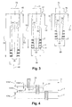
- the figure 3 shows schematically a sectional view of the sockets of a family of fasteners according to the invention.
- the family of devices for a given diameter, consists of N sub-families, each subfamily comprising several devices having different heights and an identical conicity rate.
- the family comprises, for a diameter 49, three sub-families 46, 47 and 48 whose conicity rates are respectively 1%, 2.5% and 4% and whose outer diameter 49 is identical .
- the minimum height of a bush is equal to the maximum height of a bush of the subfamily N-1 so as to have a continuity on the beach. thicknesses to be tightened.
- the minimum bushing height 50 of the subfamily 47 is equal to the maximum bushing height 51 of the subfamily 46 and the minimum bushing height 52 of the subfamily 48 is equal to the height maximum socket size of subfamily 47.
- the height of the bushings evolves in intervals of sixteenths of an inch, ie of 1.5875 millimeters.
- a plurality of horizontal parallel solid lines represent sleeve heights one-sixteenth of an inch apart in each of the sub-families 46, 47 and 48.
- the minimum outside diameter of a bushing is 15.04 mm, with a height between one this diameter, that is to say 15.04 mm and ten times this diameter, that is to say say 150.4 mm.
- the family according to the invention comprising the three sub-families 46, 47 and 48 makes it possible to tighten reamed elements with a diameter slightly greater than 35 mm and having a thickness of between 52 millimeters and 142 millimeters.
- the diameters 49 and 74 are identical for all the devices of the three sub-families 46, 47 and 48, regardless of their height.
- the smallest inner surface diameter 58 is the same for each device having the largest height of the three sub-families 46, 47 and 48.
- the diameter 58 is different for each larger device of a subfamily.
- the oblique solid lines 56 correspond to the frustoconical inner surface of the taller sleeve 51.
- the smaller inside diameter 58 of the larger sleeve is projected along this truncated cone 56 and thus varies in function of the height of the socket.
- all the sockets of the subfamily 46 have an identical conicity ratio.
- the taper ratio of the sockets of subfamily 46 is here equal, for example, to the ratio, in percentage, of the difference between the largest diameter 74 and the smallest diameter 58 of its frustoconical inner surface 56 by its height 51. .
- the oblique solid lines 60 correspond to the frustoconical inner surface of the taller bush 53.
- the smaller inner diameter 58 of the larger bushing is projected along this truncated cone 60 and therefore varies in size. function of the height of the socket.
- all the sockets of the subfamily 47 have an identical conicity rate.
- the degree of conicity of the sockets of subfamily 47 is here equal, for example, to the ratio, in percentage, of the difference between the largest diameter 74 and the smallest diameter 58 of its frustoconical inner surface. 60 by its height 53.
- the subfamily 47 comprises in particular three sockets X, Y and Z of different height. Each height being separated by one-sixteenth of an inch.
- the oblique solid lines 64 correspond to the frustoconical inner surface of the taller sleeve 55.
- the smaller inner diameter 58 of the larger sleeve is projected along this truncated cone 64 and therefore varies in size. function of the height of the socket.
- all the sockets of the subfamily 48 have an identical conicity rate.
- the taper ratio of the sockets of the subfamily 48 is here equal, for example, to the ratio, in percentage, of the difference between the largest diameter 74 and the smallest diameter 58 of its frustoconical inner surface 64 by its height 55. .
- the figure 4 represents schematically a close-up view of the acceptable clamping ranges by the X, Y and Z devices.
- the clamping range being the difference between the maximum and the minimum of the structural thicknesses that can be assembled with one another. device.
- An overlapping area 77 makes it possible to use either the X or Y socket interchangeably to tighten the same element thickness included in this range.
- the overlapping range 77 corresponds to a double margin 78 and 79 of a sixty-fourth inch each.
- This overlapping range 77 of one thirty-second of an inch makes it possible to assemble a thickness of structure included in this overlapping range whether with the sleeve X or Y, this is of interest when the thickness to be clamped is close the end of the clamping range of X or at the very beginning of the clamping range of Y and an uncertainty exists in the choice of X or Y.
- This cover range 77 can also compensate for a settlement of the structure during assembly.
Landscapes
- Engineering & Computer Science (AREA)
- General Engineering & Computer Science (AREA)
- Mechanical Engineering (AREA)
- Connection Of Plates (AREA)
- Drilling And Boring (AREA)
- Gripping On Spindles (AREA)
- Mutual Connection Of Rods And Tubes (AREA)
- Insertion Pins And Rivets (AREA)
- Moulding By Coating Moulds (AREA)
Applications Claiming Priority (2)
| Application Number | Priority Date | Filing Date | Title |
|---|---|---|---|
| FR0953959A FR2946707B1 (fr) | 2009-06-13 | 2009-06-13 | Famille de dispositifs de fixation a conicite variable. |
| PCT/FR2010/051126 WO2010142901A1 (fr) | 2009-06-13 | 2010-06-08 | Famille de dispositifs de fixation à conicité variable |
Publications (2)
| Publication Number | Publication Date |
|---|---|
| EP2440795A1 EP2440795A1 (fr) | 2012-04-18 |
| EP2440795B1 true EP2440795B1 (fr) | 2016-06-01 |
Family
ID=41478533
Family Applications (1)
| Application Number | Title | Priority Date | Filing Date |
|---|---|---|---|
| EP10737959.6A Active EP2440795B1 (fr) | 2009-06-13 | 2010-06-08 | Famille de dispositifs de fixation à conicité variable |
Country Status (17)
| Country | Link |
|---|---|
| US (1) | US9341205B2 (enExample) |
| EP (1) | EP2440795B1 (enExample) |
| JP (1) | JP5755643B2 (enExample) |
| KR (1) | KR101728182B1 (enExample) |
| CN (1) | CN102459926B (enExample) |
| AU (1) | AU2010258497A1 (enExample) |
| BR (1) | BRPI1013134B1 (enExample) |
| CA (1) | CA2761986C (enExample) |
| FR (1) | FR2946707B1 (enExample) |
| IL (1) | IL215984A0 (enExample) |
| MA (1) | MA33335B1 (enExample) |
| MX (1) | MX337500B (enExample) |
| RU (1) | RU2494290C1 (enExample) |
| TN (1) | TN2011000584A1 (enExample) |
| TW (1) | TW201115036A (enExample) |
| WO (1) | WO2010142901A1 (enExample) |
| ZA (1) | ZA201107926B (enExample) |
Families Citing this family (13)
| Publication number | Priority date | Publication date | Assignee | Title |
|---|---|---|---|---|
| US8631734B2 (en) * | 2005-11-22 | 2014-01-21 | Robert Bosch Gmbh | Glide movement controller and power miter saw including such controller |
| FR2971306B1 (fr) * | 2011-02-07 | 2013-02-15 | Lisi Aerospace | Famille d'elements de fixation, calibre de controle et procede de controle du choix de longueur d'un element de fixation |
| FR2995372A1 (fr) | 2012-09-13 | 2014-03-14 | Lisi Aerospace | Dispositif de fixation |
| FR2998015B1 (fr) | 2012-11-12 | 2015-05-29 | Lisi Aerospace | Dispositif pour fixation etanche |
| FR3026446B1 (fr) | 2014-09-30 | 2017-12-01 | Lisi Aerospace | Fixation en interference lubrifiee |
| US9493296B1 (en) | 2015-06-02 | 2016-11-15 | Grant A. Young | Shipping strap assembly for a vibratory screening machine |
| US10400808B2 (en) | 2016-03-10 | 2019-09-03 | The Boeing Company | One-sided fastener assembly and methods and systems for installing the same |
| DE102016112782B4 (de) * | 2016-07-12 | 2018-05-30 | Fairchild Fasteners Europe - Camloc Gmbh | Einsatz zur Verbindung eines elektrischen Anschlusses mit einer Wand |
| US11365757B2 (en) | 2016-08-12 | 2022-06-21 | Lisi Aerospace | Fastener with lubricating ring for interference fitting, and assembly method using such a fastener |
| FR3055034B1 (fr) | 2016-08-12 | 2019-05-17 | Lisi Aerospace | Fixation a anneau lubrifiant pour pose en interference et procede d'assemblage au moyen d'une telle fixation |
| FR3055040B1 (fr) | 2016-08-12 | 2019-05-17 | Lisi Aerospace | Capuchon lubrifiant, fixation comprenant un tel capuchon et procede d'assemblage en interference |
| WO2019155245A1 (en) | 2018-02-07 | 2019-08-15 | Lisi Aerospace | Fastener with lubricating ring for interference fitting, and assembly method using such a fastener |
| CN114378716B (zh) * | 2021-12-13 | 2023-04-11 | 西安赛尔电子材料科技有限公司 | 多直径及多高度的引线端面的打磨方法 |
Family Cites Families (27)
| Publication number | Priority date | Publication date | Assignee | Title |
|---|---|---|---|---|
| US1767019A (en) * | 1927-04-08 | 1930-06-24 | Sergeeff George | Dowel |
| US1823428A (en) * | 1930-02-14 | 1931-09-15 | Nat Supply Co | Anchorage device |
| US3034611A (en) * | 1958-05-07 | 1962-05-15 | Zenzic John | Tapered locking device |
| US3270410A (en) | 1963-05-20 | 1966-09-06 | Briles Mfg | Method of prestressed fastening of materials |
| US3271058A (en) * | 1963-05-22 | 1966-09-06 | Anderson Greenwood & Co | Tapered fastener |
| US3298725A (en) * | 1964-10-01 | 1967-01-17 | John C Boteler | High-strength fastener |
| US3603626A (en) * | 1969-01-27 | 1971-09-07 | Standard Pressed Steel Co | High-strength joint and fastener assembly therefor |
| US3641865A (en) * | 1970-04-20 | 1972-02-15 | Blake Rivet Co | Sealing shear fastener |
| US3821871A (en) * | 1970-08-05 | 1974-07-02 | Boeing Co | Fatigue resistant fasteners |
| US4048898A (en) * | 1974-10-17 | 1977-09-20 | Paul R. Briles | Fastener for multi metal stack-ups |
| US4087896A (en) * | 1976-09-17 | 1978-05-09 | Paul R. Briles | Sleeve bolt installation nut |
| SU1224475A1 (ru) * | 1983-01-10 | 1986-04-15 | Предприятие П/Я В-2190 | Разъемное соединение деталей |
| US4702658A (en) | 1983-08-22 | 1987-10-27 | Paul R. Briles | Apparatus for reducing installation forces and costs in a tapered bolt installation |
| US4974989A (en) * | 1983-08-22 | 1990-12-04 | Larry Salter | Method for reducing installation forces and costs in a tapered bolt installation |
| US5521951A (en) * | 1994-09-23 | 1996-05-28 | General Electric Company | Reactor core shroud repair with tapered pins |
| JPH11247873A (ja) * | 1998-02-26 | 1999-09-14 | Mitsubishi Heavy Ind Ltd | ボルト締結構造 |
| US6233802B1 (en) * | 1999-08-06 | 2001-05-22 | Huck International, Inc. | Low swage load fastener and fastening system |
| JP2002036286A (ja) * | 2000-07-26 | 2002-02-05 | Denso Corp | インサート金具および樹脂成形品の取付構造 |
| JP2002139015A (ja) * | 2000-11-02 | 2002-05-17 | Mitsubishi Heavy Ind Ltd | ボルトの締付け方法 |
| JP2002349529A (ja) * | 2001-05-31 | 2002-12-04 | Toshiba Corp | 締結装置 |
| GB2383105A (en) * | 2001-12-11 | 2003-06-18 | Rolls Royce Plc | Expansion bolt assembly |
| DE102005008497A1 (de) * | 2005-02-24 | 2006-08-31 | Siemens Ag | Verbindung von zwei Blechen durch Nieten oder Schrauben |
| DE102005022449A1 (de) * | 2005-05-14 | 2006-11-30 | Fischerwerke Artur Fischer Gmbh & Co. Kg | Abstandshalter für die Befestigung eines Gegenstandes an einem eine Dämmschicht aufweisenden Untergrund |
| DE102006058140B4 (de) * | 2006-03-22 | 2009-06-10 | Airbus Deutschland Gmbh | Bolzenverbindung |
| DE102007044404A1 (de) * | 2007-09-18 | 2009-03-19 | P&S Vorspannsysteme Ag | Verbindungsanordnung bzw. Verbindungsverfahren mit allseitigem Kraftschluss |
| JP4185161B1 (ja) * | 2008-03-31 | 2008-11-26 | 株式会社日立エンジニアリング・アンド・サービス | 伸縮ユニオン継手及び流体移送配管系 |
| US8057145B2 (en) * | 2008-06-26 | 2011-11-15 | Jetyd Corp. | Radially expanding bolt assembly |
-
2009
- 2009-06-13 FR FR0953959A patent/FR2946707B1/fr not_active Expired - Fee Related
-
2010
- 2010-06-08 MA MA34414A patent/MA33335B1/fr unknown
- 2010-06-08 US US13/377,822 patent/US9341205B2/en active Active
- 2010-06-08 KR KR1020117029739A patent/KR101728182B1/ko not_active Expired - Fee Related
- 2010-06-08 WO PCT/FR2010/051126 patent/WO2010142901A1/fr not_active Ceased
- 2010-06-08 JP JP2012514519A patent/JP5755643B2/ja active Active
- 2010-06-08 RU RU2012101099/12A patent/RU2494290C1/ru active
- 2010-06-08 CN CN201080025826.3A patent/CN102459926B/zh active Active
- 2010-06-08 AU AU2010258497A patent/AU2010258497A1/en not_active Abandoned
- 2010-06-08 MX MX2011012655A patent/MX337500B/es active IP Right Grant
- 2010-06-08 BR BRPI1013134A patent/BRPI1013134B1/pt active IP Right Grant
- 2010-06-08 EP EP10737959.6A patent/EP2440795B1/fr active Active
- 2010-06-08 CA CA2761986A patent/CA2761986C/fr active Active
- 2010-06-11 TW TW099119051A patent/TW201115036A/zh unknown
-
2011
- 2011-10-27 IL IL215984A patent/IL215984A0/en unknown
- 2011-10-28 ZA ZA2011/07926A patent/ZA201107926B/en unknown
- 2011-11-16 TN TNP2011000584A patent/TN2011000584A1/fr unknown
Also Published As
| Publication number | Publication date |
|---|---|
| KR20120094828A (ko) | 2012-08-27 |
| WO2010142901A1 (fr) | 2010-12-16 |
| RU2494290C1 (ru) | 2013-09-27 |
| MX337500B (es) | 2016-03-03 |
| FR2946707A1 (fr) | 2010-12-17 |
| CA2761986A1 (fr) | 2010-12-16 |
| EP2440795A1 (fr) | 2012-04-18 |
| ZA201107926B (en) | 2012-09-26 |
| AU2010258497A1 (en) | 2012-01-19 |
| IL215984A0 (en) | 2012-01-31 |
| RU2012101099A (ru) | 2013-07-20 |
| JP2012530219A (ja) | 2012-11-29 |
| MX2011012655A (es) | 2012-03-14 |
| TW201115036A (en) | 2011-05-01 |
| FR2946707B1 (fr) | 2011-05-20 |
| MA33335B1 (fr) | 2012-06-01 |
| JP5755643B2 (ja) | 2015-07-29 |
| TN2011000584A1 (fr) | 2013-05-24 |
| CA2761986C (fr) | 2017-02-28 |
| BRPI1013134B1 (pt) | 2019-08-13 |
| CN102459926A (zh) | 2012-05-16 |
| US20120237289A1 (en) | 2012-09-20 |
| US9341205B2 (en) | 2016-05-17 |
| KR101728182B1 (ko) | 2017-04-18 |
| BRPI1013134A2 (pt) | 2016-03-29 |
| CN102459926B (zh) | 2014-06-25 |
Similar Documents
| Publication | Publication Date | Title |
|---|---|---|
| EP2440795B1 (fr) | Famille de dispositifs de fixation à conicité variable | |
| EP3200957B1 (fr) | Systeme a extraction de demontage pour une turbomachine | |
| EP1121553B1 (fr) | Assemblage filete integral de deux tubes metalliques | |
| EP2702280B1 (fr) | Boulon a sertir en aveugle | |
| EP3482088B1 (fr) | Rivet de fixation aveugle avec fût épaulé et procédé d'installation associé | |
| EP3008351B1 (fr) | Dispositif de fixation de deux pieces entre elles | |
| FR3037369A1 (fr) | Fixation installee d'un seul cote a douille deformable | |
| FR2931911A1 (fr) | Systeme et procede d'assemblage par brides entre deux pieces tournantes | |
| FR2947596A1 (fr) | Insert taraude pour alesage cylindrique et equipement d'installation d'un tel insert | |
| EP3695129B1 (fr) | Ecrou rainuré pour fixation aveugle, rivet et assemblage comportant un tel écrou | |
| EP2344775B1 (fr) | Dispositif de fixation aveugle | |
| EP3688324B1 (fr) | Dispositif de blocage d'écrou et ensemble de montage associé | |
| CH695389A5 (fr) | Dispositif d'assemblage à vis d'au moins deux pièces, notamment de maillons de bracelet. | |
| EP2704867A1 (fr) | Outil de perçage polyvalent, et boîte associée | |
| EP3859170B1 (fr) | Boulon comprenant un écrou et au moins une rondelle obtenue par durcissement d'un matériau pâteux, procédé de montage dudit boulon et assemblage comportant au moins un tel boulon | |
| FR2983266A1 (fr) | Organe de fixation et son procede d'installation | |
| FR2826698A1 (fr) | Ensemble de fixation, module et fourreau de protection correspondants | |
| FR2537672A1 (fr) | Appareil de fixation aveugle et assemblage comportant un tel appareil | |
| FR2991023A1 (fr) | Dispositif de raccord, systeme de refroidissement comprenant un tel dispositif et procede de mise en oeuvre d'un tel dispositif | |
| WO1999037930A1 (fr) | Charniere pour application en micromecanique | |
| FR2735820A1 (fr) | Boulon a rondelle et son procede de fabrication | |
| FR3029580A1 (fr) | Vis pour moyen d'assemblage de deux pieces | |
| FR3032246A1 (fr) | Ecrou a sertir et ensemble de fixation comprenant un tel ecrou | |
| FR2727176A1 (fr) | Emmanchement conique |
Legal Events
| Date | Code | Title | Description |
|---|---|---|---|
| PUAI | Public reference made under article 153(3) epc to a published international application that has entered the european phase |
Free format text: ORIGINAL CODE: 0009012 |
|
| 17P | Request for examination filed |
Effective date: 20111103 |
|
| AK | Designated contracting states |
Kind code of ref document: A1 Designated state(s): AL AT BE BG CH CY CZ DE DK EE ES FI FR GB GR HR HU IE IS IT LI LT LU LV MC MK MT NL NO PL PT RO SE SI SK SM TR |
|
| DAX | Request for extension of the european patent (deleted) | ||
| RAP1 | Party data changed (applicant data changed or rights of an application transferred) |
Owner name: LISI AEROSPACE |
|
| GRAP | Despatch of communication of intention to grant a patent |
Free format text: ORIGINAL CODE: EPIDOSNIGR1 |
|
| INTG | Intention to grant announced |
Effective date: 20151223 |
|
| GRAS | Grant fee paid |
Free format text: ORIGINAL CODE: EPIDOSNIGR3 |
|
| GRAA | (expected) grant |
Free format text: ORIGINAL CODE: 0009210 |
|
| AK | Designated contracting states |
Kind code of ref document: B1 Designated state(s): AL AT BE BG CH CY CZ DE DK EE ES FI FR GB GR HR HU IE IS IT LI LT LU LV MC MK MT NL NO PL PT RO SE SI SK SM TR |
|
| REG | Reference to a national code |
Ref country code: GB Ref legal event code: FG4D Free format text: NOT ENGLISH |
|
| REG | Reference to a national code |
Ref country code: CH Ref legal event code: EP Ref country code: AT Ref legal event code: REF Ref document number: 804059 Country of ref document: AT Kind code of ref document: T Effective date: 20160615 |
|
| REG | Reference to a national code |
Ref country code: IE Ref legal event code: FG4D Free format text: LANGUAGE OF EP DOCUMENT: FRENCH |
|
| REG | Reference to a national code |
Ref country code: DE Ref legal event code: R096 Ref document number: 602010033779 Country of ref document: DE |
|
| REG | Reference to a national code |
Ref country code: LT Ref legal event code: MG4D |
|
| REG | Reference to a national code |
Ref country code: NL Ref legal event code: MP Effective date: 20160601 |
|
| REG | Reference to a national code |
Ref country code: FR Ref legal event code: PLFP Year of fee payment: 7 |
|
| PG25 | Lapsed in a contracting state [announced via postgrant information from national office to epo] |
Ref country code: NO Free format text: LAPSE BECAUSE OF FAILURE TO SUBMIT A TRANSLATION OF THE DESCRIPTION OR TO PAY THE FEE WITHIN THE PRESCRIBED TIME-LIMIT Effective date: 20160901 Ref country code: FI Free format text: LAPSE BECAUSE OF FAILURE TO SUBMIT A TRANSLATION OF THE DESCRIPTION OR TO PAY THE FEE WITHIN THE PRESCRIBED TIME-LIMIT Effective date: 20160601 Ref country code: LT Free format text: LAPSE BECAUSE OF FAILURE TO SUBMIT A TRANSLATION OF THE DESCRIPTION OR TO PAY THE FEE WITHIN THE PRESCRIBED TIME-LIMIT Effective date: 20160601 |
|
| REG | Reference to a national code |
Ref country code: AT Ref legal event code: MK05 Ref document number: 804059 Country of ref document: AT Kind code of ref document: T Effective date: 20160601 |
|
| PG25 | Lapsed in a contracting state [announced via postgrant information from national office to epo] |
Ref country code: HR Free format text: LAPSE BECAUSE OF FAILURE TO SUBMIT A TRANSLATION OF THE DESCRIPTION OR TO PAY THE FEE WITHIN THE PRESCRIBED TIME-LIMIT Effective date: 20160601 Ref country code: GR Free format text: LAPSE BECAUSE OF FAILURE TO SUBMIT A TRANSLATION OF THE DESCRIPTION OR TO PAY THE FEE WITHIN THE PRESCRIBED TIME-LIMIT Effective date: 20160902 Ref country code: NL Free format text: LAPSE BECAUSE OF FAILURE TO SUBMIT A TRANSLATION OF THE DESCRIPTION OR TO PAY THE FEE WITHIN THE PRESCRIBED TIME-LIMIT Effective date: 20160601 Ref country code: SE Free format text: LAPSE BECAUSE OF FAILURE TO SUBMIT A TRANSLATION OF THE DESCRIPTION OR TO PAY THE FEE WITHIN THE PRESCRIBED TIME-LIMIT Effective date: 20160601 Ref country code: ES Free format text: LAPSE BECAUSE OF FAILURE TO SUBMIT A TRANSLATION OF THE DESCRIPTION OR TO PAY THE FEE WITHIN THE PRESCRIBED TIME-LIMIT Effective date: 20160601 Ref country code: LV Free format text: LAPSE BECAUSE OF FAILURE TO SUBMIT A TRANSLATION OF THE DESCRIPTION OR TO PAY THE FEE WITHIN THE PRESCRIBED TIME-LIMIT Effective date: 20160601 |
|
| PG25 | Lapsed in a contracting state [announced via postgrant information from national office to epo] |
Ref country code: BE Free format text: LAPSE BECAUSE OF NON-PAYMENT OF DUE FEES Effective date: 20160630 |
|
| PG25 | Lapsed in a contracting state [announced via postgrant information from national office to epo] |
Ref country code: RO Free format text: LAPSE BECAUSE OF FAILURE TO SUBMIT A TRANSLATION OF THE DESCRIPTION OR TO PAY THE FEE WITHIN THE PRESCRIBED TIME-LIMIT Effective date: 20160601 Ref country code: EE Free format text: LAPSE BECAUSE OF FAILURE TO SUBMIT A TRANSLATION OF THE DESCRIPTION OR TO PAY THE FEE WITHIN THE PRESCRIBED TIME-LIMIT Effective date: 20160601 Ref country code: IT Free format text: LAPSE BECAUSE OF FAILURE TO SUBMIT A TRANSLATION OF THE DESCRIPTION OR TO PAY THE FEE WITHIN THE PRESCRIBED TIME-LIMIT Effective date: 20160601 Ref country code: CZ Free format text: LAPSE BECAUSE OF FAILURE TO SUBMIT A TRANSLATION OF THE DESCRIPTION OR TO PAY THE FEE WITHIN THE PRESCRIBED TIME-LIMIT Effective date: 20160601 Ref country code: SK Free format text: LAPSE BECAUSE OF FAILURE TO SUBMIT A TRANSLATION OF THE DESCRIPTION OR TO PAY THE FEE WITHIN THE PRESCRIBED TIME-LIMIT Effective date: 20160601 Ref country code: IS Free format text: LAPSE BECAUSE OF FAILURE TO SUBMIT A TRANSLATION OF THE DESCRIPTION OR TO PAY THE FEE WITHIN THE PRESCRIBED TIME-LIMIT Effective date: 20161001 |
|
| REG | Reference to a national code |
Ref country code: CH Ref legal event code: PL |
|
| PG25 | Lapsed in a contracting state [announced via postgrant information from national office to epo] |
Ref country code: PT Free format text: LAPSE BECAUSE OF FAILURE TO SUBMIT A TRANSLATION OF THE DESCRIPTION OR TO PAY THE FEE WITHIN THE PRESCRIBED TIME-LIMIT Effective date: 20161003 Ref country code: PL Free format text: LAPSE BECAUSE OF FAILURE TO SUBMIT A TRANSLATION OF THE DESCRIPTION OR TO PAY THE FEE WITHIN THE PRESCRIBED TIME-LIMIT Effective date: 20160601 Ref country code: SM Free format text: LAPSE BECAUSE OF FAILURE TO SUBMIT A TRANSLATION OF THE DESCRIPTION OR TO PAY THE FEE WITHIN THE PRESCRIBED TIME-LIMIT Effective date: 20160601 Ref country code: AT Free format text: LAPSE BECAUSE OF FAILURE TO SUBMIT A TRANSLATION OF THE DESCRIPTION OR TO PAY THE FEE WITHIN THE PRESCRIBED TIME-LIMIT Effective date: 20160601 |
|
| REG | Reference to a national code |
Ref country code: DE Ref legal event code: R097 Ref document number: 602010033779 Country of ref document: DE |
|
| REG | Reference to a national code |
Ref country code: IE Ref legal event code: MM4A |
|
| PG25 | Lapsed in a contracting state [announced via postgrant information from national office to epo] |
Ref country code: MC Free format text: LAPSE BECAUSE OF FAILURE TO SUBMIT A TRANSLATION OF THE DESCRIPTION OR TO PAY THE FEE WITHIN THE PRESCRIBED TIME-LIMIT Effective date: 20160601 |
|
| PLBE | No opposition filed within time limit |
Free format text: ORIGINAL CODE: 0009261 |
|
| STAA | Information on the status of an ep patent application or granted ep patent |
Free format text: STATUS: NO OPPOSITION FILED WITHIN TIME LIMIT |
|
| PG25 | Lapsed in a contracting state [announced via postgrant information from national office to epo] |
Ref country code: LI Free format text: LAPSE BECAUSE OF NON-PAYMENT OF DUE FEES Effective date: 20160630 Ref country code: CH Free format text: LAPSE BECAUSE OF NON-PAYMENT OF DUE FEES Effective date: 20160630 |
|
| 26N | No opposition filed |
Effective date: 20170302 |
|
| PG25 | Lapsed in a contracting state [announced via postgrant information from national office to epo] |
Ref country code: DK Free format text: LAPSE BECAUSE OF FAILURE TO SUBMIT A TRANSLATION OF THE DESCRIPTION OR TO PAY THE FEE WITHIN THE PRESCRIBED TIME-LIMIT Effective date: 20160601 Ref country code: IE Free format text: LAPSE BECAUSE OF NON-PAYMENT OF DUE FEES Effective date: 20160608 Ref country code: SI Free format text: LAPSE BECAUSE OF FAILURE TO SUBMIT A TRANSLATION OF THE DESCRIPTION OR TO PAY THE FEE WITHIN THE PRESCRIBED TIME-LIMIT Effective date: 20160601 |
|
| REG | Reference to a national code |
Ref country code: FR Ref legal event code: PLFP Year of fee payment: 8 |
|
| PG25 | Lapsed in a contracting state [announced via postgrant information from national office to epo] |
Ref country code: CY Free format text: LAPSE BECAUSE OF FAILURE TO SUBMIT A TRANSLATION OF THE DESCRIPTION OR TO PAY THE FEE WITHIN THE PRESCRIBED TIME-LIMIT Effective date: 20160601 Ref country code: HU Free format text: LAPSE BECAUSE OF FAILURE TO SUBMIT A TRANSLATION OF THE DESCRIPTION OR TO PAY THE FEE WITHIN THE PRESCRIBED TIME-LIMIT; INVALID AB INITIO Effective date: 20100608 |
|
| PG25 | Lapsed in a contracting state [announced via postgrant information from national office to epo] |
Ref country code: TR Free format text: LAPSE BECAUSE OF FAILURE TO SUBMIT A TRANSLATION OF THE DESCRIPTION OR TO PAY THE FEE WITHIN THE PRESCRIBED TIME-LIMIT Effective date: 20160601 Ref country code: MT Free format text: LAPSE BECAUSE OF FAILURE TO SUBMIT A TRANSLATION OF THE DESCRIPTION OR TO PAY THE FEE WITHIN THE PRESCRIBED TIME-LIMIT Effective date: 20160601 Ref country code: MK Free format text: LAPSE BECAUSE OF FAILURE TO SUBMIT A TRANSLATION OF THE DESCRIPTION OR TO PAY THE FEE WITHIN THE PRESCRIBED TIME-LIMIT Effective date: 20160601 Ref country code: LU Free format text: LAPSE BECAUSE OF NON-PAYMENT OF DUE FEES Effective date: 20160608 |
|
| REG | Reference to a national code |
Ref country code: FR Ref legal event code: PLFP Year of fee payment: 9 |
|
| PG25 | Lapsed in a contracting state [announced via postgrant information from national office to epo] |
Ref country code: BG Free format text: LAPSE BECAUSE OF FAILURE TO SUBMIT A TRANSLATION OF THE DESCRIPTION OR TO PAY THE FEE WITHIN THE PRESCRIBED TIME-LIMIT Effective date: 20160601 |
|
| PG25 | Lapsed in a contracting state [announced via postgrant information from national office to epo] |
Ref country code: AL Free format text: LAPSE BECAUSE OF FAILURE TO SUBMIT A TRANSLATION OF THE DESCRIPTION OR TO PAY THE FEE WITHIN THE PRESCRIBED TIME-LIMIT Effective date: 20160601 |
|
| REG | Reference to a national code |
Ref country code: DE Ref legal event code: R082 Ref document number: 602010033779 Country of ref document: DE Representative=s name: LAVOIX MUNICH, DE |
|
| PGFP | Annual fee paid to national office [announced via postgrant information from national office to epo] |
Ref country code: DE Payment date: 20250617 Year of fee payment: 16 |
|
| PGFP | Annual fee paid to national office [announced via postgrant information from national office to epo] |
Ref country code: GB Payment date: 20250625 Year of fee payment: 16 |
|
| PGFP | Annual fee paid to national office [announced via postgrant information from national office to epo] |
Ref country code: FR Payment date: 20250630 Year of fee payment: 16 |