EP2440795B1 - Family of fixation devices with variable taper - Google Patents
Family of fixation devices with variable taper Download PDFInfo
- Publication number
- EP2440795B1 EP2440795B1 EP10737959.6A EP10737959A EP2440795B1 EP 2440795 B1 EP2440795 B1 EP 2440795B1 EP 10737959 A EP10737959 A EP 10737959A EP 2440795 B1 EP2440795 B1 EP 2440795B1
- Authority
- EP
- European Patent Office
- Prior art keywords
- interference
- bushing
- taper
- family according
- screw
- Prior art date
- Legal status (The legal status is an assumption and is not a legal conclusion. Google has not performed a legal analysis and makes no representation as to the accuracy of the status listed.)
- Active
Links
- 238000009434 installation Methods 0.000 claims description 15
- 239000002131 composite material Substances 0.000 description 7
- 229910052751 metal Inorganic materials 0.000 description 5
- 230000032798 delamination Effects 0.000 description 4
- 239000002184 metal Substances 0.000 description 4
- 239000007769 metal material Substances 0.000 description 4
- RTAQQCXQSZGOHL-UHFFFAOYSA-N Titanium Chemical compound [Ti] RTAQQCXQSZGOHL-UHFFFAOYSA-N 0.000 description 2
- 239000011248 coating agent Substances 0.000 description 2
- 238000000576 coating method Methods 0.000 description 2
- 238000003754 machining Methods 0.000 description 2
- 239000010936 titanium Substances 0.000 description 2
- 229910052719 titanium Inorganic materials 0.000 description 2
- 229910000838 Al alloy Inorganic materials 0.000 description 1
- 229910052782 aluminium Inorganic materials 0.000 description 1
- XAGFODPZIPBFFR-UHFFFAOYSA-N aluminium Chemical compound [Al] XAGFODPZIPBFFR-UHFFFAOYSA-N 0.000 description 1
- 230000000712 assembly Effects 0.000 description 1
- 238000000429 assembly Methods 0.000 description 1
- 238000005520 cutting process Methods 0.000 description 1
- 238000005553 drilling Methods 0.000 description 1
- 230000008030 elimination Effects 0.000 description 1
- 238000003379 elimination reaction Methods 0.000 description 1
- 238000004519 manufacturing process Methods 0.000 description 1
- 239000000463 material Substances 0.000 description 1
- 238000000034 method Methods 0.000 description 1
- 230000001737 promoting effect Effects 0.000 description 1
- 239000010935 stainless steel Substances 0.000 description 1
- 229910001220 stainless steel Inorganic materials 0.000 description 1
- 239000002699 waste material Substances 0.000 description 1
Images
Classifications
-
- F—MECHANICAL ENGINEERING; LIGHTING; HEATING; WEAPONS; BLASTING
- F16—ENGINEERING ELEMENTS AND UNITS; GENERAL MEASURES FOR PRODUCING AND MAINTAINING EFFECTIVE FUNCTIONING OF MACHINES OR INSTALLATIONS; THERMAL INSULATION IN GENERAL
- F16B—DEVICES FOR FASTENING OR SECURING CONSTRUCTIONAL ELEMENTS OR MACHINE PARTS TOGETHER, e.g. NAILS, BOLTS, CIRCLIPS, CLAMPS, CLIPS OR WEDGES; JOINTS OR JOINTING
- F16B5/00—Joining sheets or plates, e.g. panels, to one another or to strips or bars parallel to them
- F16B5/02—Joining sheets or plates, e.g. panels, to one another or to strips or bars parallel to them by means of fastening members using screw-thread
-
- F—MECHANICAL ENGINEERING; LIGHTING; HEATING; WEAPONS; BLASTING
- F16—ENGINEERING ELEMENTS AND UNITS; GENERAL MEASURES FOR PRODUCING AND MAINTAINING EFFECTIVE FUNCTIONING OF MACHINES OR INSTALLATIONS; THERMAL INSULATION IN GENERAL
- F16B—DEVICES FOR FASTENING OR SECURING CONSTRUCTIONAL ELEMENTS OR MACHINE PARTS TOGETHER, e.g. NAILS, BOLTS, CIRCLIPS, CLAMPS, CLIPS OR WEDGES; JOINTS OR JOINTING
- F16B3/00—Key-type connections; Keys
- F16B3/06—Key-type connections; Keys using taper sleeves
Definitions
- the present invention relates to a family of variable taper fasteners.
- the technical field of the invention is, in general, that of screws and sockets. More particularly, the invention relates to screws and bushings for assembling aircraft structural elements pre-bored in a cylindrical manner.
- cylindrical and / or frustoconical screws made of metallic material and coated with a coating promoting their sliding within a metal are known. bore of elements to be assembled.
- US4048898 , US4702658 , and US3270410 discloses, respectively, a frustoconical device for fixing multilayer metal elements, a device for reducing forces and installation costs of a frustoconical fixing device and a fastening method for installing prestressing in a material.
- the conical barrel fasteners are usually used by aircraft manufacturers in the areas to be assembled which have accessibility difficulties and require interference.
- the interference is defined by the installation of a screw having a smooth portion which has an outside diameter greater than the bore diameter which will receive it, which causes an expansion of the bore during the installation of the screw.
- the installation of the interference screws is done simply by pulling them or by pushing them into the bore which by means of an optimized design of the input radius of the barrel of the screw and a coating to low coefficient of friction does not cause damage to the structure.
- the interference installation increases the fatigue life of the structure.
- the new generation of aircraft uses a composite material structure that has the advantage of significantly lightening the aircraft and is not sensitive to the phenomenon of fatigue but, unlike a metal structure, has the disadvantage of a poor conductivity and poses problems of resistance to the impacts of lightning. In order to resist the lightning, it is also necessary to fill any gap that exists between the fixing and the bore thus imposing an interference installation in the composites.
- the invention can also have applications in mixed structures that is to say using composite and metal materials such as aluminum alloy or titanium for example, the device will be installed in a series of metal / composite layers that form the aircraft structure; or also in only metal structures of the aluminum or titanium type for example, in this case there will be no risk of delamination but the advantage of the use of the invention lies in the fact of the elimination of holes conical.
- the taper ratio of the sleeves according to the invention is between a few tenths of a percent and 10%.
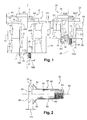
- the figure 1 schematically represents a sectional view of a first example of a family of element fixing devices, according to the invention.
- the elements to be assembled constitute an aircraft structure and the family comprises two fastening devices 1 and 20.
- the device 1 is shown on the left side A1 of its axis of symmetry 5 passing through it in the middle, before interference, that is to say at the very beginning of the installation, when it has been inserted without effort, with play. and without radial expansion, in the structure of the aircraft.
- the device is shown after interference by radial expansion in the structure, the right side B1 of the axis 5, the cutting plane being defined by this axis 5.
- the device 20 is shown before interference, the left side A20 of its axis of symmetry 24 passing through it in the middle.
- the device is shown, after interference, on the right side B20 of the axis 24, the section plane being defined by this axis 24.
- the fixing device 1 is intended to assemble four previously bored cylindrical structural elements 40, 41, 42 and 43, with a diameter 18.
- the elements 40, 41, 42 and 43 to assemble have an overall thickness referenced 12.
- the device 1 comprises a screw 4 extending along the axis 5.
- the screw 4 comprises a frustoconical barrel 6 extending on one side in a flat cylindrical head 7 and, on the other hand, in a thread 17.
- the head 7 forms a disk whose plane is perpendicular to the axis 5, the disk being intended to be disposed substantially parallel to an upper surface 13 of the element.
- the device 1 also comprises a bushing 8 intended to receive the frustoconical drum 6 of the screw 4 therein.
- the bushing 8 extends along the same axis 5 and has a cylindrical outer surface 9 and a frustoconical inner surface 10.
- a distance, called protrusion P1 separates, before interference, a lower surface 14 of the screw head 7 and an upper surface 15 of the bushing 8.
- an initial clearance J1 mounting between an outer diameter 16A of the sleeve 8 before interference and the bore diameter 18 of the elements 40, 41 , 42 and 43 is provided.
- the initial clearance and the expansion are controlled by pre-machining in the factory, the external diameter with a precision of the order of a few tens of microns, the bushing with its pre-screw -managed to protrusion P1, itself also controlled in the factory.
- the fixing device 20 is intended to assemble two previously bored cylindrical structural elements 44 and 45 with the same diameter 18.
- the elements to be assembled comprise two layers 44 and 45 whose overall thickness is referenced 31.
- the device 20 comprises a screw 23 extending along the axis 24.
- the screw 23 comprises a frustoconical barrel 25 extending on one side into a flat cylindrical head 26 and, on the other side, into a thread 39
- the head 26 forms a disk whose plane is perpendicular to the axis 24, the disk being intended to be disposed substantially parallel to an upper surface 32 of the element 44.
- the device 20 also comprises a sleeve 27 intended to receive the frustoconical barrel 25 of the screw 23 therein.
- the sleeve 27 extends along the same axis 24 and has a cylindrical outer surface 28 and a frustoconical inner surface 29.
- a protrusion P2 separates, before interference, a lower surface 33 of the screw head 23 and an upper surface 34 of the sleeve 27.
- the screws 4 and 23 are driven by pulling via a nut screwed around the thread 17 or with the aid of a pulling chuck or pushing on the head.
- an interference is made between the screw, the socket and the element to be assembled, over the entire thickness.
- This interference corresponds to a difference IF1 and IF2 between a diameter 18 of the bore and an outside diameter 16B and 16D of the sleeve after interference.
- the interference is chosen and predetermined to at least offset the initial clearance, i.e fill the empty space, exerting a radial pressure on the element to be assembled, and thus pre-constrain the assembly radially.
- the two devices 1 and 20 thus comprise sockets 8 and 27 having, before interference, an outer diameter 16A and 16C identical and a C1 and C2 rate of conicity of different inner surface. More precisely, the taper ratio formed by the axis 5 and 24 and the frustoconical surface 10 and 29 of the sockets 8 and 27, respectively, varies inversely with the height 19 and 30 of the sockets 8 and 27 respectively.
- the conicity rate is between a few tenths of a percent and 10%, preferably between 1% and 4%.
- the taper ratio of the barrel 6 and 25 of the screw 4 and 23 is the same as that of the inner surface 10 and 29 of the bushing 8 and 27, respectively.
- the taper ratio of the barrel 6 and 25 of the screw 4 and 23 may be substantially different from the inner surface 10 and 29. the bushing 8 and 27 to generate variable interference, controlled, along the thickness.
- the conicity rate may vary locally within the same subfamily so as to adjust the interference in a defined area.
- the height 19 and 30 of the sleeves 8 and 27 corresponds, at least, to their outer diameter after interference 16B and 16D and, at most, to ten times this diameter.
- the degree of conicity of the bushing 8 is here equal to the ratio, in percentage, of the difference between its largest diameter D8 and its smaller diameter d8 of its frustoconical inner surface 10 by its height 19.
- C8 (D8 - d8) / 19.
- the taper ratio of the sleeve 27 is here equal to the ratio, in percentage, of the difference between its largest diameter D27 and its smaller diameter d27 of its frustoconical inner surface 29 by its height 30.
- C27 (D27 - d27) / 30.
- the figure 2 schematically represents a sectional view of another example of a fixing device 80 according to the invention.
- This is a countersunk device.
- the device 80 comprises a screw 81 extending along an axis 82.
- the screw 81 comprises a frustoconical drum 83 extending on one side in a countersunk head 84 and, on the other side, in a thread 85.
- the end upper 86 of the countersunk head 84 forms a disk whose plane is perpendicular to the axis 82, the disk being intended to be disposed of substantially parallel to an upper surface of the elements to be assembled.
- the device 80 also comprises a bushing 87 adapted for and intended for the screw 81.
- the bushing 87 comprises a cylindro-conical drum 88 adapted to receive the frustoconical drum 83 of the screw 81 therein and a frustoconical portion 93 adapted to receive the head
- the bushing 87 extends along the same axis 82 and has a cylindrical outer surface 89 and a frustoconical inner surface 90.
- a distance, called protrusion P3 separates, before interference, a lower surface 91 of the screw head 84 and an upper surface 92 of the sleeve 87.
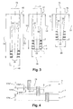
- the figure 3 shows schematically a sectional view of the sockets of a family of fasteners according to the invention.
- the family of devices for a given diameter, consists of N sub-families, each subfamily comprising several devices having different heights and an identical conicity rate.
- the family comprises, for a diameter 49, three sub-families 46, 47 and 48 whose conicity rates are respectively 1%, 2.5% and 4% and whose outer diameter 49 is identical .
- the minimum height of a bush is equal to the maximum height of a bush of the subfamily N-1 so as to have a continuity on the beach. thicknesses to be tightened.
- the minimum bushing height 50 of the subfamily 47 is equal to the maximum bushing height 51 of the subfamily 46 and the minimum bushing height 52 of the subfamily 48 is equal to the height maximum socket size of subfamily 47.
- the height of the bushings evolves in intervals of sixteenths of an inch, ie of 1.5875 millimeters.
- a plurality of horizontal parallel solid lines represent sleeve heights one-sixteenth of an inch apart in each of the sub-families 46, 47 and 48.
- the minimum outside diameter of a bushing is 15.04 mm, with a height between one this diameter, that is to say 15.04 mm and ten times this diameter, that is to say say 150.4 mm.
- the family according to the invention comprising the three sub-families 46, 47 and 48 makes it possible to tighten reamed elements with a diameter slightly greater than 35 mm and having a thickness of between 52 millimeters and 142 millimeters.
- the diameters 49 and 74 are identical for all the devices of the three sub-families 46, 47 and 48, regardless of their height.
- the smallest inner surface diameter 58 is the same for each device having the largest height of the three sub-families 46, 47 and 48.
- the diameter 58 is different for each larger device of a subfamily.
- the oblique solid lines 56 correspond to the frustoconical inner surface of the taller sleeve 51.
- the smaller inside diameter 58 of the larger sleeve is projected along this truncated cone 56 and thus varies in function of the height of the socket.
- all the sockets of the subfamily 46 have an identical conicity ratio.
- the taper ratio of the sockets of subfamily 46 is here equal, for example, to the ratio, in percentage, of the difference between the largest diameter 74 and the smallest diameter 58 of its frustoconical inner surface 56 by its height 51. .
- the oblique solid lines 60 correspond to the frustoconical inner surface of the taller bush 53.
- the smaller inner diameter 58 of the larger bushing is projected along this truncated cone 60 and therefore varies in size. function of the height of the socket.
- all the sockets of the subfamily 47 have an identical conicity rate.
- the degree of conicity of the sockets of subfamily 47 is here equal, for example, to the ratio, in percentage, of the difference between the largest diameter 74 and the smallest diameter 58 of its frustoconical inner surface. 60 by its height 53.
- the subfamily 47 comprises in particular three sockets X, Y and Z of different height. Each height being separated by one-sixteenth of an inch.
- the oblique solid lines 64 correspond to the frustoconical inner surface of the taller sleeve 55.
- the smaller inner diameter 58 of the larger sleeve is projected along this truncated cone 64 and therefore varies in size. function of the height of the socket.
- all the sockets of the subfamily 48 have an identical conicity rate.
- the taper ratio of the sockets of the subfamily 48 is here equal, for example, to the ratio, in percentage, of the difference between the largest diameter 74 and the smallest diameter 58 of its frustoconical inner surface 64 by its height 55. .
- the figure 4 represents schematically a close-up view of the acceptable clamping ranges by the X, Y and Z devices.
- the clamping range being the difference between the maximum and the minimum of the structural thicknesses that can be assembled with one another. device.
- An overlapping area 77 makes it possible to use either the X or Y socket interchangeably to tighten the same element thickness included in this range.
- the overlapping range 77 corresponds to a double margin 78 and 79 of a sixty-fourth inch each.
- This overlapping range 77 of one thirty-second of an inch makes it possible to assemble a thickness of structure included in this overlapping range whether with the sleeve X or Y, this is of interest when the thickness to be clamped is close the end of the clamping range of X or at the very beginning of the clamping range of Y and an uncertainty exists in the choice of X or Y.
- This cover range 77 can also compensate for a settlement of the structure during assembly.
Landscapes
- Engineering & Computer Science (AREA)
- General Engineering & Computer Science (AREA)
- Mechanical Engineering (AREA)
- Connection Of Plates (AREA)
- Gripping On Spindles (AREA)
- Drilling And Boring (AREA)
- Insertion Pins And Rivets (AREA)
- Mutual Connection Of Rods And Tubes (AREA)
- Moulding By Coating Moulds (AREA)
Description
La présente invention se rapporte à une famille de dispositifs de fixation à conicité variable. Le domaine technique de l'invention est, d'une façon générale, celui des vis et des douilles. Plus particulièrement, l'invention concerne des vis et des douilles destinées à assembler des éléments de structure d'avion préalablement alésés de manière cylindrique.The present invention relates to a family of variable taper fasteners. The technical field of the invention is, in general, that of screws and sockets. More particularly, the invention relates to screws and bushings for assembling aircraft structural elements pre-bored in a cylindrical manner.
Dans l'état de la technique, pour mettre en place des dispositifs de fixation au sein de tels éléments structurels, on connaît des vis cylindriques et/ou tronconiques réalisées en matériau métallique et recouvertes d'un revêtement favorisant leur glissement au sein d'un alésage d'éléments à assembler.In the state of the art, to set up fastening devices within such structural elements, cylindrical and / or frustoconical screws made of metallic material and coated with a coating promoting their sliding within a metal are known. bore of elements to be assembled.
Dans l'art antérieur, on connaît également l'enseignement des documents
La nouvelle génération d'avions utilise une structure en matériau composite qui a l'avantage d'alléger de manière significative l'avion et qui n'est pas sensible au phénomène de fatigue mais, contrairement à une structure métallique, a l'inconvénient d'une mauvaise conductivité et pose des problèmes de résistance aux impacts de foudre. Afin de résister à la foudre, il est là aussi nécessaire de combler tout jeu qui existerait entre la fixation et l'alésage imposant ainsi une installation en interférence dans les composites.The new generation of aircraft uses a composite material structure that has the advantage of significantly lightening the aircraft and is not sensitive to the phenomenon of fatigue but, unlike a metal structure, has the disadvantage of a poor conductivity and poses problems of resistance to the impacts of lightning. In order to resist the lightning, it is also necessary to fill any gap that exists between the fixing and the bore thus imposing an interference installation in the composites.
L'installation en interférence d'une fixation dans une structure composite présente des risques importants de délamination de ce dernier due au frottement de la partie lisse de la fixation sur l'alésage dans la structure composite, ce qui peut conduire à un endommagement par délaminage et donc une moindre résistance.The interference installation of a fastener in a composite structure presents significant risks of delamination of the latter due to the friction of the smooth part of the fastener on the bore in the composite structure, which can lead to damage by delamination. and therefore less resistance.
Ainsi l'utilisation d'une douille recouvrant la partie lisse de la fixation et installée, dans un premier temps, avec jeu dans la structure, s'avère nécessaire afin de protéger le matériau composite de toute délamination. Dans un deuxième temps, une expansion radiale de cette douille est requise de sorte que le jeu n'existe plus pour les raisons qui ont été vues précédemment.Thus the use of a sleeve covering the smooth part of the fastener and installed, initially, with play in the structure, is necessary to protect the composite material from any delamination. In a second step, a radial expansion of this sleeve is required so that the game no longer exists for the reasons that have been seen previously.
Pour le cas des fixations à fût conique, la réalisation d'alésages coniques dans les structures d'avion présente une certaine difficulté et incite l'homme du métier à utiliser une vis à fût conique chemisée d'une douille cylindro-conique, par exemple en acier inoxydable. Ce dispositif est ensuite installé dans l'alésage cylindrique de la structure afin de s'affranchir de l'usinage d'alésage conique.In the case of conical barrel fasteners, the production of conical bores in aircraft structures presents a certain difficulty and encourages the skilled person to use a screw with a conical barrel lined with a cylindro-conical bush, for example Stainless steel. This device is then installed in the cylindrical bore of the structure to overcome the tapered bore machining.
L'état de la technique actuel, basé sur le brevet
On a donc, dans l'état de la technique, autant de références de dispositifs de fixation que d'épaisseurs différentes d'éléments à assembler. Autrement dit, plus les éléments à assembler sont épais, plus le diamètre d'alésage desdits éléments et le diamètre de la douille sont grands. Cette grande diversité constitue un problème technique majeur pour l'homme du métier. En effet, il doit prévoir l'outil et le dispositif adéquates pour chaque épaisseur d'élément à serrer, ce qui représente un coût en outillage important et également une perte de temps due au changement d'outillage. De plus le fait d'avoir une diversité de taille d'alésage ne permet pas de prédire de façon simple et robuste la tenue structurale des éléments assemblés.In the state of the art, therefore, there are as many references for fastening devices as for different thicknesses of elements to be assembled. In other words, the thicker the elements to be assembled, the greater the bore diameter of said elements and the diameter of the sleeve. This great diversity is a major technical problem for the skilled person. Indeed, it must provide the tool and the appropriate device for each thickness of the element to be clamped, which represents a significant tooling cost and also a waste of time due to the change of tools. Moreover having a diversity of bore size does not predict in a simple and robust way the structural strength of the assembled elements.
L'homme du métier a résolu une partie du problème en créant des familles de perçage et de longueur, par repère de diamètre de fixation, et ainsi a réduit le nombre d'outillages mais sans aboutir à un outillage unique quelque soit la longueur à serrer comme il existe pour les fixations à partie lisse cylindrique.Those skilled in the art have solved part of the problem by creating families of drilling and length, by reference of fixing diameter, and thus reduced the number of tools but without resulting in a single tool whatever the length to be tightened as it exists for the fixings with cylindrical smooth part.
Dans l'invention, pour résoudre ce problème, on a eu l'idée d'adapter un taux de conicité du dispositif en fonction de sa hauteur. On entend par taux de conicité, un rapport, en pourcentage, de la différence entre le plus grand diamètre et le plus petit diamètre du tronc de cône par sa hauteur. Le taux de conicité est donc défini par la formule suivante : C = (D - d)/HIn the invention, to solve this problem, we had the idea to adapt a taper rate of the device according to its height. The term conicity is defined as a percentage ratio of the difference between the largest diameter and the smallest diameter of the truncated cone by its height. The taper ratio is therefore defined by the following formula: C = (D - d) / H
L'invention peut également avoir des applications dans des structures mixtes c'est à dire utilisant des matériaux composites et métalliques du type alliage d'aluminium ou de titane par exemple, le dispositif sera installé dans une succession de couches métallique/composite qui forme la structure de l'avion; ou également dans des structures uniquement métalliques du type aluminium ou titane par exemple, dans ce cas il n'y aura pas de risques de délamination mais l'intérêt de l'utilisation de l'invention résidera dans le fait de l'élimination de perçages coniques.The invention can also have applications in mixed structures that is to say using composite and metal materials such as aluminum alloy or titanium for example, the device will be installed in a series of metal / composite layers that form the aircraft structure; or also in only metal structures of the aluminum or titanium type for example, in this case there will be no risk of delamination but the advantage of the use of the invention lies in the fact of the elimination of holes conical.
Le taux de conicité des douilles selon l'invention est compris entre quelques dixièmes de pourcent et 10%. Ainsi, avec trois ou quatre jeux de dispositifs de même diamètre extérieur, mais de taux de conicité différent, on peut serrer toutes les configurations d'épaisseur rencontrées dans les assemblages structuraux, typiquement allant de une fois à dix fois le diamètre du dispositif, et ce sans modifier l'alésage des éléments à assembler.The taper ratio of the sleeves according to the invention is between a few tenths of a percent and 10%. Thus, with three or four sets of devices of the same external diameter, but of different conicity, it is possible to tighten all the thickness configurations encountered in the structural assemblies, typically ranging from one to ten times the diameter of the device, and this without modifying the bore of the elements to be assembled.
L'invention a donc pour objet une famille de dispositifs de fixation d'éléments préalablement alésés de manière cylindrique, chaque dispositif comportant
- une vis s'étendant suivant un axe et comportant un fût tronconique et une tête,
- une douille destinée à recevoir le fût de la vis en son sein, la douille s'étendant suivant le même axe et présentant une surface extérieure cylindrique et une surface intérieure tronconique,
- elle comporte au moins deux dispositifs dont les douilles présentent, avant mise en interférence, un diamètre extérieur identique et un taux de conicité de surface intérieure différent.
- a screw extending along an axis and comprising a frustoconical drum and a head,
- a socket for receiving the barrel of the screw therein, the sleeve extending along the same axis and having a cylindrical outer surface and a frustoconical inner surface,
- it comprises at least two devices whose sockets have, prior to interference, an identical outside diameter and a different inner surface taper ratio.
L'invention et ses différentes applications seront mieux comprises à la lecture de la description qui suit et à l'examen des figures qui l'accompagnent. Celles-ci ne sont présentées qu'à titre indicatif et nullement limitatif de l'invention. Les figures montrent :
-
figure 1 : une représentation schématique d'une vue en coupe d'un premier exemple de famille de dispositifs de fixation selon l'invention ; -
figure 2 : une représentation schématique d'une vue en coupe d'un autre exemple de dispositif de fixation selon l'invention ; -
figure 3 : une représentation schématique d'une vue en coupe des douilles d'un deuxième exemple de famille de dispositifs de fixation selon l'invention ; -
figure 4 : une représentation schématique d'une vue rapprochée des plages de serrage.
-
figure 1 : a schematic representation of a sectional view of a first example of family of fasteners according to the invention; -
figure 2 : a schematic representation of a sectional view of another example of a fixing device according to the invention; -
figure 3 : a schematic representation of a sectional view of the sockets of a second exemplary family of fasteners according to the invention; -
figure 4 : a schematic representation of a close-up view of the clamping ranges.
Dans ces figures, les éléments identiques conservent les mêmes références.In these figures, the identical elements retain the same references.
La
Le dispositif 1 est représenté, du côté gauche A1 de son axe de symétrie 5 le traversant en son milieu, avant mise en interférence c'est à dire au tout début de l'installation, quand celui ci a été inséré sans effort, avec jeu et sans expansion radiale, dans la structure de l'avion. Le dispositif est représenté après mise en interférence par expansion radiale dans la structure, du côté droit B1 de l'axe 5, le plan de coupe étant défini par cet axe 5.The
Le dispositif 20 est représenté avant mise en interférence, du côté gauche A20 de son axe de symétrie 24 le traversant en son milieu. Le dispositif est représenté après mise en interférence, du côté droit B20 de l'axe 24, le plan de coupe étant défini par cet axe 24.The
Le dispositif 1 de fixation est destiné à assembler quatre éléments structuraux 40, 41, 42 et 43 préalablement alésés 3 de manière cylindrique, avec un diamètre 18. Dans un premier exemple, les éléments 40, 41, 42 et 43 à assembler présentent une épaisseur globale référencée 12. Le dispositif 1 comporte une vis 4 s'étendant suivant l'axe 5. La vis 4 comporte un fût tronconique 6 se prolongeant d'un côté en une tête cylindrique plate 7 et, de l'autre côté, en un filetage 17. La tête 7 forme un disque dont le plan est perpendiculaire à l'axe 5, le disque étant destiné à être disposé de manière sensiblement parallèle à une surface supérieure 13 de l'élément.The fixing
Le dispositif 1 comporte également une douille 8 destinée à recevoir le fût tronconique 6 de la vis 4 en son sein. La douille 8 s'étend suivant le même axe 5 et présente une surface extérieure cylindrique 9 et une surface intérieure tronconique 10.The
Une distance, dite protrusion P1, sépare, avant mise en interférence, une surface inférieure 14 de la tête 7 de vis 4 et une surface supérieure 15 de la douille 8.A distance, called protrusion P1, separates, before interference, a
Pour qu'une introduction du dispositif 1 au sein de l'alésage cylindrique 3 soit possible, un jeu initial J1 de montage entre un diamètre extérieur 16A de la douille 8 avant mise en interférence et le diamètre 18 d'alésage des éléments 40, 41, 42 et 43 est prévu. Dans le cas d'assemblage de grande précision, le jeu initial et l'expansion sont maîtrisés par un pré-usinage en usine, du diamètre extérieur avec une précision de l'ordre de quelques dizaines de microns, de la douille avec sa vis pré-emmanchée à la protrusion P1, elle-même maîtrisée également en usine.For an introduction of the
Le dispositif 20 de fixation est destiné à assembler deux éléments structuraux 44 et 45 préalablement alésés 22 de manière cylindrique, avec le même diamètre 18. Dans ce deuxième exemple, les éléments à assembler comporte deux couches 44 et 45 dont l'épaisseur globale est référencée 31. Le dispositif 20 comporte une vis 23 s'étendant suivant l'axe 24. La vis 23 comporte un fût tronconique 25 se prolongeant d'un côté en une tête cylindrique plate 26 et, de l'autre côté, en un filetage 39. La tête 26 forme un disque dont le plan est perpendiculaire à l'axe 24, le disque étant destiné à être disposé de manière sensiblement parallèle à une surface supérieure 32 de l'élément 44.The fixing
Le dispositif 20 comporte également une douille 27 destinée à recevoir le fût tronconique 25 de la vis 23 en son sein. La douille 27 s'étend suivant le même axe 24 et présente une surface extérieure cylindrique 28 et une surface intérieure tronconique 29.The
Une protrusion P2, sépare, avant mise en interférence, une surface inférieure 33 de la tête 26 de vis 23 et une surface supérieure 34 de la douille 27.A protrusion P2 separates, before interference, a
Pour qu'une introduction du dispositif 20 au sein de l'alésage cylindrique 22 soit possible, un jeu initial J2 de montage entre un diamètre extérieur 16C de la douille 27 avant mise en interférence et le diamètre 18 d'alésage des éléments 44 et 45 est prévu.For an introduction of the
Pour assembler les éléments 40, 41, 42 et 43 d'une part et 44 et 45 d'autre part, on enfonce les vis 4 et 23 en tirant par via un écrou vissé autour du filetage 17 ou à l'aide d'un mandrin de traction ou en poussant sur la tête. Ainsi, on réalise une interférence entre la vis, la douille et l'élément à assembler, sur toute l'épaisseur. Cette interférence correspondant à une différence IF1 et IF2 entre un diamètre 18 de l'alésage et un diamètre extérieur 16B et 16D de la douille après mise en interférence. L'interférence est choisie et prédéterminée pour au moins compenser le jeu initial, i.e. combler l'espace vide, en exerçant une pression radiale sur l'élément à assembler, et pour pré-contraindre ainsi l'assemblage radialement.To assemble the
Du fait de la conservation des volumes, une réduction d'épaisseur Δ1 et Δ2 de la douille s'opère lors de la mise en interférence. En effet, à l'extrémité supérieure des douilles 8 et 27, les épaisseurs e8A et e27C, avant mise en interférence, sont supérieures aux épaisseurs, après mise en interférence, e8B et e27D respectivement. Dans un but de simplification, on considère que la variation d'épaisseur sera la même tout le long de la douille.Due to the conservation of the volumes, a reduction in thickness Δ1 and Δ2 of the sleeve takes place during the setting interference. Indeed, at the upper end of the
Les deux dispositifs 1 et 20 comportent donc des douilles 8 et 27 présentant, avant mise en interférence, un diamètre extérieur 16A et 16C identique et un taux C1 et C2 de conicité de surface intérieure différent. Plus précisément, le taux de conicité formé par l'axe 5 et 24 et la surface tronconique 10 et 29 des douilles 8 et 27, respectivement, varie à l'inverse de la hauteur 19 et 30 des douilles 8 et 27 respectivement.The two
Typiquement, le taux de conicité est compris entre quelques dixièmes de pourcent et 10%, de préférence entre 1% et 4%. Dans le mode préférentiel, le taux de conicité du fût 6 et 25 de la vis 4 et 23 est le même que celui de la surface intérieure 10 et 29 de la douille 8 et 27, respectivement. Dans une alternative, le taux de conicité du fût 6 et 25 de la vis 4 et 23 peut être sensiblement différent de la surface intérieure 10 et 29 de la douille 8 et 27 afin de générer une interférence variable, de façon maîtrisée, le long de l'épaisseur. Dans une autre alternative, le taux de conicité peut varier localement au sein d'une même sous-famille de manière à ajuster l'interférence dans une zone définie.Typically, the conicity rate is between a few tenths of a percent and 10%, preferably between 1% and 4%. In the preferred embodiment, the taper ratio of the
Le taux de conicité est fonction de l'interférence IF, la protrusion P, la réduction d'épaisseur Δ et le jeu J, selon la formule : C = (IF + J + Δ) / P.The taper ratio is a function of the IF interference, the protrusion P, the thickness reduction Δ and the set J, according to the formula: C = (IF + J + Δ) / P.
Selon l'invention, la hauteur 19 et 30 des douilles 8 et 27 correspond, au minimum, à une fois leur diamètre extérieur après mise en interférence 16B et 16D et, au maximum, à dix fois ce diamètre. Un taux d'interférence défini par la valeur de l'interférence choisie rapportée au diamètre extérieur de la douille avant mise en interférence, varie entre 0 et 3%.According to the invention, the
En résumé, on a : ![]()
![]()
![]()
![]()
![]()
![]()
Dans un exemple chiffré, on peut avoir J = 0,05mm ; Δ = 0,1 mm ;
IF = 0,05 mm; et P = 10mm ; auquel cas, on aurait : ![]()
IF = 0.05 mm; and P = 10mm; in which case, we would have: ![]()
Le taux de conicité de la douille 8 est ici égal au rapport, en pourcentage, de la différence entre son plus grand diamètre D8 et son plus petit diamètre d8 de sa surface intérieure tronconique 10 par sa hauteur 19. Autrement dit, C8 = (D8 - d8)/19.The degree of conicity of the
Le taux de conicité de la douille 27 est ici égal au rapport, en pourcentage, de la différence entre son plus grand diamètre D27 et son plus petit diamètre d27 de sa surface intérieure tronconique 29 par sa hauteur 30. Autrement dit, C27 = (D27 - d27)/30.The taper ratio of the
La
Le dispositif 80 comporte également une douille 87 adaptée pour et destinée la vis 81. La douille 87 comporte un fût cylindro-conique 88 apte à recevoir le fût tronconique 83 de la vis 81 en son sein et une partie tronconique 93 apte à recevoir la tête fraisée 84. La douille 87 s'étend suivant le même axe 82 et présente une surface extérieure cylindrique 89 et une surface intérieure tronconique 90.The
Une distance, dite protrusion P3, sépare, avant mise en interférence, une surface inférieure 91 de la tête 84 de vis 81 et une surface supérieure 92 de la douille 87.A distance, called protrusion P3, separates, before interference, a
La
Selon l'invention, la famille de dispositifs, pour un diamètre donné, est constituée de N sous-familles, chaque sous-famille comportant plusieurs dispositifs présentant des hauteurs différentes et un taux de conicité identique.According to the invention, the family of devices, for a given diameter, consists of N sub-families, each subfamily comprising several devices having different heights and an identical conicity rate.
Dans l'exemple, la famille comporte, pour un diamètre 49, trois sous-familles 46, 47 et 48 dont les taux de conicité sont, respectivement de 1%, 2,5% et 4% et dont le diamètre extérieur 49 est identique.In the example, the family comprises, for a
Selon l'invention, de manière générale, pour une sous-famille N, la hauteur minimale d'une douille est égale à la hauteur maximale d'une douille de la sous-famille N-1 de manière à avoir une continuité sur la plage des épaisseurs à serrer.According to the invention, in general, for a subfamily N, the minimum height of a bush is equal to the maximum height of a bush of the subfamily N-1 so as to have a continuity on the beach. thicknesses to be tightened.
Dans l'exemple, la hauteur minimale 50 de douille de la sous-famille 47 est égale à la hauteur maximale 51 de douille de la sous-famille 46 et la hauteur minimale 52 de douille de la sous-famille 48 est égale à la hauteur maximale 53 de douille de la sous-famille 47.In the example, the
La hauteur des douilles évolue par intervalles de seizièmes de pouce, i.e. de 1,5875 millimètres. Sur la
Dans un exemple chiffré, le diamètre extérieur minimal d'une douille est de 15,04mm, avec une hauteur comprise entre une fois ce diamètre, c'est-à-dire 15,04mm et dix fois ce diamètre, c'est-à-dire 150,4 mm.In a ciphered example, the minimum outside diameter of a bushing is 15.04 mm, with a height between one this diameter, that is to say 15.04 mm and ten times this diameter, that is to say say 150.4 mm.
Dans l'exemple de la
Selon l'invention, respectivement les diamètres 49 et 74 sont identiques pour tous les dispositifs des trois sous-familles 46, 47 et 48, quelle que soit leur hauteur.According to the invention, the
Dans l'exemple, le plus petit diamètre 58 de surface intérieure est le même pour chaque dispositif ayant la hauteur la plus grande des trois sous-familles 46, 47 et 48.In the example, the smallest
Dans une variante, au sein d'une famille, le diamètre 58 est différent pour chaque dispositif le plus grand d'une sous-famille.Alternatively, within a family, the
Dans la sous-famille 46, les traits pleins obliques 56 correspondent à la surface intérieure tronconique de la douille de plus grande hauteur 51. Le plus petit diamètre intérieur 58 de la plus grande douille est projeté suivant ce tronc de cône 56 et varie donc en fonction de la hauteur de la douille. De ce fait, toutes les douilles de la sous-famille 46 présentent un taux de conicité identique.In the
Le taux de conicité des douilles de la sous-famille 46 est ici égal, par exemple, au rapport, en pourcentage, de la différence entre le plus grand diamètre 74 et le plus petit diamètre 58 de sa surface intérieure tronconique 56 par sa hauteur 51.The taper ratio of the sockets of
Dans la sous-famille 47, les traits pleins obliques 60 correspondent à la surface intérieure tronconique de la douille de plus grande hauteur 53. Le plus petit diamètre intérieur 58 de la plus grande douille est projeté suivant ce tronc de cône 60 et varie donc en fonction de la hauteur de la douille. De ce fait, toutes les douilles de la sous-famille 47 présentent un taux de conicité identique.In the
Le taux de conicité des douilles de la sous-famille 47 est ici égal, par exemple, au rapport, en pourcentage, de la différence entre le plus grand diamètre 74 et le plus petit diamètre 58 de sa surface intérieure tronconique 60 par sa hauteur 53.The degree of conicity of the sockets of
La sous-famille 47 comporte en particulier trois douilles X, Y et Z de hauteur différente. Chaque hauteur étant séparée d'un seizième de pouce.The
Dans la sous-famille 48, les traits pleins obliques 64 correspondent à la surface intérieure tronconique de la douille de plus grande hauteur 55. Le plus petit diamètre intérieur 58 de la plus grande douille est projeté suivant ce tronc de cône 64 et varie donc en fonction de la hauteur de la douille. De ce fait, toutes les douilles de la sous-famille 48 présentent un taux de conicité identique.In the
Le taux de conicité des douilles de la sous-famille 48 est ici égal, par exemple, au rapport, en pourcentage, de la différence entre le plus grand diamètre 74 et le plus petit diamètre 58 de sa surface intérieure tronconique 64 par sa hauteur 55.The taper ratio of the sockets of the
La
Cette plage de recouvrement 77 d'un trente-deuxième de pouce permet d'assembler une épaisseur de structure comprise dans cette plage de recouvrement que ce soit avec la douille X ou Y, ceci présente un intérêt quand l'épaisseur à serrer se trouve proche de la fin de la plage de serrage de X ou au tout début de la plage de serrage de Y et qu'une incertitude existe dans le choix de X ou Y. Cette plage de recouvrement 77 peut également permettre de compenser un tassement de la structure pendant l'assemblage.This overlapping
Claims (13)
- Family of devices (1; 20; 80) for fastening elements (40; 41; 42; 43; 44; 45) previously cylindrically bored (3; 22), each device comprising:- a screw (4; 23; 81) extending along an axis (5; 24; 82) and comprising a frustoconical shaft (6; 25; 83) and a head (7; 26; 84),- a bushing (8; 27; 87) intended to accommodate the shaft of the screw within itself, the bushing extending along the same axis and having a cylindrical outer surface (9; 28; 89) and a frustoconical inner surface (10; 29; 90),characterized in that- it comprises at least two devices of which the bushings have, before installation by interference, an identical outer diameter (16A; 16C) and a different rate (C1; C2) of taper of the inner surface.
- Family according to Claim 1, characterized in that- the rate of taper is between 1% and 10%, preferably between 1% and 4%.
- Family according to either of Claims 1 and 2, characterized in that the rate of taper is a function of- a chosen and predetermined interference (IF1; IF2) between the bushing and the elements to be assembled, this interference corresponding to a difference between a diameter (18) of the bore and an outer diameter (16B; 16D) of the bushing after installation by interference,- a distance referred to as a protrusion (P1; P2), before installation by interference, between a lower surface (14; 33; 91) of the screw head and an upper surface (15; 34; 92) of the bushing, and- an initial assembly clearance (J1; J2) between the outer diameter of the bushing before installation by interference and the bore diameter of the element,- a reduction (Δ1; Δ2) in the thickness (e8A; e8B; e27C; e27D) of the bushing after installation by interference,according to the formula: C = (IF + J + Δ)/P.
- Family according to one of Claims 1 to 3, characterized in that- the height of the bushings corresponds, at least, to one times their outer diameter after installation by interference and, at most, to ten times this diameter.
- Family according to one of Claims 1 to 4, characterized in that- the rate of taper of the shaft of the screw is the same as that of the inner surface of the bushing.
- Family according to one of Claims 1 to 4, characterized in that- the rate of taper of the shaft of the screw is different from that of the inner surface of the bushing.
- Family according to one of Claims 1 to 4, characterized in that- the rate of taper varies locally within one and the same subfamily.
- Family according to one of Claims 1 to 7, characterized in that- it is made up of N subfamilies (46; 47; 48), each taper subfamily comprising a multitude of devices having different heights.
- Family according to one of Claims 1 to 8, characterized in that- it comprises at least three subfamilies of which the rates of taper are preferably 1%, 2.5% and 4%.
- Family according to one of Claims 1 to 9, characterized in that- a rate of interference defined by the interference value chosen in relation to the outer diameter of the bushing before installation by interference varies between 0 and 3%.
- Family according to one of Claims 1 to 10, characterized in that- the height of the bushings evolves by intervals of 1.5875 mm.
- Family according to one of Claims 1 to 11, characterized in that- two successive devices of one and the same subfamily having a difference in height of 1.5875 mm have clamping ranges which overlap by 0.79375 mm.
- Family according to one of Claims 1 to 12, characterized in that- the screw head is cylindrical or countersunk in shape and the associated bushing is adapted to accommodate this screw having a cylindrical or countersunk head.
Applications Claiming Priority (2)
| Application Number | Priority Date | Filing Date | Title |
|---|---|---|---|
| FR0953959A FR2946707B1 (en) | 2009-06-13 | 2009-06-13 | FAMILY OF FIXING DEVICES WITH VARIABLE CONICITY. |
| PCT/FR2010/051126 WO2010142901A1 (en) | 2009-06-13 | 2010-06-08 | Family of fixation devices with variable taper |
Publications (2)
| Publication Number | Publication Date |
|---|---|
| EP2440795A1 EP2440795A1 (en) | 2012-04-18 |
| EP2440795B1 true EP2440795B1 (en) | 2016-06-01 |
Family
ID=41478533
Family Applications (1)
| Application Number | Title | Priority Date | Filing Date |
|---|---|---|---|
| EP10737959.6A Active EP2440795B1 (en) | 2009-06-13 | 2010-06-08 | Family of fixation devices with variable taper |
Country Status (17)
| Country | Link |
|---|---|
| US (1) | US9341205B2 (en) |
| EP (1) | EP2440795B1 (en) |
| JP (1) | JP5755643B2 (en) |
| KR (1) | KR101728182B1 (en) |
| CN (1) | CN102459926B (en) |
| AU (1) | AU2010258497A1 (en) |
| BR (1) | BRPI1013134B1 (en) |
| CA (1) | CA2761986C (en) |
| FR (1) | FR2946707B1 (en) |
| IL (1) | IL215984A0 (en) |
| MA (1) | MA33335B1 (en) |
| MX (1) | MX337500B (en) |
| RU (1) | RU2494290C1 (en) |
| TN (1) | TN2011000584A1 (en) |
| TW (1) | TW201115036A (en) |
| WO (1) | WO2010142901A1 (en) |
| ZA (1) | ZA201107926B (en) |
Families Citing this family (13)
| Publication number | Priority date | Publication date | Assignee | Title |
|---|---|---|---|---|
| US8631734B2 (en) * | 2005-11-22 | 2014-01-21 | Robert Bosch Gmbh | Glide movement controller and power miter saw including such controller |
| FR2971306B1 (en) | 2011-02-07 | 2013-02-15 | Lisi Aerospace | FAMILY OF FIXING ELEMENTS, CONTROL SIZE AND METHOD OF CHECKING THE LENGTH CHOICE OF A FASTENING MEMBER |
| FR2995372A1 (en) | 2012-09-13 | 2014-03-14 | Lisi Aerospace | FIXING DEVICE |
| FR2998015B1 (en) | 2012-11-12 | 2015-05-29 | Lisi Aerospace | DEVICE FOR SECURING FASTENING |
| FR3026446B1 (en) | 2014-09-30 | 2017-12-01 | Lisi Aerospace | LUBRICATED INTERFERENCE FASTENING |
| US9493296B1 (en) * | 2015-06-02 | 2016-11-15 | Grant A. Young | Shipping strap assembly for a vibratory screening machine |
| US10400808B2 (en) | 2016-03-10 | 2019-09-03 | The Boeing Company | One-sided fastener assembly and methods and systems for installing the same |
| DE202016103999U1 (en) * | 2016-07-12 | 2016-08-18 | Fairchild Fasteners Europe - Camloc Gmbh | Insert for connecting an electrical connection to a wall |
| FR3055040B1 (en) | 2016-08-12 | 2019-05-17 | Lisi Aerospace | LUBRICATING CAP, FASTENER COMPRISING SUCH CAP, AND INTERFERENCE ASSEMBLY METHOD |
| FR3055034B1 (en) | 2016-08-12 | 2019-05-17 | Lisi Aerospace | LUBRICATING RING FIXATION FOR INTERFERENCE INSTALLATION AND METHOD FOR ASSEMBLING USING SUCH A FIXATION |
| US11365757B2 (en) | 2016-08-12 | 2022-06-21 | Lisi Aerospace | Fastener with lubricating ring for interference fitting, and assembly method using such a fastener |
| EP3749867B1 (en) | 2018-02-07 | 2023-05-17 | Lisi Aerospace | Fastener with lubricating ring for interference fitting, and assembly method using such a fastener |
| CN114378716B (en) * | 2021-12-13 | 2023-04-11 | 西安赛尔电子材料科技有限公司 | Method for polishing end faces of leads with multiple diameters and multiple heights |
Family Cites Families (27)
| Publication number | Priority date | Publication date | Assignee | Title |
|---|---|---|---|---|
| US1767019A (en) * | 1927-04-08 | 1930-06-24 | Sergeeff George | Dowel |
| US1823428A (en) * | 1930-02-14 | 1931-09-15 | Nat Supply Co | Anchorage device |
| US3034611A (en) * | 1958-05-07 | 1962-05-15 | Zenzic John | Tapered locking device |
| US3270410A (en) | 1963-05-20 | 1966-09-06 | Briles Mfg | Method of prestressed fastening of materials |
| US3271058A (en) * | 1963-05-22 | 1966-09-06 | Anderson Greenwood & Co | Tapered fastener |
| US3298725A (en) * | 1964-10-01 | 1967-01-17 | John C Boteler | High-strength fastener |
| US3603626A (en) * | 1969-01-27 | 1971-09-07 | Standard Pressed Steel Co | High-strength joint and fastener assembly therefor |
| US3641865A (en) * | 1970-04-20 | 1972-02-15 | Blake Rivet Co | Sealing shear fastener |
| US3821871A (en) * | 1970-08-05 | 1974-07-02 | Boeing Co | Fatigue resistant fasteners |
| US4048898A (en) * | 1974-10-17 | 1977-09-20 | Paul R. Briles | Fastener for multi metal stack-ups |
| US4087896A (en) * | 1976-09-17 | 1978-05-09 | Paul R. Briles | Sleeve bolt installation nut |
| SU1224475A1 (en) * | 1983-01-10 | 1986-04-15 | Предприятие П/Я В-2190 | Detachable joint |
| US4702658A (en) | 1983-08-22 | 1987-10-27 | Paul R. Briles | Apparatus for reducing installation forces and costs in a tapered bolt installation |
| US4974989A (en) * | 1983-08-22 | 1990-12-04 | Larry Salter | Method for reducing installation forces and costs in a tapered bolt installation |
| US5521951A (en) * | 1994-09-23 | 1996-05-28 | General Electric Company | Reactor core shroud repair with tapered pins |
| JPH11247873A (en) * | 1998-02-26 | 1999-09-14 | Mitsubishi Heavy Ind Ltd | Bolt fastening structure |
| US6233802B1 (en) * | 1999-08-06 | 2001-05-22 | Huck International, Inc. | Low swage load fastener and fastening system |
| JP2002036286A (en) * | 2000-07-26 | 2002-02-05 | Denso Corp | Insert fitment and mounting structure of resin molding |
| JP2002139015A (en) * | 2000-11-02 | 2002-05-17 | Mitsubishi Heavy Ind Ltd | Bolt fastening method |
| JP2002349529A (en) * | 2001-05-31 | 2002-12-04 | Toshiba Corp | Jointing device |
| GB2383105A (en) * | 2001-12-11 | 2003-06-18 | Rolls Royce Plc | Expansion bolt assembly |
| DE102005008497A1 (en) * | 2005-02-24 | 2006-08-31 | Siemens Ag | Rivet arrangement for joining two metal sheets used in production of train parts, comprising ductile sleeve with conical inner surface |
| DE102005022449A1 (en) * | 2005-05-14 | 2006-11-30 | Fischerwerke Artur Fischer Gmbh & Co. Kg | Spacer for the attachment of an object to a substrate having an insulating layer |
| DE102006058140B4 (en) * | 2006-03-22 | 2009-06-10 | Airbus Deutschland Gmbh | bolt connection |
| DE102007044404A1 (en) * | 2007-09-18 | 2009-03-19 | P&S Vorspannsysteme Ag | Connecting arrangement or connection method with all-sided adhesion |
| JP4185161B1 (en) | 2008-03-31 | 2008-11-26 | 株式会社日立エンジニアリング・アンド・サービス | Expansion union joint and fluid transfer piping system |
| US8057145B2 (en) * | 2008-06-26 | 2011-11-15 | Jetyd Corp. | Radially expanding bolt assembly |
-
2009
- 2009-06-13 FR FR0953959A patent/FR2946707B1/en not_active Expired - Fee Related
-
2010
- 2010-06-08 US US13/377,822 patent/US9341205B2/en active Active
- 2010-06-08 MX MX2011012655A patent/MX337500B/en active IP Right Grant
- 2010-06-08 AU AU2010258497A patent/AU2010258497A1/en not_active Abandoned
- 2010-06-08 RU RU2012101099/12A patent/RU2494290C1/en active
- 2010-06-08 MA MA34414A patent/MA33335B1/en unknown
- 2010-06-08 WO PCT/FR2010/051126 patent/WO2010142901A1/en active Application Filing
- 2010-06-08 CA CA2761986A patent/CA2761986C/en active Active
- 2010-06-08 KR KR1020117029739A patent/KR101728182B1/en active IP Right Grant
- 2010-06-08 JP JP2012514519A patent/JP5755643B2/en active Active
- 2010-06-08 CN CN201080025826.3A patent/CN102459926B/en active Active
- 2010-06-08 BR BRPI1013134A patent/BRPI1013134B1/en active IP Right Grant
- 2010-06-08 EP EP10737959.6A patent/EP2440795B1/en active Active
- 2010-06-11 TW TW099119051A patent/TW201115036A/en unknown
-
2011
- 2011-10-27 IL IL215984A patent/IL215984A0/en unknown
- 2011-10-28 ZA ZA2011/07926A patent/ZA201107926B/en unknown
- 2011-11-16 TN TNP2011000584A patent/TN2011000584A1/en unknown
Also Published As
| Publication number | Publication date |
|---|---|
| AU2010258497A1 (en) | 2012-01-19 |
| TN2011000584A1 (en) | 2013-05-24 |
| US20120237289A1 (en) | 2012-09-20 |
| IL215984A0 (en) | 2012-01-31 |
| RU2494290C1 (en) | 2013-09-27 |
| MX337500B (en) | 2016-03-03 |
| CN102459926A (en) | 2012-05-16 |
| JP2012530219A (en) | 2012-11-29 |
| CN102459926B (en) | 2014-06-25 |
| BRPI1013134A2 (en) | 2016-03-29 |
| CA2761986A1 (en) | 2010-12-16 |
| US9341205B2 (en) | 2016-05-17 |
| KR101728182B1 (en) | 2017-04-18 |
| MX2011012655A (en) | 2012-03-14 |
| TW201115036A (en) | 2011-05-01 |
| JP5755643B2 (en) | 2015-07-29 |
| ZA201107926B (en) | 2012-09-26 |
| CA2761986C (en) | 2017-02-28 |
| EP2440795A1 (en) | 2012-04-18 |
| MA33335B1 (en) | 2012-06-01 |
| KR20120094828A (en) | 2012-08-27 |
| WO2010142901A1 (en) | 2010-12-16 |
| FR2946707A1 (en) | 2010-12-17 |
| RU2012101099A (en) | 2013-07-20 |
| BRPI1013134B1 (en) | 2019-08-13 |
| FR2946707B1 (en) | 2011-05-20 |
Similar Documents
| Publication | Publication Date | Title |
|---|---|---|
| EP2440795B1 (en) | Family of fixation devices with variable taper | |
| EP3200957B1 (en) | Dissassembly extraction system for a turbomachine | |
| EP3482088B1 (en) | Blind fitting rivet having a shoulder sleeve, and associated installation method | |
| EP1121553B1 (en) | Integral threaded assembly of two metal tubes | |
| EP2702280B1 (en) | Blind rivet bolt | |
| EP3008351B1 (en) | Device for fixing two parts together | |
| FR3037369A1 (en) | INSTALLED FIXING ON SINGLE STITCH WITH DEFORMABLE SOCKET | |
| FR2931911A1 (en) | SYSTEM AND METHOD FOR BRIDGE ASSEMBLY BETWEEN TWO ROTATING PARTS | |
| FR2947596A1 (en) | TAPPED INSERT FOR CYLINDRICAL BORING AND INSTALLATION EQUIPMENT OF SUCH AN INSERT | |
| EP3695129B1 (en) | Grooved nut for blind fastening, rivet and assembly comprising such a nut | |
| WO2008148993A2 (en) | Method for assembling a part of a metal material and a part of a composite material using a fastener | |
| EP2344775B1 (en) | Device for blind fixation | |
| EP3688324B1 (en) | Nut-locking device and associated assembly unit | |
| CH695389A5 (en) | External and central links assembling device for watch strap, has screw including proximal and distal sections of different diameters between its threaded part and head, where sections have annular groove to receive shrinkage of hour wheel | |
| WO2012150403A1 (en) | Multipurpose drilling tool and associated case | |
| EP3859170B1 (en) | Bolt comprising a nut and at least one washer obtained by hardening of a pasty material, method for installing said bolt and assembly comprising at least one such bolt | |
| FR2983266A1 (en) | Fastener e.g. blind rivet, has grooved part and deformable casing that are dimensioned such that external diameter of casing threaded on grooved part is lower or equal to largest external diameter of pin body | |
| FR2826698A1 (en) | Fixing assembly for two components such as protective sleeve to cylinder lock mounting plate uses dowels expanded by screws in sleeve bores | |
| FR2537672A1 (en) | Blind fastener with work gripping head | |
| WO1999037930A1 (en) | Hinge for use in micromechanics | |
| FR3029580A1 (en) | SCREWS FOR MEANS OF ASSEMBLING TWO PARTS | |
| FR2735820A1 (en) | Fixing bolt with captive washer used in aircraft industry | |
| FR2991023A1 (en) | Connection device for transmitting pressurized fluid in cooling system utilized in particle physics application, has male element, female element and ring that are made of titanium or titanium alloy, where ring forms contact seal |
Legal Events
| Date | Code | Title | Description |
|---|---|---|---|
| PUAI | Public reference made under article 153(3) epc to a published international application that has entered the european phase |
Free format text: ORIGINAL CODE: 0009012 |
|
| 17P | Request for examination filed |
Effective date: 20111103 |
|
| AK | Designated contracting states |
Kind code of ref document: A1 Designated state(s): AL AT BE BG CH CY CZ DE DK EE ES FI FR GB GR HR HU IE IS IT LI LT LU LV MC MK MT NL NO PL PT RO SE SI SK SM TR |
|
| DAX | Request for extension of the european patent (deleted) | ||
| RAP1 | Party data changed (applicant data changed or rights of an application transferred) |
Owner name: LISI AEROSPACE |
|
| GRAP | Despatch of communication of intention to grant a patent |
Free format text: ORIGINAL CODE: EPIDOSNIGR1 |
|
| INTG | Intention to grant announced |
Effective date: 20151223 |
|
| GRAS | Grant fee paid |
Free format text: ORIGINAL CODE: EPIDOSNIGR3 |
|
| GRAA | (expected) grant |
Free format text: ORIGINAL CODE: 0009210 |
|
| AK | Designated contracting states |
Kind code of ref document: B1 Designated state(s): AL AT BE BG CH CY CZ DE DK EE ES FI FR GB GR HR HU IE IS IT LI LT LU LV MC MK MT NL NO PL PT RO SE SI SK SM TR |
|
| REG | Reference to a national code |
Ref country code: GB Ref legal event code: FG4D Free format text: NOT ENGLISH |
|
| REG | Reference to a national code |
Ref country code: CH Ref legal event code: EP Ref country code: AT Ref legal event code: REF Ref document number: 804059 Country of ref document: AT Kind code of ref document: T Effective date: 20160615 |
|
| REG | Reference to a national code |
Ref country code: IE Ref legal event code: FG4D Free format text: LANGUAGE OF EP DOCUMENT: FRENCH |
|
| REG | Reference to a national code |
Ref country code: DE Ref legal event code: R096 Ref document number: 602010033779 Country of ref document: DE |
|
| REG | Reference to a national code |
Ref country code: LT Ref legal event code: MG4D |
|
| REG | Reference to a national code |
Ref country code: NL Ref legal event code: MP Effective date: 20160601 |
|
| REG | Reference to a national code |
Ref country code: FR Ref legal event code: PLFP Year of fee payment: 7 |
|
| PG25 | Lapsed in a contracting state [announced via postgrant information from national office to epo] |
Ref country code: NO Free format text: LAPSE BECAUSE OF FAILURE TO SUBMIT A TRANSLATION OF THE DESCRIPTION OR TO PAY THE FEE WITHIN THE PRESCRIBED TIME-LIMIT Effective date: 20160901 Ref country code: FI Free format text: LAPSE BECAUSE OF FAILURE TO SUBMIT A TRANSLATION OF THE DESCRIPTION OR TO PAY THE FEE WITHIN THE PRESCRIBED TIME-LIMIT Effective date: 20160601 Ref country code: LT Free format text: LAPSE BECAUSE OF FAILURE TO SUBMIT A TRANSLATION OF THE DESCRIPTION OR TO PAY THE FEE WITHIN THE PRESCRIBED TIME-LIMIT Effective date: 20160601 |
|
| REG | Reference to a national code |
Ref country code: AT Ref legal event code: MK05 Ref document number: 804059 Country of ref document: AT Kind code of ref document: T Effective date: 20160601 |
|
| PG25 | Lapsed in a contracting state [announced via postgrant information from national office to epo] |
Ref country code: HR Free format text: LAPSE BECAUSE OF FAILURE TO SUBMIT A TRANSLATION OF THE DESCRIPTION OR TO PAY THE FEE WITHIN THE PRESCRIBED TIME-LIMIT Effective date: 20160601 Ref country code: GR Free format text: LAPSE BECAUSE OF FAILURE TO SUBMIT A TRANSLATION OF THE DESCRIPTION OR TO PAY THE FEE WITHIN THE PRESCRIBED TIME-LIMIT Effective date: 20160902 Ref country code: NL Free format text: LAPSE BECAUSE OF FAILURE TO SUBMIT A TRANSLATION OF THE DESCRIPTION OR TO PAY THE FEE WITHIN THE PRESCRIBED TIME-LIMIT Effective date: 20160601 Ref country code: SE Free format text: LAPSE BECAUSE OF FAILURE TO SUBMIT A TRANSLATION OF THE DESCRIPTION OR TO PAY THE FEE WITHIN THE PRESCRIBED TIME-LIMIT Effective date: 20160601 Ref country code: ES Free format text: LAPSE BECAUSE OF FAILURE TO SUBMIT A TRANSLATION OF THE DESCRIPTION OR TO PAY THE FEE WITHIN THE PRESCRIBED TIME-LIMIT Effective date: 20160601 Ref country code: LV Free format text: LAPSE BECAUSE OF FAILURE TO SUBMIT A TRANSLATION OF THE DESCRIPTION OR TO PAY THE FEE WITHIN THE PRESCRIBED TIME-LIMIT Effective date: 20160601 |
|
| PG25 | Lapsed in a contracting state [announced via postgrant information from national office to epo] |
Ref country code: BE Free format text: LAPSE BECAUSE OF NON-PAYMENT OF DUE FEES Effective date: 20160630 |
|
| PG25 | Lapsed in a contracting state [announced via postgrant information from national office to epo] |
Ref country code: RO Free format text: LAPSE BECAUSE OF FAILURE TO SUBMIT A TRANSLATION OF THE DESCRIPTION OR TO PAY THE FEE WITHIN THE PRESCRIBED TIME-LIMIT Effective date: 20160601 Ref country code: EE Free format text: LAPSE BECAUSE OF FAILURE TO SUBMIT A TRANSLATION OF THE DESCRIPTION OR TO PAY THE FEE WITHIN THE PRESCRIBED TIME-LIMIT Effective date: 20160601 Ref country code: IT Free format text: LAPSE BECAUSE OF FAILURE TO SUBMIT A TRANSLATION OF THE DESCRIPTION OR TO PAY THE FEE WITHIN THE PRESCRIBED TIME-LIMIT Effective date: 20160601 Ref country code: CZ Free format text: LAPSE BECAUSE OF FAILURE TO SUBMIT A TRANSLATION OF THE DESCRIPTION OR TO PAY THE FEE WITHIN THE PRESCRIBED TIME-LIMIT Effective date: 20160601 Ref country code: SK Free format text: LAPSE BECAUSE OF FAILURE TO SUBMIT A TRANSLATION OF THE DESCRIPTION OR TO PAY THE FEE WITHIN THE PRESCRIBED TIME-LIMIT Effective date: 20160601 Ref country code: IS Free format text: LAPSE BECAUSE OF FAILURE TO SUBMIT A TRANSLATION OF THE DESCRIPTION OR TO PAY THE FEE WITHIN THE PRESCRIBED TIME-LIMIT Effective date: 20161001 |
|
| REG | Reference to a national code |
Ref country code: CH Ref legal event code: PL |
|
| PG25 | Lapsed in a contracting state [announced via postgrant information from national office to epo] |
Ref country code: PT Free format text: LAPSE BECAUSE OF FAILURE TO SUBMIT A TRANSLATION OF THE DESCRIPTION OR TO PAY THE FEE WITHIN THE PRESCRIBED TIME-LIMIT Effective date: 20161003 Ref country code: PL Free format text: LAPSE BECAUSE OF FAILURE TO SUBMIT A TRANSLATION OF THE DESCRIPTION OR TO PAY THE FEE WITHIN THE PRESCRIBED TIME-LIMIT Effective date: 20160601 Ref country code: SM Free format text: LAPSE BECAUSE OF FAILURE TO SUBMIT A TRANSLATION OF THE DESCRIPTION OR TO PAY THE FEE WITHIN THE PRESCRIBED TIME-LIMIT Effective date: 20160601 Ref country code: AT Free format text: LAPSE BECAUSE OF FAILURE TO SUBMIT A TRANSLATION OF THE DESCRIPTION OR TO PAY THE FEE WITHIN THE PRESCRIBED TIME-LIMIT Effective date: 20160601 |
|
| REG | Reference to a national code |
Ref country code: DE Ref legal event code: R097 Ref document number: 602010033779 Country of ref document: DE |
|
| REG | Reference to a national code |
Ref country code: IE Ref legal event code: MM4A |
|
| PG25 | Lapsed in a contracting state [announced via postgrant information from national office to epo] |
Ref country code: MC Free format text: LAPSE BECAUSE OF FAILURE TO SUBMIT A TRANSLATION OF THE DESCRIPTION OR TO PAY THE FEE WITHIN THE PRESCRIBED TIME-LIMIT Effective date: 20160601 |
|
| PLBE | No opposition filed within time limit |
Free format text: ORIGINAL CODE: 0009261 |
|
| STAA | Information on the status of an ep patent application or granted ep patent |
Free format text: STATUS: NO OPPOSITION FILED WITHIN TIME LIMIT |
|
| PG25 | Lapsed in a contracting state [announced via postgrant information from national office to epo] |
Ref country code: LI Free format text: LAPSE BECAUSE OF NON-PAYMENT OF DUE FEES Effective date: 20160630 Ref country code: CH Free format text: LAPSE BECAUSE OF NON-PAYMENT OF DUE FEES Effective date: 20160630 |
|
| 26N | No opposition filed |
Effective date: 20170302 |
|
| PG25 | Lapsed in a contracting state [announced via postgrant information from national office to epo] |
Ref country code: DK Free format text: LAPSE BECAUSE OF FAILURE TO SUBMIT A TRANSLATION OF THE DESCRIPTION OR TO PAY THE FEE WITHIN THE PRESCRIBED TIME-LIMIT Effective date: 20160601 Ref country code: IE Free format text: LAPSE BECAUSE OF NON-PAYMENT OF DUE FEES Effective date: 20160608 Ref country code: SI Free format text: LAPSE BECAUSE OF FAILURE TO SUBMIT A TRANSLATION OF THE DESCRIPTION OR TO PAY THE FEE WITHIN THE PRESCRIBED TIME-LIMIT Effective date: 20160601 |
|
| REG | Reference to a national code |
Ref country code: FR Ref legal event code: PLFP Year of fee payment: 8 |
|
| PG25 | Lapsed in a contracting state [announced via postgrant information from national office to epo] |
Ref country code: CY Free format text: LAPSE BECAUSE OF FAILURE TO SUBMIT A TRANSLATION OF THE DESCRIPTION OR TO PAY THE FEE WITHIN THE PRESCRIBED TIME-LIMIT Effective date: 20160601 Ref country code: HU Free format text: LAPSE BECAUSE OF FAILURE TO SUBMIT A TRANSLATION OF THE DESCRIPTION OR TO PAY THE FEE WITHIN THE PRESCRIBED TIME-LIMIT; INVALID AB INITIO Effective date: 20100608 |
|
| PG25 | Lapsed in a contracting state [announced via postgrant information from national office to epo] |
Ref country code: TR Free format text: LAPSE BECAUSE OF FAILURE TO SUBMIT A TRANSLATION OF THE DESCRIPTION OR TO PAY THE FEE WITHIN THE PRESCRIBED TIME-LIMIT Effective date: 20160601 Ref country code: MT Free format text: LAPSE BECAUSE OF FAILURE TO SUBMIT A TRANSLATION OF THE DESCRIPTION OR TO PAY THE FEE WITHIN THE PRESCRIBED TIME-LIMIT Effective date: 20160601 Ref country code: MK Free format text: LAPSE BECAUSE OF FAILURE TO SUBMIT A TRANSLATION OF THE DESCRIPTION OR TO PAY THE FEE WITHIN THE PRESCRIBED TIME-LIMIT Effective date: 20160601 Ref country code: LU Free format text: LAPSE BECAUSE OF NON-PAYMENT OF DUE FEES Effective date: 20160608 |
|
| REG | Reference to a national code |
Ref country code: FR Ref legal event code: PLFP Year of fee payment: 9 |
|
| PG25 | Lapsed in a contracting state [announced via postgrant information from national office to epo] |
Ref country code: BG Free format text: LAPSE BECAUSE OF FAILURE TO SUBMIT A TRANSLATION OF THE DESCRIPTION OR TO PAY THE FEE WITHIN THE PRESCRIBED TIME-LIMIT Effective date: 20160601 |
|
| PG25 | Lapsed in a contracting state [announced via postgrant information from national office to epo] |
Ref country code: AL Free format text: LAPSE BECAUSE OF FAILURE TO SUBMIT A TRANSLATION OF THE DESCRIPTION OR TO PAY THE FEE WITHIN THE PRESCRIBED TIME-LIMIT Effective date: 20160601 |
|
| REG | Reference to a national code |
Ref country code: DE Ref legal event code: R082 Ref document number: 602010033779 Country of ref document: DE Representative=s name: LAVOIX MUNICH, DE |
|
| PGFP | Annual fee paid to national office [announced via postgrant information from national office to epo] |
Ref country code: GB Payment date: 20240626 Year of fee payment: 15 |
|
| PGFP | Annual fee paid to national office [announced via postgrant information from national office to epo] |
Ref country code: DE Payment date: 20240613 Year of fee payment: 15 |
|
| PGFP | Annual fee paid to national office [announced via postgrant information from national office to epo] |
Ref country code: FR Payment date: 20240624 Year of fee payment: 15 |