EP2439426A1 - Eccentric rocking type gear device and assembling method for crank shaft in eccentric rocking type gear device - Google Patents
Eccentric rocking type gear device and assembling method for crank shaft in eccentric rocking type gear device Download PDFInfo
- Publication number
- EP2439426A1 EP2439426A1 EP10789164A EP10789164A EP2439426A1 EP 2439426 A1 EP2439426 A1 EP 2439426A1 EP 10789164 A EP10789164 A EP 10789164A EP 10789164 A EP10789164 A EP 10789164A EP 2439426 A1 EP2439426 A1 EP 2439426A1
- Authority
- EP
- European Patent Office
- Prior art keywords
- crankshaft
- gear device
- eccentric
- carrier
- axis
- Prior art date
- Legal status (The legal status is an assumption and is not a legal conclusion. Google has not performed a legal analysis and makes no representation as to the accuracy of the status listed.)
- Granted
Links
Images


Classifications
-
- F—MECHANICAL ENGINEERING; LIGHTING; HEATING; WEAPONS; BLASTING
- F16—ENGINEERING ELEMENTS AND UNITS; GENERAL MEASURES FOR PRODUCING AND MAINTAINING EFFECTIVE FUNCTIONING OF MACHINES OR INSTALLATIONS; THERMAL INSULATION IN GENERAL
- F16H—GEARING
- F16H3/00—Toothed gearings for conveying rotary motion with variable gear ratio or for reversing rotary motion
- F16H3/44—Toothed gearings for conveying rotary motion with variable gear ratio or for reversing rotary motion using gears having orbital motion
- F16H3/70—Toothed gearings for conveying rotary motion with variable gear ratio or for reversing rotary motion using gears having orbital motion in which the central axis of the gearing lies inside the periphery of an orbital gear
-
- F—MECHANICAL ENGINEERING; LIGHTING; HEATING; WEAPONS; BLASTING
- F16—ENGINEERING ELEMENTS AND UNITS; GENERAL MEASURES FOR PRODUCING AND MAINTAINING EFFECTIVE FUNCTIONING OF MACHINES OR INSTALLATIONS; THERMAL INSULATION IN GENERAL
- F16H—GEARING
- F16H1/00—Toothed gearings for conveying rotary motion
- F16H1/28—Toothed gearings for conveying rotary motion with gears having orbital motion
- F16H1/32—Toothed gearings for conveying rotary motion with gears having orbital motion in which the central axis of the gearing lies inside the periphery of an orbital gear
-
- F—MECHANICAL ENGINEERING; LIGHTING; HEATING; WEAPONS; BLASTING
- F16—ENGINEERING ELEMENTS AND UNITS; GENERAL MEASURES FOR PRODUCING AND MAINTAINING EFFECTIVE FUNCTIONING OF MACHINES OR INSTALLATIONS; THERMAL INSULATION IN GENERAL
- F16H—GEARING
- F16H1/00—Toothed gearings for conveying rotary motion
- F16H1/28—Toothed gearings for conveying rotary motion with gears having orbital motion
- F16H1/48—Special means compensating for misalignment of axes, e.g. for equalising distribution of load on the face width of the teeth
-
- F—MECHANICAL ENGINEERING; LIGHTING; HEATING; WEAPONS; BLASTING
- F16—ENGINEERING ELEMENTS AND UNITS; GENERAL MEASURES FOR PRODUCING AND MAINTAINING EFFECTIVE FUNCTIONING OF MACHINES OR INSTALLATIONS; THERMAL INSULATION IN GENERAL
- F16H—GEARING
- F16H1/00—Toothed gearings for conveying rotary motion
- F16H1/28—Toothed gearings for conveying rotary motion with gears having orbital motion
- F16H1/32—Toothed gearings for conveying rotary motion with gears having orbital motion in which the central axis of the gearing lies inside the periphery of an orbital gear
- F16H2001/323—Toothed gearings for conveying rotary motion with gears having orbital motion in which the central axis of the gearing lies inside the periphery of an orbital gear comprising eccentric crankshafts driving or driven by a gearing
-
- Y—GENERAL TAGGING OF NEW TECHNOLOGICAL DEVELOPMENTS; GENERAL TAGGING OF CROSS-SECTIONAL TECHNOLOGIES SPANNING OVER SEVERAL SECTIONS OF THE IPC; TECHNICAL SUBJECTS COVERED BY FORMER USPC CROSS-REFERENCE ART COLLECTIONS [XRACs] AND DIGESTS
- Y10—TECHNICAL SUBJECTS COVERED BY FORMER USPC
- Y10T—TECHNICAL SUBJECTS COVERED BY FORMER US CLASSIFICATION
- Y10T29/00—Metal working
- Y10T29/49—Method of mechanical manufacture
- Y10T29/49462—Gear making
- Y10T29/49464—Assembling of gear into force transmitting device
Definitions
- the present invention relates to an eccentric oscillating gear device, and a method of assembling a crankshaft in the eccentric oscillating gear device.
- the eccentric oscillating gear device disclosed in the following Patent Document 1 is designed such that an externally toothed gear is oscillatingly rotated interlockingly with a rotation of an eccentric body provided on a crankshaft, to allow an outer cylinder and a carrier to be relatively rotated with respect to each other.
- the outer cylinder is fixed to a first member of a robot
- the carrier is adapted to be relatively rotated at a given rotation ratio with respect to the outer cylinder, and fixed to a second member of the robot.
- This gear device is provided with a positioning pin for setting the carrier to a given orientation with respect to the second member of the robot.
- Patent Document 1 JP 2001-353684A
- a crankshaft and an externally toothed gear are assembled to a carrier, and then the carrier is assembled to an outer cylinder.
- the crankshaft can be assembled to the carrier without any restriction in terms of an eccentric direction of an eccentric body of the crankshaft.
- a rotational phase difference occurs in torsional rigidity of the gear device. This causes a problem that, in cases where the gear device is disassembled during maintenance or the like and then re-assembled, a phase of the torsional rigidity in a rotation direction is changed from that before the disassembling.
- the gear device is free from restriction in terms of the eccentric direction.
- an individual difference in phase of the torsional rigidity in the rotation direction occurs between respective ones of a plurality of the gear devices.
- the present invention is directed to reducing a variation in phase of torsional rigidity of an eccentric oscillating gear device in a rotation direction.
- an eccentric oscillating gear device for transmitting driving force while changing a rotation speed at a given rotation speed ratio between a first member and a second member.
- the gear device comprises a crankshaft having an eccentric portion, a gear member having a tooth portion and a through-hole in which the eccentric portion is inserted, a first cylindrical section adapted to be attachable to one of the first and second members, and a second cylindrical section adapted to be attachable to a remaining one of the first and second members.
- One of the first and second cylindrical sections rotatably supports the crankshaft, and a remaining one of the first and second cylindrical sections has a tooth portion meshed with the tooth portion of the gear member.
- the first and second cylindrical sections are adapted to be rotatable concentrically and relatively with respect to each other according to an oscillating movement of the gear member along with a rotation of the crankshaft.
- the eccentric oscillating gear device is provided with rotational phase adjusting means for setting an orientation of the crankshaft about an axis thereof, on the basis of orientations of the first and second cylindrical sections about an axis thereof.
- crankshaft assembling method comprises the steps of: assembling a crankshaft having an eccentric portion to a gear member; assembling the crankshaft to one of a first cylindrical section and a second cylindrical section; assembling the gear member to a remaining one of the first and second members which has a tooth portion; and combining the first and second cylindrical sections together.
- the step of assembling the crankshaft to one of a first cylindrical section and a second cylindrical section includes using rotational phase adjusting means to set an orientation of the crankshaft about an axis thereof, with respect to one of the first and second cylindrical sections, and the step of combining the first and second cylindrical sections together includes using the rotational phase adjusting means to set an orientation of the second cylindrical section about an axis thereof, with respect to the first cylindrical section.
- an eccentric oscillating gear device 10 comprises: an outer cylinder 12 serving as a first cylindrical section; a carrier 14 disposed inside the outer cylinder 12 to serve as a second cylindrical section adapted to be relatively rotatable with respect to the outer cylinder 12; an input shaft 16 adapted to generate a rotational driving force for rotating the carrier 14; and a speed reduction mechanism 18 adapted to rotate the carrier 14 at a rotation speed reduced at a given ratio with respect to a rotation speed of the input shaft 16.
- the gear device 10 is designed to transmit driving force while changing a rotation speed at a given rotation speed ratio, between a first arm 20 serving as a first member, and a second arm 38 serving as a second member.
- the gear device 10 is configured as a speed reducer for use in an articulated joint for robot arms.
- the outer cylinder 12 is formed in a cylindrical shape, and an inner peripheral surface of the outer cylinder 12 has a large number of pin grooves 12c formed at even intervals in a circumferential direction thereof. As also illustrated in FIG. 2 , a pin-shaped internal tooth 24 is fitted in each of the pin grooves 12c. In other words, in this embodiment, the outer cylinder 12 serving as the first cylindrical section has internal teeth 24.
- the outer cylinder 12 has an outer peripheral portion integrally provided with a flange 12a.
- the flange 12a has a plurality of bolt-insertion holes 12b provided at even intervals in a circumferential direction thereof.
- the bolt-insertion hole 12b is provided in a number of eight.
- the outer cylinder 12 and the first arm 20 are fastened together by inserting a plurality of bolts 21 in respective ones of the bolt-insertion holes 12b, and screwing the inserted bolts 21 with respective ones of a plurality of screw holes 20c of the first arm 20.
- One of axially opposite ends (in FIG. 1 , a right end) of the outer cylinder 12 is closed by the first arm 20.
- a motor 22 serving as a driving source is fixed to the first arm 20 which has a drive-shaft insertion hole 20a formed to penetrate therethrough in a thickness direction thereof so as to allow a drive shaft 22a of the motor 22 to be inserted thereinto.
- the carrier 14 is supported by the outer cylinder 12 through a pair of main bearings 26 disposed in axially spaced-apart relation.
- the carrier 14 is adapted to be rotatable concentrically with the outer cylinder 12.
- the carrier 14 is adapted to be rotated about an axis O1 of the outer cylinder 12 and relatively with respect to the outer cylinder 12.
- Each of the main bearings 26 is composed of an angular ball bearing.
- the carrier 14 comprises a circular disk-shaped end plate portion 30 serving as a first side portion, a circular disk-shaped base plate portion 32 serving as a second side portion, and a shaft portion 33 protrudingly provided on one surface of the base plate portion 32.
- the shaft portion 33 is integrally formed with the base plate portion 32. As illustrated in FIG. 2 , the shaft portion 33 has a generally hexagonal shape in cross-section. In this embodiment, the shaft portion 33 is provided in a number of three, wherein the three shaft portions 33 are arranged at even intervals in a circumferential direction of the base plate portion 32. After a distal end face of the shaft portion 33 is brought into contact with the end plate portion 30, the shaft portion 33 is fastened to the end plate portion 30 by a bolt 34. In this state, a space having a given width in the axial direction is defined between the base plate portion 32 and the end plate portion 30.
- the shaft portion 33 is provided with a bolt-fastening hole 33a.
- the bolt 34 is inserted into a bolt-insertion hole 30a of the end plate portion 30 from a side opposite to the shaft portion 33, and screwed with the bolt-fastening hole 33a of the shaft portion 33.
- a pin 36 is provided to extend between the shaft portion 33 and the end plate portion 30 so as to position the end plate portion 30 with respect to the base plate portion 32.
- the shaft portions 33 may be integrally formed with the end plate portion 30. In this case, the shaft portions 33 will be fastened to the base end portion 32.
- the base end portion 32 is attached to the second arm 38 as a counterpart member, through an end face 32c thereof on a side opposite to the end plate portion 30.
- the second arm 38 is formed with a plurality of bolt-insertion holes 38a, and the base plate portion 32 has a plurality of fastening holes 32d formed at positions corresponding to respective ones of the bolt-insertion holes 38a.
- the second arm 38 and the base plate portion 32 are fastened together by inserting a plurality of bolts 37 in respective ones of the bolt-insertion holes 38a of the second arm 38, and screwing the inserted bolts 37 with respective ones of the fastening holes 32d of the base plate portion 32.
- Two or more (five) of the fastening holes 32d are disposed at even intervals to form a fastening-hole group.
- the fastening-hole group is provided in a number of three, wherein the three fastening-hole groups are disposed about the axis O1 at even intervals (see FIG. 3 ).
- the end plate portion 30 and the base plate portion 32 are formed, respectively, with a through-hole 30b and a through-hole 32a each penetrating through a central region thereof in the axial direction.
- Each of the through-holes 30b, 32a is adapted to allow the input shaft 16 to be inserted thereinto.
- the input shaft 16 is inserted in the through-holes 30b, 32a and disposed coaxially with the outer cylinder 12.
- the input shaft 16 has a base end coaxially joined to the drive shaft 22a of the motor 22, and a distal end located within the through-hole 32a of the base plate portion 32.
- the distal end of the input shaft 16 is integrally provided with a drive gear 42 composed of an externally toothed gear.
- the speed reduction mechanism 18 comprises spur gears 44, crankshafts 46, and externally toothed gears (a first externally toothed gear 48a and a second externally toothed gear 48b) serving as gear members.
- Each of the first and second externally toothed gears 48a, 48b has external teeth meshed with the internal teeth of the outer cylinder 12.
- the spur gear 44 is splined to a base plate portion-side end of the crankshaft 46, and meshed with the drive gear 42 provided on the input shaft 16.
- driving force is transmitted to the crankshaft 46 through the spur gear 44, so that the crankshaft 46 is interlocked with a rotation of the input shaft 16.
- the crankshaft 46 is disposed parallel to the input shaft 16.
- the crankshaft 46 is rotatably supported by the end plate portion 30 through a first crankshaft bearing 51, and rotatably supported by the base plate portion 32 through a second crankshaft bearing 52.
- the first crankshaft bearing 51 is disposed between the end plate portion 30 and the crankshaft 46
- the second crankshaft bearing 52 is disposed between the base plate portion 32 and the crankshaft 46.
- Each of the first and second crankshaft bearings 51, 52 is composed of a tapered roller bearing.
- the end plate portion 30 and the base plate portion 32 are formed with a through-hole 30c and a through-hole 32b, respectively.
- the through-hole 30c (32b) is formed in a number of three, wherein the three through-holes 32c (32b) are arranged around the through-hole 30b (32a) at even intervals in a circumferential direction.
- the crankshaft 46 is provided in a number of three, wherein the three crankshafts 46 are disposed at even intervals in the circumferential direction (see FIG. 2 ), while penetrating through respective paired ones of the through-holes 30c, 32b.
- the crankshaft 46 has a shaft body 46c, and eccentric portions (a first eccentric portion 46a and a second eccentric portion 46b) integrally formed on the shaft body 46c.
- the shaft body 46c has a cross-sectionally circular shape, and each of the first and second eccentric portions 46a, 46b is eccentrically disposed with respect to a crankshaft axis O2 which is an axis of the shaft body 46c.
- the first and second eccentric portions 46a, 46b are shifted in phase angle with respect to each other.
- an eccentric direction of the first eccentric portion 46a with respect to the crankshaft axis O2 and an eccentric direction of the second eccentric portion 46b with respect to the crankshaft axis O2 are different from each other, and the respective phase angles of the first and second eccentric portions 46a, 46b are shifted in phase angle by 180 degrees.
- the three crankshafts 46 are assembled to allow respective eccentric directions of the first eccentric portions 46a thereof to coincide with each other.
- the first and second eccentric portions 46a, 46b are disposed between the first and second crankshaft bearings 51, 52 in axially adjacent relation to each other.
- the first eccentric portion 46a is disposed adjacent to the first crankshaft bearing 51
- the second eccentric portion 46b is disposed adjacent to the second crankshaft bearing 52.
- each of the first externally toothed gear 48a and the second externally toothed gear 48b is disposed within the space between the base plate portion 32 and the end plate portion 30.
- each of the first and second externally toothed gears 48a, 48b is formed with a first through-hole 48c for allowing the input shaft 16 to penetrate therethrough, a second through-hole 48d for allowing each of the shaft portions 33 to penetrate therethrough, and a third through-hole 48e for allowing the first and second eccentric portions 46a, 46b of each of the crankshafts 46 to penetrate therethrough.
- a roller bearing 55 is attached to each of the first and second eccentric portions 46a, 46b.
- the first eccentric portion 46a is inserted in the third through-hole 48e of the first externally toothed gear 48a
- the second eccentric portion 46b is inserted in the third through-hole 48e of the second externally toothed gear 48b.
- the gear device is designed such that the externally toothed gear is provided in a number of two.
- the gear device may be designed such that the externally toothed gear is provided in a number of one or in a number of three or more.
- the through-hole 32a and the three through-holes 32b of the base plate portion 32 are communicated with each other, i.e., formed as a single through-hole, in the end face 32c on the side opposite to the end plate portion 30.
- the spur gear 44 is located within the single through-hole at a position corresponding to each of the through-holes 32b.
- the eccentric oscillating gear device 10 is provided with rotational phase adjusting means 58 for setting an orientation of the crankshaft 46 about the axis thereof, on the basis of orientations of the outer cylinder 12 and the carrier 14 about the axis thereof.
- the rotational phase adjusting means 58 comprises a first reference portion 58a, a second reference portion 58b and a third reference portion 58c.
- the first reference portion 58a is provided in the outer cylinder 12 at a given position offset from the axis O1.
- the first reference portion 58a is composed of a hole formed in the flange 12a of the outer cylinder 12.
- the first reference portion 58a is provided in a number of one, wherein the one first reference portion 58a is formed at a position to be aligned with a pin hole 20b (see FIG. 1 ) of the first arm 20 when the flange 12a is fastened to the first arm 20.
- the plurality of bolt-insertion holes 12b are formed in the flange 12a at even intervals in the circumferential direction of the flange 12a.
- a circumferential orientation of the outer cylinder 12 can be variously set with respect to the first arm 20.
- an orientation of the outer cylinder 12 about the axis O1 is fixed. Specifically, when the first reference portion 58a is aligned with the pin hole 20b formed in the first arm 20, the orientation of the outer cylinder 12 about the axis thereof is set to a given state with respect to the first arm 20. In this state, the outer cylinder 12 is fixedly attached to the first arm 20. Further, respective circumferential positions of the pin grooves 12c with respect to the first arm 20 are also set.
- a pin (position adjustment member) 60 (see FIG. 1 ) may be inserted to extend between the first reference portion 58a and the pin hole 20b of the first arm 20 so as to reliably perform the position adjustment. After completion of the position adjustment, the pin 60 may be detached.
- the bolt-insertion holes 12b formed in the flange 12a in the circumferential direction thereof may be intentionally arranged at uneven intervals so as to allow the circumferential orientation of the outer cylinder 12 with respect to the first arm 20 to be set only in a single way.
- the bolt-insertion holes 12b arranged at uneven intervals are used as the first reference portion 58a.
- the second reference portion 58b is provided in the carrier 14 at a given position offset from the axis O1.
- the second reference portion 58b is composed of a hole formed in the end face 32c of the base plate portion 32 of the carrier 14 on the side of the spur gears 44. More specifically, the second reference portion 58b is provided in the end face 32c of the base plate portion 32 which faces the second arm 38.
- the second reference portion 58b is provided in a number of one, wherein the one second reference portion 58b is formed at a position to be aligned with a pin hole 38b (see FIG. 1 ) of the second arm 38 when the base plate portion 32 of the carrier 14 is fastened to the second arm 38.
- the plurality of fastening holes 32d are formed in the base plate portions 32 in the circumferential direction thereof.
- a circumferential orientation of the base plate portion 32 (carrier 14) can be variously set with respect to the second arm 38.
- an orientation of the base plate portion 32 (carrier 14) about the axis thereof is specified.
- the orientation of the carrier 14 about the axis thereof is set to a given state with respect to the second arm 38.
- the carrier 14 is fixedly attached to the second arm 38.
- a temporary locking pin 62 (see FIGS. 3 and 4 ) may be inserted to extend between the second reference portion 58b and the pin hole 38b of the second arm 38 so as to reliably perform the position adjustment. After the position adjustment is completed by fixedly attaching the carrier 14 to the second arm 38, the temporary locking pin 62 may be detached.
- the fastening holes 32d formed in the base plate portion 32 in the circumferential direction thereof may be arranged in a specific pattern so as to allow the circumferential orientation of the base plate portion 32 (carrier 14) with respect to the second arm 38 to be set only in a single way.
- the fastening holes 32d formed in the base plate portion 32 are used as the second reference portion 58b.
- the temporary locking pin 62 is formed as a three-forked pin which comprises a pin body 62a formed in an arc shape, legs 62b each extending from a respective one of opposite ends of the pin body 62a, and a leg 62c extending from an intermediate portion of the pin body 62a.
- the leg 62c extending from the intermediate portion is adapted to be insertable into the pin hole 38b of the second arm 38 and the second reference portion 58b of the carrier 14.
- the third reference portion 58c is provided in the spur gear 44 at a given position offset from the crankshaft axis O2.
- the third reference portion 58c is provided in each of the three spur gears 44, wherein each of the third reference portions 58c is set at a position where it has a given directional relation with the eccentric directions of the first and second eccentric portions 46a, 46b with respect to the crankshaft axis O2 of the crankshaft 46.
- each of the third reference portions 58c has the same positional relationship with a corresponding one of the crankshaft axes O2.
- the third reference portion 58c may be formed in a direction coinciding with the eccentric direction of the second eccentric portion 46b.
- the third reference portion 58c may be formed at any position.
- the third reference portion 58c is composed of a hole formed in the principal surface 44a of the spur gear 44.
- the principal surface 44a is exposed when the second arm 38 is detached.
- the third reference portion 58c is provided in the surface 44a facing the second arm 38, as with the second reference portion 58b provided in the end face 32c of the base plate portion 32 of the carrier 14.
- One of the third reference portions 58c is provided in a respective one of the spur gears 44.
- Each of the legs 62b at the ends of the temporary locking pin 62 is adapted to be insertable into the third reference portion 58c under a condition that the middle leg 62c of the temporary locking pin 62 is inserted into the second reference portion 58b of the carrier 14 as mentioned above.
- the temporary locking pin 62 is not limited to the three-forked type.
- a two-forked temporary locking pin 62 formed by omitting one of the end legs 62b may be employed.
- one 62c of two legs of the temporary locking pin 62 is inserted into the second reference portion 58b, and the other leg 62b is inserted into the third reference portion 58c.
- an additional temporary locking pin (illustration is omitted) may be used to, after positioning one of the three spur gears 44 (or crankshaft 46) with respect to the carrier 14, position the remaining two spur gears 44 (or two crankshafts 46) with respect to the positioned spur gear 44.
- the additional temporary locking pin may have a pin body 62a formed in a triangular shape to allow three legs thereof to be simultaneously inserted into respective ones of the third reference portions 58c.
- a temporary locking pin for positioning the second reference portion 58b with respect to the second arm 38, and a temporary locking pin (illustration is omitted) for positioning the spur gear 44 (crankshaft 46) with respect to the carrier 14, may be formed as separate pins.
- the temporary locking pin for positioning the carrier 14 with respect to the second arm 38 may be composed of a rod-like pin. This rod-like pin may be used without being detached.
- the input shaft 16 is driven by driving force of the motor 22, and, according to a resulting rotation of the input shaft 16, the spur gears 44 are rotated through the drive gear 42.
- each of the crankshafts 46 is rotated together with a corresponding one of the spur gears 44.
- the first eccentric portion 46a the first externally toothed gear 48a is rotated while being meshed with the internal teeth 24.
- the second eccentric portion 46b the second externally toothed gear 48b is rotated while being meshed with the internal teeth 24.
- the carrier 14 having the shaft portions 33 each penetrating through the second through-holes 48d of the first and second externally toothed gears 48a, 48b is rotated.
- the second arm 38 is relatively rotated with respect to the first arm 20.
- a rotation speed of the second arm 38 (carrier 14) has a value which is reduced at a given ratio with respect to a rotation speed input into the input shaft 16.
- FIG. 5A is a schematic diagram illustrating a positional relationship between respective ones of the first reference portion 58a representing a reference point of the outer cylinder 12, the second reference portion 58b representing a reference point of the carrier 14, and the third reference portion 58c representing a reference point of the crankshaft 46.
- FIG. 5B schematically illustrates a position of the first reference portion 58a on the first arm 20, and a position of the second reference portion 58b on the second arm 38.
- FIG. 5A and 5B illustrate a state when the outer cylinder 12, the carrier 14, and each of the crankshafts 46, are set to a given orientation about the axis O1 with respect to the first arm 20, a given orientation about the axis O1 with respect to the second arm 38, and a given orientation about the crankshaft axis O2, respectively.
- the solid line illustrated in FIG. 5C indicates torsional rigidity in a rotation direction when the carrier 14 in the above state is rotated about the axis O1 relatively with respect to the outer cylinder 12. The torsional rigidity is periodically changed.
- FIG. 5D illustrates a state when the second reference portion 58b is displaced about the axis O1 from the position illustrated in FIG. 5A by about 30 degrees, and the third reference portion 58c is rotated about the crankshaft axis O2 with respect to the carrier 14.
- FIG. 5D may be assumed to be in a state when the gear device assembled as illustrated in FIG. 5A is disassembled for maintenance or the like and then re-assembled.
- the solid line in FIG. 5C indicates torsional rigidity occurring when the carrier 14 is rotated from the position illustrated in FIG. 5A
- the broken line in FIG. 5C indicates torsional rigidity occurring when the carrier 14 is rotated from the position illustrated in FIG. 5D .
- the torsional rigidity becomes different between when an initial setting is performed in a coupled state between the first and second arms 20, 38 illustrated in FIG. 5A and when the initial setting is performed in a coupled state between the first and second arms 20, 38 illustrated in FIG. 5D , even if the second arm 38 is located at the same position with respect to the first arm 20.
- crankshaft 46 in the eccentric oscillating gear device 10 will be briefly described below.
- the crankshaft 46 provided with the first and second eccentric portions 46a, 46b and integrated with the spur gear 44 is first assembled to the carrier 14.
- the temporary locking pin 62 is inserted into the second reference portion 58b and the third reference portion 58c to set an orientation of the crankshaft 46 about the axis thereof with respect to the carrier 14.
- the carrier 14 may be positioned with respect to the second arm 38. Alternatively, the carrier 14 may be subsequently positioned with respect to the second arm 38.
- the carrier 14 is assembled to the outer cylinder 12.
- the first reference portion 58a and the second reference portion 58b are used to set an orientation of the carrier 14 about the axis thereof with respect to the outer cylinder 12.
- a positional relationship between the first reference portion 58a and the second reference portion 58b may be set to a given state on a visual basis, or using a two-forked temporary locking pin.
- an orientation of the crankshaft 46 about the crankshaft axis O2 is set on the basis of the orientations of the outer cylinder 12 and the carrier 14 about the axis O1.
- the first arm 20 and the second arm 38 are fastened to the gear device using the pin 60 and the temporary locking pin 62.
- the eccentric oscillating gear device is capable of setting an orientation of the crankshaft 46 about the axis thereof, on the basis of orientations of the outer cylinder 12 and the carrier 14 about the axis thereof.
- an orientation of the crankshaft 46 with respect to the first arm 20 and the second arm 38 can be set through the orientations of the outer cylinder 12 and the carrier 14.
- the orientation of the crankshaft 46 can be set using the rotational phase adjusting means.
- the crankshaft 46 in an operation of assembling the crankshaft 46, is assembled to allow the third reference portion 58c to be set to a given position on the basis of the first reference portion 58a and the second reference portion 58b.
- the crankshaft 46 can be assembled such that an orientation thereof is set to a given state on the basis of the orientations of the outer cylinder 12 and the carrier 14 about the axis thereof.
- a two-forked or three-forked temporary locking pin 62 is inserted to extend between the second reference portion 58b and the third reference portion 58c each composed of a hole, so that it becomes possible to reliably set an orientation of the crankshaft 46 with respect to the carrier 14.
- an eccentric oscillating gear device 10 can be provided in which the crankshaft 46 is assembled to the carrier 14 under a condition that the orientation of the crankshaft 46 is adjusted to a given state.
- each of the first, second and third reference portions 58a, 58b, 58c is composed of a hole
- the present invention is not limited thereto.
- at least one of the first, second and third reference portions 58a, 58b, 58c may be composed of a mark discriminable from its surroundings, based on color, convexity or concavity.
- the gear device according to the above embodiment is designed such that the third reference portion 58c is provided in the spur gear 44
- the present invention is not limited thereto.
- the third reference portion 58c may be provided in any other suitable portion viewable from the side of the second arm 38, such as an end face of the crankshaft 46 on the side of the second arm 38.
- the third reference portion 58c may be provided in any other suitable portion viewable from the side of the first arm 20, such as an end face of the crankshaft 46 on the side of the first arm 20.
- the gear device according to the above embodiment is designed such that the spur gear 44 is joined to the end of the crankshaft 46.
- the spur gear 44 may be disposed between the first eccentric portion 46a and the second eccentric portion 46b.
- the third reference portion 58c may be provided in an end face of the crankshaft 46 or an end face of the second eccentric portion 46b, as well as the one principal surface 44a of the spur gear 44.
- the gear device according to the above embodiment is designed such that the plurality of crankshafts 46 are arranged at positions offset from the axis O1 of the outer cylinder 12 at even intervals in the circumferential direction
- the present invention is not limited thereto.
- a so-called "center crank mechanism” may be employed in which a single crankshaft 46 is disposed in concentric relation with the outer cylinder 12 and the carrier 14.
- the third reference portion 58c may be provided in a spur gear joined to the crankshaft 46.
- the third reference portion 58c may be formed in a distal end face of the crankshaft 46.
- the temporary locking pin 62 is inserted into the second reference portion 58b provided in the carrier 14, the third reference portion 58c provided in the spur gear 44 and the pin hole 38b provided in the second arm 38 to adjust the rotational phase.
- the rotational phase of the gear device 10 may be adjusted before the assembling to the second arm 38.
- the temporary locking pin 62 is inserted into the second reference portion 58b and the third reference portion 58c from the side of one end (in FIG. 1 , a left end) of the gear device 10 to adjust rotational phases of the carrier 14 and the crankshaft 46.
- the gear device 10 is assembled to the first arm 20 while adjusting the rotational phase thereof using the first reference portion 58a.
- the motor 22 is attached to the first arm 20 from the side of the other end (in FIG. 1 , a right end) of the gear device 10, and the drive gear 42 of the input shaft 16 is meshed with the spur gear 44.
- the motor is powered on to allow a reference rotational phase to be recognized by a servo lock function, a brake attached to the motor or the like, and fixed.
- the temporary locking pin is detached from the gear device. Even if the temporary locking pin is detached, the carrier 14 and the crankshaft 46 are kept from rotating, for example, by the servo lock function.
- the gear device 10 is attached to the second arm 38 while adjusting respective positions of the second arm 38 and the first arm 20.
- a structure may be employed which comprises a carrier provided with external teeth, and an internally toothed gear.
- This type of gear device is disclosed, for example, in JP 2000-065158A .
- a carrier serving as the second cylindrical section is disposed coaxially with an outer cylinder serving as the first cylindrical section, while being partially located radially inward of the outer cylinder.
- the carrier has an outer peripheral surface provided with external teeth at a position radially inward of the outer cylinder. No tooth portion is provided on an inner peripheral surface of the outer cylinder.
- a ring-shaped gear member having an inner peripheral surface provided with internal teeth meshable with the external teeth of the carrier is disposed between the carrier and the outer cylinder.
- the gear member is formed with a through-hole for allowing an eccentric portion of a crankshaft to be fitted therein.
- the crankshaft is rotated while receiving a torque from an input shaft directly or through a spur gear.
- the crankshaft is circumferentially provided in a number of two or more, wherein each of the crankshafts is rotatably supported by the outer cylinder, and the gear member is adapted to be oscillated according to a rotation of the crankshaft.
- a second arm joined to the carrier can be relatively rotated with respect to a first arm joined to the outer cylinder.
- the outer cylinder is formed with a first reference portion (e.g., a hole) for setting an orientation of the outer cylinder about an axis thereof with respect to the first arm
- the carrier is formed with a second reference portion (e.g., a hole) for setting an orientation of the carrier about an axis thereof with respect to the second arm.
- the crankshaft or the spur gear is formed with a third reference portion (e.g., a hole) for setting an orientation of the crankshaft.
- the outer cylinder is formed to serve as an example of the first cylindrical section
- the carrier is formed to serve as an example of the second cylindrical section.
- the carrier may be formed to serve as an example of the first cylindrical section
- the outer cylinder may be formed to serve as an example of the second cylindrical section.
- the eccentric oscillating gear device is provided with rotational phase adjusting means for setting an orientation of the crankshaft about an axis thereof, on the basis of orientations of the first and second cylindrical sections about an axis thereof.
- an orientation of the crankshaft with respect to the first member and the second member can be set through the orientations of the first and second cylindrical sections.
- the rotational phase adjusting means has a first reference portion provided in the first cylindrical section at a given position offset from the axis thereof, a second reference portion provided in the second cylindrical section at a given position offset from the axis thereof, and a third reference portion provided in the crankshaft or in a spur gear joined to the crankshaft, at a given position offset from the axis of the crankshaft.
- the crankshaft in an operation of assembling the crankshaft, is assembled to allow the third reference portion to be set to a given position on the basis of the first reference portion and the second reference portion, so that the crankshaft can be assembled such that an orientation thereof is set to a given state on the basis of the orientations of the first and second cylindrical sections about the axis thereof.
- Each of the second and third reference portion may be formed as a hole.
- a two-forked or three-forked temporary locking pin is inserted to extend between the second reference portion and the third reference portion each composed of a hole, so that it becomes possible to reliably set an orientation of the crankshaft with respect to the carrier.
- an eccentric oscillating gear device can be provided in which the crankshaft is assembled to the first or second cylindrical section under a condition that the orientation of the crankshaft is adjusted to a given state.
- the crankshaft may be provided in a number of one.
- the one crankshaft may be disposed in concentric relation with respect to the first or second cylindrical section.
- the crankshaft may be provided in a number of two or more.
- the two or more crankshafts may be disposed about the axis of the first or second cylindrical section at even intervals.
- One of the first and second cylindrical sections may be a carrier, and a remaining one of the first and second cylindrical sections may be an outer cylinder having internal teeth.
- the gear member may be an externally toothed gear meshed with the internal teeth of the outer cylinder.
- One of the first and second cylindrical sections may be an outer cylinder, and a remaining one of the first and second cylindrical sections may be a carrier having external teeth.
- the gear member may be an internally toothed gear meshed with the external teeth of the carrier.
- the eccentric oscillating gear device is capable of reducing a variation in torsional rigidity in a rotation direction.
Landscapes
- Engineering & Computer Science (AREA)
- General Engineering & Computer Science (AREA)
- Mechanical Engineering (AREA)
- Retarders (AREA)
- General Details Of Gearings (AREA)
- Shafts, Cranks, Connecting Bars, And Related Bearings (AREA)
- Manipulator (AREA)
Abstract
Description
- The present invention relates to an eccentric oscillating gear device, and a method of assembling a crankshaft in the eccentric oscillating gear device.
- Heretofore, there has been known an eccentric oscillating gear device disclosed in the following Patent Document 1. The eccentric oscillating gear device disclosed in the following Patent Document 1 is designed such that an externally toothed gear is oscillatingly rotated interlockingly with a rotation of an eccentric body provided on a crankshaft, to allow an outer cylinder and a carrier to be relatively rotated with respect to each other. In this gear device, the outer cylinder is fixed to a first member of a robot, and the carrier is adapted to be relatively rotated at a given rotation ratio with respect to the outer cylinder, and fixed to a second member of the robot. This gear device is provided with a positioning pin for setting the carrier to a given orientation with respect to the second member of the robot.
- Patent Document 1:
JP 2001-353684A - Meanwhile, in an operation of assembling an eccentric oscillating gear device, generally, a crankshaft and an externally toothed gear are assembled to a carrier, and then the carrier is assembled to an outer cylinder. In this case, the crankshaft can be assembled to the carrier without any restriction in terms of an eccentric direction of an eccentric body of the crankshaft. However, depending on the eccentric direction of the assembled crankshaft, a rotational phase difference occurs in torsional rigidity of the gear device. This causes a problem that, in cases where the gear device is disassembled during maintenance or the like and then re-assembled, a phase of the torsional rigidity in a rotation direction is changed from that before the disassembling. Moreover, the gear device is free from restriction in terms of the eccentric direction. Thus, there is another problem that an individual difference in phase of the torsional rigidity in the rotation direction occurs between respective ones of a plurality of the gear devices.
- It is an object of the present invention to provide an eccentric oscillating gear device capable of solving the above problems, and a method of assembling a crankshaft in the eccentric oscillating gear device.
- More specifically, the present invention is directed to reducing a variation in phase of torsional rigidity of an eccentric oscillating gear device in a rotation direction.
- According to one aspect of the present invention, there is provided an eccentric oscillating gear device for transmitting driving force while changing a rotation speed at a given rotation speed ratio between a first member and a second member. The gear device comprises a crankshaft having an eccentric portion, a gear member having a tooth portion and a through-hole in which the eccentric portion is inserted, a first cylindrical section adapted to be attachable to one of the first and second members, and a second cylindrical section adapted to be attachable to a remaining one of the first and second members. One of the first and second cylindrical sections rotatably supports the crankshaft, and a remaining one of the first and second cylindrical sections has a tooth portion meshed with the tooth portion of the gear member. The first and second cylindrical sections are adapted to be rotatable concentrically and relatively with respect to each other according to an oscillating movement of the gear member along with a rotation of the crankshaft. The eccentric oscillating gear device is provided with rotational phase adjusting means for setting an orientation of the crankshaft about an axis thereof, on the basis of orientations of the first and second cylindrical sections about an axis thereof.
- According to another aspect of the present invention, there is provided a method of assembling a crankshaft in an eccentric oscillating gear device for transmitting driving force while changing a rotation speed at a given rotation speed ratio between a first member and a second member. The crankshaft assembling method comprises the steps of: assembling a crankshaft having an eccentric portion to a gear member; assembling the crankshaft to one of a first cylindrical section and a second cylindrical section; assembling the gear member to a remaining one of the first and second members which has a tooth portion; and combining the first and second cylindrical sections together. In the crankshaft assembling method, the step of assembling the crankshaft to one of a first cylindrical section and a second cylindrical section includes using rotational phase adjusting means to set an orientation of the crankshaft about an axis thereof, with respect to one of the first and second cylindrical sections, and the step of combining the first and second cylindrical sections together includes using the rotational phase adjusting means to set an orientation of the second cylindrical section about an axis thereof, with respect to the first cylindrical section.
-
-
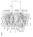
FIG. 1 is a sectional view of an eccentric oscillating gear device according to one embodiment of the present invention. -
FIG. 2 is a sectional view taken along the line II-II inFIG. 1 . -
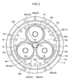
FIG. 3 is a view from the line III-III inFIG. 1 . -
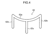
FIG. 4 is a perspective view of a temporary locking pin. -
FIGS. 5A to 5D are diagrams illustrating a rotational phase. - With reference to the drawings, the present invention will now be specifically described based on one embodiment thereof.
- As illustrated in
FIG. 1 , an eccentric oscillatinggear device 10 according to this embodiment comprises: anouter cylinder 12 serving as a first cylindrical section; acarrier 14 disposed inside theouter cylinder 12 to serve as a second cylindrical section adapted to be relatively rotatable with respect to theouter cylinder 12; aninput shaft 16 adapted to generate a rotational driving force for rotating thecarrier 14; and aspeed reduction mechanism 18 adapted to rotate thecarrier 14 at a rotation speed reduced at a given ratio with respect to a rotation speed of theinput shaft 16. Thegear device 10 is designed to transmit driving force while changing a rotation speed at a given rotation speed ratio, between afirst arm 20 serving as a first member, and asecond arm 38 serving as a second member. For example, thegear device 10 is configured as a speed reducer for use in an articulated joint for robot arms. - The
outer cylinder 12 is formed in a cylindrical shape, and an inner peripheral surface of theouter cylinder 12 has a large number ofpin grooves 12c formed at even intervals in a circumferential direction thereof. As also illustrated inFIG. 2 , a pin-shapedinternal tooth 24 is fitted in each of thepin grooves 12c. In other words, in this embodiment, theouter cylinder 12 serving as the first cylindrical section hasinternal teeth 24. - The
outer cylinder 12 has an outer peripheral portion integrally provided with aflange 12a. Theflange 12a has a plurality of bolt-insertion holes 12b provided at even intervals in a circumferential direction thereof. In this embodiment, the bolt-insertion hole 12b is provided in a number of eight. Theouter cylinder 12 and thefirst arm 20 are fastened together by inserting a plurality ofbolts 21 in respective ones of the bolt-insertion holes 12b, and screwing the insertedbolts 21 with respective ones of a plurality ofscrew holes 20c of thefirst arm 20. One of axially opposite ends (inFIG. 1 , a right end) of theouter cylinder 12 is closed by thefirst arm 20. Amotor 22 serving as a driving source is fixed to thefirst arm 20 which has a drive-shaft insertion hole 20a formed to penetrate therethrough in a thickness direction thereof so as to allow adrive shaft 22a of themotor 22 to be inserted thereinto. - The
carrier 14 is supported by theouter cylinder 12 through a pair ofmain bearings 26 disposed in axially spaced-apart relation. Thus, thecarrier 14 is adapted to be rotatable concentrically with theouter cylinder 12. In other words, thecarrier 14 is adapted to be rotated about an axis O1 of theouter cylinder 12 and relatively with respect to theouter cylinder 12. Each of themain bearings 26 is composed of an angular ball bearing. - The
carrier 14 comprises a circular disk-shapedend plate portion 30 serving as a first side portion, a circular disk-shapedbase plate portion 32 serving as a second side portion, and ashaft portion 33 protrudingly provided on one surface of thebase plate portion 32. Theshaft portion 33 is integrally formed with thebase plate portion 32. As illustrated inFIG. 2 , theshaft portion 33 has a generally hexagonal shape in cross-section. In this embodiment, theshaft portion 33 is provided in a number of three, wherein the threeshaft portions 33 are arranged at even intervals in a circumferential direction of thebase plate portion 32. After a distal end face of theshaft portion 33 is brought into contact with theend plate portion 30, theshaft portion 33 is fastened to theend plate portion 30 by abolt 34. In this state, a space having a given width in the axial direction is defined between thebase plate portion 32 and theend plate portion 30. - The
shaft portion 33 is provided with a bolt-fastening hole 33a. Thebolt 34 is inserted into a bolt-insertion hole 30a of theend plate portion 30 from a side opposite to theshaft portion 33, and screwed with the bolt-fasteninghole 33a of theshaft portion 33. Further, apin 36 is provided to extend between theshaft portion 33 and theend plate portion 30 so as to position theend plate portion 30 with respect to thebase plate portion 32. Instead of being integrally formed with thebase plate portion 32, theshaft portions 33 may be integrally formed with theend plate portion 30. In this case, theshaft portions 33 will be fastened to thebase end portion 32. - The
base end portion 32 is attached to thesecond arm 38 as a counterpart member, through anend face 32c thereof on a side opposite to theend plate portion 30. Thesecond arm 38 is formed with a plurality of bolt-insertion holes 38a, and thebase plate portion 32 has a plurality offastening holes 32d formed at positions corresponding to respective ones of the bolt-insertion holes 38a. Thesecond arm 38 and thebase plate portion 32 are fastened together by inserting a plurality ofbolts 37 in respective ones of the bolt-insertion holes 38a of thesecond arm 38, and screwing the insertedbolts 37 with respective ones of thefastening holes 32d of thebase plate portion 32. Two or more (five) of thefastening holes 32d are disposed at even intervals to form a fastening-hole group. The fastening-hole group is provided in a number of three, wherein the three fastening-hole groups are disposed about the axis O1 at even intervals (seeFIG. 3 ). - As illustrated in
FIG. 1 , theend plate portion 30 and thebase plate portion 32 are formed, respectively, with a through-hole 30b and a through-hole 32a each penetrating through a central region thereof in the axial direction. Each of the through-holes input shaft 16 to be inserted thereinto. Theinput shaft 16 is inserted in the through-holes outer cylinder 12. - The
input shaft 16 has a base end coaxially joined to thedrive shaft 22a of themotor 22, and a distal end located within the through-hole 32a of thebase plate portion 32. The distal end of theinput shaft 16 is integrally provided with adrive gear 42 composed of an externally toothed gear. - The
speed reduction mechanism 18 comprises spur gears 44,crankshafts 46, and externally toothed gears (a first externallytoothed gear 48a and a second externallytoothed gear 48b) serving as gear members. Each of the first and second externallytoothed gears outer cylinder 12. Thespur gear 44 is splined to a base plate portion-side end of thecrankshaft 46, and meshed with thedrive gear 42 provided on theinput shaft 16. Thus, driving force is transmitted to thecrankshaft 46 through thespur gear 44, so that thecrankshaft 46 is interlocked with a rotation of theinput shaft 16. - The
crankshaft 46 is disposed parallel to theinput shaft 16. Thecrankshaft 46 is rotatably supported by theend plate portion 30 through a first crankshaft bearing 51, and rotatably supported by thebase plate portion 32 through a second crankshaft bearing 52. In other words, the first crankshaft bearing 51 is disposed between theend plate portion 30 and thecrankshaft 46, and the second crankshaft bearing 52 is disposed between thebase plate portion 32 and thecrankshaft 46. Each of the first andsecond crankshaft bearings - The
end plate portion 30 and thebase plate portion 32 are formed with a through-hole 30c and a through-hole 32b, respectively. The through-hole 30c (32b) is formed in a number of three, wherein the three through-holes 32c (32b) are arranged around the through-hole 30b (32a) at even intervals in a circumferential direction. Thecrankshaft 46 is provided in a number of three, wherein the threecrankshafts 46 are disposed at even intervals in the circumferential direction (seeFIG. 2 ), while penetrating through respective paired ones of the through-holes - The
crankshaft 46 has ashaft body 46c, and eccentric portions (a firsteccentric portion 46a and a secondeccentric portion 46b) integrally formed on theshaft body 46c. Theshaft body 46c has a cross-sectionally circular shape, and each of the first and secondeccentric portions shaft body 46c. The first and secondeccentric portions eccentric portion 46a with respect to the crankshaft axis O2 and an eccentric direction of the secondeccentric portion 46b with respect to the crankshaft axis O2 are different from each other, and the respective phase angles of the first and secondeccentric portions crankshafts 46 are assembled to allow respective eccentric directions of the firsteccentric portions 46a thereof to coincide with each other. - The first and second
eccentric portions second crankshaft bearings eccentric portion 46a is disposed adjacent to the first crankshaft bearing 51, and the secondeccentric portion 46b is disposed adjacent to the second crankshaft bearing 52. - Each of the first externally
toothed gear 48a and the second externallytoothed gear 48b is disposed within the space between thebase plate portion 32 and theend plate portion 30. As also illustrated inFIG. 2 , each of the first and second externallytoothed gears hole 48c for allowing theinput shaft 16 to penetrate therethrough, a second through-hole 48d for allowing each of theshaft portions 33 to penetrate therethrough, and a third through-hole 48e for allowing the first and secondeccentric portions crankshafts 46 to penetrate therethrough. - A
roller bearing 55 is attached to each of the first and secondeccentric portions eccentric portion 46a is inserted in the third through-hole 48e of the first externallytoothed gear 48a, and the secondeccentric portion 46b is inserted in the third through-hole 48e of the second externallytoothed gear 48b. According to oscillating movements of the first and secondeccentric portions crankshaft 46, the first and second externallytoothed gears 48b are rotated while being meshed with theinternal teeth 24 of theouter cylinder 12. In this embodiment, the gear device is designed such that the externally toothed gear is provided in a number of two. Alternatively, the gear device may be designed such that the externally toothed gear is provided in a number of one or in a number of three or more. - As illustrated in
FIGS. 1 and3 , the through-hole 32a and the three through-holes 32b of thebase plate portion 32 are communicated with each other, i.e., formed as a single through-hole, in theend face 32c on the side opposite to theend plate portion 30. Thespur gear 44 is located within the single through-hole at a position corresponding to each of the through-holes 32b. Thus, when thebase plate portion 32 is detached from thesecond arm 38, oneprincipal surface 44a of thespur gear 44 is exposed. - As illustrated in
FIG. 3 , the eccentricoscillating gear device 10 is provided with rotational phase adjusting means 58 for setting an orientation of thecrankshaft 46 about the axis thereof, on the basis of orientations of theouter cylinder 12 and thecarrier 14 about the axis thereof. The rotational phase adjusting means 58 comprises afirst reference portion 58a, asecond reference portion 58b and athird reference portion 58c. - The
first reference portion 58a is provided in theouter cylinder 12 at a given position offset from the axis O1. In this embodiment, thefirst reference portion 58a is composed of a hole formed in theflange 12a of theouter cylinder 12. Thefirst reference portion 58a is provided in a number of one, wherein the onefirst reference portion 58a is formed at a position to be aligned with apin hole 20b (seeFIG. 1 ) of thefirst arm 20 when theflange 12a is fastened to thefirst arm 20. - As mentioned above, the plurality of bolt-
insertion holes 12b are formed in theflange 12a at even intervals in the circumferential direction of theflange 12a. Thus, as long as each of the bolt-insertion holes 12b is alignable with a respective one of the screw holes 20c of thefirst arms 20, a circumferential orientation of theouter cylinder 12 can be variously set with respect to thefirst arm 20. However, based on providing thefirst reference portion 58a, an orientation of theouter cylinder 12 about the axis O1 is fixed. Specifically, when thefirst reference portion 58a is aligned with thepin hole 20b formed in thefirst arm 20, the orientation of theouter cylinder 12 about the axis thereof is set to a given state with respect to thefirst arm 20. In this state, theouter cylinder 12 is fixedly attached to thefirst arm 20. Further, respective circumferential positions of thepin grooves 12c with respect to thefirst arm 20 are also set. - A pin (position adjustment member) 60 (see
FIG. 1 ) may be inserted to extend between thefirst reference portion 58a and thepin hole 20b of thefirst arm 20 so as to reliably perform the position adjustment. After completion of the position adjustment, thepin 60 may be detached. - Alternatively, the bolt-
insertion holes 12b formed in theflange 12a in the circumferential direction thereof may be intentionally arranged at uneven intervals so as to allow the circumferential orientation of theouter cylinder 12 with respect to thefirst arm 20 to be set only in a single way. In this case, the bolt-insertion holes 12b arranged at uneven intervals are used as thefirst reference portion 58a. - The
second reference portion 58b is provided in thecarrier 14 at a given position offset from the axis O1. In this embodiment, thesecond reference portion 58b is composed of a hole formed in theend face 32c of thebase plate portion 32 of thecarrier 14 on the side of the spur gears 44. More specifically, thesecond reference portion 58b is provided in theend face 32c of thebase plate portion 32 which faces thesecond arm 38. Thesecond reference portion 58b is provided in a number of one, wherein the onesecond reference portion 58b is formed at a position to be aligned with apin hole 38b (seeFIG. 1 ) of thesecond arm 38 when thebase plate portion 32 of thecarrier 14 is fastened to thesecond arm 38. - As mentioned above, the plurality of
fastening holes 32d are formed in thebase plate portions 32 in the circumferential direction thereof. Thus, as long as each of thefastening holes 32d is alignable with a respective one of the bolt-insertion hole 38a of thesecond arms 38, a circumferential orientation of the base plate portion 32 (carrier 14) can be variously set with respect to thesecond arm 38. However, based on providing thesecond reference portion 58b, an orientation of the base plate portion 32 (carrier 14) about the axis thereof is specified. - When the
second reference portion 58b is aligned with thepin hole 38b formed in thesecond arm 38, the orientation of thecarrier 14 about the axis thereof is set to a given state with respect to thesecond arm 38. In this state, thecarrier 14 is fixedly attached to thesecond arm 38. A temporary locking pin 62 (seeFIGS. 3 and4 ) may be inserted to extend between thesecond reference portion 58b and thepin hole 38b of thesecond arm 38 so as to reliably perform the position adjustment. After the position adjustment is completed by fixedly attaching thecarrier 14 to thesecond arm 38, thetemporary locking pin 62 may be detached. - Alternatively, the
fastening holes 32d formed in thebase plate portion 32 in the circumferential direction thereof may be arranged in a specific pattern so as to allow the circumferential orientation of the base plate portion 32 (carrier 14) with respect to thesecond arm 38 to be set only in a single way. In this case, thefastening holes 32d formed in thebase plate portion 32 are used as thesecond reference portion 58b. - The
temporary locking pin 62 is formed as a three-forked pin which comprises apin body 62a formed in an arc shape,legs 62b each extending from a respective one of opposite ends of thepin body 62a, and aleg 62c extending from an intermediate portion of thepin body 62a. Theleg 62c extending from the intermediate portion is adapted to be insertable into thepin hole 38b of thesecond arm 38 and thesecond reference portion 58b of thecarrier 14. - The
third reference portion 58c is provided in thespur gear 44 at a given position offset from the crankshaft axis O2. Thethird reference portion 58c is provided in each of the threespur gears 44, wherein each of thethird reference portions 58c is set at a position where it has a given directional relation with the eccentric directions of the first and secondeccentric portions crankshaft 46. In other words, each of thethird reference portions 58c has the same positional relationship with a corresponding one of the crankshaft axes O2. For example, thethird reference portion 58c may be formed in a direction coinciding with the eccentric direction of the secondeccentric portion 46b. Alternatively, as long as a positional relationship with each of the first and secondeccentric portions third reference portion 58c may be formed at any position. - The
third reference portion 58c is composed of a hole formed in theprincipal surface 44a of thespur gear 44. Theprincipal surface 44a is exposed when thesecond arm 38 is detached. Specifically, thethird reference portion 58c is provided in thesurface 44a facing thesecond arm 38, as with thesecond reference portion 58b provided in theend face 32c of thebase plate portion 32 of thecarrier 14. One of thethird reference portions 58c is provided in a respective one of the spur gears 44. Each of thelegs 62b at the ends of thetemporary locking pin 62 is adapted to be insertable into thethird reference portion 58c under a condition that themiddle leg 62c of thetemporary locking pin 62 is inserted into thesecond reference portion 58b of thecarrier 14 as mentioned above. - The
temporary locking pin 62 is not limited to the three-forked type. For example, a two-forkedtemporary locking pin 62 formed by omitting one of theend legs 62b may be employed. In this case, one 62c of two legs of thetemporary locking pin 62 is inserted into thesecond reference portion 58b, and theother leg 62b is inserted into thethird reference portion 58c. Further, in this case, an additional temporary locking pin (illustration is omitted) may be used to, after positioning one of the three spur gears 44 (or crankshaft 46) with respect to thecarrier 14, position the remaining two spur gears 44 (or two crankshafts 46) with respect to the positionedspur gear 44. In this case, the additional temporary locking pin may have apin body 62a formed in a triangular shape to allow three legs thereof to be simultaneously inserted into respective ones of thethird reference portions 58c. - Alternatively, a temporary locking pin (illustration is omitted) for positioning the
second reference portion 58b with respect to thesecond arm 38, and a temporary locking pin (illustration is omitted) for positioning the spur gear 44 (crankshaft 46) with respect to thecarrier 14, may be formed as separate pins. In this case, the temporary locking pin for positioning thecarrier 14 with respect to thesecond arm 38 may be composed of a rod-like pin. This rod-like pin may be used without being detached. - An operation of the eccentric
oscillating gear device 10 according to this embodiment will be briefly described below. In thegear device 10, theinput shaft 16 is driven by driving force of themotor 22, and, according to a resulting rotation of theinput shaft 16, the spur gears 44 are rotated through thedrive gear 42. Thus, each of thecrankshafts 46 is rotated together with a corresponding one of the spur gears 44. Upon rotation of thecrankshaft 46, according to an oscillating movement of the firsteccentric portion 46a, the first externallytoothed gear 48a is rotated while being meshed with theinternal teeth 24. Further, according to an oscillating movement of the secondeccentric portion 46b, the second externallytoothed gear 48b is rotated while being meshed with theinternal teeth 24. Thus, thecarrier 14 having theshaft portions 33 each penetrating through the second through-holes 48d of the first and second externallytoothed gears second arm 38 is relatively rotated with respect to thefirst arm 20. A rotation speed of the second arm 38 (carrier 14) has a value which is reduced at a given ratio with respect to a rotation speed input into theinput shaft 16. - A reason for adjusting a rotational phase of the
crankshaft 46 with respect to theouter cylinder 12 and thecarrier 14 will be described below.FIG. 5A is a schematic diagram illustrating a positional relationship between respective ones of thefirst reference portion 58a representing a reference point of theouter cylinder 12, thesecond reference portion 58b representing a reference point of thecarrier 14, and thethird reference portion 58c representing a reference point of thecrankshaft 46.FIG. 5B schematically illustrates a position of thefirst reference portion 58a on thefirst arm 20, and a position of thesecond reference portion 58b on thesecond arm 38.FIGS. 5A and 5B illustrate a state when theouter cylinder 12, thecarrier 14, and each of thecrankshafts 46, are set to a given orientation about the axis O1 with respect to thefirst arm 20, a given orientation about the axis O1 with respect to thesecond arm 38, and a given orientation about the crankshaft axis O2, respectively. The solid line illustrated inFIG. 5C indicates torsional rigidity in a rotation direction when thecarrier 14 in the above state is rotated about the axis O1 relatively with respect to theouter cylinder 12. The torsional rigidity is periodically changed. This is caused, for example, by a difference in circumferential weight of thecarrier 14 about the axis O1 (e.g., a difference in weight between portions with and without the through-holes crankshaft 46 about the crankshaft axis O2. -
FIG. 5D illustrates a state when thesecond reference portion 58b is displaced about the axis O1 from the position illustrated inFIG. 5A by about 30 degrees, and thethird reference portion 58c is rotated about the crankshaft axis O2 with respect to thecarrier 14. For example,FIG. 5D may be assumed to be in a state when the gear device assembled as illustrated inFIG. 5A is disassembled for maintenance or the like and then re-assembled. - The solid line in
FIG. 5C indicates torsional rigidity occurring when thecarrier 14 is rotated from the position illustrated inFIG. 5A , and the broken line inFIG. 5C indicates torsional rigidity occurring when thecarrier 14 is rotated from the position illustrated inFIG. 5D . As is clear fromFIG. 5C , the torsional rigidity becomes different between when an initial setting is performed in a coupled state between the first andsecond arms FIG. 5A and when the initial setting is performed in a coupled state between the first andsecond arms FIG. 5D , even if thesecond arm 38 is located at the same position with respect to thefirst arm 20. Thus, if a rotational position adjustment between respective ones of the five components: thefirst arm 20, thesecond arm 38, theouter cylinder 12, thecarrier 14 and thecrankshaft 46, is not performed, the torsional rigidity at an initial set position is changed, so that it is necessary to perform a fine adjustment by means of teaching. Therefore, the rotational phase adjustment between respective ones of the five components can be performed to reduce a variation in torsional rigidity. In the above description, the reason for a variation in torsional rigidity has been explained by taking a variation in orientation of thecarrier 14 with respect to theouter cylinder 12 as an example. However, the variation in torsional rigidity is also caused by a difference in orientation (eccentric direction) of thecrankshaft 46 with respect to theouter cylinder 12, and by a difference in orientation (eccentric direction) of thecrankshaft 46 with respect to thecarrier 14. Thus, it is necessary to adjust orientations between respective ones of theouter cylinder 12, thecarrier 14 and thecrankshaft 46. - A process of assembling the
crankshaft 46 in the eccentricoscillating gear device 10 will be briefly described below. In the process of assembling thecrankshaft 46, thecrankshaft 46 provided with the first and secondeccentric portions spur gear 44 is first assembled to thecarrier 14. In this assembling step, thetemporary locking pin 62 is inserted into thesecond reference portion 58b and thethird reference portion 58c to set an orientation of thecrankshaft 46 about the axis thereof with respect to thecarrier 14. In conjunction with the setting of the orientation of thecrankshaft 46 with respect to thecarrier 14, thecarrier 14 may be positioned with respect to thesecond arm 38. Alternatively, thecarrier 14 may be subsequently positioned with respect to thesecond arm 38. - Then, the
carrier 14 is assembled to theouter cylinder 12. In this assembling step, thefirst reference portion 58a and thesecond reference portion 58b are used to set an orientation of thecarrier 14 about the axis thereof with respect to theouter cylinder 12. In this case, a positional relationship between thefirst reference portion 58a and thesecond reference portion 58b may be set to a given state on a visual basis, or using a two-forked temporary locking pin. Thus, an orientation of thecrankshaft 46 about the crankshaft axis O2 is set on the basis of the orientations of theouter cylinder 12 and thecarrier 14 about the axis O1. Then, thefirst arm 20 and thesecond arm 38 are fastened to the gear device using thepin 60 and thetemporary locking pin 62. This makes it possible to establish a coupled state between the first andsecond arms outer cylinder 12 with respect to thefirst arm 20, the orientation of thecarrier 14 with respect to thesecond arm 38, and the orientation of thecrankshaft 46 with respect to theouter cylinder 12 and thecarrier 14, are set. - As described above, the eccentric oscillating gear device according to the above embodiment is capable of setting an orientation of the
crankshaft 46 about the axis thereof, on the basis of orientations of theouter cylinder 12 and thecarrier 14 about the axis thereof. Thus, when theouter cylinder 12 and thecarrier 14 are attached, respectively, to thefirst arm 20 and thesecond arm 38, an orientation of thecrankshaft 46 with respect to thefirst arm 20 and thesecond arm 38 can be set through the orientations of theouter cylinder 12 and thecarrier 14. In other words, the orientation of thecrankshaft 46 can be set using the rotational phase adjusting means. Thus, in cases where thegear device 10 is disassembled during maintenance or the like and then re-assembled, it becomes possible to prevent a phase of torsional rigidity in a rotation direction from being changed from that before the disassembling. Further, it becomes possible to prevent an individual difference in phase of the torsional rigidity in the rotation direction from occurring between respective ones of a plurality of thegear devices 10. - In the above embodiment, in an operation of assembling the
crankshaft 46, thecrankshaft 46 is assembled to allow thethird reference portion 58c to be set to a given position on the basis of thefirst reference portion 58a and thesecond reference portion 58b. Thus, thecrankshaft 46 can be assembled such that an orientation thereof is set to a given state on the basis of the orientations of theouter cylinder 12 and thecarrier 14 about the axis thereof. - In the above embodiment, during assembling of the
crankshaft 46, a two-forked or three-forkedtemporary locking pin 62 is inserted to extend between thesecond reference portion 58b and thethird reference portion 58c each composed of a hole, so that it becomes possible to reliably set an orientation of thecrankshaft 46 with respect to thecarrier 14. When thetemporary locking pin 62 is subsequently detached, an eccentricoscillating gear device 10 can be provided in which thecrankshaft 46 is assembled to thecarrier 14 under a condition that the orientation of thecrankshaft 46 is adjusted to a given state. - The present invention is not limited to the above embodiment, but various changes and modifications may be made therein without departing from the spirits and scope of the present invention. For example, although the above embodiment has been described based on an example where each of the first, second and
third reference portions third reference portions - Although the gear device according to the above embodiment is designed such that the
third reference portion 58c is provided in thespur gear 44, the present invention is not limited thereto. For example, thethird reference portion 58c may be provided in any other suitable portion viewable from the side of thesecond arm 38, such as an end face of thecrankshaft 46 on the side of thesecond arm 38. Alternatively, thethird reference portion 58c may be provided in any other suitable portion viewable from the side of thefirst arm 20, such as an end face of thecrankshaft 46 on the side of thefirst arm 20. - The gear device according to the above embodiment is designed such that the
spur gear 44 is joined to the end of thecrankshaft 46. Alternatively, thespur gear 44 may be disposed between the firsteccentric portion 46a and the secondeccentric portion 46b. In this case, thethird reference portion 58c may be provided in an end face of thecrankshaft 46 or an end face of the secondeccentric portion 46b, as well as the oneprincipal surface 44a of thespur gear 44. - Although the gear device according to the above embodiment is designed such that the plurality of
crankshafts 46 are arranged at positions offset from the axis O1 of theouter cylinder 12 at even intervals in the circumferential direction, the present invention is not limited thereto. For example, a so-called "center crank mechanism" may be employed in which asingle crankshaft 46 is disposed in concentric relation with theouter cylinder 12 and thecarrier 14. In this case, thethird reference portion 58c may be provided in a spur gear joined to thecrankshaft 46. Further, in a structure where a spur gear is omitted, thethird reference portion 58c may be formed in a distal end face of thecrankshaft 46. - In the above embodiment, in an operation of adjusting a rotational phase of the
gear device 10, thetemporary locking pin 62 is inserted into thesecond reference portion 58b provided in thecarrier 14, thethird reference portion 58c provided in thespur gear 44 and thepin hole 38b provided in thesecond arm 38 to adjust the rotational phase. Alternatively, the rotational phase of thegear device 10 may be adjusted before the assembling to thesecond arm 38. For example, thetemporary locking pin 62 is inserted into thesecond reference portion 58b and thethird reference portion 58c from the side of one end (inFIG. 1 , a left end) of thegear device 10 to adjust rotational phases of thecarrier 14 and thecrankshaft 46. In this state, thegear device 10 is assembled to thefirst arm 20 while adjusting the rotational phase thereof using thefirst reference portion 58a. Then, themotor 22 is attached to thefirst arm 20 from the side of the other end (inFIG. 1 , a right end) of thegear device 10, and thedrive gear 42 of theinput shaft 16 is meshed with thespur gear 44. Then, the motor is powered on to allow a reference rotational phase to be recognized by a servo lock function, a brake attached to the motor or the like, and fixed. Then, the temporary locking pin is detached from the gear device. Even if the temporary locking pin is detached, thecarrier 14 and thecrankshaft 46 are kept from rotating, for example, by the servo lock function. Finally, thegear device 10 is attached to thesecond arm 38 while adjusting respective positions of thesecond arm 38 and thefirst arm 20. - Although the above embodiment has been described based on a structure comprising the
outer cylinder 12 provided with theinternal teeth 24, and the first and second externallytoothed gears JP 2000-065158A - In the above embodiment, the outer cylinder is formed to serve as an example of the first cylindrical section, and the carrier is formed to serve as an example of the second cylindrical section. Alternatively, the carrier may be formed to serve as an example of the first cylindrical section, and the outer cylinder may be formed to serve as an example of the second cylindrical section.
- An outline of the above embodiment will be described below.
- (1) The eccentric oscillating gear device according to the above embodiment is provided with rotational phase adjusting means for setting an orientation of the crankshaft about an axis thereof, on the basis of orientations of the first and second cylindrical sections about an axis thereof. This makes it possible to set the orientation of the crankshaft about the axis thereof, on the basis of the orientations of the first and second cylindrical sections about the axis thereof. Thus, when the first cylindrical section and the second cylindrical section are attached, respectively, to a first member and a second member, an orientation of the crankshaft with respect to the first member and the second member can be set through the orientations of the first and second cylindrical sections. Thus, in cases where the gear device is disassembled during maintenance or the like and then re-assembled, it becomes possible to prevent a phase of torsional rigidity in a rotation direction from being changed from that before the disassembling. Further, it becomes possible to prevent an individual difference in phase of the torsional rigidity in the rotation direction from occurring between respective ones of a plurality of the gear devices.
- (2) Preferably, the rotational phase adjusting means has a first reference portion provided in the first cylindrical section at a given position offset from the axis thereof, a second reference portion provided in the second cylindrical section at a given position offset from the axis thereof, and a third reference portion provided in the crankshaft or in a spur gear joined to the crankshaft, at a given position offset from the axis of the crankshaft.
- According to this feature, in an operation of assembling the crankshaft, the crankshaft is assembled to allow the third reference portion to be set to a given position on the basis of the first reference portion and the second reference portion, so that the crankshaft can be assembled such that an orientation thereof is set to a given state on the basis of the orientations of the first and second cylindrical sections about the axis thereof.
- (3) Each of the second and third reference portion may be formed as a hole.
- According to this feature, during assembling of the crankshaft, a two-forked or three-forked temporary locking pin is inserted to extend between the second reference portion and the third reference portion each composed of a hole, so that it becomes possible to reliably set an orientation of the crankshaft with respect to the carrier. When the temporary locking pin is subsequently detached, an eccentric oscillating gear device can be provided in which the crankshaft is assembled to the first or second cylindrical section under a condition that the orientation of the crankshaft is adjusted to a given state.
- (4) The crankshaft may be provided in a number of one. In this case, the one crankshaft may be disposed in concentric relation with respect to the first or second cylindrical section.
- (5) The crankshaft may be provided in a number of two or more. In this case, the two or more crankshafts may be disposed about the axis of the first or second cylindrical section at even intervals.
- (6) One of the first and second cylindrical sections may be a carrier, and a remaining one of the first and second cylindrical sections may be an outer cylinder having internal teeth. In this case, the gear member may be an externally toothed gear meshed with the internal teeth of the outer cylinder.
- (7) One of the first and second cylindrical sections may be an outer cylinder, and a remaining one of the first and second cylindrical sections may be a carrier having external teeth. In this case, the gear member may be an internally toothed gear meshed with the external teeth of the carrier.
- As mentioned above, the eccentric oscillating gear device according to the above embodiment is capable of reducing a variation in torsional rigidity in a rotation direction.
-
- 12:
- outer cylinder
- 14:
- carrier
- 24:
- internal teeth
- 30:
- end plate portion
- 32:
- base plate portion
- 46:
- crankshaft
- 46a:
- first eccentric portion
- 46b:
- second eccentric portion
- 48a:
- first externally toothed gear
- 48b:
- second externally toothed gear
- 48e:
- third through-hole
- 58:
- rotational phase adjusting means
- 58a:
- first reference portion
- 58b:
- second reference portion
- 58c:
- third reference portion
Claims (8)
- An eccentric oscillating gear device for transmitting driving force while changing a rotation speed at a given rotation speed ratio between a first member and a second member, comprising:a crankshaft having an eccentric portion;a gear member having a tooth portion and a through-hole in which the eccentric portion is inserted;a first cylindrical section adapted to be attachable to one of the first and second members; anda second cylindrical section adapted to be attachable to a remaining one of the first and second members,wherein:one of the first and second cylindrical sections rotatably supports the crankshaft;a remaining one of the first and second cylindrical sections has a tooth portion meshed with the tooth portion of the gear member;the first and second cylindrical sections are adapted to be rotatable concentrically and relatively with respect to each other according to an oscillating movement of the gear member along with a rotation of the crankshaft,and wherein the eccentric oscillating gear device is provided with rotational phase adjusting means for setting an orientation of the crankshaft about an axis thereof, on the basis of orientations of the first and second cylindrical sections about an axis thereof.
- The eccentric oscillating gear device as defined in claim 1, wherein the rotational phase adjusting means has a first reference portion provided in the first cylindrical section at a given position offset from the axis thereof, a second reference portion provided in the second cylindrical section at a given position offset from the axis thereof, and a third reference portion provided in the crankshaft or in a spur gear joined to the crankshaft, at a given position offset from the axis of the crankshaft.
- The eccentric oscillating gear device as defined in claim 2, wherein each of the second and third reference portion is formed as a hole.
- The eccentric oscillating gear device as defined in any one of claims 1 to 3, wherein the crankshaft is provided in a number of one, and is disposed in concentric relation with respect to the first or second cylindrical section.
- The eccentric oscillating gear device as defined in any one of claims 1 to 3, wherein the crankshaft is provided in a number of two or more, and wherein the two or more crankshafts are disposed about the axis of the first or second cylindrical section at even intervals.
- The eccentric oscillating gear device as defined in any one of claims 1 to 5, wherein:one of the first and second cylindrical sections is a carrier;a remaining one of the first and second cylindrical sections is an outer cylinder having internal teeth; andthe gear member is an externally toothed gear meshed with the internal teeth of the outer cylinder.
- The eccentric oscillating gear device as defined in any one of claims 1 to 5, wherein:one of the first and second cylindrical sections is an outer cylinder;a remaining one of the first and second cylindrical sections is a carrier having external teeth; andthe gear member is an internally toothed gear meshed with the external teeth of the carrier.
- A method of assembling a crankshaft in an eccentric oscillating gear device for transmitting driving force while changing a rotation speed at a given rotation speed ratio between a first member and a second member, comprising the steps of:assembling a crankshaft having an eccentric portion to a gear member;assembling the crankshaft to one of a first cylindrical section and a second cylindrical section;assembling the gear member to a remaining one of the first and second members which has a tooth portion; andcombining the first and second cylindrical sections together,wherein:the step of assembling the crankshaft to one of the first cylindrical section and the second cylindrical section includes using rotational phase adjusting means to set an orientation of the crankshaft about an axis thereof, with respect to one of the first and second cylindrical sections; andthe step of combining the first and second cylindrical sections together includes using the rotational phase adjusting means to set an orientation of the second cylindrical section about an axis thereof, with respect to the first cylindrical section.
Priority Applications (1)
| Application Number | Priority Date | Filing Date | Title |
|---|---|---|---|
| EP13005819.1A EP2708772B1 (en) | 2009-06-15 | 2010-05-28 | Robot |
Applications Claiming Priority (2)
| Application Number | Priority Date | Filing Date | Title |
|---|---|---|---|
| JP2009142496A JP5270462B2 (en) | 2009-06-15 | 2009-06-15 | Eccentric oscillating gear device and crankshaft assembling method in eccentric oscillating gear device |
| PCT/JP2010/003614 WO2010146779A1 (en) | 2009-06-15 | 2010-05-28 | Eccentric rocking type gear device and assembling method for crank shaft in eccentric rocking type gear device |
Related Child Applications (2)
| Application Number | Title | Priority Date | Filing Date |
|---|---|---|---|
| EP13005819.1A Division EP2708772B1 (en) | 2009-06-15 | 2010-05-28 | Robot |
| EP13005819.1A Division-Into EP2708772B1 (en) | 2009-06-15 | 2010-05-28 | Robot |
Publications (3)
| Publication Number | Publication Date |
|---|---|
| EP2439426A1 true EP2439426A1 (en) | 2012-04-11 |
| EP2439426A4 EP2439426A4 (en) | 2013-01-02 |
| EP2439426B1 EP2439426B1 (en) | 2014-03-12 |
Family
ID=43356114
Family Applications (2)
| Application Number | Title | Priority Date | Filing Date |
|---|---|---|---|
| EP13005819.1A Active EP2708772B1 (en) | 2009-06-15 | 2010-05-28 | Robot |
| EP10789164.0A Active EP2439426B1 (en) | 2009-06-15 | 2010-05-28 | Eccentric oscillating gear device and assembling method for crankshaft in eccentric oscillating gear device |
Family Applications Before (1)
| Application Number | Title | Priority Date | Filing Date |
|---|---|---|---|
| EP13005819.1A Active EP2708772B1 (en) | 2009-06-15 | 2010-05-28 | Robot |
Country Status (6)
| Country | Link |
|---|---|
| US (2) | US8684879B2 (en) |
| EP (2) | EP2708772B1 (en) |
| JP (1) | JP5270462B2 (en) |
| KR (1) | KR101707054B1 (en) |
| CN (2) | CN102449347B (en) |
| WO (1) | WO2010146779A1 (en) |
Cited By (3)
| Publication number | Priority date | Publication date | Assignee | Title |
|---|---|---|---|---|
| DE102012014343A1 (en) * | 2011-07-20 | 2013-01-24 | Sumitomo Heavy Industries, Ltd. | Receptacle structure for a speed reduction gearbox, take-up method and speed-reduction gear of eccentric oscillating type. |
| CN107690534A (en) * | 2015-06-08 | 2018-02-13 | 世进Igb株式会社 | Internal planetary reduction gear |
| EP4056870A1 (en) * | 2021-03-11 | 2022-09-14 | Nabtesco Corporation | Speed reducer |
Families Citing this family (35)
| Publication number | Priority date | Publication date | Assignee | Title |
|---|---|---|---|---|
| JP2013096550A (en) * | 2011-11-04 | 2013-05-20 | Nabtesco Corp | Gear transmission device |
| JP5941349B2 (en) | 2012-06-25 | 2016-06-29 | ナブテスコ株式会社 | Eccentric oscillating gear unit |
| US8663049B1 (en) * | 2012-11-28 | 2014-03-04 | Tsun-Tien Yao | Speed reducer |
| JP5917421B2 (en) * | 2013-01-29 | 2016-05-11 | 住友重機械工業株式会社 | Series of eccentric oscillating speed reducers |
| JP6137875B2 (en) * | 2013-03-01 | 2017-05-31 | 住友重機械工業株式会社 | Planetary gear reducer |
| CN104100680B (en) * | 2013-04-12 | 2017-07-21 | 鸿富锦精密工业(深圳)有限公司 | Cycloidal planetary gear speed reducer structure |
| JP2015021554A (en) * | 2013-07-18 | 2015-02-02 | ナブテスコ株式会社 | Eccentric oscillation type gear device |
| JP2015083329A (en) * | 2013-10-25 | 2015-04-30 | 住友重機械工業株式会社 | Method for manufacturing eccentric oscillation type speed reducer |
| US9476484B2 (en) * | 2014-11-07 | 2016-10-25 | Andrew Duerner | Oscillatory gearbox |
| JP6376964B2 (en) | 2014-12-09 | 2018-08-22 | 住友重機械工業株式会社 | Reducer series, reducer series manufacturing method, reducer |
| JP6543463B2 (en) | 2014-12-25 | 2019-07-10 | ナブテスコ株式会社 | Design method of speed reducer group and speed reducer group |
| JP6441070B2 (en) | 2014-12-25 | 2018-12-19 | ナブテスコ株式会社 | Reduction gear design method |
| JP6542530B2 (en) | 2014-12-25 | 2019-07-10 | ナブテスコ株式会社 | Design method of speed reducer group and speed reducer group |
| JP6446260B2 (en) | 2014-12-25 | 2018-12-26 | ナブテスコ株式会社 | Reduction gear group, reduction gear and reduction gear design method |
| JP6542534B2 (en) | 2015-01-27 | 2019-07-10 | ナブテスコ株式会社 | Eccentric oscillating gear |
| JP6532739B2 (en) * | 2015-04-08 | 2019-06-19 | ナブテスコ株式会社 | Eccentric oscillating gear device and method for adjusting rigidity of eccentric oscillating gear device |
| US9562603B2 (en) * | 2015-06-29 | 2017-02-07 | Deere & Company | Drive assembly with a rotating housing attached to an output interface |
| US9638310B2 (en) | 2015-06-29 | 2017-05-02 | Deere & Company | Drive assembly with a rotating housing attached to an output interface |
| JP6681201B2 (en) * | 2016-01-22 | 2020-04-15 | ナブテスコ株式会社 | Steering device |
| JP6717619B2 (en) * | 2016-03-07 | 2020-07-01 | ナブテスコ株式会社 | Gear device |
| JP2016153696A (en) * | 2016-05-23 | 2016-08-25 | ナブテスコ株式会社 | Process of manufacture of gear transmission |
| JP6752070B2 (en) * | 2016-07-12 | 2020-09-09 | ナブテスコ株式会社 | Gear device |
| KR101805576B1 (en) * | 2016-09-01 | 2017-12-07 | 주식회사 세진아이지비 | Planetary reduction gear device for ultra high reduction gear ratio |
| CN106438866A (en) * | 2016-12-12 | 2017-02-22 | 重庆澜循科技有限公司 | Output mechanism of squirrel-cage type RV (rotate vector) reducer |
| EP3339235B1 (en) * | 2016-12-21 | 2020-06-03 | Otis Elevator Company | Self-locking gear and people conveyor comprising a self-locking gear |
| TWI636207B (en) * | 2017-04-19 | 2018-09-21 | 姚村田 | Speed reducer |
| US9752653B1 (en) * | 2017-04-28 | 2017-09-05 | Tsun-Tien Yao | Speed reducer with rollers |
| JP2017202565A (en) * | 2017-06-02 | 2017-11-16 | ナブテスコ株式会社 | Manufacturing method of gear transmission |
| US11359670B2 (en) * | 2018-06-12 | 2022-06-14 | Quanta Machinery Co., Ltd. | Transmission roller, and pin-teeth cycloid reducer with the same and bearing with the same |
| US10817809B2 (en) | 2018-07-27 | 2020-10-27 | Servicenow, Inc. | Systems and methods for customizable route optimization |
| CN109083984B (en) * | 2018-10-12 | 2024-07-23 | 珠海格力电器股份有限公司 | Speed reducer, speed reducing motor and robot |
| JP7139228B2 (en) * | 2018-11-22 | 2022-09-20 | 株式会社ユーシン | Gear device manufacturing method |
| JP7316828B2 (en) * | 2019-04-15 | 2023-07-28 | ナブテスコ株式会社 | Decelerator |
| CN110842499B (en) * | 2019-10-21 | 2025-03-25 | 广东顺德奥凯捷智能科技有限公司 | A compressor crankshaft parts assembly and thrust surface grinding production line |
| EP4067696B1 (en) * | 2021-03-31 | 2025-12-10 | Nabtesco Corporation | Drive transmission device and construction machine |
Family Cites Families (29)
| Publication number | Priority date | Publication date | Assignee | Title |
|---|---|---|---|---|
| JPS5942347U (en) * | 1982-09-13 | 1984-03-19 | 有限会社日本興産 | planetary differential reducer |
| JPS6020384B2 (en) | 1983-03-11 | 1985-05-21 | 株式会社ネオス | Method for producing fluorine-containing pyridinium salt |
| JPH02138538A (en) * | 1988-11-18 | 1990-05-28 | Komatsu Ltd | reduction gear |
| US5123882A (en) * | 1991-10-10 | 1992-06-23 | Trogetec, Inc. | Compound planocentric cycloidal gear drives with orthogonal planet arrangements |
| CN2284883Y (en) * | 1996-07-12 | 1998-06-24 | 陈智 | Full rolling moving gear |
| JP3712515B2 (en) * | 1997-12-11 | 2005-11-02 | ナブテスコ株式会社 | Planetary gear set |
| JP3919349B2 (en) | 1998-08-21 | 2007-05-23 | 住友重機械工業株式会社 | Internal gear swing type intermeshing planetary gear unit |
| JP3545995B2 (en) * | 2000-06-12 | 2004-07-21 | ファナック株式会社 | Robot joint structure |
| JP4768153B2 (en) * | 2001-06-29 | 2011-09-07 | ヤマハ発動機株式会社 | Two-stage gear assembly jig |
| ATE514014T1 (en) * | 2001-08-23 | 2011-07-15 | Sew Eurodrive Gmbh & Co | TRANSMISSION SERIES |
| JP4004256B2 (en) | 2001-09-13 | 2007-11-07 | ナブテスコ株式会社 | Eccentric rocking speed reducer |
| JP2003262256A (en) * | 2002-03-08 | 2003-09-19 | Sumitomo Heavy Ind Ltd | Internal planetary gear device and method for attaching external tooth gear |
| JP4878430B2 (en) * | 2002-08-05 | 2012-02-15 | 住友重機械工業株式会社 | Sliding structure of rotating body and rocking body |
| JP4167879B2 (en) * | 2002-10-15 | 2008-10-22 | 住友重機械工業株式会社 | Decelerator |
| JP2004286044A (en) * | 2003-03-19 | 2004-10-14 | Sumitomo Heavy Ind Ltd | Internal gear swing type inner mesh planetary gear |
| JP4726185B2 (en) * | 2004-01-13 | 2011-07-20 | ナブテスコ株式会社 | Eccentric oscillating gear unit |
| EP2463548B1 (en) * | 2004-01-30 | 2013-08-21 | Nabtesco Corporation | Eccentric oscillating-type planetary gear device |
| US20080295623A1 (en) * | 2004-08-11 | 2008-12-04 | Nabtesco Corporation | Speed Reducer to be Attached to Articulated Portion Industrial Robot |
| JP4901156B2 (en) * | 2005-08-11 | 2012-03-21 | ナブテスコ株式会社 | Reduction gear |
| JP4762643B2 (en) | 2005-08-22 | 2011-08-31 | ナブテスコ株式会社 | Center crank type eccentric oscillating speed reducer |
| JP2007085530A (en) * | 2005-09-26 | 2007-04-05 | Nabtesco Corp | Hollow reducer |
| CN101375083B (en) * | 2006-01-26 | 2012-10-17 | 纳博特斯克株式会社 | Reducer |
| JP2007247730A (en) | 2006-03-15 | 2007-09-27 | Nabtesco Corp | Gear reducer and joint structure of industrial robot provided with the gear reducer |
| JP4818787B2 (en) * | 2006-04-17 | 2011-11-16 | 住友重機械工業株式会社 | Swing intermeshing planetary gear unit |
| EP2014949A1 (en) * | 2006-04-28 | 2009-01-14 | Nabtesco Corporation | Reduction gear mechanism, and its manufacturing method |
| EP2077404A1 (en) * | 2006-09-01 | 2009-07-08 | Nabtesco Corporation | Reduction gear |
| JP4847892B2 (en) * | 2007-02-22 | 2011-12-28 | 住友重機械工業株式会社 | Oscillating intermeshing planetary gear device and manufacturing method of eccentric shaft thereof |
| JP2008286409A (en) * | 2008-09-04 | 2008-11-27 | Nabtesco Corp | Eccentric rocking speed reducer |
| JP2012197916A (en) * | 2011-03-23 | 2012-10-18 | Seiko Epson Corp | Speed reducer, robot hand and robot |
-
2009
- 2009-06-15 JP JP2009142496A patent/JP5270462B2/en active Active
-
2010
- 2010-05-28 EP EP13005819.1A patent/EP2708772B1/en active Active
- 2010-05-28 WO PCT/JP2010/003614 patent/WO2010146779A1/en not_active Ceased
- 2010-05-28 EP EP10789164.0A patent/EP2439426B1/en active Active
- 2010-05-28 CN CN201080023371.1A patent/CN102449347B/en active Active
- 2010-05-28 KR KR1020117031310A patent/KR101707054B1/en active Active
- 2010-05-28 US US13/375,335 patent/US8684879B2/en active Active
- 2010-05-28 CN CN201410460856.7A patent/CN104389957B/en active Active
-
2014
- 2014-02-12 US US14/178,599 patent/US9097322B2/en active Active
Non-Patent Citations (2)
| Title |
|---|
| No further relevant documents disclosed * |
| See also references of WO2010146779A1 * |
Cited By (7)
| Publication number | Priority date | Publication date | Assignee | Title |
|---|---|---|---|---|
| DE102012014343A1 (en) * | 2011-07-20 | 2013-01-24 | Sumitomo Heavy Industries, Ltd. | Receptacle structure for a speed reduction gearbox, take-up method and speed-reduction gear of eccentric oscillating type. |
| CN107690534A (en) * | 2015-06-08 | 2018-02-13 | 世进Igb株式会社 | Internal planetary reduction gear |
| EP3306133A4 (en) * | 2015-06-08 | 2018-05-30 | Sejin-igb Co., Ltd. | Internal planetary reduction gear |
| US20180149237A1 (en) * | 2015-06-08 | 2018-05-31 | Sejin-iGB Co., Ltd. | Internal planetary reduction gear |
| US10378614B2 (en) | 2015-06-08 | 2019-08-13 | Sejin-iGB Co., Ltd. | Internal planetary reduction gear |
| CN107690534B (en) * | 2015-06-08 | 2020-05-05 | 世进Igb株式会社 | Internal planetary reduction gear |
| EP4056870A1 (en) * | 2021-03-11 | 2022-09-14 | Nabtesco Corporation | Speed reducer |
Also Published As
| Publication number | Publication date |
|---|---|
| WO2010146779A1 (en) | 2010-12-23 |
| JP2010286098A (en) | 2010-12-24 |
| CN104389957A (en) | 2015-03-04 |
| CN102449347A (en) | 2012-05-09 |
| EP2708772A2 (en) | 2014-03-19 |
| KR101707054B1 (en) | 2017-02-15 |
| US20120108381A1 (en) | 2012-05-03 |
| JP5270462B2 (en) | 2013-08-21 |
| KR20120037416A (en) | 2012-04-19 |
| EP2439426B1 (en) | 2014-03-12 |
| EP2708772A3 (en) | 2014-08-13 |
| US20140171250A1 (en) | 2014-06-19 |
| CN104389957B (en) | 2017-04-26 |
| CN102449347B (en) | 2014-10-22 |
| US9097322B2 (en) | 2015-08-04 |
| EP2439426A4 (en) | 2013-01-02 |
| EP2708772B1 (en) | 2019-01-09 |
| US8684879B2 (en) | 2014-04-01 |
Similar Documents
| Publication | Publication Date | Title |
|---|---|---|
| EP2439426B1 (en) | Eccentric oscillating gear device and assembling method for crankshaft in eccentric oscillating gear device | |
| US8162789B2 (en) | Reduction gear box | |
| KR101258241B1 (en) | Hollow reduction gear | |
| US8047943B2 (en) | Reduction gear transmission | |
| CN102483132B (en) | Eccentric oscillating gear device and method for manufacturing eccentric oscillating gear device | |
| JP2010065803A (en) | Eccentrically oscillating gear device | |
| JP2010014177A (en) | Eccentric rocking type gear transmission device | |
| JP2007078010A (en) | Industrial robot swivel structure | |
| JP5799072B2 (en) | robot | |
| JP2013185650A (en) | Eccentric swing gear device | |
| JPH05296301A (en) | Planetary gear type reduction gear with backlashless mechanism | |
| EP4198340B1 (en) | Eccentric oscillation gear device and robot | |
| JP2011185367A (en) | Member connecting structure and gear device | |
| RU2244181C2 (en) | Planet gear | |
| JP2013185631A (en) | Eccentric swing gear device | |
| US11603908B2 (en) | Speed reducer and eccentric gear of the same | |
| US8881701B2 (en) | Camshaft adjusting device | |
| JP4632852B2 (en) | Industrial robot swivel structure | |
| JP2006297558A (en) | Industrial robot swivel structure | |
| JPH04282046A (en) | Trochoid-system tooth profile internal contact type planetary gear structure | |
| RU2270949C1 (en) | Rotatable reduction gear for coal cutter-loader | |
| JPH04111945U (en) | Double-row trochoidal tooth profile internal planetary gear structure | |
| JP2009108930A (en) | Eccentric oscillating gear unit | |
| JP2019089468A (en) | Stabilizer control device | |
| JP2000304060A (en) | Rotating shaft driving gear assembling device |
Legal Events
| Date | Code | Title | Description |
|---|---|---|---|
| PUAI | Public reference made under article 153(3) epc to a published international application that has entered the european phase |
Free format text: ORIGINAL CODE: 0009012 |
|
| 17P | Request for examination filed |
Effective date: 20120102 |
|
| AK | Designated contracting states |
Kind code of ref document: A1 Designated state(s): AL AT BE BG CH CY CZ DE DK EE ES FI FR GB GR HR HU IE IS IT LI LT LU LV MC MK MT NL NO PL PT RO SE SI SK SM TR |
|
| DAX | Request for extension of the european patent (deleted) | ||
| A4 | Supplementary search report drawn up and despatched |
Effective date: 20121205 |
|
| RIC1 | Information provided on ipc code assigned before grant |
Ipc: F16H 1/32 20060101AFI20121129BHEP |
|
| GRAP | Despatch of communication of intention to grant a patent |
Free format text: ORIGINAL CODE: EPIDOSNIGR1 |
|
| INTG | Intention to grant announced |
Effective date: 20131011 |
|
| GRAS | Grant fee paid |
Free format text: ORIGINAL CODE: EPIDOSNIGR3 |
|
| GRAA | (expected) grant |
Free format text: ORIGINAL CODE: 0009210 |
|
| AK | Designated contracting states |
Kind code of ref document: B1 Designated state(s): AL AT BE BG CH CY CZ DE DK EE ES FI FR GB GR HR HU IE IS IT LI LT LU LV MC MK MT NL NO PL PT RO SE SI SK SM TR |
|
| REG | Reference to a national code |
Ref country code: GB Ref legal event code: FG4D |
|
| REG | Reference to a national code |
Ref country code: CH Ref legal event code: EP |
|
| REG | Reference to a national code |
Ref country code: AT Ref legal event code: REF Ref document number: 656510 Country of ref document: AT Kind code of ref document: T Effective date: 20140315 |
|
| REG | Reference to a national code |
Ref country code: IE Ref legal event code: FG4D |
|
| REG | Reference to a national code |
Ref country code: DE Ref legal event code: R096 Ref document number: 602010014291 Country of ref document: DE Effective date: 20140424 |
|
| REG | Reference to a national code |
Ref country code: NL Ref legal event code: VDEP Effective date: 20140312 |
|
| PG25 | Lapsed in a contracting state [announced via postgrant information from national office to epo] |
Ref country code: LT Free format text: LAPSE BECAUSE OF FAILURE TO SUBMIT A TRANSLATION OF THE DESCRIPTION OR TO PAY THE FEE WITHIN THE PRESCRIBED TIME-LIMIT Effective date: 20140312 Ref country code: NO Free format text: LAPSE BECAUSE OF FAILURE TO SUBMIT A TRANSLATION OF THE DESCRIPTION OR TO PAY THE FEE WITHIN THE PRESCRIBED TIME-LIMIT Effective date: 20140612 |
|
| REG | Reference to a national code |
Ref country code: AT Ref legal event code: MK05 Ref document number: 656510 Country of ref document: AT Kind code of ref document: T Effective date: 20140312 |
|
| REG | Reference to a national code |
Ref country code: LT Ref legal event code: MG4D |
|
| PG25 | Lapsed in a contracting state [announced via postgrant information from national office to epo] |
Ref country code: CY Free format text: LAPSE BECAUSE OF FAILURE TO SUBMIT A TRANSLATION OF THE DESCRIPTION OR TO PAY THE FEE WITHIN THE PRESCRIBED TIME-LIMIT Effective date: 20140312 Ref country code: FI Free format text: LAPSE BECAUSE OF FAILURE TO SUBMIT A TRANSLATION OF THE DESCRIPTION OR TO PAY THE FEE WITHIN THE PRESCRIBED TIME-LIMIT Effective date: 20140312 Ref country code: SE Free format text: LAPSE BECAUSE OF FAILURE TO SUBMIT A TRANSLATION OF THE DESCRIPTION OR TO PAY THE FEE WITHIN THE PRESCRIBED TIME-LIMIT Effective date: 20140312 |
|
| PG25 | Lapsed in a contracting state [announced via postgrant information from national office to epo] |
Ref country code: HR Free format text: LAPSE BECAUSE OF FAILURE TO SUBMIT A TRANSLATION OF THE DESCRIPTION OR TO PAY THE FEE WITHIN THE PRESCRIBED TIME-LIMIT Effective date: 20140312 Ref country code: LV Free format text: LAPSE BECAUSE OF FAILURE TO SUBMIT A TRANSLATION OF THE DESCRIPTION OR TO PAY THE FEE WITHIN THE PRESCRIBED TIME-LIMIT Effective date: 20140312 |
|
| PG25 | Lapsed in a contracting state [announced via postgrant information from national office to epo] |
Ref country code: CZ Free format text: LAPSE BECAUSE OF FAILURE TO SUBMIT A TRANSLATION OF THE DESCRIPTION OR TO PAY THE FEE WITHIN THE PRESCRIBED TIME-LIMIT Effective date: 20140312 Ref country code: NL Free format text: LAPSE BECAUSE OF FAILURE TO SUBMIT A TRANSLATION OF THE DESCRIPTION OR TO PAY THE FEE WITHIN THE PRESCRIBED TIME-LIMIT Effective date: 20140312 Ref country code: BE Free format text: LAPSE BECAUSE OF FAILURE TO SUBMIT A TRANSLATION OF THE DESCRIPTION OR TO PAY THE FEE WITHIN THE PRESCRIBED TIME-LIMIT Effective date: 20140312 Ref country code: IS Free format text: LAPSE BECAUSE OF FAILURE TO SUBMIT A TRANSLATION OF THE DESCRIPTION OR TO PAY THE FEE WITHIN THE PRESCRIBED TIME-LIMIT Effective date: 20140712 Ref country code: EE Free format text: LAPSE BECAUSE OF FAILURE TO SUBMIT A TRANSLATION OF THE DESCRIPTION OR TO PAY THE FEE WITHIN THE PRESCRIBED TIME-LIMIT Effective date: 20140312 Ref country code: RO Free format text: LAPSE BECAUSE OF FAILURE TO SUBMIT A TRANSLATION OF THE DESCRIPTION OR TO PAY THE FEE WITHIN THE PRESCRIBED TIME-LIMIT Effective date: 20140312 Ref country code: BG Free format text: LAPSE BECAUSE OF FAILURE TO SUBMIT A TRANSLATION OF THE DESCRIPTION OR TO PAY THE FEE WITHIN THE PRESCRIBED TIME-LIMIT Effective date: 20140612 |
|
| PG25 | Lapsed in a contracting state [announced via postgrant information from national office to epo] |
Ref country code: SK Free format text: LAPSE BECAUSE OF FAILURE TO SUBMIT A TRANSLATION OF THE DESCRIPTION OR TO PAY THE FEE WITHIN THE PRESCRIBED TIME-LIMIT Effective date: 20140312 Ref country code: ES Free format text: LAPSE BECAUSE OF FAILURE TO SUBMIT A TRANSLATION OF THE DESCRIPTION OR TO PAY THE FEE WITHIN THE PRESCRIBED TIME-LIMIT Effective date: 20140312 Ref country code: PL Free format text: LAPSE BECAUSE OF FAILURE TO SUBMIT A TRANSLATION OF THE DESCRIPTION OR TO PAY THE FEE WITHIN THE PRESCRIBED TIME-LIMIT Effective date: 20140312 Ref country code: AT Free format text: LAPSE BECAUSE OF FAILURE TO SUBMIT A TRANSLATION OF THE DESCRIPTION OR TO PAY THE FEE WITHIN THE PRESCRIBED TIME-LIMIT Effective date: 20140312 |
|
| REG | Reference to a national code |
Ref country code: DE Ref legal event code: R097 Ref document number: 602010014291 Country of ref document: DE |
|
| PG25 | Lapsed in a contracting state [announced via postgrant information from national office to epo] |
Ref country code: LU Free format text: LAPSE BECAUSE OF FAILURE TO SUBMIT A TRANSLATION OF THE DESCRIPTION OR TO PAY THE FEE WITHIN THE PRESCRIBED TIME-LIMIT Effective date: 20140528 Ref country code: PT Free format text: LAPSE BECAUSE OF FAILURE TO SUBMIT A TRANSLATION OF THE DESCRIPTION OR TO PAY THE FEE WITHIN THE PRESCRIBED TIME-LIMIT Effective date: 20140714 |
|
| REG | Reference to a national code |
Ref country code: CH Ref legal event code: PL |
|
| PLBE | No opposition filed within time limit |
Free format text: ORIGINAL CODE: 0009261 |
|
| STAA | Information on the status of an ep patent application or granted ep patent |
Free format text: STATUS: NO OPPOSITION FILED WITHIN TIME LIMIT |
|
| PG25 | Lapsed in a contracting state [announced via postgrant information from national office to epo] |
Ref country code: MC Free format text: LAPSE BECAUSE OF FAILURE TO SUBMIT A TRANSLATION OF THE DESCRIPTION OR TO PAY THE FEE WITHIN THE PRESCRIBED TIME-LIMIT Effective date: 20140312 Ref country code: LI Free format text: LAPSE BECAUSE OF NON-PAYMENT OF DUE FEES Effective date: 20140531 Ref country code: DK Free format text: LAPSE BECAUSE OF FAILURE TO SUBMIT A TRANSLATION OF THE DESCRIPTION OR TO PAY THE FEE WITHIN THE PRESCRIBED TIME-LIMIT Effective date: 20140312 Ref country code: CH Free format text: LAPSE BECAUSE OF NON-PAYMENT OF DUE FEES Effective date: 20140531 |
|
| 26N | No opposition filed |
Effective date: 20141215 |
|
| GBPC | Gb: european patent ceased through non-payment of renewal fee |
Effective date: 20140612 |
|
| REG | Reference to a national code |
Ref country code: IE Ref legal event code: MM4A |
|
| REG | Reference to a national code |
Ref country code: FR Ref legal event code: ST Effective date: 20150130 |
|
| REG | Reference to a national code |
Ref country code: DE Ref legal event code: R097 Ref document number: 602010014291 Country of ref document: DE Effective date: 20141215 |
|
| PG25 | Lapsed in a contracting state [announced via postgrant information from national office to epo] |
Ref country code: IT Free format text: LAPSE BECAUSE OF FAILURE TO SUBMIT A TRANSLATION OF THE DESCRIPTION OR TO PAY THE FEE WITHIN THE PRESCRIBED TIME-LIMIT Effective date: 20140312 |
|
| PG25 | Lapsed in a contracting state [announced via postgrant information from national office to epo] |
Ref country code: IE Free format text: LAPSE BECAUSE OF NON-PAYMENT OF DUE FEES Effective date: 20140528 |
|
| PG25 | Lapsed in a contracting state [announced via postgrant information from national office to epo] |
Ref country code: FR Free format text: LAPSE BECAUSE OF NON-PAYMENT OF DUE FEES Effective date: 20140602 Ref country code: GB Free format text: LAPSE BECAUSE OF NON-PAYMENT OF DUE FEES Effective date: 20140612 |
|
| PG25 | Lapsed in a contracting state [announced via postgrant information from national office to epo] |
Ref country code: SI Free format text: LAPSE BECAUSE OF FAILURE TO SUBMIT A TRANSLATION OF THE DESCRIPTION OR TO PAY THE FEE WITHIN THE PRESCRIBED TIME-LIMIT Effective date: 20140312 |
|
| PG25 | Lapsed in a contracting state [announced via postgrant information from national office to epo] |
Ref country code: MT Free format text: LAPSE BECAUSE OF FAILURE TO SUBMIT A TRANSLATION OF THE DESCRIPTION OR TO PAY THE FEE WITHIN THE PRESCRIBED TIME-LIMIT Effective date: 20140312 |
|
| PG25 | Lapsed in a contracting state [announced via postgrant information from national office to epo] |
Ref country code: SM Free format text: LAPSE BECAUSE OF FAILURE TO SUBMIT A TRANSLATION OF THE DESCRIPTION OR TO PAY THE FEE WITHIN THE PRESCRIBED TIME-LIMIT Effective date: 20140312 |
|
| PG25 | Lapsed in a contracting state [announced via postgrant information from national office to epo] |
Ref country code: GR Free format text: LAPSE BECAUSE OF FAILURE TO SUBMIT A TRANSLATION OF THE DESCRIPTION OR TO PAY THE FEE WITHIN THE PRESCRIBED TIME-LIMIT Effective date: 20140613 |
|
| PG25 | Lapsed in a contracting state [announced via postgrant information from national office to epo] |
Ref country code: TR Free format text: LAPSE BECAUSE OF FAILURE TO SUBMIT A TRANSLATION OF THE DESCRIPTION OR TO PAY THE FEE WITHIN THE PRESCRIBED TIME-LIMIT Effective date: 20140312 Ref country code: HU Free format text: LAPSE BECAUSE OF FAILURE TO SUBMIT A TRANSLATION OF THE DESCRIPTION OR TO PAY THE FEE WITHIN THE PRESCRIBED TIME-LIMIT; INVALID AB INITIO Effective date: 20100528 |
|
| PG25 | Lapsed in a contracting state [announced via postgrant information from national office to epo] |
Ref country code: MK Free format text: LAPSE BECAUSE OF FAILURE TO SUBMIT A TRANSLATION OF THE DESCRIPTION OR TO PAY THE FEE WITHIN THE PRESCRIBED TIME-LIMIT Effective date: 20140312 |
|
| PG25 | Lapsed in a contracting state [announced via postgrant information from national office to epo] |
Ref country code: AL Free format text: LAPSE BECAUSE OF FAILURE TO SUBMIT A TRANSLATION OF THE DESCRIPTION OR TO PAY THE FEE WITHIN THE PRESCRIBED TIME-LIMIT Effective date: 20140312 |
|
| P01 | Opt-out of the competence of the unified patent court (upc) registered |
Effective date: 20230615 |
|
| PGFP | Annual fee paid to national office [announced via postgrant information from national office to epo] |
Ref country code: DE Payment date: 20250521 Year of fee payment: 16 |