EP2439157A2 - Vorrichtung und Verfahren zum Erzeugen einer gesteuerten Hin- und Herbewegung eines beweglichen mechanischen Elements - Google Patents
Vorrichtung und Verfahren zum Erzeugen einer gesteuerten Hin- und Herbewegung eines beweglichen mechanischen Elements Download PDFInfo
- Publication number
- EP2439157A2 EP2439157A2 EP11405335A EP11405335A EP2439157A2 EP 2439157 A2 EP2439157 A2 EP 2439157A2 EP 11405335 A EP11405335 A EP 11405335A EP 11405335 A EP11405335 A EP 11405335A EP 2439157 A2 EP2439157 A2 EP 2439157A2
- Authority
- EP
- European Patent Office
- Prior art keywords
- end position
- mechanical element
- toothed belt
- coupling
- movement
- Prior art date
- Legal status (The legal status is an assumption and is not a legal conclusion. Google has not performed a legal analysis and makes no representation as to the accuracy of the status listed.)
- Granted
Links
- 230000033001 locomotion Effects 0.000 title claims abstract description 93
- 238000000034 method Methods 0.000 title claims abstract description 10
- 230000008878 coupling Effects 0.000 claims abstract description 69
- 238000010168 coupling process Methods 0.000 claims abstract description 69
- 238000005859 coupling reaction Methods 0.000 claims abstract description 69
- 230000007246 mechanism Effects 0.000 claims description 26
- 238000004146 energy storage Methods 0.000 claims description 25
- 238000000926 separation method Methods 0.000 claims description 2
- 230000003993 interaction Effects 0.000 abstract 1
- 230000000712 assembly Effects 0.000 description 10
- 238000000429 assembly Methods 0.000 description 10
- 230000005540 biological transmission Effects 0.000 description 8
- 238000005381 potential energy Methods 0.000 description 6
- 239000000047 product Substances 0.000 description 6
- 239000006096 absorbing agent Substances 0.000 description 3
- 230000035939 shock Effects 0.000 description 3
- 230000009471 action Effects 0.000 description 2
- 238000010276 construction Methods 0.000 description 2
- 238000005516 engineering process Methods 0.000 description 2
- 239000013589 supplement Substances 0.000 description 2
- 230000001960 triggered effect Effects 0.000 description 2
- 238000010521 absorption reaction Methods 0.000 description 1
- 238000005452 bending Methods 0.000 description 1
- 239000003990 capacitor Substances 0.000 description 1
- 230000006835 compression Effects 0.000 description 1
- 238000007906 compression Methods 0.000 description 1
- 230000009849 deactivation Effects 0.000 description 1
- 230000001419 dependent effect Effects 0.000 description 1
- 238000011161 development Methods 0.000 description 1
- 230000018109 developmental process Effects 0.000 description 1
- 230000014759 maintenance of location Effects 0.000 description 1
- 238000004519 manufacturing process Methods 0.000 description 1
- 239000000463 material Substances 0.000 description 1
- 238000007639 printing Methods 0.000 description 1
- 230000008569 process Effects 0.000 description 1
- 239000000126 substance Substances 0.000 description 1
Images



Classifications
-
- B—PERFORMING OPERATIONS; TRANSPORTING
- B65—CONVEYING; PACKING; STORING; HANDLING THIN OR FILAMENTARY MATERIAL
- B65H—HANDLING THIN OR FILAMENTARY MATERIAL, e.g. SHEETS, WEBS, CABLES
- B65H3/00—Separating articles from piles
- B65H3/24—Separating articles from piles by pushers engaging the edges of the articles
-
- B—PERFORMING OPERATIONS; TRANSPORTING
- B65—CONVEYING; PACKING; STORING; HANDLING THIN OR FILAMENTARY MATERIAL
- B65H—HANDLING THIN OR FILAMENTARY MATERIAL, e.g. SHEETS, WEBS, CABLES
- B65H3/00—Separating articles from piles
- B65H3/08—Separating articles from piles using pneumatic force
- B65H3/12—Suction bands, belts, or tables moving relatively to the pile
- B65H3/122—Suction tables
-
- B—PERFORMING OPERATIONS; TRANSPORTING
- B65—CONVEYING; PACKING; STORING; HANDLING THIN OR FILAMENTARY MATERIAL
- B65H—HANDLING THIN OR FILAMENTARY MATERIAL, e.g. SHEETS, WEBS, CABLES
- B65H2403/00—Power transmission; Driving means
- B65H2403/20—Belt drives
- B65H2403/21—Timing belts
-
- B—PERFORMING OPERATIONS; TRANSPORTING
- B65—CONVEYING; PACKING; STORING; HANDLING THIN OR FILAMENTARY MATERIAL
- B65H—HANDLING THIN OR FILAMENTARY MATERIAL, e.g. SHEETS, WEBS, CABLES
- B65H2403/00—Power transmission; Driving means
- B65H2403/50—Driving mechanisms
- B65H2403/53—Articulated mechanisms
- B65H2403/532—Crank-and-rocker mechanism
-
- B—PERFORMING OPERATIONS; TRANSPORTING
- B65—CONVEYING; PACKING; STORING; HANDLING THIN OR FILAMENTARY MATERIAL
- B65H—HANDLING THIN OR FILAMENTARY MATERIAL, e.g. SHEETS, WEBS, CABLES
- B65H2403/00—Power transmission; Driving means
- B65H2403/70—Clutches; Couplings
- B65H2403/72—Clutches, brakes, e.g. one-way clutch +F204
- B65H2403/721—Positive-contact clutches, jaw clutches
-
- Y—GENERAL TAGGING OF NEW TECHNOLOGICAL DEVELOPMENTS; GENERAL TAGGING OF CROSS-SECTIONAL TECHNOLOGIES SPANNING OVER SEVERAL SECTIONS OF THE IPC; TECHNICAL SUBJECTS COVERED BY FORMER USPC CROSS-REFERENCE ART COLLECTIONS [XRACs] AND DIGESTS
- Y10—TECHNICAL SUBJECTS COVERED BY FORMER USPC
- Y10T—TECHNICAL SUBJECTS COVERED BY FORMER US CLASSIFICATION
- Y10T74/00—Machine element or mechanism
- Y10T74/18—Mechanical movements
- Y10T74/18568—Reciprocating or oscillating to or from alternating rotary
-
- Y—GENERAL TAGGING OF NEW TECHNOLOGICAL DEVELOPMENTS; GENERAL TAGGING OF CROSS-SECTIONAL TECHNOLOGIES SPANNING OVER SEVERAL SECTIONS OF THE IPC; TECHNICAL SUBJECTS COVERED BY FORMER USPC CROSS-REFERENCE ART COLLECTIONS [XRACs] AND DIGESTS
- Y10—TECHNICAL SUBJECTS COVERED BY FORMER USPC
- Y10T—TECHNICAL SUBJECTS COVERED BY FORMER US CLASSIFICATION
- Y10T74/00—Machine element or mechanism
- Y10T74/18—Mechanical movements
- Y10T74/18568—Reciprocating or oscillating to or from alternating rotary
- Y10T74/18832—Reciprocating or oscillating to or from alternating rotary including flexible drive connector [e.g., belt, chain, strand, etc.]
- Y10T74/1884—Reciprocating or oscillating to or from alternating rotary including flexible drive connector [e.g., belt, chain, strand, etc.] with sprocket wheel
Definitions
- the invention is in the field of mechanical and plant engineering and conveying and processing technology. It relates to an apparatus and a method for generating a controlled reciprocating motion of a movable mechanical element.
- the invention can be used in particular in a separating device for the controlled separation of objects from a stack of articles.
- the items are, for example, printed products which are pushed out of a stack of printed products.
- a sliding feeder for tabular material is known.
- the respective lower object of an article stack is pushed out of the stack by a separating element, so that it can be grasped and transported away by conveyor belts of a transport device.
- the separating element is mounted linearly displaceable and coupled via a connecting rod system with a drive shaft.
- the continuous rotational movement of the drive shaft is thus converted into a linear reciprocating movement of the mechanical element between two end positions.
- an object is pushed out of the stack per revolution of the drive shaft. If you want to interrupt the delivery of items, the drive must be stopped.
- the main products e.g. the actual newspaper or magazine
- the supplements are e.g. Advertising brochures, flyers, samples, CDs and the like. They may have a thickness of 3 mm or more and be rigid, so that known separating devices which bend the article when separated can not be used.
- the items are provided as a stack. It is therefore necessary to separate these objects from the stack in a targeted and precise manner. The aim is to maintain the high processing cycle of currently up to 30,000 products per hour. Switching on and off of the drive motor of the separating device or of the separating element is out of the question with these cycle numbers.
- the invention is therefore based on the object, a separating device known per se such that even at high cycle rates, a low-wear operation of the clutch is guaranteed.
- a drive system for a mechanical element is to be made available with which this can be made to a targeted reciprocating motion in an externally specified clock.
- the inventive device is used to generate a controlled reciprocating motion of a movable mechanical element between a first end position and a second end position in an externally predetermined clock. It comprises at least one drive element reciprocating continuously between two reversing positions.
- the drive element is, for example, coupled to the drive shaft of a motor in such a way that the movement of the drive shaft, which is rectified in the same direction, is made to move with an alternating direction between two end positions / reversal positions.
- the coupling device additionally comprises a freewheel and is set up such that the mechanical element in the active state of the clutch during a first half cycle of the movement of the at least one Drive element is coupled to the drive element and is moved from the first end position to the second end position.
- the mechanical element is substantially unaffected by the action of the freewheel from the drive element.
- a return element is present. This is moved synchronously with the at least one drive element. It can act at least indirectly on the mechanical element such that the mechanical element is moved during the second half cycle from the second end position back to the first end position.
- the freewheel is realized that in the switched state of the clutch, only the forward movement of the at least one drive element is transmitted to the mechanical element and the clutch is under load.
- the rearward movement of the drive element is decoupled from the mechanical element, so that the clutch is unloaded during the backward movement.
- the coupling device thus selectively transmits only the forward movement of the drive element to the mechanical element and only when the clutch is active.
- the clutch is therefore load-free in the second half cycle and can thus be switched load-free (activated or deactivated).
- the feedback element is basically not coupled via the controllable coupling with the drive element, but in other ways, for example by being attached to the drive element or fixedly connected to this. Associated with here and in all other places of the application is meant that the movements of connected parts are at least temporarily coupled.
- the remindfihrungselement transmits the backward movement of the drive element to the mechanical element. This is independent of the state of the clutch during the second half cycle of the second end position in the first end position procedure, if it has left the first end position in the first half cycle.
- the reciprocating motion of the drive member may be a rotation through a small angle or a linear motion. Also movements along arbitrary trajectories between two end positions can be realized by suitable mechanical implementation or guidance of the drive element or the mechanical element.
- the drive element used for example is a connecting rod, which is connected via a connecting rod eccentrically with the drive shaft.
- the reciprocating rotation of the connecting rod can be transmitted via means for transmitting power, e.g. a toothed belt to be transferred to other components; Timing belts and other components are therefore also drive elements in the context of the invention, when they are moved with changing direction between two end positions.
- the mechanical element is selectively coupled to one of the components that move back and forth.
- the coupling device can be realized mechanically in various ways.
- the coupling device can, for example, together with the Separating be arranged on a movable carriage.
- the coupling device can also be spatially separated from the mechanical element, for example, be integrated into a deflection for a toothed belt, which is used for power transmission.
- the freewheel is used to prevent the transmission of power from the drive element to the mechanical element during the backward movement of the drive element.
- the driving force is transmitted only in the active state of the clutch. In the inactive state of the clutch, no force is exerted on the mechanical element. It is therefore not set in motion or activated in any other way.
- the coupling device preferably comprises a shaft which is rotatably arranged.
- the freewheel is located between the shaft and the drive element, so that a driving force is transmitted to the shaft in one direction only or only in the first half cycle.
- the controllable coupling is located between the separating element and the shaft and selectively couples the mechanical element to the shaft so that the shaft can transmit the driving force to the mechanical element.
- the coupling is directly or indirectly via power transmission means. In the opposite direction, no force is transmitted to the shaft. This stops in its rotational position at the end of the first half-cycle.
- the mechanical element is optionally returned to the starting position by the return element. The shaft is not rotated when returning. Thus, no force acts on the clutch when returning.
- toothed belts are used for power transmission preferably toothed belts.
- other transmission mechanisms are possible, for example in the frictional connection or with rigid coupling elements, eg coupled levers.
- the return element is, for example, a slider which moves the mechanical element by pushing. It can also retract the mechanical element to its original position.
- the coupling device is movable together with the mechanical element, in particular integrated in a common carriage.
- the power is transmitted via a toothed belt, which is guided over a toothed belt pulley.
- the toothed belt pulley is in turn firmly connected to an outer ring of the freewheel.
- An inner ring of the freewheel is rigidly coupled to the shaft.
- the shaft is rotatably mounted in the carriage. By coupling the free rotation of the shaft relative to the carriage can be blocked.
- the movements of the components involved in the first half cycle are described below:
- the mechanical element and the slide are in the first end position.
- the drive element here the toothed belt
- the drive element also moves the return element.
- the freewheel blocks during this movement of the toothed belt, i. the outer ring takes the inner ring with it and thus transfers power to the shaft.
- the clutch If the clutch is not engaged, the shaft rotates freely in the carriage. The carriage therefore stops. When the clutch is engaged, it blocks the free rotation of the shaft.
- the toothed belt pulley can thus no longer rotate freely in the carriage, so that the carriage follows the movement of the toothed belt, is moved in the forward direction and reaches the second end position.
- the toothed belt moves in the reverse direction.
- the carriage In the unswitched state of the clutch, the carriage is still in the first end position. In a movement in the reverse direction inner and outer ring of the freewheel are decoupled.
- the timing belt can therefore transmit no force to the shaft during the entire second half cycle.
- the carriage In the unswitched state of the clutch, the carriage is at the beginning of the second half cycle at the first end position. There he stays for the whole second half cycle.
- the carriage In the switched state of the clutch, the carriage is at the beginning of the second half cycle at the second end position.
- the backward movement of the toothed belt is decoupled from the shaft by the freewheel regardless of the state of the coupling, so that the toothed belt does not retract the carriage directly to the first end position.
- the carriage is pushed back in this case by the return element in the first end position. Regardless of the state of the clutch, the clutch is therefore load-free during the backward movement.
- the whole second half-cycle can be used for load-free switching of the clutch.
- the control device of the system transmits switching signals to the clutch which become effective during the second half-cycle.
- the coupling device is stationary, in particular integrated in housing, in which the mechanical element is mounted.
- the power transmission also takes place via a toothed belt, which is firmly connected to the mechanical element and guided over a toothed belt pulley.
- the toothed belt pulley is rotatably mounted on a shaft.
- the shaft is rotatably mounted in the housing.
- the drive element here is a connecting rod, which is set in reciprocating motion. It is also arranged on the shaft via the freewheel. The inner ring of the freewheel is connected to the shaft, and the outer ring of the freewheel is connected to the connecting rod.
- the mechanical element and the toothed belt are in the first end position.
- the drive element - here the connecting rod - is turned in the forward direction. In this direction, the freewheel, i. it takes the wave with it's movement.
- the clutch If the clutch is not active, the shaft can rotate relative to the timing pulley, in the active state of the clutch, this rotation is blocked.
- the toothed belt pulley is therefore only moved by the drive element when the clutch is engaged, so that the mechanical element is moved to the second end position.
- the coupling is inactive, the toothed belt and thus also the mechanical element remain at the first end position.
- the freewheel decouples the connecting rod from the shaft, so that the shaft remains unaffected by the backward movement of the connecting rod.
- the shaft is rotated back to the starting position when it has left before.
- the clutch is therefore load-free, regardless of its state during the backward movement.
- the whole second half-cycle can be used for load-free switching of the clutch.
- the control device of the system transmits switching signals to the clutch which become effective during the second half-cycle.
- a balancing mass is present, which is at least then moved when the mechanical element is moved.
- it is preferably attached to the inactive strand of the toothed belt. Solutions in which the toothed belt is not constantly moved, such as the second embodiment described above, have advantages in such a structure, since otherwise the balancing mass oscillates back and forth even when the mechanical element is stationary.
- the clutch for example a controllable magnetic coupling, receives control signals from a control device.
- the time window within which the control signals must reach the clutch is significantly increased by the invention.
- the controller is arranged to receive its control signals from the clutch in the second half-cycle.
- a shock absorber is preferably present which, in the first end position, bears against the mechanical element or a component rigidly connected thereto, such as e.g. a sled, works.
- an energy storage mechanism which can absorb energy of the moving parts and in particular the mechanical element and can return directly to the same parts directly or indirectly.
- the energy storage mechanism does not need to release the energy immediately after it is taken, but can store it for a certain time.
- the energy storage mechanism can accommodate, emit and, in particular, store different forms of energy.
- the energy storage mechanism may convert energy forms at least once, in particular twice. For example, upon receiving the energy into the energy storage mechanism, a first form of energy is converted to a second form of energy, stored in the second form of energy, and converted back to the first form of energy upon delivery.
- the first energy form is kinetic energy and the second energy form is potential energy.
- the kinetic energy of Moving parts for example, first converted into another form of energy and only then fed to the energy storage mechanism and vice versa.
- Different forms of energy are, for example, kinetic, potential, chemical, thermal and electrical energy.
- the energy storage mechanism may include, for example, springs and / or spring assemblies, in particular coil springs, coil springs, helical compression springs, torsion springs, leaf springs, gas springs and / or other bending, tension and gas springs.
- the energy storage mechanism may also include gyros, flywheels, and / or other rotational mass storage devices.
- the energy storage mechanism may also comprise, for example, batteries, accumulators, capacitors and / or other stores for electrical energy, in particular in conjunction with at least one electromechanical converter. The energy storage mechanism can absorb and release the energy of the backward and / or forward movement of the mechanical element.
- the recording, dispensing and in particular storing the energy in the energy storage mechanism takes place in particular when the mechanical element is located near and / or at least one of the end positions.
- close proximity to an end position it is meant that the mechanical element is in an area of action of given length about the end position.
- a retaining element can preferably be connected.
- the retaining element exerts in the first end position a force on the mechanical element, which counteracts the driving force. It retains the mechanical element in the first end position and prevents it from leaving the end position solely due to the vibrations of the entire system.
- the retaining element is realized, for example, by an electromagnet or by a movable permanent magnet, which can optionally be switched on.
- the retaining element can, for example Also include a further switchable coupling.
- an energy storage mechanism may at least partially fulfill a function of the retention member.
- the drive system according to the invention ie selective coupling to the forward movement of a reciprocating drive element by means of a clutch, fundamental uncoupling of the backward movement by means of a freewheel and pushing back by means of a slider moving with the drive element, can be used in all processes in which movements of a mechanical Elements must be triggered quickly and at the specified rate.
- the mechanical element can be part of a higher-level system.
- the drive system according to the invention may additionally comprise components which carry out a rectified movement, e.g. a drive shaft and / or a motor, wherein the drive element by suitable coupling with these components performs a continuous reciprocating motion in the desired cycle.
- the coupling device with the controllable clutch and the freewheel acts between the mechanical element to be moved only on request and the at least one continuously reciprocating drive element.
- the drive device is preferably used for driving a separating element of a separating device for objects.
- the separating element can be moved between the first end position and a second end position and can act on an object of a stack in order to separate it from the stack.
- the separating element is, for example, a slide and / or a sucker and / or acts by means of friction.
- two or more separating devices can be provided in parallel which on demand alternately separate objects (split operation). This is advantageous, for example, when items are to be separated from a stack, which are so thick that the stack shaft would be emptied quickly in a normal 1: 1 operation.
- the figures show a sliding feeder, ie a separating device, in which the drive system according to the invention is integrated and for driving a Separating element is used.
- the separating element is a combined sliding and suction element with which flat objects, for example printed products, are pushed out of the bottom of a stack.
- the drive and coupling principle described below for the separating element is not limited to this application, but in principle in all quickly triggered movements that must be done in a predetermined cycle, can be used.
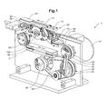
- Fig. 1 to 3 show a first embodiment of the separating device 1 in an overall view. It comprises a housing 2, not shown here in detail, on or in which the separating element 10 and the drive system are mounted. In addition, a stack receptacle 30 for articles 90 and a path transport device 60 for the separated articles 90 are present.
- the separating element 10 is arranged on a carriage 20 and rigidly connected to the carriage 20.
- the carriage 20 also includes the coupling device 100.
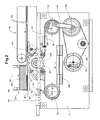
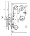
- the carriage 20 is arranged in horizontally arranged guide rails 22 within the housing 2 movable. By reciprocation of the carriage 20, the separating element 10 with a stroke A between a first and rear end position P1 (FIG. Fig. 3 ) and a second or front end position P2 ( Fig. 2 ).
- the drive system comprises on the one hand a first part 40 whose components perform a rectified movement:
- a motor 41 rotates a drive shaft 42 continuously. Their rotational movement is transmitted by means of appropriate transmission elements, here belt 44, on a disc 45.
- a converter 43 here connecting rod, transmits the movement to a second part 50 of the drive system.
- the components of the second part 50 of the drive system perform a reciprocating motion:
- a connecting rod 53 is caused by the connecting rod 43 to rotate with an alternating direction by an angle.
- the connecting rod 53 is formed as a toothed belt pulley, via which a toothed belt 51 for transmitting power inter alia to the carriage 20 and the Coupling device 100 is guided.
- the toothed belt 51 therefore also performs a reciprocating motion.
- a return element 70 and a balancing mass 80 are fixedly connected to the toothed belt 51.
- the remindzhouelemeni 70 is located on the active run of the toothed belt 51, ie on the side of the carriage 20, while the balancing mass 80 is located on the inactive Trum.
- a third part of the drive system for the separating element consists of the components which only move when the coupling is switched. This part here comprises the carriage 20 and the separating element 10 connected thereto.
- the coupling device 100 acts between the second and third parts.
- the separating element 10 comprises a slide 11, which can move approximately in the plane E of the stack support and thereby can push the lowermost object 90 in the stack 92 out of the stack 92.
- a suction element 12 is present, which is moved with the slider 11 and can suck the bottom of the articles 90.
- the connection to the vacuum source can be interrupted or made controlled.
- a conveying gap 61 of the path transport device 60 which is formed here by two or more counter-rotating conveyor belts 62.
- the movement of the carriage 20 back to the rear end position P1 is damped by a shock absorber 82.
- the carriage 20 can be held in this position by an activatable retaining element 84.
- the retaining element 84 is, for example, a permanent magnet, which is preferably displaceable automatically by a suitable drive between an active and an inactive position, ie can be switched on or switched off by means of a control signal.
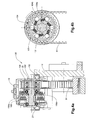
- the coupling device 100 comprises a freewheel 104 and a controllable coupling 106, for example a magnetic coupling, with coupling bush 106a and clutch disc 106b.
- Freewheel 104 and clutch 106 are arranged on a common shaft 102 which is rotatably mounted in the carriage 20.
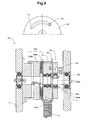
- Fig. 4a shows a section along the axis of the shaft 102.
- Fig. 4b a section through the freewheel 104 is shown perpendicular to the axis of the shaft 102.
- the inner ring 104 a of the freewheel 104 and the coupling sleeve 106 a are fixedly connected to the shaft 102.
- the clutch disc 106b is connected to the carriage 20, but freely rotatable relative to the shaft 102 in the unswitched state of the clutch 106.
- the radially outer ring 104b of the freewheel 104 carries a toothed belt pulley 105, over which the toothed belt 51 is guided.
- the movements of the components involved in the first half cycle are described below:
- the carriage is in the rear end position P1 (FIG. Fig. 3 ).
- the toothed belt 51 performs a movement about the stroke A, in the view in Fig. 1-3 and Fig. 4b clockwise (see arrow direction in Fig. 4b ).
- the freewheel 104 blocked in a clockwise motion, ie the outer ring 104b moves in the first half cycle, the inner ring 104a and thus also transmits force to the shaft 102.
- the shaft 102 rotates freely in the carriage 20 in the first half cycle.
- the carriage 20 therefore stops at P1.
- the clutch 106 is engaged, it blocks the free rotatability of the shaft 102.
- the toothed pulley 105 can not rotate freely in the carriage 20 in the first half cycle, so that the carriage 20 follows the movement of the toothed belt 51.
- the carriage 20 is therefore pulled to the right, and the separating element 10 moves from the rear end position P1 to the front end position P2. In the front end position P1, the carriage 20 abuts the return element 70.
- the toothed belt 51 carries out a stroke A in the counterclockwise direction.
- the carriage 20 In the unswitched state of the clutch 106, the carriage 20 is still at P1.
- Both inner and outer ring 104a, 104b of the freewheel 104 are decoupled.
- the outer ring 104b rolls on the inner ring 104a. Therefore, the toothed belt 51 can not transmit force to the shaft 102.
- the carriage remains in the unswitched state at P1. Since no force is transmitted to the shaft, the whole second half cycle can be used to switch the clutch.
- the carriage In the switched state of the clutch, the carriage is at the beginning of the second half cycle at the front end position P2.
- the backward movement of the toothed belt 51 is decoupled from the shaft 102 by the freewheel 104, as in the unswitched state, so that the toothed belt 51 does not retract the carriage 20 directly to the rear end position P1.
- the carriage 20 is pushed back in this case by the return element 70, which also participates in the stroke A of the toothed belt 51, in the rear end position P1.
- the clutch 106 in the backward movement is load-free, and the whole second half-cycle can be used to switch the clutch 106.
- a balancing mass 80 is attached to the inactive run of the toothed belt 51. This is constantly moved with the timing belt 51 back and forth.
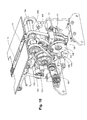
- Fig. 5-9 show the second embodiment of the invention, in which the coupling device 100 is spatially separated from the separating element 10.
- the separating element 10 is in turn arranged on a carriage 20 and movable in a guide.
- the basic structure of the drive system is similar to in the first embodiment.
- the continuous rectified movement of a drive shaft 42 is converted by means of a connecting rod 43 in a reciprocating motion of a connecting rod 53.
- a toothed belt 51 is used to transmit power to the carriage 20. It is fixedly connected to the carriage 20 in this embodiment.
- the timing belt is guided over deflections.
- the coupling device 100 is integrated in one of the deflections. It is therefore stationary and is not moved with the carriage 20.
- the drive system comprises, as in the first embodiment, a first part whose components perform a rectilinear motion, a second part whose components perform a continuous reciprocating motion, and a third part whose components are reciprocated only with the clutch engaged. Between the second and third part, the coupling device acts.
- the first part comprises motor (not shown here), drive shaft 42 and a disc 45 on which the connecting rod 43 is mounted.
- the second part here comprises only the connecting rod 53 and the return element 70 disposed thereon, which is designed here as a driving cam.
- the third part of the drive system comprises, among other things, the carriage 20 and the toothed belt 51.
- the connecting rod 53 is arranged on a shaft 102 which is rotatably mounted in the housing 2.
- a freewheel 104 is integrated, the inner part 104a is fixedly connected to the shaft 102.
- the connecting rod 43 is fastened.
- Coaxial with the freewheel 104 is a toothed belt pulley 105 and a clutch 106 with the coupling sleeve 106a and clutch disc 106b.
- the coupling socket 106a is fixedly connected to the shaft 102.
- the toothed belt pulley 105 is on the shaft 102 in itself freely rotatable. By the coupling 106, the free rotation of the pulley 105 can be blocked.
- the return element 70 is firmly connected to the connecting rod 53.
- the toothed belt pulley 105 has a suitably designed counter element 72, which can cooperate with the return element 70.
- the counter element 72 is in the case of Fig. 8 and 9 a side wall of a groove and in the case of Fig. 7 an axially projecting pin.
- the movements of the components involved in the first half cycle are described below:
- the carriage is in the rear end position P1 (FIG. Fig. 8 ).
- the connecting rod 53 is rotated by the drive by a certain angle in a clockwise direction.
- the freewheel 104 which as in Fig. 4b is constructed, blocked when moving in a clockwise direction, so that the shaft 102 is also rotated.
- the clutch 106 is not active, the pulley 105 stops.
- the toothed belt 51 is therefore not moved, and the separating element 10 remains at P1.
- the pulley 105 rotates with the shaft 102 and moves the toothed belt 51 by the stroke A.
- the active run of the toothed belt 51 is thus moved by the amount A to the right. Since the separating element 10 is fixedly coupled to the toothed belt 51, this is also moved to the right and reaches the front end position P2.
- the freewheel 104 decouples the connecting rod 53 from the shaft 102. If the clutch 106 was not previously switched, the separating element 10 remains at P1. If the clutch 106 was previously switched, the toothed belt pulley 105 by the driving cam 70, which is connected to a counter-element 72 at the Timing belt pulley 105 cooperates, turned back to its original position. With it, the toothed belt 51 rotates and moves the separating element 10 from the front end position P2 back to the rear end position P1.
- a balancing mass 80 is attached to the inactive run of the toothed belt 51.
- Shock absorbers 82 and / or retaining elements 84 may be present as in the first embodiment.
- the masses of those components that are continuously reciprocated are reduced. In principle, it is only the connecting rod, which performs a reciprocating motion.
- the moving masses are largely distributed symmetrically, because the balancing mass is only moved when the carriage is moved. This has advantages because the imbalance is reduced.
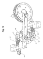
- a third embodiment is in Fig. 10-13 shown.
- Fig. 10 and 11 show the third embodiment of two different sides.
- the basic structure of the drive system is similar to the second embodiment.
- the separating element 10 is fixedly connected to the toothed belt 51.
- the toothed belt 51 is analogous to the second embodiment via the clutch 106 and the (not visible) freewheel connected to the connecting rod 53.
- the connecting rod 53 is fixedly connected to two return elements 70, which can interact with two counter-elements 72.
- the connecting rod 53 is connected via the connecting rod 43 to the drive pulley 45.
- the toothed belt 51 of the third embodiment is driven, controlled and moved analogously to the toothed belt 51 of the second embodiment.
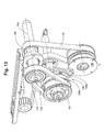
- the third embodiment has an in Fig. 12 and 13 illustrated energy storage mechanism.
- a first part of the energy storage mechanism is in Fig. 12 and includes spring assemblies 120 which receive, store and release kinetic energy.
- the kinetic energy is converted into potential energy as it is absorbed, stored as potential energy, and converted back to kinetic energy upon release.
- the kinetic energy is released at least partially as thermal energy to the environment, ie that dissipation takes place.
- Dissipation of at least parts of the kinetic energy to be absorbed per cycle can be slow, for example, over several seconds or minutes. In particular, dissipation can help to minimize or prevent vibrations of the mechanical parts.
- a second part of the energy storage mechanism which comprises a second clutch 130, a pulley 131 and a gear 133 with freewheel.
- the second part of the energy storage mechanism may allow or prevent changes in the expansion of the spring assemblies 120 through the second clutch 130.
- the spring packs 120 can store them as potential energy after absorption of kinetic energy and, if required, can switch off again as kinetic energy.
- the second part of the energy storage mechanism also serves as a retaining element, which selectively locks the separating element 10 in the rear end position P1.
- the counter-elements 72 are formed such that they at least temporarily non-positively with first ends of Spring packs 120 are in contact.
- the spring assemblies 120 are non-positively connected at their second ends to the housing 2.
- the spring packs 120 are secured to the housing and can be biased by pretensioners 121 relative to the housing 2 variably with a desired force. If the counter elements 72 are in a rear end position, in which the separating element 10 connected to them via the toothed belt 51 must be in its rear end position P1, then the counter elements 72 compress the spring packs 120 together.
- the counter elements 72 During a movement towards this rear end position (ie in the second half cycle), the counter elements 72 increasingly compress the spring assemblies 120, as a result of which the spring assemblies 120 increasingly counteract this movement.
- the force of the spring assemblies 120 acts on the counter-elements 72 and supports the movement away from the rear end position.
- kinetic energy of the counter elements 72 is converted in the second half cycle in the rear end position into potential energy and stored and converted back into kinetic energy in the subsequent first half cycle and delivered to the counter elements 72.
- the counter-elements 72 and thereby also the spring assemblies 120 can be selectively fixed in position or moved freely. In this way, the energy absorbed by the spring packs 120 can be absorbed, stored and also released again.
- the second part of the energy storage mechanism comprises the second clutch 130.
- the second clutch 130 comprises a coupling bush 130a which is fixedly connected to the housing 2.
- a clutch plate 130b of the second clutch 130 is fixedly connected to a pulley 131 which is connected to a toothed belt 132.
- the toothed belt 132 is connected to a gear 133 with freewheel.
- the gear 133 with freewheel is connected to a deflection shaft 134.
- the deflection shaft 134 is fixedly connected to a Umlenk leopardrad 135, which deflects the toothed belt 51.
- the freewheel of the gear 133 is formed such that an optionally present rotation of the deflection shaft 134 in the second half cycle runs freely relative to the gear 133.
- gear 133 and guide shaft 134 firmly engage each other, so that a fixed in position gear 133 prevents the guide shaft 134 from rotating and thereby fixed.
- Both clutches 106, 130 if switched, are only switched during the second half-cycle. Due to the two corresponding freewheels, no forces are applied to the two clutches 106, 130 in the second half cycle. If the two corresponding freewheels firmly grip again in the subsequent first half-cycle, the switching states of the two clutches 106, 130 decide whether the separating element 10 is moved or not.
- the separating element 10 In the first half-cycle, the separating element 10 is moved from the rear end position P1 to the front end position P2 when the clutch 106 is activated (ie engaged) and the second clutch 130 is deactivated (ie disengaged). With correspondingly timed deactivation of the second clutch 130, the spring assemblies 120 in the first half cycle from the beginning of the movement of the separating element 10, the stored energy to the return elements 70 and thus to the separating element 10 in its direction of movement and thereby support the movement of the separating element 10.
- the clutch 106 is not activated and the second clutch 130 is activated, then the separating element 10 does not move and remains in the rear end position P1.
- the kinetic energy absorbed by the spring assemblies 120 remains stored in the form of potential energy.
- the connecting rod 53 moves by return elements 70, the counter elements 72, if the separating element 10 has been moved in the previous first half cycle in the front end position P2.
- the separating element 10 is moved from the front end position P2 to the rear end position P 1.
- the counter-elements 72 come into frictional contact with the spring packs 120 and increasingly press them together until the end of the second half-cycle. If the separating element 10 was not moved into the front end position P2 in the preceding first half cycle, then the separating element 10 is still in the rear end position P1 and only the connecting rod 53 and the return elements 70 are moved, but not the counter elements 72.
- the bearing surface for the stack can also be coupled to the separating element and moved back and forth. The moving masses are then larger, but the objects are well supported at all times.
Landscapes
- Engineering & Computer Science (AREA)
- Mechanical Engineering (AREA)
- Transmission Devices (AREA)
Abstract
Description
- Die Erfindung liegt auf dem Gebiet des Maschinen- und Anlagenbaus sowie der Förder- und Verarbeitungstechnik. Sie betrifft eine Vorrichtung und ein Verfahren zum Erzeugen einer gesteuerten Hin- und Herbewegung eines beweglichen mechanischen Elements. Die Erfindung ist insbesondere bei einer Vereinzelungsvorrichtung zum gesteuerten Separieren von Gegenständen aus einem Stapel von Gegenständen einsetzbar. Die Gegenstände sind beispielsweise Druckereiprodukte, die aus einem Stapel von Druckereiprodukten herausgeschoben werden.
- Aus der
DE-A 33 20491 ist ein Schiebeanleger für tafelförmiges Material bekannt. Der jeweils untere Gegenstand eines Gegenstandsstapels wird durch ein Separierelement aus dem Stapel herausgeschoben, so dass er von Förderbändern einer Wegtransportvorrichtung ergriffen und abtransportiert werden kann. Das Separierelement ist linear verschiebbar gelagert und über ein Pleuelstangensystem mit einer Antriebswelle gekoppelt. Die kontinuierliche Drehbewegung der Antriebswelle wird somit in eine lineare Hin- und Herbewegung des mechanischen Elements zwischen zwei Endlagen umgesetzt. Bei der bekannten Anlage wird pro Umdrehung der Antriebswelle ein Gegenstand aus dem Stapel herausgeschoben. Möchte man die Abgabe von Gegenständen unterbrechen, muss der Antrieb gestoppt werden. - Insbesondere in der Druckereitechnik, aber auch in anderen Anwendungsgebieten, ist es notwendig, einzelne Gegenstände auf Anforderung hin sowie taktgenau zur Verfiigung zu stellen. Im Bereich der Produktion von Zeitungen und Zeitschriften wird zunehmend verlangt, dass die Hauptprodukte, z.B. die eigentliche Zeitung bzw. Zeitschrift, individuell mit einer oder mehreren Beilagen versehen werden können. Die Beilagen sind z.B. Werbebroschüren, Flyer, Warenproben, CDs und dergleichen. Sie können eine Dicke von 3 mm und mehr aufweisen und steif sein, so dass bekannte Vereinzelungsvorrichtungen, die den Gegenstand beim Separieren biegen, nicht eingesetzt werden können. Die Gegenstände werden als Stapel zur Verfügung gestellt. Es ist daher notwendig, diese Gegenstände gezielt und taktgenau aus dem Stapel zu separieren. Dabei soll der hohe Verarbeitungstakt von zur Zeit bis zu 30'000 Produkten pro Stunde beibehalten werden. Ein An- und Abschalten des Antriebsmotors der Vereinzelungsvorrichtung bzw. des Separierelements kommt bei diesen Taktzahlen nicht in Frage.
- Es ist daher ebenfalls bekannt, das Separierelement mittels einer steuerbaren Kupplung an einen kontinuierlich betriebenen Antrieb zu koppeln, um auf Anforderung hin einen Gegenstand zu separieren. Hierbei wird mittels eines Umsetzers, z.B. einer exzentrisch gelagerten Pleuelstange, die Drehbewegung der Antriebswelle in eine Hin- und Herbewegung eines Antriebselements, z.B. einer Pleuelscheibe, umgesetzt. Über die Kupplung kann das Separierelement mit dem Antriebselement gekoppelt werden, so dass es im gekoppelten Zustand mitgenommen wird und ebenfalls eine Hin- und Herbewegung vollzieht. Um schnellen Verschleiss zu vermeiden, muss die Kupplung im lastfreien Zustand geschaltet werden. Der lastfreie Zustand liegt nur in den Umkehrpunkten bzw. Umkehrpositionen der Hin- und Herbewegung des Antriebselements vor. Das ideale Zeitfenster zum Schalten ist daher sehr klein, so dass die Kupplung entweder unter Last geschaltet oder die Taktzahl beschränkt werden muss.
- Der Erfindung liegt daher die Aufgabe zugrunde, eine Vereinzelungsvorrichtung an sich bekannter Art derart weiterzuentwickeln, dass auch bei hohen Taktzahlen ein verschleissarmer Betrieb der Kupplung gewährleistet ist. Allgemein soll ein Antriebssystem für ein mechanisches Element zur Verfügung gestellt werden, mit welchem dieses gezielt zu einer Hin- und Herbewegung in einem extern vorgegebenen Takt veranlasst werden kann.
- Die Aufgabe wird gelöst durch eine Vorrichtung mit den Merkmalen von Anspruch 1 sowie ein Verfahren mit den Merkmalen von Anspruch 11. Vorteilhafte Weiterbildungen der Erfindung ergeben sich aus den abhängigen Ansprüchen, der Beschreibung und den Zeichnungen.
- Die erfindungsgemässe Vorrichtung dient zum Erzeugen einer gesteuerten Hin- und Herbewegung eines beweglichen mechanischen Elements zwischen einer ersten Endlage und einer zweiten Endlage in einem extern vorgegebenen Takt. Sie umfasst wenigstens ein kontinuierlich zwischen zwei Umkehrpositionen hin- und herbewegtes Antriebselement. Das Antriebselement ist beispielsweise mit der Antriebswelle eines Motors so gekoppelt, dass aus der kontinuierlich gleichgerichteten Bewegung der Antriebswelle eine Bewegung mit wechselnder Richtung zwischen zwei Endlagen/Umkehrpositionen gemacht wird. Ausserdem ist eine Kopplungsvorrichtung mit einer steuerbaren Kupplung zum selektiven Ankoppeln des mechanischen Elements an das Antriebselement vorhanden. Im aktiven (geschalteten) Zustand der Kupplung wird das mechanische Element bewegt, im nicht aktiven Zustand der Kupplung soll es stehenbleiben.
- Erfindungsgemäss umfasst die Kopplungsvorrichtung zusätzlich einen Freilauf und ist derart eingerichtet, dass das mechanische Element im aktiven Zustand der Kupplung während eines ersten Halbzyklus der Bewegung des wenigstens einen Antriebselements mit dem Antriebselement gekoppelt ist und von der ersten Endlage in die zweite Endlage bewegt wird. Während eines zweiten Halbzyklus der Bewegung des Antriebselements ist das mechanische Element durch Wirken des Freilaufs vom Antriebselement im Wesentlichen unbeeinflusst. Um das mechanische Element im aktiven Zustand der Kupplung wieder in die Ausgangslage zurückzubringen, ist ein Rückführungselement vorhanden. Dieses wird synchron mit dem wenigstens einen Antriebselement bewegt. Es kann wenigstens indirekt auf das mechanische Element einwirken derart, dass das mechanische Element während des zweiten Halbzyklus von der zweiten Endlage zurück in die erste Endlage bewegt wird.
- Im Folgenden wird der Einfachheit halber die Bewegung des mechanischen Elements zwischen der ersten Endlage und der zweiten Endlage und die entsprechende Bewegung des Antriebelements als Vorwärtsbewegung bezeichnet und die Bewegung in die andere Richtung als Rückwärtsbewegung.
- Durch den Freilauf wird realisiert, dass im geschalteten Zustand der Kupplung nur die Vorwärtsbewegung des wenigstens einen Antriebselements auf das mechanische Element übertragen wird und die Kupplung dabei unter Last steht. Die Rückwärtsbewegung des Antriebselements wird vom mechanischen Element abgekoppelt, so dass die Kupplung bei der Rückwärtsbewegung lastfrei ist. Die Kopplungsvorrichtung überträgt also selektiv nur die Vorwärtsbewegung des Antriebselements auf das mechanische Element und dies auch nur, wenn die Kupplung aktiv ist. Die Kupplung ist daher im zweiten Halbzyklus lastfrei und kann somit lastfrei geschaltet (aktiviert bzw. deaktiviert) werden. Das Rückführungselement ist grundsätzlich nicht über die steuerbare Kupplung mit dem Antriebselement gekoppelt, sondern auf andere Weise, z.B. indem es am Antriebselement befestigt bzw. mit diesem fest verbunden ist. Mit verbunden ist hier und an allen anderen Stellen der Anmeldung gemeint, dass die Bewegungen von verbundenen Teilen mindestens zeitweise gekoppelt sind. Das Rückfiihrungselement überträgt die Rückwärtsbewegung des Antriebselements auf das mechanische Element. Damit wird dieses unabhängig vom Zustand der Kupplung während des zweiten Halbzyklus von der zweiten Endlage in die erste Endlage verfahren, falls es die erste Endlage im ersten Halbzyklus verlassen hat.
- Durch die Erfindung gelingt es, die Zeit, die zum lastfreien Schalten der Kupplung zur Verfügung steht, gegenüber dem herkömmlichen Fall signifikant zu verlängern, nämlich auf die Hälfte der Taktdauer bzw. den ganzen zweiten Halbzyklus gegenüber einem Bruchteil der Taktdauer beim Schalten in den Umkehrpunkten. Somit werden kürzere Taktdauern bzw. grössere Taktzahlen als bei herkömmlichen Anlagen möglich.
- Die Hin- und Herbewegung des Antriebselements kann eine Rotation um einen kleinen Winkel sein oder auch eine lineare Bewegung. Auch Bewegungen entlang beliebigen Bahnkurven zwischen zwei Endlagen können durch geeignete mechanische Umsetzung bzw. Führung des Antriebselements oder des mechanisches Elements realisiert werden. Als Antriebselement dient beispielsweise eine Pleuelscheibe, die über eine Pleuelstange exzentrisch mit der Antriebswelle verbunden ist. Die Hin- und Her-Rotation der Pleuelscheibe kann über Mittel zur Kraftübertragung, z.B. einen Zahnriemen, auf weitere Komponenten übertragen werden; Zahnriemen und weitere Komponenten sind daher ebenfalls Antriebselemente im Sinne der Erfindung, wenn sie mit wechselnder Richtung zwischen zwei Endlagen bewegt werden. Das mechanische Element wird selektiv an eine der Komponenten, die sich hin und her bewegen, angekoppelt.
- Die Kopplungsvorrichtung kann auf verschiedene Arten mechanisch realisiert werden. Die Kopplungsvorrichtung kann beispielsweise zusammen mit dem Separierelement an einem verfahrbaren Schlitten angeordnet sein. Die Kopplungsvorrichtung kann auch räumlich vom mechanischen Element getrennt sein, beispielsweise in eine Umlenkung für einen Zahnriemen, der zur Kraftübertragung verwendet wird, integriert sein. In beiden Fällen dient der Freilauf dazu, die Kraftübertragung vom Antriebselement auf das mechanische Element während der Rückwärtsbewegung des Antriebselements zu unterbinden. Während der Vorwärtsbewegung wird die Antriebskraft nur im aktiven Zustand der Kupplung übertragen. Im inaktiven Zustand der Kupplung wird auf das mechanische Element auch keine Kraft ausgeübt. Es wird also nicht in Bewegung gesetzt oder auf andere Art aktiviert.
- Die Kopplungsvorrichtung umfasst vorzugsweise eine Welle, die drehbar angeordnet ist. Der Freilauf befindet sich zwischen der Welle und dem Antriebselement, so dass eine Antriebskraft nur in einer Richtung bzw. nur im ersten Halbzyklus auf die Welle übertragen wird. Die steuerbare Kupplung befindet sich zwischen dem Separierelement und der Welle und koppelt das mechanische Element selektiv an die Welle an, so dass die Welle die Antriebskraft auf das mechanische Element übertragen kann. Die Kopplung ist direkt oder indirekt über Kraftübertragungsmittel. In der Gegenrichtung wird keine Kraft auf die Welle übertragen. Diese bleibt in ihrer Drehlage am Ende des ersten Halbzyklus stehen. Das mechanische Element wird gegebenenfalls durch das Rückfuhrungselement zurück in die Ausgangsposition gebracht. Die Welle wird auch beim Zurückführen nicht gedreht. Somit wirkt beim Zurückführen keine Kraft auf die Kupplung.
- Zur Kraftübertragung werden vorzugsweise Zahnriemen eingesetzt. Es sind jedoch auch andere Übertragungsmechanismen möglich, beispielsweise im Reibschluss oder mit starren Kopplungselementen, z.B. gekoppelten Hebeln.
- Das Rückführungselement ist beispielsweise ein Schieber, der das mechanische Element durch Stossen bewegt. Es kann das mechanische Element aber auch in die Ausgangsposition zurückziehen.
- In einer ersten bevorzugten Ausführungsform ist die Kopplungsvorrichtung zusammen mit dem mechanischen Element beweglich, insbesondere in einen gemeinsamen Schlitten integriert. Die Kraftübertragung erfolgt über einen Zahnriemen, der über eine Zahnriemenscheibe geführt ist. Die Zahnriemenscheibe ist wiederum mit einem äusseren Ring des Freilaufs fest verbunden. Ein innerer Ring des Freilaufs ist mit der Welle starr gekoppelt. Die Welle ist im Schlitten drehbar gelagert. Durch die Kupplung kann die freie Drehbarkeit der Welle gegenüber dem Schlitten blockiert werden.
- Für dieses Beispiel werden im Folgenden die Bewegungen der beteiligten Komponenten im ersten Halbzyklus beschrieben: Das mechanische Element und der Schlitten befinden sich in der ersten Endlage. Im ersten Halbzyklus wird das Antriebselement, hier der Zahnriemen, in Vorwärtsrichtung bewegt. Mit dem Antriebselement bewegt sich auch das Rückführungselement. Der Freilauf blockiert bei dieser Bewegung des Zahnriemens, d.h. der äussere Ring nimmt den inneren Ring mit und überträgt somit auch Kraft auf die Welle. Wenn die Kupplung nicht geschaltet ist, dreht die Welle frei im Schlitten. Der Schlitten bleibt daher stehen. Wenn die Kupplung geschaltet ist, blockiert sie die freie Drehbarkeit der Welle. Die Zahnriemenscheibe kann sich somit nicht mehr frei im Schlitten drehen, so dass der Schlitten der Bewegung des Zahnriemens folgt, in Vorwärtsrichtung bewegt wird und die zweite Endlage erreicht.
- Im zweiten Halbzyklus bewegt sich der Zahnriemen in Rückwärtsrichtung. Im ungeschalteten Zustand der Kupplung befindet sich der Schlitten noch immer in der ersten Endlage. Bei einer Bewegung in Rückwärtsrichtung sind innerer und äusserer Ring des Freilaufs entkoppelt. Der Zahnriemen kann daher während des ganzen zweiten Halbzyklus keine Kraft auf die Welle übertragen. Im ungeschalteten Zustand der Kupplung befindet sich der Schlitten zu Beginn des zweiten Halbzyklus an der ersten Endlage. Dort bleibt er während des ganzen zweiten Halbzyklus stehen. Im geschalteten Zustand der Kupplung befindet sich der Schlitten zu Beginn des zweiten Halbzyklus an der zweiten Endlage. Die Rückwärtsbewegung des Zahnriemens wird unabhängig vom Zustand der Kupplung durch den Freilauf von der Welle abgekoppelt, so dass der Zahnriemen den Schlitten nicht direkt zur ersten Endlage zurückzieht. Der Schlitten wird in diesem Fall durch das Rückführungselement in die erste Endlage zurückgeschoben. Unabhängig vom Zustand der Kupplung ist die Kupplung daher bei der Rückwärtsbewegung lastfrei. Der ganze zweite Halbzyklus kann zum lastfreien Schalten der Kupplung genutzt werden. Die Steuereinrichtung der Anlage übermittelt der Kupplung Schaltsignale, die während des zweiten Halbzyklus wirksam werden.
- In einer zweiten bevorzugten Ausführungsform ist die Kopplungsvorrichtung ortsfest, insbesondere in Gehäuse integriert, in dem auch das mechanische Element gelagert ist. Die Kraftübertragung erfolgt ebenfalls über einen Zahnriemen, der mit dem mechanischen Element fest verbunden und über eine Zahnriemenscheibe geführt ist. Die Zahnriemenscheibe ist auf einer Welle drehbar gelagert. Die Welle ist im Gehäuse drehbar gelagert. Durch die Kupplung kann die freie Drehbarkeit der Zahnriemenscheibe relativ zur Welle blockiert werden. Als Antriebselement dient hier eine Pleuelscheibe, die in Hin- und Herbewegung versetzt wird. Sie ist über den Freilauf ebenfalls auf der Welle angeordnet. Der innere Ring des Freilaufs ist mit der Welle verbunden, und der äussere Ring des Freilaufs ist mit der Pleuelscheibe verbunden.
- Für dieses Beispiel werden im Folgenden die Bewegungen der beteiligten Komponenten im ersten Halbzyklus beschrieben: Das mechanische Element und der Zahnriemen befinden sich in der ersten Endlage. Das Antriebselement - hier die Pleuelscheibe - wird in Vorwärtsrichtung gedreht. In dieser Richtung blockiert der Freilauf, d.h. es nimmt bei seiner Bewegung die Welle mit. Wenn die Kupplung nicht aktiv ist, kann sich die Welle relativ zur Zahnriemenscheibe drehen, im aktiven Zustand der Kupplung ist diese Drehung blockiert. Die Zahnriemenscheibe wird daher durch das Antriebselement nur mitbewegt, wenn die Kupplung geschaltet ist, so dass das mechanische Element in die zweite Endlage bewegt wird. Bei inaktiver Kupplung bleiben der Zahnriemen und damit auch das mechanische Element an der ersten Endlage stehen. Im zweiten Halbzyklus entkoppelt der Freilauf die Pleuelscheibe von der Welle, so dass die Welle von der Rückwärtsbewegung der Pleuelscheibe unbeeinflusst bleibt. Durch ein Rückführungselement wird die Welle jedoch wieder zurück in die Ausgangslage gedreht, wenn es diese zuvor verlassen hat. Auch bei dieser Ausführungsform ist die Kupplung daher unabhängig von ihrem Zustand bei der Rückwärtsbewegung lastfrei. Der ganze zweite Halbzyklus kann zum lastfreien Schalten der Kupplung genutzt werden. Die Steuereinrichtung der Anlage übermittelt der Kupplung Schaltsignale, die während des zweiten Halbzyklus wirksam werden.
- Zur Vermeidung von Unwucht beim Betätigen des mechanischen Elements ist vorzugsweise eine Ausgleichsmasse vorhanden, die wenigstens dann mitbewegt wird, wenn auch das mechanische Element bewegt wird. Bei einer Kraftübertragung mittels Zahnriemen ist sie vorzugsweise am inaktiven Trum des Zahnriemens angebracht. Lösungen, bei denen der Zahnriemen nicht ständig mitbewegt wird, wie z.B. das oben beschriebene zweite Ausführungsbeispiel, haben bei einem solchen Aufbau Vorteile, da ansonsten die Ausgleichsmasse auch bei stillstehendem mechanischen Element hin und her schwingt.
- Die Kupplung, beispielsweise eine steuerbare Magnetkupplung, empfängt Steuersignale von einer Steuereinrichtung. Das Zeitfenster, innerhalb dessen die Steuersignale die Kupplung erreichen müssen, wird durch die Erfindung deutlich vergrössert. Die Steuereinrichtung ist so eingerichtet, dass ihre Steuersignale von der Kupplung im zweiten Halbzyklus empfangen werden.
- Um die Rückwärtsbewegung des mechanischen Elements zu stoppen bzw. Schläge abzudämpfen, ist vorzugsweise ein Stossdämpfer vorhanden, der in der ersten Endlage auf das mechanische Element bzw. eine damit starr verbundene Komponente, wie z.B. einen Schlitten, wirkt. Es kann aber auch ein Energiespeichermechanismus vorgesehen sein, welcher Energie der bewegten Teile und insbesondere des mechanischen Elements aufnehmen und wieder an dieselben Teile direkt oder indirekt abgeben kann. Insbesondere muss der Energiespeichermechanismus die Energie nicht unmittelbar nach dem Aufnehmen wieder abgeben, sondern kann diese für eine bestimmte Zeit speichern.
- Optional kann der Energiespeichermechanismus unterschiedliche Energieformen aufnehmen, abgeben und insbesondere speichern.
- Als weitere Option kann der Energiespeichermechanismus Energieformen mindestens einmal umwandeln, insbesondere zweimal. Beispielsweise wird beim Aufnehmen der Energie in den Energiespeichermechanismus eine erste Energieform in eine zweite Energieform umgewandelt, in der zweiten Energieform gespeichert und beim Abgeben wieder in die erste Energieform umgewandelt.
- Insbesondere handelt es sich bei der ersten Energieform um kinetische Energie und bei der zweiten Energieform um potentielle Energie. Die kinetische Energie der bewegten Teile kann beispielsweise auch zuerst in eine andere Energieform umgewandelt und erst danach dem Energiespeichermechanismus zugeführt werden und umgekehrt. Verschiedene Energieformen sind beispielsweise kinetische, potentielle, chemische, thermische und elektrische Energie.
- Der Energiespeichermechanismus kann beispielsweise Federn und/oder Federpakete umfassen, insbesondere Spiralfedern, Schraubenfedern, Spiraldruckfedern, Torsionsfedern, Blattfedern, Gasdruckfedern und/oder andere Biege-, Zug- und Gasfedern. Der Energiespeichermechanismus kann beispielsweise auch Kreisel, Schwungräder und/oder andere Drehmassenspeicher umfassen. Der Energiespeichermechanismus kann aber beispielsweise auch Batterien, Akkumulatoren, Kondensatoren und/oder andere Speicher für elektrische Energie umfassen, insbesondere in Verbindung mit mindestens einem elektromechanischen Wandler. Der Energiespeichermechanismus kann die Energie der Rückwärts- und/oder Vorwärtsbewegung des mechanischen Elements aufnehmen und wieder abgeben. Das Aufnehmen, Abgeben und insbesondere Speichern der Energie im Energiespeichermechanismus erfolgt insbesondere dann, wenn das mechanische Element sich nahe und/oder an mindestens einer der Endlagen befindet. Mit nahe einer Endlage befinden ist gemeint, dass sich das mechanische Element in einem Wirkungsbereich gegebener Länge um die Endlage befindet.
- Soll das mechanische Element für eine gewisse Zeit nicht aktiviert werden, kann vorzugsweise ein Rückhalteelement zugeschaltet werden. Das Rückhalteelement übt in der ersten Endlage eine Kraft auf das mechanische Element aus, die der Antriebskraft entgegenwirkt. Es hält das mechanische Element dadurch in der ersten Endlage zurück und verhindert, dass es allein aufgrund der Vibrationen der Gesamtanlage die Endlage verlässt. Das Rückhalteelement ist beispielsweise durch einen Elektromagneten oder durch einen beweglichen Dauermagneten realisiert, der wahlweise zugeschaltet werden kann. Das Rückhalteelement kann beispielsweise auch eine weitere schaltbare Kupplung umfassen. Auch etwa ein Energiespeichermechanismus kann mindestens teilweise eine Funktion des Rückhalteelements erfüllen.
- Das erfindungsgemässe Antriebssystem, also selektives Ankoppeln an die Hinbewegung eines hin- und herbewegten Antriebselements mittels einer Kupplung, grundsätzliches Abkoppeln von der Rückwärtsbewegung mittels eines Freilaufs sowie Zurückschieben mittels eines mit dem Antriebselement mitbewegten Schiebers, lässt sich bei allen Vorgängen verwenden, in denen Bewegungen eines mechanischen Elements schnell und im vorgegebenen Takt ausgelöst werden müssen. Das mechanische Element kann Teil einer übergeordneten Anlage sein. Das erfindungsgemässe Antriebssystem kann zusätzlich noch Komponenten umfassen, die eine gleichgerichtete Bewegung ausführen, z.B. eine Antriebswelle und/oder einen Motor, wobei das Antriebselement durch geeignete Kopplung mit diesen Komponenten eine kontinuierliche Hin- und Herbewegung im gewünschten Takt ausführt. Die Kopplungsvorrichtung mit der steuerbaren Kupplung und dem Freilauf wirkt zwischen dem nur auf Anforderung zu bewegenden mechanischen Element und dem wenigstens einen kontinuierlich hin- und herbewegten Antriebselement.
- Die Antriebsvorrichtung wird bevorzugt für den Antrieb eines Separierelements einer Vereinzelungsvorrichtung für Gegenstände eingesetzt. Das Separierelement ist zwischen der ersten Endlage und einer zweiten Endlage verfahrbar und kann dabei auf einen Gegenstand eines Stapels einwirken, um diesen vom Stapel zu separieren. Das Separierelement ist beispielsweise ein Schieber und/oder ein Sauger und/oder wirkt mittels Reibung.
- Um das Handling zu vereinfachen und/oder um Produkteströme zusammenzuführen, können auch zwei oder mehr Vereinzelungsvorrichtungen parallel vorgesehen werden, die auf Anforderung alternierend Gegenstände vereinzeln (Splittbetrieb). Dies ist beispielsweise von Vorteil, wenn Gegenstände von einem Stapel vereinzelt werden sollen, die so dick sind, dass der Stapelschacht bei einem normalen 1:1-Betrieb schnell entleert würde.
- Beispiele der Erfindung sind in den Zeichnungen dargestellt und nachfolgend beschrieben. Es zeigen:
- Fig. 1
- eine dreidimensionale Ansicht einer ersten Ausführungsform einer Vereinzelungsvorrichtung, bei der die Kopplungsvorrichtung in einen Schlitten für das Separierelement integriert ist;
- Fig. 2
- die Vereinzelungsvorrichtung aus
Fig. 1 in Seitenansicht, wobei sich das Separierelement in einer zweiten bzw. vorderen Endlage befindet; - Fig. 3
- die Vereinzelungsvorrichtung aus
Fig. 1 in Seitenansicht, wobei sich das Separierelement in einer ersten bzw. hinteren Endlage befindet; - Fig. 4a+b
- Schnittansichten der in
Fig. 1-3 verwendeten Kopplungsvorrichtung; - Fig. 5
- eine dreidimensionale Ansicht einer zweiten Ausführungsform einer Vereinzelungsvorrichtung, bei der die Kopplungsvorrichtung in eine Umlenkung für einen Zahnriemen integriert ist;
- Fig. 6
- die Vereinzelungsvorrichtung aus
Fig. 5 in Seitenansicht; - Fig. 7
- eine dreidimensionale Ansicht der in
Fig. 5 und6 verwendeten Kopplungsvorrichtung; - Fig. 8
- eine Seitenansicht des Antriebssystems der Vereinzelungsvorrichtung aus
Fig. 5 ; - Fig. 9
- eine Schnittansichten der in
Fig. 5-8 verwendeten Kopplungsvornchtung; - Fig. 10
- eine dreidimensionale Ansicht einer dritten Ausführungsform einer Vereinzelungsvorrichtung, bei der ein Energiespeichermechanismus integriert ist;
- Fig. 11
- eine dreidimensionale Ansicht der Vereinzelungsvorrichtung aus
Fig. 10 von einer anderen Seite; - Fig. 12
- eine dreidimensionale Ansicht eines ersten Teils des in
Fig. 10 und11 verwendeten Energiespeichermechanismus (von derselben Seite betrachtet wie inFig. 11 ); - Fig. 13
- eine dreidimensionale Ansicht eines zweiten Teils des in
Fig. 10 und11 verwendeten Energiespeichermechanismus (von derselben Seite betrachtet wie inFig. 12 ). - Die Figuren zeigen einen Schiebeanleger, also eine Vereinzelungsvorrichtung, in die das erfindungsgemässe Antriebssystem integriert ist und zum Antrieb eines Separierelements genutzt wird. Das Separierelement ist ein kombiniertes Schiebe-und Saugelement, mit welchem flache Gegenstände, z.B. Druckereiprodukte, von unten aus einem Stapel hinausgeschoben werden. Das im Folgenden beschriebene Antriebs- und Kopplungsprinzip für das Separierelement ist jedoch nicht auf diesen Anwendungsfall beschränkt, sondern grundsätzlich bei allen schnell auszulösenden Bewegungen, die in einem vorgegebenen Takt erfolgen müssen, einsetzbar.
-
Fig. 1 bis 3 zeigen eine erste Ausführungsform der Vereinzelungsvorrichtung 1 in Gesamtansicht. Sie umfasst ein hier nicht detailliert dargestelltes Gehäuse 2, an bzw. in dem das Separierelement 10 sowie das Antriebssystem gelagert sind. Ausserdem sind eine Stapelaufnahme 30 für Gegenstände 90 sowie eine Wegtransportvorrichtung 60 für die separierten Gegenstände 90 vorhanden. Das Separierelement 10 ist auf einem Schlitten 20 angeordnet und mit dem Schlitten 20 starr verbunden. Der Schlitten 20 umfasst ausserdem die Kopplungsvorrichtung 100. Der Schlitten 20 ist in horizontal angeordneten Führungsschienen 22 innerhalb des Gehäuses 2 beweglich angeordnet. Durch Hin- und Herbewegung des Schlittens 20 wird das Separierelement 10 mit einem Hub A zwischen einer ersten bzw. hinteren Endlage P1 (Fig. 3 ) und einer zweiten bzw. vorderen Endlage P2 (Fig. 2 ) verfahren. - Das Antriebssystem umfasst einerseits einen ersten Teil 40, dessen Komponenten eine gleichgerichtete Bewegung durchführen: Ein Motor 41 dreht eine Antriebswelle 42 kontinuierlich. Ihre Drehbewegung wird mittels entsprechender Übertragungselemente, hier Riemen 44, auf eine Scheibe 45 übertragen. Ein Umsetzer 43, hier Pleuelstange, überträgt die Bewegung auf einen zweiten Teil 50 des Antriebssystems. Die Komponenten des zweiten Teils 50 des Antriebssystems führen eine Hin- und Herbewegung durch: Eine Pleuelscheibe 53 wird durch die Pleuelstange 43 zu einer Drehbewegung mit wechselnder Richtung um einen Winkel veranlasst. Die Pleuelscheibe 53 ist als Zahnriemenscheibe ausgebildet, über die ein Zahnriemen 51 zur Kraftübertragung unter anderem auf den Schlitten 20 bzw. die Kopplungsvorrichtung 100 geführt ist. Der Zahnriemen 51 führt daher ebenfalls eine Hin- und Herbewegung durch. Ein Rückführungselement 70 und eine Ausgleichsmasse 80 sind fest mit dem Zahnriemen 51 verbunden. Das Rückführungselemeni 70 befindet sich am aktiven Trum des Zahnriemens 51, d.h. auf der Seite des Schlittens 20, während sich die Ausgleichsmasse 80 am inaktiven Trum befindet.
- Ein dritter Teil des Antriebssystems für das Separierelement besteht aus den Komponenten, die nur bei geschalteter Kupplung eine Bewegung ausführen. Dieser Teil umfasst hier den Schlitten 20 und das damit verbundene Separierelement 10. Zwischen dem zweiten und dritten Teil wirkt die Kopplungsvorrichtung 100.
- Das Separierelement 10 umfasst einen Schieber 11, der sich etwa in der Ebene E der Stapelauflage bewegen und dabei den untersten Gegenstand 90 im Stapel 92 aus dem Stapel 92 hinausschieben kann. Ausserdem ist ein Saugelement 12 vorhanden, das mit dem Schieber 11 mitbewegt wird und die Unterseite der Gegenstände 90 ansaugen kann. Der Anschluss an die Vakuumquelle kann gesteuert unterbrochen bzw. hergestellt werden. Etwa in der gleichen Ebene E wie der unterste Gegenstand 90 befindet sich ein Förderspalt 61 der Wegtransportvorrichtung 60, der hier durch zwei oder mehrere gegenläufig angetriebene Förderbänder 62 gebildet ist.
- Die Bewegung des Schlittens 20 zurück zur hinteren Endlage P1 wird durch einen Stossdämpfer 82 gedämpft. Der Schlitten 20 kann durch ein aktivierbares Rückhalteelement 84 in dieser Position gehalten werden. Das Rückhalteelement 84 ist beispielsweise ein Dauermagnet, der vorzugsweise durch einen geeigneten Antrieb automatisch zwischen einer aktiven und einer inaktiven Position verschiebbar ist, d.h. mittels eines Steuersignals zuschaltbar bzw. wegschaltbar ist. Im Folgenden wird der Aufbau der Kopplungsvorrichtung 100 unter weiterer Bezugnahme auf
Fig. 4a +b beschrieben: Die Kopplungsvorrichtung 100 umfasst einen Freilauf 104 sowie eine steuerbare Kupplung 106, z.B. eine Magnetkupplung, mit Kupplungsbuchse 106a und Kupplungsscheibe 106b. Freilauf 104 und Kupplung 106 sind auf einer gemeinsamen Welle 102 angeordnet, die drehbar im Schlitten 20 gelagert ist.Fig. 4a zeigt einen Schnitt entlang der Achse der Welle 102. InFig. 4b ist ein Schnitt durch den Freilauf 104 senkrecht zur Achse der Welle 102 gezeigt. Der innere Ring 104a des Freilaufs 104 und die Kupplungsbuchse 106a sind mit der Welle 102 fest verbunden. Die Kupplungsscheibe 106b ist mit den Schlitten 20 verbunden, aber im ungeschalteten Zustand der Kupplung 106 gegenüber der Welle 102 frei drehbar. Der in radialer Richtung äussere Ring 104b des Freilaufs 104 trägt eine Zahnriemenscheibe 105, über die der Zahnriemen 51 geführt ist. - Im Folgenden werden die Bewegungen der beteiligten Komponenten im ersten Halbzyklus (Bewegung des Zahnriemens 51 im Uhrzeigersinn) beschrieben: Der Schlitten befindet sich in der hinteren Endlage P1 (
Fig. 3 ). Im ersten Halbzyklus führt der Zahnriemen 51 eine Bewegung um den Hub A aus, in der Ansicht inFig. 1-3 undFig. 4b im Uhrzeigersinn (siehe Pfeilrichtung inFig. 4b ). Mit dem Zahnriemen 51 bewegt sich auch das Rückschiebeelement 70 um den Hub A. Der Freilauf 104 blockiert bei einer Bewegung im Uhrzeigersinn, d.h. der äussere Ring 104b bewegt im ersten Halbzyklus den inneren Ring 104a mit und überträgt somit auch Kraft auf die Welle 102. Wenn die Kupplung 106 nicht geschaltet ist, dreht die Welle 102 im ersten Halbzyklus frei im Schlitten 20. Der Schlitten 20 bleibt daher an P1 stehen. Wenn die Kupplung 106 geschaltet ist, blockiert sie die freie Drehbarkeit der Welle 102. Die Zahnriemenscheibe 105 kann sich somit im ersten Halbzyklus nicht mehr frei im Schlitten 20 drehen, so dass der Schlitten 20 der Bewegung des Zahnriemens 51 folgt. Der Schlitten 20 wird daher nach rechts gezogen, und das Separierelement 10 bewegt sich von der hinteren Endlage P1 in die vordere Endlage P2. In der vorderen Endlage P1 stösst der Schlitten 20 an das Rückführungselement 70 an. - Im Folgenden werden die Bewegungen der beteiligten Komponenten im zweiten Halbzyklus (Bewegung des Zahnriemens 51 entgegen des Uhrzeigersinns) beschrieben: Der Zahnriemen 51 führt einen Hub A entgegen des Uhrzeigersinns aus. Im ungeschalteten Zustand der Kupplung 106 befindet sich der Schlitten 20 noch immer an P1. Bei einer Bewegung entgegen des Uhrzeigersinns bzw. entgegen der Pfeilrichtung in
Fig. 4b sind innerer und äusserer Ring 104a, 104b des Freilaufs 104 entkoppelt. Der äussere Ring 104b rollt auf dem inneren Ring 104a ab. Der Zahnriemen 51 kann daher keine Kraft auf die Welle 102 übertragen. Der Schlitten bleibt im ungeschalteten Zustand an P1 stehen. Da keine Kraft auf die Welle übertragen wird, kann der ganze zweite Halbzyklus zum Schalten der Kupplung genutzt werden. Im geschalteten Zustand der Kupplung befindet sich der Schlitten zu Beginn des zweiten Halbzyklus an der vorderen Endlage P2. Die Rückwärtsbewegung des Zahnriemens 51 wird wie im ungeschalteten Zustand durch den Freilauf 104 von der Welle 102 abgekoppelt, so dass der Zahnriemen 51 den Schlitten 20 nicht direkt zur hinteren Endlage P1 zurückzieht. Der Schlitten 20 wird in diesem Fall durch das Rückführungselement 70, der ebenfalls den Hub A des Zahnriemens 51 mitmacht, in die hintere Endlage P1 zurückgeschoben. Auch beim geschalteten Zustand ist daher die Kupplung 106 bei der Rückwärtsbewegung lastfrei, und der ganze zweite Halbzyklus kann zum Schalten der Kupplung 106 genutzt werden. - Zur Vermeidung von Unwucht beim Bewegen des Schlittens 20 ist am inaktiven Trum des Zahnriemens 51 eine Ausgleichsmasse 80 angebracht. Diese wird ständig mit den Zahnriemen 51 hin und her bewegt.
-
Fig. 5-9 zeigen die zweite Ausführungsform der Erfindung, bei der die Kopplungsvorrichtung 100 räumlich vom Separierelement 10 getrennt ist. Das Separierelement 10 ist wiederum auf einem Schlitten 20 angeordnet und in einer Führung verfahrbar. Der grundsätzliche Aufbau des Antriebssystems ist ähnlich wie bei der ersten Ausführungsform. Die kontinuierliche gleichgerichtete Bewegung einer Antriebswelle 42 wird mittels einer Pleuelstange 43 in eine Hin- und Herbewegung einer Pleuelscheibe 53 umgesetzt. Ein Zahnriemen 51 dient zur Kraftübertragung auf den Schlitten 20. Er ist bei dieser Ausführungsform fest mit dem Schlitten 20 verbunden. Der Zahnriemen ist über Umlenkungen geführt. Die Kopplungsvorrichtung 100 ist in eine der Umlenkungen integriert. Sie ist daher ortsfest und wird nicht mit dem Schlitten 20 mitbewegt. - Das Antriebssystem umfasst wie bei der ersten Ausführungsform einen ersten Teil, dessen Komponenten eine gleichgerichtete Bewegung ausführen, einen zweiten Teil, dessen Komponenten eine kontinuierliche Hin- und Herbewegung ausführen, sowie einen dritten Teil, dessen Komponenten nur bei geschalteter Kupplung hin- und herbewegt werden. Zwischen dem zweiten und dritten Teil wirkt die Kopplungsvorrichtung. Der erste Teil umfasst Motor (hier nicht gezeigt), Antriebswelle 42 und eine Scheibe 45, an der die Pleuelstange 43 gelagert ist. Der zweite Teil umfasst hier nur die Pleuelscheibe 53 sowie das daran angeordnete Rückführungselement 70, der hier als Mitnehmernocken ausgebildet ist. Der dritte Teil des Antriebssystems umfasst unter anderem den Schlitten 20 und den Zahnriemen 51.
- Der Aufbau der Kopplungsvorrichtung 100 wird im Folgenden mit Bezug auf
Fig. 7-9 beschrieben: Die Pleuelscheibe 53 ist auf einer Welle 102 angeordnet, die im Gehäuse 2 drehbar gelagert ist. In die Pleuelscheibe 53 ist ein Freilauf 104 integriert, dessen innerer Teil 104a fest mit der Welle 102 verbunden ist. Am äusseren Teil 104b des Freilaufs 104 ist die Pleuelstange 43 festgemacht. Koaxial zum Freilauf 104 befindet sich eine Zahnriemenscheibe 105 sowie eine Kupplung 106 mit Kupplungsbuchse 106a und Kupplungsscheibe 106b. Die Kupplungsbuchse 106a ist fest mit der Welle 102 verbunden. Die Zahnriemenscheibe 105 ist auf der Welle 102 an sich frei drehbar. Durch die Kupplung 106 kann die freie Drehbarkeit der Zahnriemenscheibe 105 blockiert werden. - Das Rückführungselement 70 ist fest mit der Pleuelscheibe 53 verbunden. Die Zahnriemenscheibe 105 weist ein geeignet gestaltetes Gegenelement 72 auf, das mit dem Rückführungselement 70 zusammenwirken kann. Das Gegenelement 72 ist im Fall von
Fig. 8 und9 eine Seitenwandung einer Nut und im Fall vonFig. 7 ein axial vorstehender Zapfen. - Im Folgenden werden die Bewegungen der beteiligten Komponenten im ersten Halbzyklus (Bewegung der Pleuelscheibe 53 im Uhrzeigersinn) beschrieben: Der Schlitten befindet sich in der hinteren Endlage P1 (
Fig. 8 ). Die Pleuelscheibe 53 wird vom Antrieb um einen bestimmten Winkel im Uhrzeigersinn gedreht. Der Freilauf 104, der wie inFig. 4b aufgebaut ist, blockiert bei Bewegung im Uhrzeigersinn, so dass die Welle 102 ebenfalls gedreht wird. Wenn die Kupplung 106 nicht aktiv ist, bleibt die Zahnriemenscheibe 105 stehen. Der Zahnriemen 51 wird daher nicht bewegt, und das Separierelement 10 bleibt an P1. Wenn die Kupplung 106 aktiv ist, dreht die Zahnriemenscheibe 105 mit der Welle 102 mit und bewegt den Zahnriemen 51 um den Hub A. Das aktive Trum des Zahnriemens 51 wird also um den Betrag A nach rechts bewegt. Da das Separierelement 10 fest mit dem Zahnriemen 51 gekoppelt ist, wird dieses ebenfalls nach rechts bewegt und erreicht die vordere Endlage P2. - Im zweiten Halbzyklus (Bewegung der Pleuelscheibe 53 entgegen des Uhrzeigersinns) entkoppelt der Freilauf 104 die Pleuelscheibe 53 von der Welle 102. Falls die Kupplung 106 zuvor nicht geschaltet war, bleibt das Separierelement 10 an P1. Falls die Kupplung 106 zuvor geschaltet war, wird die Zahnriemenscheibe 105 durch den Mitnehmernocken 70, der mit einem Gegenelement 72 an der Zahnriemenscheibe 105 zusammenwirkt, wieder in ihre Ausgangslage zurückgedreht. Mit ihr dreht sich der Zahnriemen 51 und bewegt das Separierelement 10 von der vorderen Endlage P2 wieder an die hintere Endlage P1.
- Zur Vermeidung von Unwucht ist am inaktiven Trum des Zahnriemens 51 eine Ausgleichsmasse 80 angebracht. Wie bei der ersten Ausführungsform können Stossdämpfer 82 und/oder Rückhalteelemente 84 vorhanden sein.
- Bei der zweiten Ausführungsform sind die Massen derjenigen Komponenten, die kontinuierlich hin- und herbewegt werden, reduziert. Im Prinzip handelt es sich nur um die Pleuelscheibe, die eine Hin- und Herbewegung ausführt. Die bewegten Massen sind weitgehend symmetrisch verteilt, denn die Ausgleichsmasse wird nur bewegt, wenn auch der Schlitten bewegt wird. Dies hat Vorteile, da die Unwucht reduziert wird.
- Eine dritte Ausführungsform ist in den
Fig. 10-13 dargestellt.Fig. 10 und11 zeigen die dritte Ausführungsform von zwei verschiedenen Seiten. Der grundsätzliche Aufbau des Antriebssystems ist ähnlich wie bei der zweiten Ausführungsform. In der dritten Ausführungsform ist das Separierelement 10 fest mit dem Zahnriemen 51 verbunden. Der Zahnriemen 51 ist analog zur zweiten Ausführungsform über die Kupplung 106 und den (nicht sichtbaren) Freilauf mit der Pleuelscheibe 53 verbunden. Ebenso ist die Pleuelscheibe 53 fest mit zwei Rückführungselementen 70 verbunden, welche mit zwei Gegenelementen 72 zusammenwirken können. Die Pleuelscheibe 53 ist über die Pleuelstange 43 mit der Antriebsscheibe 45 verbunden. Der Zahnriemen 51 der dritten Ausführungsform wird analog zum Zahnriemen 51 der zweiten Ausführungsform angetrieben, gesteuert und bewegt. - Die dritte Ausführungsform verfügt über einen in
Fig. 12 und13 dargestellten Energiespeichermechanismus. Ein erster Teil des Energiespeichermechanismus ist inFig. 12 dargestellt und umfasst Federpakete 120, welche kinetische Energie aufnehmen, speichern und wieder abgeben. Die kinetische Energie wird beim Aufnehmen in potentielle Energie umgewandelt, als potentielle Energie gespeichert und beim Abgeben wieder in kinetische Energie umgewandelt. Alternativ kann aber auch vorgesehen sein, dass die kinetische Energie mindestens teilweise als thermische Energie an die Umgebung abgegeben wird, d.h. dass Dissipation stattfindet. - Dissipation von mindestens Teilen der pro Zyklus aufzunehmenden kinetischen Energie kann insbesondere langsam, also beispielsweise über mehrere Sekunden oder Minuten dauern. Insbesondere kann Dissipation dazu beitragen, Vibrationen der mechanischen Teile zu minimieren bzw. zu verhindern.
- In
Fig. 13 ist ein zweiter Teil des Energiespeichermechanismus dargestellt, welcher eine zweite Kupplung 130, eine Riemenscheibe 131 und ein Zahnrad 133 mit Freilauf umfasst. Der zweite Teil des Energiespeichermechanismus kann durch die zweite Kupplung 130 Änderungen der Ausdehnung der Federpakete 120 erlauben oder unterbinden. Dadurch können die Federpakete 120 nach einer Aufnahme von kinetischer Energie diese als potentielle Energie speichern und bei Bedarf wahlweise schaltbar wieder als kinetische Energie abgeben. Der zweite Teil des Energiespeichermechanismus dient dabei auch gleichzeitig als Rückhalteelement, welches das Separierelement 10 wahlweise schaltbar in der hinteren Endlage P1 arretiert. - Im ersten Teil des Energiespeichermechanismus sind die Gegenelemente 72 derart ausgebildet, dass sie mindestens zeitweise kraftschlüssig mit ersten Enden der Federpakete 120 in Kontakt sind. Die Federpakete 120 sind an ihren zweiten Enden kraftschlüssig mit dem Gehäuse 2 verbunden. Die Federpakete 120 sind am Gehäuse befestigt und können über Vorspanner 121 relativ zum Gehäuse 2 variabel mit einer gewünschten Kraft vorgespannt werden. Befinden sich die Gegenelemente 72 in einer hinteren Endposition, in welcher sich das über den Zahnriemen 51 mit ihnen verbundene Separierelement 10 in seiner hinteren Endlage P1 befinden muss, dann drücken die Gegenelemente 72 die Federpakete 120 zusammen.
- Bei einer Bewegung hin zu dieser hinteren Endposition (also im zweiten Halbzyklus) drücken die Gegenelemente 72 die Federpakete 120 zunehmend zusammen, wodurch die Federpakete 120 dieser Bewegung zunehmend entgegenwirken. Bei einer Bewegung der Gegenelemente 72 von dieser hinteren Endposition weg (also im ersten Halbzyklus) wirkt die Kraft der Federpakete 120 auf die Gegenelemente 72 und unterstützt die Bewegung von der hinteren Endposition weg. Auf diese Weise wird kinetische Energie der Gegenelemente 72 im zweiten Halbzyklus in der hinteren Endposition in potentielle Energie umgewandelt und gespeichert und im nachfolgenden ersten Halbzyklus wieder in kinetische Energie umgewandelt und an die Gegenelemente 72 abgegeben. Durch den zweiten Teil des Energiespeichermechanismus können die Gegenelemente 72 und dadurch auch die Federpakete 120 wahlweise in ihrer Position fixiert oder frei bewegt werden. Auf diese Weise kann die von den Federpaketen 120 aufgenommene Energie aufgenommen, gespeichert und auch wieder abgegeben werden.
- Der zweite Teil des Energiespeichermechanismus umfasst die zweite Kupplung 130. Die zweite Kupplung 130 umfasst eine Kupplungsbuchse 130a, welche fest mit dem Gehäuse 2 verbunden ist. Eine Kupplungsscheibe 130b der zweiten Kupplung 130 ist fest mit einer Riemenscheibe 131 verbunden, welche mit einem Zahnriemen 132 verbunden ist. Der Zahnriemen 132 ist mit einem Zahnrad 133 mit Freilauf verbunden. Das Zahnrad 133 mit Freilauf ist mit einer Umlenkwelle 134 verbunden. Die Umlenkwelle 134 ist fest mit einem Umlenkzahnrad 135 verbunden, welches den Zahnriemen 51 umlenkt. Der Freilauf des Zahnrads 133 ist derart ausgebildet, dass eine gegebenenfalls vorhandene Rotation der Umlenkwelle 134 im zweiten Halbzyklus frei gegenüber dem Zahnrad 133 läuft. In der anderen Richtung, also einer gegebenenfalls vorhandenen Rotation der Umlenkwelle 134 im ersten Halbzyklus, greifen Zahnrad 133 und Umlenkwelle 134 fest ineinander, so dass ein in seiner Position fixiertes Zahnrad 133 die Umlenkwelle 134 an einer Rotation hindert und dadurch fixiert.
- Beide Kupplungen 106, 130 werden, falls sie geschaltet werden, jeweils nur während dem zweiten Halbzyklus geschaltet. Durch die beiden entsprechenden Freiläufe liegen im zweiten Halbzyklus keine Kräfte an den beiden Kupplungen 106, 130 an. Wenn die beiden entsprechenden Freiläufe im darauf folgenden ersten Halbzyklus wieder fest greifen, entscheiden die Schaltzustände der beiden Kupplungen 106, 130 darüber, ob das Separierelement 10 bewegt wird oder nicht.
- Im ersten Halbzyklus wir das Separierelement 10 von der hinteren Endlage P1 in die vordere Endlage P2 bewegt, wenn die Kupplung 106 aktiviert (d.h. eingekuppelt) und die zweite Kupplung 130 deaktiviert (d.h. ausgekuppelt) ist. Bei entsprechend zeitlich abgestimmter Deaktivierung der zweiten Kupplung 130 geben die Federpakete 120 im ersten Halbzyklus ab Beginn der Bewegung des Separierelements 10 die gespeicherte Energie an die Rückführungselemente 70 und damit an das Separierelement 10 in dessen Bewegungsrichtung ab und unterstützen dadurch die Bewegung des Separierelements 10. Ist hingegen die Kupplung 106 nicht aktiviert und ist die zweite Kupplung 130 aktiviert, dann bewegt sich das Separierelement 10 nicht und verbleibt in der hinteren Endlage P1. Die von den Federpaketen 120 aufgenommene kinetische Energie bleibt dabei in Form von potentieller Energie gespeichert.
- Im zweiten Halbzyklus bewegt die Pleuelscheibe 53 durch Rückführungselemente 70 die Gegenelemente 72, sofern das Separierelement 10 im vorgängigen ersten Halbzyklus in die vordere Endlage P2 bewegt worden ist. Dadurch wird das Separierelement 10 von der vorderen Endlage P2 in die hintere Endlage P 1 bewegt. Gegen Ende dieser Bewegung treten die Gegenelemente 72 kraftschlüssig mit den Federpaketen 120 in Kontakt und drücken diese bis zum Endes des zweiten Halbzyklus zunehmend zusammen. Wurde das Separierelement 10 im vorgängigen ersten Halbzyklus nicht in die vordere Endlage P2 bewegt, so befindet sich das Separierelement 10 immer noch in der hinteren Endlage P1 und lediglich die Pleuelscheibe 53 und die Rückführungselemente 70 werden bewegt, nicht aber die Gegenelemente 72.
- Sollen grosse und/oder schwere Gegenstände aus einem Stapel separiert werden, kann auch die Auflagefläche für den Stapel mit dem Separierelement gekoppelt und hin und her verfahren werden. Die bewegten Massen sind dann zwar grösser, aber die Gegenstände sind zu allen Zeitpunkten gut gestützt.
Claims (15)
- Vorrichtung zum Erzeugen einer gesteuerten Hin- und Herbewegung eines beweglichen mechanischen Elements (10, 20) zwischen einer ersten Endlage (P1) und einer zweiten Endlage (P2), wobei die Vorrichtung folgende Merkmale aufweist:- wenigstens ein kontinuierlich zwischen zwei Umkehrpositionen hin- und herbewegtes Antriebselement (53);- eine Kopplungsvorrichtung (100) mit einer steuerbaren Kupplung (106) zum selektiven Ankoppeln des mechanischen Elements (10, 20) an das Antriebselement (53);gekennzeichnet durch folgende Merkmale:- die Kopplungsvorrichtung umfasst zusätzlich einen Freilauf (104) und ist derart eingerichtet, dass das mechanische Element (10, 20) im aktivierten Zustand der Kupplung (106) während eines ersten Halbzyklus der Bewegung des wenigstens einen Antriebselements (53) mit dem Antriebselement (53) gekoppelt ist und von der ersten Endlage (P1) in die zweite Endlage (P2) bewegt wird und während eines zweiten Halbzyklus der Bewegung des Antriebselements (53) durch Wirken des Freilaufs (104) vom Antriebselement (53) im Wesentlichen unbeeinflusst ist;- ein Rückführungselement (70), das synchron mit dem wenigstens einen Antriebselement (53) bewegt wird und das wenigstens indirekt auf das mechanische Element (10, 20) einzuwirken imstande ist derart, dass das mechanische Element (10, 20) während des zweiten Halbzyklus von der zweiten Endlage (P2) in die erste Endlage (P1) bewegt wird.
- Vorrichtung nach Anspruch 1, dadurch gekennzeichnet, dass das Rückführungselement (70) mit dem Antriebselement (53) verbunden ist.
- Vorrichtung nach Anspruch 1 oder 2, wobei die Kopplungsvorrichtung (100) folgende Merkmale aufweist:- eine Welle (102), die drehbar angeordnet ist;- der Freilauf (104) befindet sich zwischen der Welle (102) und dem Antriebselement (53), so dass eine Antriebskraft nur in einer Richtung auf die Welle (102) übertragen wird;- die steuerbare Kupplung (106) koppelt das mechanische Element (10, 20) selektiv an die Welle (102) an.
- Vorrichtung nach einem der vorangegangenen Ansprüche, dadurch gekennzeichnet, dass die Kopplungsvorrichtung (100) mit dem mechanischen Element (10, 20) mitbeweglich angeordnet ist.
- Vorrichtung nach Anspruch 4, dadurch gekennzeichnet, dass das mechanische Element ein verfahrbarer Schlitten (20) ist und dass das hin und her bewegte Antriebselement ein Zahnriemen (51) ist, der über eine Zahnriemenscheibe (105) geführt ist, die über einen Freilauf (104) drehbar am Schlitten (20) gelagert ist, wobei durch die steuerbare Kupplung (106) die freie Drehbarkeit der Zahnriemenscheibe (105) relativ zum Schlitten (20) blockiert werden kann, so dass der Schlitten im aktiven Zustand der Kupplung (106) durch den Zahnriemen (51) bewegt wird.
- Vorrichtung nach Anspruch 5, dadurch gekennzeichnet, dass das Rückführungselement (70) mit dem Zahnriemen (51) fest verbunden ist.
- Vorrichtung nach einem der Ansprüche 1 bis 3, dadurch gekennzeichnet, dass die Kopplungsvorrichtung (100) ortsfest ist.
- Vorrichtung nach Anspruch 7, dadurch gekennzeichnet, dass das hin und her bewegte Antriebselement eine Pleuelscheibe (53) ist, die über den Freilauf (104) drehbar an einem ortsfesten Element (2) gelagert ist, dass die Pleuelscheibe (53) koaxial zu einer Zahnriemenscheibe (105) angeordnet ist, wobei über die Zahnriemenscheibe (105) ein Zahnriemen (51) geführt ist, der mit dem mechanischen Element (10, 20) fest gekoppelt ist, und wobei durch die steuerbare Kupplung (106) die freie Drehbarkeit der Zahnriemenscheibe (105) relativ zur Pleuelscheibe (53) blockiert werden kann, so dass der Zahnriemen (51) und damit das mechanische Element (10, 20) im aktiven Zustand der Kupplung (106) durch die Pleuelscheibe (53) bewegt wird.
- Vorrichtung nach Anspruch 8, dadurch gekennzeichnet, dass das Rückführungselement (70) mit der Pleuelscheibe (53) fest verbunden ist.
- Vorrichtung nach einem der Ansprüche 1 - 9, dadurch gekennzeichnet, dass ein Energiespeichermechanismus vorliegt, welcher Energie von bewegten Teilen der Vorrichtung aufnimmt und an dieselben Teile wieder abgibt und insbesondere auch zeitweise speichern und/oder in andere Energieformen umwandeln kann, wobei der Energiespeichermechanismus insbesondere dann Energie aufnimmt, abgibt und insbesondere speichert und/oder in andere Energieformen umwandelt, wenn das mechanische Element (10, 20) sich nahe und/oder an mindestens einer der Endlagen (P1, P2) befindet.
- Vereinzelungsvorrichtung zum gesteuerten Vereinzeln von Gegenständen (90) aus einem Stapel (92) von Gegenständen (90), mit einer Vorrichtung zum Erzeugen einer gesteuerten Hin- und Herbewegung eines mechanischen Elements (10, 20) nach einem der vorangegangenen Ansprüche sowie einer Stapelaufnahme (30), wobei das mechanische Element als Separierelement (10) ausgebildet ist, welches auf einen Gegenstand (90) des in der Stapelaufnahme (30) aufgenommenen Stapels (92) einzuwirken imstande ist, um diesen durch Bewegung zwischen der ersten Endlage (P1) und der zweiten Endlage (P2) vom Stapel (92) zu separieren.
- Verfahren zum Erzeugen einer gesteuerten Hin- und Herbewegung eines beweglichen mechanischen Elements (10, 20) zwischen einer ersten Endlage (P1) und einer zweiten Endlage (P2), mit den folgenden Schritten:- kontinuierliches Hin- und Herbewegen wenigstens eines Antriebselements (53) in einem ersten Halbzyklus zwischen einer ersten und einer zweiten Umkehrposition sowie in einem zweiten Halbzyklus von der zweiten zur ersten Umkehrposition;- selektives Ankoppeln des mechanischen Elements (10, 20) an das Antriebselement (53) durch eine steuerbare Kupplung (106), wobei das mechanische Element (10, 20) im aktivierten Zustand der Kupplung (106) im ersten Halbzyklus vom Antriebselement (53) mitgenommen und von der ersten Endlage (P1) in die zweite Endlage (P2) bewegt wird;- grundsätzliches Abkoppeln des mechanischen Elements (10, 20) vom Antriebselement (53) im zweiten Halbzyklus durch einen Freilauf (104), so dass die Kupplung (106) während des zweiten Halbzyklus lastfrei ist;- Zurückbewegen des mechanischen Elements (10, 20).
- Verfahren nach Anspruch 12, dadurch gekennzeichnet, dass die Kupplung (106) nur während des zweiten Halbzyklus aktiviert bzw. deaktiviert wird.
- Verfahren nach Anspruch 12 oder 13, dadurch gekennzeichnet, dass Energie der Bewegung des mechanischen Elements (10, 20) aufgenommen und insbesondere zeitweise gespeichert und/oder in andere Energieformen umgewandelt wird, wobei dies insbesondere beim Annähern an eine der Umkehrpositionen und/oder in einer der Umkehrpositionen erfolgt.
- Verfahren nach Anspruch 14, dadurch gekennzeichnet, dass zeitweise gespeicherte Energie der Bewegung des mechanischen Elements (10, 20) mindestens teilweise wieder an das mechanischen Elements (10, 20) abgegeben und/oder in andere Energieformen umgewandelt wird, und insbesondere wieder als Bewegung and das mechanische Element (10, 20) abgegeben wird, wobei dies insbesondere bei einer Bewegung von einer Umkehrposition weg und/oder in einer der Umkehrpositionen erfolgt.
Applications Claiming Priority (1)
| Application Number | Priority Date | Filing Date | Title |
|---|---|---|---|
| CH01660/10A CH703916A1 (de) | 2010-10-11 | 2010-10-11 | Vorrichtung und verfahren zum erzeugen einer gesteuerten hin- und herbewegung eines beweglichen mechanischen elements. |
Publications (3)
| Publication Number | Publication Date |
|---|---|
| EP2439157A2 true EP2439157A2 (de) | 2012-04-11 |
| EP2439157A3 EP2439157A3 (de) | 2013-11-06 |
| EP2439157B1 EP2439157B1 (de) | 2014-11-26 |
Family
ID=44862893
Family Applications (1)
| Application Number | Title | Priority Date | Filing Date |
|---|---|---|---|
| EP11405335.8A Not-in-force EP2439157B1 (de) | 2010-10-11 | 2011-10-07 | Vorrichtung und Verfahren zum Erzeugen einer gesteuerten Hin- und Herbewegung eines beweglichen mechanischen Elements |
Country Status (7)
| Country | Link |
|---|---|
| US (1) | US8695962B2 (de) |
| EP (1) | EP2439157B1 (de) |
| AU (1) | AU2011232806B2 (de) |
| BR (1) | BRPI1106996A2 (de) |
| CA (1) | CA2754427A1 (de) |
| CH (1) | CH703916A1 (de) |
| ZA (1) | ZA201107404B (de) |
Citations (1)
| Publication number | Priority date | Publication date | Assignee | Title |
|---|---|---|---|---|
| DE3320491A1 (de) | 1983-06-07 | 1984-01-26 | A. Göpfert Maschinenbau, 8714 Wiesentheid | Bogenanleger fuer tafelfoermiges material mit vereinzelung der untersten tafel eines vorratstapels und zufuehrung zu einer be- bzw. verarbeitungsmaschine |
Family Cites Families (15)
| Publication number | Priority date | Publication date | Assignee | Title |
|---|---|---|---|---|
| US1725400A (en) * | 1926-06-25 | 1929-08-20 | Remington Rand Inc | Visible-card-feeding mechanism |
| US2212993A (en) * | 1939-05-31 | 1940-08-27 | Donald D Taylor | Driving mechanism |
| CH565697A5 (de) * | 1973-02-28 | 1975-08-29 | Bobst Fils Sa J | |
| GB1580598A (en) | 1977-06-02 | 1980-12-03 | Martin S | Devices for feeding sheet material |
| FR2521905B1 (fr) * | 1982-02-19 | 1986-09-12 | Martin Sa | Dispositif de marge a caisson aspirant |
| DE3614683A1 (de) * | 1986-01-14 | 1987-07-16 | Bielomatik Leuze & Co | Vorrichtung zum falzen von materialbahnen |
| CH679219A5 (de) * | 1989-07-06 | 1992-01-15 | Elpatronic Ag | |
| US5145161A (en) * | 1990-05-03 | 1992-09-08 | Bell & Howell Phillipsburg Co. | Sheet feeder |
| FR2708579B1 (fr) * | 1993-08-05 | 1995-10-13 | Martin Sa | Procédé pour introduire une matière en plaque dans une machine de transformation de cette matière en plaque et dispositif pour la mise en Óoeuvre de ce procédé. |
| US5830094A (en) * | 1995-11-03 | 1998-11-03 | Brown & Sharpe Manufacturing Company | Transmission for converting rotary motion into linear motion |
| JP4991995B2 (ja) * | 2006-08-30 | 2012-08-08 | 旭精工株式会社 | カードの送り出し装置 |
| CN102300794B (zh) * | 2009-02-02 | 2015-05-20 | 鲍勃斯脱股份有限公司 | 用于在加工机的进料台中定位板状件的设备 |
| US8056893B2 (en) * | 2010-03-26 | 2011-11-15 | Xerox Corporation | Media transport system |
| JP5327291B2 (ja) * | 2011-07-25 | 2013-10-30 | ブラザー工業株式会社 | 画像読取装置及び画像形成装置 |
| JP5794430B2 (ja) * | 2011-10-21 | 2015-10-14 | 日本碍子株式会社 | 炭素繊維入り樹脂シートの搬送装置 |
-
2010
- 2010-10-11 CH CH01660/10A patent/CH703916A1/de not_active Application Discontinuation
-
2011
- 2011-10-07 AU AU2011232806A patent/AU2011232806B2/en not_active Ceased
- 2011-10-07 US US13/268,012 patent/US8695962B2/en active Active
- 2011-10-07 EP EP11405335.8A patent/EP2439157B1/de not_active Not-in-force
- 2011-10-07 CA CA2754427A patent/CA2754427A1/en not_active Abandoned
- 2011-10-10 ZA ZA2011/07404A patent/ZA201107404B/en unknown
- 2011-10-10 BR BRPI1106996-1A patent/BRPI1106996A2/pt not_active IP Right Cessation
Patent Citations (1)
| Publication number | Priority date | Publication date | Assignee | Title |
|---|---|---|---|---|
| DE3320491A1 (de) | 1983-06-07 | 1984-01-26 | A. Göpfert Maschinenbau, 8714 Wiesentheid | Bogenanleger fuer tafelfoermiges material mit vereinzelung der untersten tafel eines vorratstapels und zufuehrung zu einer be- bzw. verarbeitungsmaschine |
Also Published As
| Publication number | Publication date |
|---|---|
| AU2011232806B2 (en) | 2016-01-21 |
| US8695962B2 (en) | 2014-04-15 |
| US20120085185A1 (en) | 2012-04-12 |
| AU2011232806A1 (en) | 2012-04-26 |
| EP2439157A3 (de) | 2013-11-06 |
| EP2439157B1 (de) | 2014-11-26 |
| CA2754427A1 (en) | 2012-04-11 |
| BRPI1106996A2 (pt) | 2013-03-05 |
| ZA201107404B (en) | 2012-10-31 |
| CH703916A1 (de) | 2012-04-13 |
Similar Documents
| Publication | Publication Date | Title |
|---|---|---|
| EP2581179A2 (de) | Greifvorrichtung mit Haltevorrichtung | |
| DE102014108982A1 (de) | Industrieroboter mit einer horizontalen mehrstufigen teleskopischen Vorrichtung | |
| EP1902980A1 (de) | Reversierende Vorschubeinrichtung zum taktweisen linearen Vorschieben von Gutstapeln über eine Transportstrecke | |
| DE102021209985A1 (de) | Handhabungssystem zur automatischen Übergabe und Vereinzelung von Ladungsträgern | |
| WO2019206653A1 (de) | Hochdruckpumpe | |
| WO2023089170A1 (de) | Thermische behälterbehandlungsvorrichtung und verfahren zum betreiben einer thermischen behälterbehandlungsvorrichtung | |
| EP2882974A1 (de) | Verschleissausgleichendes betätigungselement für eine kupplung | |
| EP2687464B1 (de) | Stauförderer | |
| CH700561A1 (de) | Vorrichtung und verfahren zum übernehmen und weiterverarbeiten von flexiblen, flächigen gegenständen. | |
| EP2439157B1 (de) | Vorrichtung und Verfahren zum Erzeugen einer gesteuerten Hin- und Herbewegung eines beweglichen mechanischen Elements | |
| DE69528389T2 (de) | Drehantrieb | |
| EP1640084A2 (de) | Vorschubvorrichtung | |
| EP1642046B1 (de) | Vorrichtung zur mechanischen oder magnetischen kraftübertragung | |
| DE2625755A1 (de) | Foerderbandanlage | |
| DE2908393A1 (de) | Vorrichtung fuer die amplitudenaenderung von impulsen, die von einem mechanischen ruettler auf eine ruettelmaschine uebertragen werden | |
| EP2794138B1 (de) | Eintreibvorrichtung | |
| DE10203457A1 (de) | System zum Antreiben von Fördermitteln | |
| DE1171226B (de) | Getriebe fuer Schrittbewegungen | |
| DE102011051837A1 (de) | Antriebsvorrichtung zum Antreiben eines Drehbeschlags | |
| EP3000544A1 (de) | Vorrichtung und Verfahren zur Abgabe von Stäben, Drähten oder ähnlichen Gütern | |
| DE69105801T2 (de) | Schwingförderer. | |
| EP2523876B1 (de) | Bremsförderrolle mit hemmregler | |
| DE10334488B4 (de) | Tambourlager | |
| DE2556444B2 (de) | Vorschubeinrichtung fuer stab- bzw. bandfoermiges material | |
| DE4304544C2 (de) | Antriebseinrichtung für einen elektrischen Leistungsschalter |
Legal Events
| Date | Code | Title | Description |
|---|---|---|---|
| AK | Designated contracting states |
Kind code of ref document: A2 Designated state(s): AL AT BE BG CH CY CZ DE DK EE ES FI FR GB GR HR HU IE IS IT LI LT LU LV MC MK MT NL NO PL PT RO RS SE SI SK SM TR |
|
| AX | Request for extension of the european patent |
Extension state: BA ME |
|
| PUAI | Public reference made under article 153(3) epc to a published international application that has entered the european phase |
Free format text: ORIGINAL CODE: 0009012 |
|
| PUAL | Search report despatched |
Free format text: ORIGINAL CODE: 0009013 |
|
| AK | Designated contracting states |
Kind code of ref document: A3 Designated state(s): AL AT BE BG CH CY CZ DE DK EE ES FI FR GB GR HR HU IE IS IT LI LT LU LV MC MK MT NL NO PL PT RO RS SE SI SK SM TR |
|
| AX | Request for extension of the european patent |
Extension state: BA ME |
|
| RIC1 | Information provided on ipc code assigned before grant |
Ipc: B65H 3/24 20060101AFI20131001BHEP Ipc: B65H 3/12 20060101ALI20131001BHEP |
|
| 17P | Request for examination filed |
Effective date: 20131228 |
|
| RBV | Designated contracting states (corrected) |
Designated state(s): AL AT BE BG CH CY CZ DE DK EE ES FI FR GB GR HR HU IE IS IT LI LT LU LV MC MK MT NL NO PL PT RO RS SE SI SK SM TR |
|
| GRAP | Despatch of communication of intention to grant a patent |
Free format text: ORIGINAL CODE: EPIDOSNIGR1 |
|
| INTG | Intention to grant announced |
Effective date: 20140616 |
|
| GRAS | Grant fee paid |
Free format text: ORIGINAL CODE: EPIDOSNIGR3 |
|
| GRAA | (expected) grant |
Free format text: ORIGINAL CODE: 0009210 |
|
| AK | Designated contracting states |
Kind code of ref document: B1 Designated state(s): AL AT BE BG CH CY CZ DE DK EE ES FI FR GB GR HR HU IE IS IT LI LT LU LV MC MK MT NL NO PL PT RO RS SE SI SK SM TR |
|
| REG | Reference to a national code |
Ref country code: GB Ref legal event code: FG4D Free format text: NOT ENGLISH |
|
| REG | Reference to a national code |
Ref country code: CH Ref legal event code: EP |
|
| REG | Reference to a national code |
Ref country code: CH Ref legal event code: NV Representative=s name: FREI PATENTANWALTSBUERO AG, CH Ref country code: AT Ref legal event code: REF Ref document number: 698028 Country of ref document: AT Kind code of ref document: T Effective date: 20141215 |
|
| REG | Reference to a national code |
Ref country code: IE Ref legal event code: FG4D Free format text: LANGUAGE OF EP DOCUMENT: GERMAN |
|
| REG | Reference to a national code |
Ref country code: DE Ref legal event code: R096 Ref document number: 502011005085 Country of ref document: DE Effective date: 20150115 |
|
| REG | Reference to a national code |
Ref country code: NL Ref legal event code: T3 |
|
| REG | Reference to a national code |
Ref country code: SE Ref legal event code: TRGR |
|
| REG | Reference to a national code |
Ref country code: LT Ref legal event code: MG4D |
|
| PG25 | Lapsed in a contracting state [announced via postgrant information from national office to epo] |
Ref country code: FI Free format text: LAPSE BECAUSE OF FAILURE TO SUBMIT A TRANSLATION OF THE DESCRIPTION OR TO PAY THE FEE WITHIN THE PRESCRIBED TIME-LIMIT Effective date: 20141126 Ref country code: PT Free format text: LAPSE BECAUSE OF FAILURE TO SUBMIT A TRANSLATION OF THE DESCRIPTION OR TO PAY THE FEE WITHIN THE PRESCRIBED TIME-LIMIT Effective date: 20150326 Ref country code: ES Free format text: LAPSE BECAUSE OF FAILURE TO SUBMIT A TRANSLATION OF THE DESCRIPTION OR TO PAY THE FEE WITHIN THE PRESCRIBED TIME-LIMIT Effective date: 20141126 Ref country code: IS Free format text: LAPSE BECAUSE OF FAILURE TO SUBMIT A TRANSLATION OF THE DESCRIPTION OR TO PAY THE FEE WITHIN THE PRESCRIBED TIME-LIMIT Effective date: 20150326 Ref country code: NO Free format text: LAPSE BECAUSE OF FAILURE TO SUBMIT A TRANSLATION OF THE DESCRIPTION OR TO PAY THE FEE WITHIN THE PRESCRIBED TIME-LIMIT Effective date: 20150226 Ref country code: LT Free format text: LAPSE BECAUSE OF FAILURE TO SUBMIT A TRANSLATION OF THE DESCRIPTION OR TO PAY THE FEE WITHIN THE PRESCRIBED TIME-LIMIT Effective date: 20141126 |
|
| PG25 | Lapsed in a contracting state [announced via postgrant information from national office to epo] |
Ref country code: RS Free format text: LAPSE BECAUSE OF FAILURE TO SUBMIT A TRANSLATION OF THE DESCRIPTION OR TO PAY THE FEE WITHIN THE PRESCRIBED TIME-LIMIT Effective date: 20141126 Ref country code: LV Free format text: LAPSE BECAUSE OF FAILURE TO SUBMIT A TRANSLATION OF THE DESCRIPTION OR TO PAY THE FEE WITHIN THE PRESCRIBED TIME-LIMIT Effective date: 20141126 Ref country code: HR Free format text: LAPSE BECAUSE OF FAILURE TO SUBMIT A TRANSLATION OF THE DESCRIPTION OR TO PAY THE FEE WITHIN THE PRESCRIBED TIME-LIMIT Effective date: 20141126 Ref country code: CY Free format text: LAPSE BECAUSE OF FAILURE TO SUBMIT A TRANSLATION OF THE DESCRIPTION OR TO PAY THE FEE WITHIN THE PRESCRIBED TIME-LIMIT Effective date: 20141126 Ref country code: GR Free format text: LAPSE BECAUSE OF FAILURE TO SUBMIT A TRANSLATION OF THE DESCRIPTION OR TO PAY THE FEE WITHIN THE PRESCRIBED TIME-LIMIT Effective date: 20150227 |
|
| REG | Reference to a national code |
Ref country code: DE Ref legal event code: R082 Ref document number: 502011005085 Country of ref document: DE Representative=s name: PATENTANWAELTE UND RECHTSANWALT DR. WEISS, ARA, DE Ref country code: DE Ref legal event code: R082 Ref document number: 502011005085 Country of ref document: DE Representative=s name: PATENTANWAELTE UND RECHTSANWALT WEISS, ARAT & , DE |
|
| PG25 | Lapsed in a contracting state [announced via postgrant information from national office to epo] |
Ref country code: DK Free format text: LAPSE BECAUSE OF FAILURE TO SUBMIT A TRANSLATION OF THE DESCRIPTION OR TO PAY THE FEE WITHIN THE PRESCRIBED TIME-LIMIT Effective date: 20141126 Ref country code: SK Free format text: LAPSE BECAUSE OF FAILURE TO SUBMIT A TRANSLATION OF THE DESCRIPTION OR TO PAY THE FEE WITHIN THE PRESCRIBED TIME-LIMIT Effective date: 20141126 Ref country code: EE Free format text: LAPSE BECAUSE OF FAILURE TO SUBMIT A TRANSLATION OF THE DESCRIPTION OR TO PAY THE FEE WITHIN THE PRESCRIBED TIME-LIMIT Effective date: 20141126 Ref country code: CZ Free format text: LAPSE BECAUSE OF FAILURE TO SUBMIT A TRANSLATION OF THE DESCRIPTION OR TO PAY THE FEE WITHIN THE PRESCRIBED TIME-LIMIT Effective date: 20141126 Ref country code: RO Free format text: LAPSE BECAUSE OF FAILURE TO SUBMIT A TRANSLATION OF THE DESCRIPTION OR TO PAY THE FEE WITHIN THE PRESCRIBED TIME-LIMIT Effective date: 20141126 |
|
| REG | Reference to a national code |
Ref country code: DE Ref legal event code: R097 Ref document number: 502011005085 Country of ref document: DE |
|
| PG25 | Lapsed in a contracting state [announced via postgrant information from national office to epo] |
Ref country code: PL Free format text: LAPSE BECAUSE OF FAILURE TO SUBMIT A TRANSLATION OF THE DESCRIPTION OR TO PAY THE FEE WITHIN THE PRESCRIBED TIME-LIMIT Effective date: 20141126 |
|
| PLBE | No opposition filed within time limit |
Free format text: ORIGINAL CODE: 0009261 |
|
| STAA | Information on the status of an ep patent application or granted ep patent |
Free format text: STATUS: NO OPPOSITION FILED WITHIN TIME LIMIT |
|
| 26N | No opposition filed |
Effective date: 20150827 |
|
| PG25 | Lapsed in a contracting state [announced via postgrant information from national office to epo] |
Ref country code: SI Free format text: LAPSE BECAUSE OF FAILURE TO SUBMIT A TRANSLATION OF THE DESCRIPTION OR TO PAY THE FEE WITHIN THE PRESCRIBED TIME-LIMIT Effective date: 20141126 |
|
| PG25 | Lapsed in a contracting state [announced via postgrant information from national office to epo] |
Ref country code: LU Free format text: LAPSE BECAUSE OF FAILURE TO SUBMIT A TRANSLATION OF THE DESCRIPTION OR TO PAY THE FEE WITHIN THE PRESCRIBED TIME-LIMIT Effective date: 20151007 |
|
| GBPC | Gb: european patent ceased through non-payment of renewal fee |
Effective date: 20151007 |
|
| PG25 | Lapsed in a contracting state [announced via postgrant information from national office to epo] |
Ref country code: MC Free format text: LAPSE BECAUSE OF FAILURE TO SUBMIT A TRANSLATION OF THE DESCRIPTION OR TO PAY THE FEE WITHIN THE PRESCRIBED TIME-LIMIT Effective date: 20141126 |
|
| REG | Reference to a national code |
Ref country code: IE Ref legal event code: MM4A |
|
| PG25 | Lapsed in a contracting state [announced via postgrant information from national office to epo] |
Ref country code: GB Free format text: LAPSE BECAUSE OF NON-PAYMENT OF DUE FEES Effective date: 20151007 |
|
| REG | Reference to a national code |
Ref country code: FR Ref legal event code: ST Effective date: 20160630 |
|
| PG25 | Lapsed in a contracting state [announced via postgrant information from national office to epo] |
Ref country code: FR Free format text: LAPSE BECAUSE OF NON-PAYMENT OF DUE FEES Effective date: 20151102 |
|
| PG25 | Lapsed in a contracting state [announced via postgrant information from national office to epo] |
Ref country code: IE Free format text: LAPSE BECAUSE OF NON-PAYMENT OF DUE FEES Effective date: 20151007 |
|
| PGFP | Annual fee paid to national office [announced via postgrant information from national office to epo] |
Ref country code: NL Payment date: 20161019 Year of fee payment: 6 |
|
| PGFP | Annual fee paid to national office [announced via postgrant information from national office to epo] |
Ref country code: SE Payment date: 20161019 Year of fee payment: 6 |
|
| PG25 | Lapsed in a contracting state [announced via postgrant information from national office to epo] |
Ref country code: HU Free format text: LAPSE BECAUSE OF FAILURE TO SUBMIT A TRANSLATION OF THE DESCRIPTION OR TO PAY THE FEE WITHIN THE PRESCRIBED TIME-LIMIT; INVALID AB INITIO Effective date: 20111007 Ref country code: BG Free format text: LAPSE BECAUSE OF FAILURE TO SUBMIT A TRANSLATION OF THE DESCRIPTION OR TO PAY THE FEE WITHIN THE PRESCRIBED TIME-LIMIT Effective date: 20141126 Ref country code: SM Free format text: LAPSE BECAUSE OF FAILURE TO SUBMIT A TRANSLATION OF THE DESCRIPTION OR TO PAY THE FEE WITHIN THE PRESCRIBED TIME-LIMIT Effective date: 20141126 |
|
| PG25 | Lapsed in a contracting state [announced via postgrant information from national office to epo] |
Ref country code: BE Free format text: LAPSE BECAUSE OF NON-PAYMENT OF DUE FEES Effective date: 20151031 |
|
| PG25 | Lapsed in a contracting state [announced via postgrant information from national office to epo] |
Ref country code: MT Free format text: LAPSE BECAUSE OF FAILURE TO SUBMIT A TRANSLATION OF THE DESCRIPTION OR TO PAY THE FEE WITHIN THE PRESCRIBED TIME-LIMIT Effective date: 20141126 Ref country code: TR Free format text: LAPSE BECAUSE OF FAILURE TO SUBMIT A TRANSLATION OF THE DESCRIPTION OR TO PAY THE FEE WITHIN THE PRESCRIBED TIME-LIMIT Effective date: 20141126 |
|
| REG | Reference to a national code |
Ref country code: AT Ref legal event code: MM01 Ref document number: 698028 Country of ref document: AT Kind code of ref document: T Effective date: 20161007 |
|
| PG25 | Lapsed in a contracting state [announced via postgrant information from national office to epo] |
Ref country code: AT Free format text: LAPSE BECAUSE OF NON-PAYMENT OF DUE FEES Effective date: 20161007 |
|
| REG | Reference to a national code |
Ref country code: SE Ref legal event code: EUG |
|
| REG | Reference to a national code |
Ref country code: NL Ref legal event code: MM Effective date: 20171101 |
|
| PG25 | Lapsed in a contracting state [announced via postgrant information from national office to epo] |
Ref country code: MK Free format text: LAPSE BECAUSE OF FAILURE TO SUBMIT A TRANSLATION OF THE DESCRIPTION OR TO PAY THE FEE WITHIN THE PRESCRIBED TIME-LIMIT Effective date: 20141126 |
|
| PG25 | Lapsed in a contracting state [announced via postgrant information from national office to epo] |
Ref country code: NL Free format text: LAPSE BECAUSE OF NON-PAYMENT OF DUE FEES Effective date: 20171101 |
|
| PG25 | Lapsed in a contracting state [announced via postgrant information from national office to epo] |
Ref country code: SE Free format text: LAPSE BECAUSE OF NON-PAYMENT OF DUE FEES Effective date: 20171008 |
|
| PG25 | Lapsed in a contracting state [announced via postgrant information from national office to epo] |
Ref country code: AL Free format text: LAPSE BECAUSE OF FAILURE TO SUBMIT A TRANSLATION OF THE DESCRIPTION OR TO PAY THE FEE WITHIN THE PRESCRIBED TIME-LIMIT Effective date: 20141126 |
|
| PGFP | Annual fee paid to national office [announced via postgrant information from national office to epo] |
Ref country code: DE Payment date: 20181019 Year of fee payment: 8 |
|
| PGFP | Annual fee paid to national office [announced via postgrant information from national office to epo] |
Ref country code: CH Payment date: 20181224 Year of fee payment: 8 Ref country code: IT Payment date: 20181024 Year of fee payment: 8 |
|
| REG | Reference to a national code |
Ref country code: DE Ref legal event code: R119 Ref document number: 502011005085 Country of ref document: DE |
|
| REG | Reference to a national code |
Ref country code: CH Ref legal event code: PL |
|
| PG25 | Lapsed in a contracting state [announced via postgrant information from national office to epo] |
Ref country code: CH Free format text: LAPSE BECAUSE OF NON-PAYMENT OF DUE FEES Effective date: 20191031 Ref country code: LI Free format text: LAPSE BECAUSE OF NON-PAYMENT OF DUE FEES Effective date: 20191031 Ref country code: DE Free format text: LAPSE BECAUSE OF NON-PAYMENT OF DUE FEES Effective date: 20200501 |
|
| PG25 | Lapsed in a contracting state [announced via postgrant information from national office to epo] |
Ref country code: IT Free format text: LAPSE BECAUSE OF NON-PAYMENT OF DUE FEES Effective date: 20191007 |