EP2437376A2 - Vorrichtung zur Leistungsversorgungssteuerung, elektrische Vorrichtung, System zur Leistungsversorgungssteuerung und Programm zur Leistungsversorgungssteuerung - Google Patents
Vorrichtung zur Leistungsversorgungssteuerung, elektrische Vorrichtung, System zur Leistungsversorgungssteuerung und Programm zur Leistungsversorgungssteuerung Download PDFInfo
- Publication number
- EP2437376A2 EP2437376A2 EP11007113A EP11007113A EP2437376A2 EP 2437376 A2 EP2437376 A2 EP 2437376A2 EP 11007113 A EP11007113 A EP 11007113A EP 11007113 A EP11007113 A EP 11007113A EP 2437376 A2 EP2437376 A2 EP 2437376A2
- Authority
- EP
- European Patent Office
- Prior art keywords
- power supply
- control
- power
- electric device
- unit
- Prior art date
- Legal status (The legal status is an assumption and is not a legal conclusion. Google has not performed a legal analysis and makes no representation as to the accuracy of the status listed.)
- Withdrawn
Links
Images


Classifications
-
- H—ELECTRICITY
- H02—GENERATION; CONVERSION OR DISTRIBUTION OF ELECTRIC POWER
- H02J—CIRCUIT ARRANGEMENTS OR SYSTEMS FOR SUPPLYING OR DISTRIBUTING ELECTRIC POWER; SYSTEMS FOR STORING ELECTRIC ENERGY
- H02J3/00—Circuit arrangements for AC mains or AC distribution networks
- H02J3/12—Circuit arrangements for AC mains or AC distribution networks for adjusting voltage in AC networks by changing a characteristic of the network load
- H02J3/14—Circuit arrangements for AC mains or AC distribution networks for adjusting voltage in AC networks by changing a characteristic of the network load by switching loads on to, or off from, network, e.g. progressively balanced loading
-
- H—ELECTRICITY
- H02—GENERATION; CONVERSION OR DISTRIBUTION OF ELECTRIC POWER
- H02J—CIRCUIT ARRANGEMENTS OR SYSTEMS FOR SUPPLYING OR DISTRIBUTING ELECTRIC POWER; SYSTEMS FOR STORING ELECTRIC ENERGY
- H02J13/00—Circuit arrangements for providing remote indication of network conditions, e.g. an instantaneous record of the open or closed condition of each circuitbreaker in the network; Circuit arrangements for providing remote control of switching means in a power distribution network, e.g. switching in and out of current consumers by using a pulse code signal carried by the network
-
- H02J13/14—
-
- H02J2105/42—
-
- Y—GENERAL TAGGING OF NEW TECHNOLOGICAL DEVELOPMENTS; GENERAL TAGGING OF CROSS-SECTIONAL TECHNOLOGIES SPANNING OVER SEVERAL SECTIONS OF THE IPC; TECHNICAL SUBJECTS COVERED BY FORMER USPC CROSS-REFERENCE ART COLLECTIONS [XRACs] AND DIGESTS
- Y02—TECHNOLOGIES OR APPLICATIONS FOR MITIGATION OR ADAPTATION AGAINST CLIMATE CHANGE
- Y02B—CLIMATE CHANGE MITIGATION TECHNOLOGIES RELATED TO BUILDINGS, e.g. HOUSING, HOUSE APPLIANCES OR RELATED END-USER APPLICATIONS
- Y02B70/00—Technologies for an efficient end-user side electric power management and consumption
- Y02B70/30—Systems integrating technologies related to power network operation and communication or information technologies for improving the carbon footprint of the management of residential or tertiary loads, i.e. smart grids as climate change mitigation technology in the buildings sector, including also the last stages of power distribution and the control, monitoring or operating management systems at local level
- Y02B70/3225—Demand response systems, e.g. load shedding, peak shaving
-
- Y—GENERAL TAGGING OF NEW TECHNOLOGICAL DEVELOPMENTS; GENERAL TAGGING OF CROSS-SECTIONAL TECHNOLOGIES SPANNING OVER SEVERAL SECTIONS OF THE IPC; TECHNICAL SUBJECTS COVERED BY FORMER USPC CROSS-REFERENCE ART COLLECTIONS [XRACs] AND DIGESTS
- Y04—INFORMATION OR COMMUNICATION TECHNOLOGIES HAVING AN IMPACT ON OTHER TECHNOLOGY AREAS
- Y04S—SYSTEMS INTEGRATING TECHNOLOGIES RELATED TO POWER NETWORK OPERATION, COMMUNICATION OR INFORMATION TECHNOLOGIES FOR IMPROVING THE ELECTRICAL POWER GENERATION, TRANSMISSION, DISTRIBUTION, MANAGEMENT OR USAGE, i.e. SMART GRIDS
- Y04S20/00—Management or operation of end-user stationary applications or the last stages of power distribution; Controlling, monitoring or operating thereof
- Y04S20/20—End-user application control systems
- Y04S20/222—Demand response systems, e.g. load shedding, peak shaving
-
- Y—GENERAL TAGGING OF NEW TECHNOLOGICAL DEVELOPMENTS; GENERAL TAGGING OF CROSS-SECTIONAL TECHNOLOGIES SPANNING OVER SEVERAL SECTIONS OF THE IPC; TECHNICAL SUBJECTS COVERED BY FORMER USPC CROSS-REFERENCE ART COLLECTIONS [XRACs] AND DIGESTS
- Y04—INFORMATION OR COMMUNICATION TECHNOLOGIES HAVING AN IMPACT ON OTHER TECHNOLOGY AREAS
- Y04S—SYSTEMS INTEGRATING TECHNOLOGIES RELATED TO POWER NETWORK OPERATION, COMMUNICATION OR INFORMATION TECHNOLOGIES FOR IMPROVING THE ELECTRICAL POWER GENERATION, TRANSMISSION, DISTRIBUTION, MANAGEMENT OR USAGE, i.e. SMART GRIDS
- Y04S20/00—Management or operation of end-user stationary applications or the last stages of power distribution; Controlling, monitoring or operating thereof
- Y04S20/20—End-user application control systems
- Y04S20/242—Home appliances
Definitions
- the present technology relates to a power supply control apparatus, an electric device, a power supply control system, and a power supply control method and program.
- standby power power saving of electric devices has been progressed in association with a raise of an ecology boom and power consumption of every single electric device in its standby states (referred to below as standby power) has been decreasing.
- timer is set in an electric device having a timer function, as well, a user has to determine whether he/she uses the electric device, thus degrading user's convenience.
- a user has to control a home server after determining that power supply to a certain electric device should not be stopped because timer is set in the electric device or that power supply to a certain electric device may be stopped because timer is not set in the electric device.
- a power supply control apparatus including an opening/closing unit that is used for starting or stopping power supply to an electric device, a reception unit configured to receive power-supply-control information that is transmitted from the electric device, and a control unit configured to control the opening/closing unit based on the power-supply-control information that is received by the reception unit.
- the control unit may include a power supply control unit configured to control the opening/closing unit based on opening/closing unit information of the opening/closing unit, which is included in the power-supply-control information, when the reception unit receives the power-supply-control information, so as to make the opening/closing unit stop the power supply to the electric device.
- a power supply control unit configured to control the opening/closing unit based on opening/closing unit information of the opening/closing unit, which is included in the power-supply-control information, when the reception unit receives the power-supply-control information, so as to make the opening/closing unit stop the power supply to the electric device.
- the power supply control unit may control the opening/closing unit based on power supply starting time information of the electric device, which is included in the power-supply-control information received by the reception unit, and current time information, when current time is on power supply starting time or later, so as to make the opening/closing unit start the power supply to the electric device.
- the power supply control apparatus of the embodiment further includes a detection unit configured to detect a start request of the power supply to the electric device made by a user.
- the power supply control unit may control the opening/closing unit to make the opening/closing unit start the power supply to the electric device when there is the start request of the power supply to the electric device made by the user, in consequence of detection performed by the detection unit.
- an electric device including a power reception unit configured to receive power supply from a power supply control apparatus, a control unit configured to generate power-supply-control information when a user powers off the electric device, and a transmission unit configured to transmit the power-supply-control information generated by the control unit to the power supply control apparatus.
- the electric device of the other embodiment further includes an opening/closing unit designation reception unit configured to receive designation, which is made by a user, of an opening/closing unit of the power supply control apparatus to which the electric device is connected, and a timer time setting reception unit configured to receive setting of timer time, the setting of timer time being made by the user, on which the electric device performs a predetermined operation.
- the control unit may include a generation unit configured to generate the power-supply-control information based on opening/closing unit information that is received by the opening/closing unit designation reception unit as information of the opening/closing unit that is designated and timer time information that is received by the timer time setting reception unit as information of timer time that is set.
- the control unit may further include a calculation unit configured to calculate power supply starting time of the electric device for the electric device to be in a standby state on timer time, based on the timer time information and time information of time necessary from when the electric device is supplied with power to when the electric device becomes to be in the standby state, and the generation unit may generate the power-supply-control information based on the opening/closing unit information and power supply starting time information as information of the power supply starting time that is calculated by the calculation unit.
- a calculation unit configured to calculate power supply starting time of the electric device for the electric device to be in a standby state on timer time, based on the timer time information and time information of time necessary from when the electric device is supplied with power to when the electric device becomes to be in the standby state
- the generation unit may generate the power-supply-control information based on the opening/closing unit information and power supply starting time information as information of the power supply starting time that is calculated by the calculation unit.
- a power supply control system including a power supply control apparatus that includes an opening/closing unit that is used for starting or stopping power supply to an electric device, a reception unit configured to receive power-supply-control information that is transmitted from the electric device, and a first control unit configured to control the opening/closing unit based on the power-supply-control information that is received by the reception unit, and the electric device that includes a power reception unit configured to receive the power supply from the power supply control apparatus, a second control unit configured to generate the power-supply-control information when a user powers off the electric device, and a transmission unit configured to transmit the power-supply-control information generated by the second control unit to the power supply control apparatus.
- a power supply control method including the steps of generating power-supply-control information in an electric device when a user powers off the electric device, transmitting the power-supply-control information that is generated in the electric device in the generating step, to a power supply control apparatus, receiving the power-supply-control information transmitted from the electric device in the power supply control apparatus, controlling an opening/closing unit for starting or stopping power supply to the electric device, based on the power-supply-control information that is received by the power supply control apparatus in the receiving the step, and receiving the power supply from the power supply control apparatus in the electric device.
- a program that is used for making a power supply control apparatus function as an opening/closing unit that is used for starting or stopping power supply to an electric device, a reception unit configured to receive power-supply-control information that is transmitted from the electric device, and a first control unit configured to control the opening/closing unit based on the power-supply-control information that is received by the reception unit, and the electric device function as a power reception unit configured to receive the power supply from the power supply control apparatus, a second control unit configured to generate the power-supply-control information when a user powers off the electric device, and a transmission unit configured to transmit the power-supply-control information generated by the second control unit to the power supply control apparatus.
- a power supply control system including an opening/closing unit control apparatus that includes an opening/closing unit that is used for starting or stopping power supply to an electric device, a first control unit configured to control the opening/closing unit, and a first reception unit configured to receive a control signal that is transmitted from power supply administration apparatus and is used for controlling the opening/closing unit, the power supply administration apparatus that includes a second reception unit configured to receive power-supply-control information transmitted from the electric device, a second control unit configured to generate a control signal for controlling the opening/closing unit based on the power-supply-control information received by the second reception unit, and a first transmission unit configured to transmit the control signal generated by the second control unit to the opening/closing unit control apparatus, and the electric device that includes a power reception unit configured to receive the power supply from the opening/closing unit control apparatus, a third control unit configured to generate the power-supply-control information when a user powers off the electric device, and a
- FIG. 1 is a block diagram showing the configuration of a power supply control system according to the embodiment.
- this power supply control system 1000 includes a power supply control apparatus 100, an electric device A 200, an electric device B 300, an electric device C 400, and a power source unit 500.
- the power supply control apparatus 100 performs power supply control of three electric devices (the electric device A 200, the electric device B 300, and the electric device C 400).
- the number of electric devices which are controlled by the power supply control apparatus 100 is not limited to three.
- the power supply control apparatus 100 is individually connected with the power source unit 500, the electric device A 200, the electric device B 300, and the electric device C 400.
- the power supply control apparatus 100 controls whether power supplied from the power source unit 500 is supplied to the electric device A 200 or not, for example.
- the power supply control apparatus 100 includes a power source connection unit 102, an opening/closing unit A 104, an opening/closing unit B 106, an opening/closing unit C 108, a control unit 110, a clock unit 112, a power-supply-control information storage unit 114, a power-supply-start request detection unit 116, and a communication unit 118.
- the power source connection unit 102 can be connected with the power source unit 500.
- the power source connection unit 102 is a connector which is connected with a power source apparatus or a power point which is provided on a wall or the like, for example.
- the opening/closing unit A 104 can be connected with the electric device A 200 and control power supply to the electric device A 200.
- the opening/closing unit B 106 can be connected with the electric device B 300 and control power supply to the electric device B 300.
- the opening/closing unit C 108 can be connected with the electric device C 400 and control power supply to the electric device C 400.
- the control unit 110 can control respective units of the power supply control apparatus 100.
- the clock unit 112 can supply current time information to the control unit 110.
- the power-supply-control information storage unit 114 can store later-described power-supply-control information which is received by the power supply control apparatus 100.
- the power-supply-start request detection unit 116 is an example of a detection unit of the embodiment of the present technology and can detect a start request of power supply to the electric device A 200 made by a user, for example.
- the communication unit 118 is an example of a reception unit of the embodiment of the present technology and can receive power-supply-control information which is transmitted from the electric device A 200, for example.
- the electric device A 200 includes a power reception unit 202, a clock built-in battery unit 204, a clock unit 206, a control unit 208, a communication unit 210, a user input unit 212, and a storage unit 214.
- the power reception unit 202 is an example of a power reception unit of the embodiment of the present technology.
- the power reception unit 202 can be connected with the opening/closing unit A 104 and receive power supply from the opening/closing unit A 104 so as to distribute power to respective units of the electric device A 200.
- the clock built-in battery unit 204 can supply power to the clock unit 206 so that the clock unit 206 can keep current time.
- the clock unit 206 can supply current time information to the control unit 208.
- the control unit 208 can control respective units of the electric device A 200.
- the communication unit 210 is an example of a transmission unit of the embodiment of the present technology and can transmit power-supply-control information to the power supply control apparatus 100, for example.
- the user input unit 212 is an example of an opening/closing unit designation reception unit and a timer time setting reception unit of the embodiment of the present technology.
- the user input unit 212 is used so that the user designates the opening/closing unit A 104 of the power supply control apparatus 100 to which the electric device A 200 is connected, and so that the user sets timer time.
- the storage unit 214 can store opening/closing unit information which is information of an opening/closing unit designated through the user input unit 212, and timer time information which is information of timer time set through the user input unit 212.
- the electric device B 300 and the electric device C 400 have the same configurations as the configuration of the electric device A 200.
- the power source unit 500 can supply power.
- the power source unit 500 is a power source apparatus or a power point which is provided on a wall or the like, for example.
- the power source unit 500 and the power source connection unit 102 are connected with each other by a power cable. Further, the opening/closing unit A 104 and the power reception unit 202 are connected with each other by a power cable.
- the communication unit 118 and the communication unit 210 may be connected with each other by a local area network (LAN), for example, which is commonly used in houses as well. In this case, the communication unit 118 and the communication unit 210 may employ an interface of Ethernet®.
- LAN local area network
- Fig. 2 is a block diagram showing the functional configuration of the control unit 110 of the power supply control apparatus 100 shown in Fig. 1 .
- the control unit 110 includes a reception unit 130, a storage control unit 132, a power supply control unit 134, and a time comparison unit 136.
- the reception unit 130 receives power-supply-control information received by the communication unit 118. Further, the reception unit 130 receives a detection result provided by the power-supply-start request detection unit 116.
- the storage control unit 132 writes the power-supply-control information received by the reception unit 130 in the power-supply-control information storage unit 114. Further, the storage control unit 132 reads out the power-supply-control information from the power-supply-control information storage unit 114.
- the power supply control unit 134 transmits a control signal for making the opening/closing unit A 104 stop power supply, for example. Further, when a user makes a start request of power supply to the electric device A 200, for example, the power supply control unit 134 transmits a control signal for making the opening/closing unit A 104 start power supply based on a detection result which is received by the reception unit 130 and provided by the power-supply-start request detection unit 116. Further, when current time is on power supply starting time or later in consequence of comparison by the time comparison unit 136 which is described later, the power supply control unit 134 transmits a control signal for making the opening/closing unit A 104 start power supply, for example.
- the time comparison unit 136 compares current time with power supply starting time based on power supply starting time information included in the power-supply-control information which is read by the storage control unit 132 and current time information which is supplied from the clock unit 112.
- Fig. 3 is a block diagram showing the functional configuration of the control unit 208 of the electric device A 200 in Fig. 1 .
- the control unit 208 includes a reception unit 230, a storage control unit 232, a power supply starting time calculation unit 234, a power-supply-control information generation unit 236, and a transmission unit 238.
- the reception unit 230 receives opening/closing unit information and timer time information which are inputted by a user through the user input unit 212.
- the storage control unit 232 makes the storage unit 214 store timer setting information including the opening/closing unit information and timer time information which are received by the reception unit 230. Further, when the electric device A 200 is powered off by a user, the storage control unit 232 reads out the latest timer setting information from the storage unit 214.
- the power supply starting time calculation unit 234 is an example of a calculation unit of the embodiment of the present technology.
- the power supply starting time calculation unit 234 calculates power supply starting time for the electric device A 200 to be in a standby state on timer time, based on timer time information which is read out by the storage control unit 232 and included in the timer setting information and time information of time which is necessary from when the electric device A 200 is supplied with power to when the electric device A 200 becomes to be in the standby state.
- the power-supply-control information generation unit 236 is an example of a generation unit of the embodiment of the present technology.
- the power-supply-control information generation unit 236 generates power-supply-control information that includes opening/closing unit information which is included in the timer setting information read by the storage control unit 232 and power supply starting time information which is information of power supply starting time calculated by the power supply starting time calculation unit 234.
- the transmission unit 238 transmits the power-supply-control information generated by the power-supply-control information generation unit 236 to the power supply control apparatus 100.
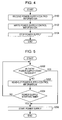
- FIG. 4 is a flowchart of the power supply stop processing performed by the power supply control apparatus 100 in Fig. 1 .
- the communication unit 118 of the power supply control apparatus 100 receives power-supply-control information from the electric device A 200 (step S100).
- the power-supply-control information includes opening/closing unit information and power supply starting time information.
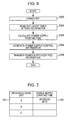
- Fig. 7 illustrates an example of a table of power-supply-control information written in the power-supply-control information storage unit 114.
- opening/closing unit information 700 and power supply starting time information 702 are written in the table of the power-supply-control information.
- the power supply starting time with respect to the opening/closing unit A 104 is March 25, 2010, 20:15. When current time becomes March 25, 2010, 20:15, power supply to the electric device A 200 which is connected with the opening/closing unit A 104 is started as described later.
- control unit 110 transmits a control signal for making the opening/closing unit A 104 stop the power supply, to the opening/closing unit A 104, and the opening/closing unit A 104 stops the power supply to the electric device A 200 (step S104), ending the processing.
- the power supply to the electric device A 200 is stopped when the electric device A 200 transmits the power-supply-control information to the power supply control apparatus 100, being able to eliminate generation of standby power without degrading user's convenience.
- FIG. 5 is a flowchart of the power supply start processing performed by the power supply control apparatus 100 in Fig. 1 .
- a power-supply-start request detection unit 800 as the power-supply-start request detection unit 116 includes a button 802 indicating the opening/closing unit A 104, a button 804 indicating the opening/closing unit B 106, and a button 806 indicating the opening/closing unit C 108.
- the button 802 is pressed by a user, for example, power supply to the electric device A 200 which is connected with the opening/closing unit A 104 is started as described later.
- control unit 110 reads out the power-supply-control information from the power-supply-control information storage unit 114 (step S202).
- control unit 110 determines whether current time is on the power supply starting time or later, based on the power supply starting time information included in the power-supply-control information read out in step S202 and current time information supplied from the clock unit 112 (step S204).
- step S204 When the current time is not on the power supply starting time or later in consequence of the determination in step S204, that is, when the current time is time before the power supply starting time (NO in step S204), the processing returns to step S200.
- the control unit 110 transmits a control signal for making the opening/closing unit A 104 start the power supply, to the opening/closing unit A 104 and the opening/closing unit A 104 starts the power supply to the electric device A 200 (step S206), ending the processing.
- the power supply start processing of Fig. 5 when there is a start request of power supply to the electric device A 200 made by a user, or when the current time is on the power supply starting time or later, the power supply to the electric device A 200 is started, being able to eliminate generation of standby power without degrading user's convenience.
- the electric device A 200 reads out the timer time information from the storage unit 214, and starts a predetermined operation when the current time becomes the timer time, based on the timer time information which is read out and the current time information supplied from the clock unit 206.
- step S202 the control unit 110 reads out the power-supply-control information from the power-supply-control information storage unit 114, but may read out only power supply starting time information included in the power-supply-control information from the power-supply-control information storage unit 114.
- FIG. 6 is a flowchart showing the power-supply-control information transmission processing performed by the electric device A 200 in Fig. 1 .
- step S300 when the electric device A 200 is powered off by a user (step S300), the control unit 208 of the electric device A 200 reads out the latest timer setting information from the storage unit 214 (step S302).
- the control unit 208 calculates power supply starting time for the electric device A 200 to be in a standby state on timer time, based on the timer time information included in the timer setting information read out in step S302 and time information of time necessary from when the electric device A 200 is supplied with power to when the electric device A 200 becomes to be in the standby state (step S304). For example, the control unit 208 sets time which is earlier than the timer time by a time interval necessary from when the electric device A 200 is supplied with power to when the electric device A 200 becomes to be in the standby state, as power supply starting time.
- the control unit 208 calculates March 25, 2010, 20:15 as the power supply starting time.
- Fig. 9 illustrates an example of the power-supply-control information.
- power-supply-control information 900 includes opening/closing unit information 902 and power supply starting time information 904.
- Fig. 9 when current time becomes March 25, 2010, 20:15, power supply to the electric device A 200 which is connected with the opening/closing unit A 104 is started as described above.
- the communication unit 210 of the electric device A 200 transmits the power-supply-control information which is generated by the control unit 208 in step S306 to the power supply control apparatus 100 (step S308), ending the processing.
- power-supply-control information transmission processing of Fig. 6 when the electric device A 200 is powered off by a user, power-supply-control information is transmitted to the power supply control apparatus 100. As described above, when the power-supply-control information is transmitted to the power supply control apparatus 100, power supply to the electric device A 200 is stopped, being able to eliminate generation of standby power without degrading user's convenience.
- step S306 power-supply-control information including opening/closing unit information and power supply stating time information is generated.
- power-supply-control information including opening/closing unit information and timer time information may be generated.
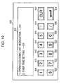
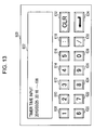
- FIG. 10 to 13 illustrate the opening/closing unit designation and the timer time setting by a user performed in the electric device A 200 of Fig. 1 .
- a user input unit 600 serving as the user input unit 212 includes a display unit 602 showing information to a user, buttons 608, 610, 612, 614, 616, 618, 620, 622, 624, 626, 628, and 630 which are used by a user for inputting information, a button 632 which is used by the user for deleting information that the user partially inputs, and a button 634 which is used for determining the information which is inputted by the user.
- the display unit 602 displays "1. OPENING/CLOSING UNIT DESIGNATION” 604 for designating the opening/closing unit A 104 to which the electric device A 200 is connected and "2. TIMER TIME SETTING" 606 for setting timer time on which the electric device A 200 conducts a predetermined operation, as information that can be inputted by the user.
- the opening/closing unit designation can be performed by pressing the button 608, and the timer time setting can be performed by pressing the button 610.
- the display unit 602 displays a display for promoting designation of an opening/closing unit, "1. OPENING/CLOSING UNIT A" 636 by which the user designates the opening/closing unit A 104, and the like.
- the opening/closing unit A can be designated by pressing the button 608.
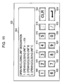
- Fig. 11 when the user presses the button 608 to designate the opening/closing unit A, the control unit 208 makes the storage unit 214 store opening/closing unit information as information of the opening/closing unit A which is designated by the user. Then, information displayed on the display unit 602 is returned to be the information shown in Fig. 10 .
- the display unit 602 displays a display for promoting an input of timer time.
- time and date can be inputted by pressing the buttons 608, 610, 612, 614, 616, 618, 620, 622, 624, 626, 628, and 630.
- Fig. 13 illustrates a case where a user inputs March 25, 2010, 20:18 as timer time.
- the display unit 602 displays a display promoting an input of timer time and "2010/03/25 20:18" 638 as inputted timer time.
- the display can be returned to the state shown in Fig. 12 by pressing the button 632. Further, in Fig. 13 , when the button 634 is pressed, inputted information can be determined.
- the control unit 208 makes the storage unit 214 store the timer time information, which is inputted by the user, as information of timer time. Then, the information displayed on the display unit 602 returns to the information shown in Fig. 10 .
- the opening/closing unit information and the timer time information are stored as timer setting information. That is, the timer setting information includes the opening/closing unit information and the timer time information, and the timer setting information is stored in the storage unit 214 at timing on which the timer time information is stored in the storage unit 214.
- the user does not have to designate an opening/closing unit every time, but if the user once designates an opening/closing unit, information of the opening/closing unit which is previously designated is used in the timer time setting.
- the user can easily designate an opening/closing unit and set timer time.
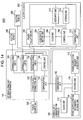
- FIG. 14 is a block diagram showing the configuration of a power supply control system according to the other embodiment of the present technology.
- the power supply control system according to the other embodiment of the present technology has the same configuration as that of the power supply control system of the embodiment described above except that the power supply control apparatus 100 is separated to an opening/closing unit control apparatus 140 and a power supply administration apparatus 180. Therefore, descriptions of duplicate configurations and functions are omitted, and different configurations and functions are described below.
- this power supply control system 2000 includes the opening/closing unit control apparatus 140, the power supply administration apparatus 180, an electric device A 200, an electric device B 300, an electric device C 400, and a power source unit 500.
- the opening/closing unit control apparatus 140 includes a power source connection unit 102, an opening/closing unit A 104, an opening/closing unit B 106, an opening/closing unit C 108, a communication unit 142, and a control unit 144.
- the communication unit 142 can receive a control signal which is transmitted from the power supply administration apparatus 180 and is used for making the opening/closing unit A 104 stop power supply and a control signal which is used for making the opening/closing unit A 104 start the power supply.
- the control unit 144 can control respective units of the opening/closing unit control apparatus 140. Further, the control unit 144 can transmit the control signal received by the communication unit 142 to the opening/closing unit A 104 and the like.
- the power supply administration apparatus 180 includes a control unit 110, a clock unit 112, a power-supply-control information storage unit 114, a power-supply-start request detection unit 116, and a communication unit 182.
- the control unit 110 can control respective units of the power supply administration apparatus 180.
- the communication unit 182 can receive power-supply-control information transmitted from the electric device A 200, for example. Further, the communication unit 182 can transmit a control signal for making the opening/closing unit A 104 stop power supply, and a control signal for making the opening/closing unit A 104 start the power supply, for example, to the opening/closing unit control apparatus 140.
- a communication unit 210 of the electric device A 200 can transmit power-supply-control information to the power supply administration apparatus 180, for example.
- the opening/closing unit control apparatus 140 and the power supply administration apparatus 180 perform the power supply stop processing described above with reference to Fig. 4 and the power supply start processing described above with reference to Fig. 5 , and the electric device A 200 performs the power-supply-control information transmission processing described above with reference to Fig. 6 , being able to provide the same advantageous effect as that in the embodiment described first.
- the power supply control system 2000 can be realized.
- the embodiment can be easily performed.
- the respective embodiments of the present technology may be realized such that a storage medium storing program codes of software for realizing the functions of the respective embodiments described above is supplied to a system or an apparatus, and a computer (or a CPU, an MPU, and the like) of the system or the apparatus reads out and performs the program codes stored in the storage medium.
- the program codes which are read out from the storage medium realize the functions of the respective embodiments described above, and the program codes and the storage medium storing the program codes constitute the embodiments of the present technology.
- Examples of the storage medium for supplying program codes include a floppy® disk, a hard disk, a magnet-optical disk, an optical disk such as a CD-ROM, a CD-R, a CD-RW, a DVD-ROM, a DVD-RAM, a DVD-RW, and a DVD+RW, a magnetic tape, a nonvolatile memory card, a ROM, and the like.
- program codes may be downloaded through a network.
- the functions of the respective embodiments described above are realized by performing the program code which is read out by the computer.
- the functions of the respective embodiments described above are realized by performing a part or a whole of actual processing by an operating system (OS) or the like operating on the computer, based on a direction of the program code.
- OS operating system
- a CPU or the like provided to the expansion board or the expansion unit performs a part or a whole of actual processing of the expansion function, based on the direction of the program code.
Landscapes
- Engineering & Computer Science (AREA)
- Power Engineering (AREA)
- Remote Monitoring And Control Of Power-Distribution Networks (AREA)
- Direct Current Feeding And Distribution (AREA)
- Selective Calling Equipment (AREA)
- Power Sources (AREA)
Applications Claiming Priority (1)
| Application Number | Priority Date | Filing Date | Title |
|---|---|---|---|
| JP2010221549A JP2012080626A (ja) | 2010-09-30 | 2010-09-30 | 電力供給制御装置、電気機器、電力供給制御システム、電力供給制御方法およびプログラム |
Publications (1)
| Publication Number | Publication Date |
|---|---|
| EP2437376A2 true EP2437376A2 (de) | 2012-04-04 |
Family
ID=44674083
Family Applications (1)
| Application Number | Title | Priority Date | Filing Date |
|---|---|---|---|
| EP11007113A Withdrawn EP2437376A2 (de) | 2010-09-30 | 2011-09-01 | Vorrichtung zur Leistungsversorgungssteuerung, elektrische Vorrichtung, System zur Leistungsversorgungssteuerung und Programm zur Leistungsversorgungssteuerung |
Country Status (5)
| Country | Link |
|---|---|
| US (1) | US20120084581A1 (de) |
| EP (1) | EP2437376A2 (de) |
| JP (1) | JP2012080626A (de) |
| KR (1) | KR20120033985A (de) |
| CN (1) | CN102445910A (de) |
Cited By (1)
| Publication number | Priority date | Publication date | Assignee | Title |
|---|---|---|---|---|
| CN104007679A (zh) * | 2014-05-29 | 2014-08-27 | 美的集团股份有限公司 | 电源连接器、用电设备及其控制方法和控制装置 |
Families Citing this family (2)
| Publication number | Priority date | Publication date | Assignee | Title |
|---|---|---|---|---|
| JP5328445B2 (ja) * | 2008-05-02 | 2013-10-30 | キヤノン株式会社 | 情報処理装置及び情報処理装置の制御方法 |
| CN104578395A (zh) * | 2013-10-18 | 2015-04-29 | 宁夏先锋软件有限公司 | 一种电网的智能控制系统 |
Citations (2)
| Publication number | Priority date | Publication date | Assignee | Title |
|---|---|---|---|---|
| JP2003110471A (ja) | 2001-09-26 | 2003-04-11 | Sanyo Electric Co Ltd | 電力線接続機器制御システム及び接続装置 |
| JP2010221549A (ja) | 2009-03-24 | 2010-10-07 | Fujifilm Corp | インクジェット記録媒体の製造方法 |
Family Cites Families (15)
| Publication number | Priority date | Publication date | Assignee | Title |
|---|---|---|---|---|
| US5153580A (en) * | 1990-01-16 | 1992-10-06 | Rca Thomson Licensing Corporation | Retriggerable sleep timer with user-prompting mode operation |
| US6211581B1 (en) * | 1997-11-28 | 2001-04-03 | Harvard M. Farrant | Power bar with remote control |
| JP3963692B2 (ja) * | 2001-10-15 | 2007-08-22 | 富士通株式会社 | 複数の情報処理装置の電源制御方法、その情報処理装置、及びプログラム |
| CN2752872Y (zh) * | 2004-11-24 | 2006-01-18 | 上海广电(集团)有限公司中央研究院 | 家用电器电源节能装置 |
| GB2452112B (en) * | 2005-06-21 | 2009-05-20 | One Click | Socket assembly with data traffic sensing |
| US7657763B2 (en) * | 2005-12-29 | 2010-02-02 | Panasonic Electric Works Co., Ltd. | Systems and methods for selectively controlling electrical outlets using power profiling |
| CN201063382Y (zh) * | 2006-12-15 | 2008-05-21 | 上海久隆电力科技有限公司 | 一种家用电器智能待机节电插座 |
| TW200840358A (en) * | 2007-03-16 | 2008-10-01 | Benq Corp | Method for managing a scheduling system and related scheduling system |
| KR100992294B1 (ko) * | 2008-02-29 | 2010-11-05 | 김선영 | 콘센트 |
| EP2274811A4 (de) * | 2008-04-22 | 2013-01-02 | Belkin International Inc | Verbesserte stromversorgung |
| US8305249B2 (en) * | 2008-07-18 | 2012-11-06 | EchoStar Technologies, L.L.C. | Systems and methods for controlling power consumption in electronic devices |
| US8314517B2 (en) * | 2008-07-29 | 2012-11-20 | Honeywell International Inc. | Electric timer for controlling power to a load |
| KR20100030485A (ko) * | 2008-09-10 | 2010-03-18 | 엘지전자 주식회사 | 발전 수단을 갖는 대기 상태 제어장치 |
| CN201546062U (zh) * | 2009-09-25 | 2010-08-11 | 海尔集团公司 | 用于洗衣机的整机断电控制装置 |
| US8127126B2 (en) * | 2009-10-06 | 2012-02-28 | Li-Chun Lai | Integrated power supply and network connection control device for cord set |
-
2010
- 2010-09-30 JP JP2010221549A patent/JP2012080626A/ja not_active Withdrawn
-
2011
- 2011-09-01 EP EP11007113A patent/EP2437376A2/de not_active Withdrawn
- 2011-09-21 US US13/238,916 patent/US20120084581A1/en not_active Abandoned
- 2011-09-22 KR KR1020110095603A patent/KR20120033985A/ko not_active Withdrawn
- 2011-09-23 CN CN2011102869272A patent/CN102445910A/zh active Pending
Patent Citations (2)
| Publication number | Priority date | Publication date | Assignee | Title |
|---|---|---|---|---|
| JP2003110471A (ja) | 2001-09-26 | 2003-04-11 | Sanyo Electric Co Ltd | 電力線接続機器制御システム及び接続装置 |
| JP2010221549A (ja) | 2009-03-24 | 2010-10-07 | Fujifilm Corp | インクジェット記録媒体の製造方法 |
Cited By (1)
| Publication number | Priority date | Publication date | Assignee | Title |
|---|---|---|---|---|
| CN104007679A (zh) * | 2014-05-29 | 2014-08-27 | 美的集团股份有限公司 | 电源连接器、用电设备及其控制方法和控制装置 |
Also Published As
| Publication number | Publication date |
|---|---|
| CN102445910A (zh) | 2012-05-09 |
| KR20120033985A (ko) | 2012-04-09 |
| US20120084581A1 (en) | 2012-04-05 |
| JP2012080626A (ja) | 2012-04-19 |
Similar Documents
| Publication | Publication Date | Title |
|---|---|---|
| EP2177969B1 (de) | Bildanzeigevorrichtung mit Funktion zum Laden einer externen Vorrichtung und Ladeverfahren dafür | |
| EP2888867B1 (de) | Übergabe von medieninhalten zwischen einer mobilen vorrichtung und einer externen vorrichtung | |
| EP3342157B1 (de) | Informationsverarbeitungsvorrichtung, bildaufnahmegerät, informationsverarbeitungssystem, informationsverarbeitungsverfahren und programm | |
| US20080242369A1 (en) | Portable electronic apparatus | |
| KR20150099891A (ko) | 데이터 변환 처리 방법 및 이를 지원하는 전자 장치 | |
| CN102915289A (zh) | 数据传输方法 | |
| US20150363188A1 (en) | Information Processing Device and Information Processing System | |
| CN109951893A (zh) | 一种终端设备唤醒方法及装置 | |
| EP2437376A2 (de) | Vorrichtung zur Leistungsversorgungssteuerung, elektrische Vorrichtung, System zur Leistungsversorgungssteuerung und Programm zur Leistungsversorgungssteuerung | |
| US9384752B2 (en) | Audio device and storage medium | |
| US20080015807A1 (en) | Transferring data in a portable electronic device | |
| US20100214479A1 (en) | Broadcasting receiving apparatus | |
| JP2009129111A (ja) | 無線通信機器、認証方法、及び無線接続制御方法 | |
| US20120227079A1 (en) | Distribution system | |
| JP2006011865A (ja) | 携帯電話端末電源供給システム | |
| CN107211363B (zh) | 一种蓝牙开关控制方法及智能手环、移动终端 | |
| US8576798B2 (en) | Data communication apparatus and data communication method thereof | |
| CN118300217A (zh) | 充电线缆的控制方法及其装置 | |
| US10439416B2 (en) | Method for outputting charging current according to displayed media and power amplifier | |
| US20180113829A1 (en) | Electronic apparatus and coupling method | |
| EP2259165A2 (de) | Statusdikriminierende Vorrichtung und Verfahren | |
| CN113746982A (zh) | 一种音频播放控制方法、装置、电子设备和可读存储介质 | |
| CN101932137A (zh) | 具有多种无线通讯功能的电子系统及其通讯模块操作方法 | |
| JP2007279834A (ja) | 認証システム、認証方法 | |
| CN106020406B (zh) | 一种控制方法、连接器及电子设备 |
Legal Events
| Date | Code | Title | Description |
|---|---|---|---|
| PUAI | Public reference made under article 153(3) epc to a published international application that has entered the european phase |
Free format text: ORIGINAL CODE: 0009012 |
|
| 17P | Request for examination filed |
Effective date: 20110901 |
|
| AK | Designated contracting states |
Kind code of ref document: A2 Designated state(s): AL AT BE BG CH CY CZ DE DK EE ES FI FR GB GR HR HU IE IS IT LI LT LU LV MC MK MT NL NO PL PT RO RS SE SI SK SM TR |
|
| AX | Request for extension of the european patent |
Extension state: BA ME |
|
| STAA | Information on the status of an ep patent application or granted ep patent |
Free format text: STATUS: THE APPLICATION HAS BEEN WITHDRAWN |
|
| 18W | Application withdrawn |
Effective date: 20151203 |