EP2437260A2 - Tonsignalverarbeitungsvorrichtung - Google Patents
Tonsignalverarbeitungsvorrichtung Download PDFInfo
- Publication number
- EP2437260A2 EP2437260A2 EP11179183A EP11179183A EP2437260A2 EP 2437260 A2 EP2437260 A2 EP 2437260A2 EP 11179183 A EP11179183 A EP 11179183A EP 11179183 A EP11179183 A EP 11179183A EP 2437260 A2 EP2437260 A2 EP 2437260A2
- Authority
- EP
- European Patent Office
- Prior art keywords
- sound
- signal
- section
- signals
- level
- Prior art date
- Legal status (The legal status is an assumption and is not a legal conclusion. Google has not performed a legal analysis and makes no representation as to the accuracy of the status listed.)
- Granted
Links
Images


Classifications
-
- G—PHYSICS
- G10—MUSICAL INSTRUMENTS; ACOUSTICS
- G10L—SPEECH ANALYSIS TECHNIQUES OR SPEECH SYNTHESIS; SPEECH RECOGNITION; SPEECH OR VOICE PROCESSING TECHNIQUES; SPEECH OR AUDIO CODING OR DECODING
- G10L21/00—Speech or voice signal processing techniques to produce another audible or non-audible signal, e.g. visual or tactile, in order to modify its quality or its intelligibility
- G10L21/02—Speech enhancement, e.g. noise reduction or echo cancellation
- G10L21/0272—Voice signal separating
-
- G—PHYSICS
- G10—MUSICAL INSTRUMENTS; ACOUSTICS
- G10H—ELECTROPHONIC MUSICAL INSTRUMENTS; INSTRUMENTS IN WHICH THE TONES ARE GENERATED BY ELECTROMECHANICAL MEANS OR ELECTRONIC GENERATORS, OR IN WHICH THE TONES ARE SYNTHESISED FROM A DATA STORE
- G10H1/00—Details of electrophonic musical instruments
- G10H1/0091—Means for obtaining special acoustic effects
-
- G—PHYSICS
- G10—MUSICAL INSTRUMENTS; ACOUSTICS
- G10H—ELECTROPHONIC MUSICAL INSTRUMENTS; INSTRUMENTS IN WHICH THE TONES ARE GENERATED BY ELECTROMECHANICAL MEANS OR ELECTRONIC GENERATORS, OR IN WHICH THE TONES ARE SYNTHESISED FROM A DATA STORE
- G10H2210/00—Aspects or methods of musical processing having intrinsic musical character, i.e. involving musical theory or musical parameters or relying on musical knowledge, as applied in electrophonic musical tools or instruments
- G10H2210/155—Musical effects
- G10H2210/265—Acoustic effect simulation, i.e. volume, spatial, resonance or reverberation effects added to a musical sound, usually by appropriate filtering or delays
- G10H2210/281—Reverberation or echo
-
- G—PHYSICS
- G10—MUSICAL INSTRUMENTS; ACOUSTICS
- G10H—ELECTROPHONIC MUSICAL INSTRUMENTS; INSTRUMENTS IN WHICH THE TONES ARE GENERATED BY ELECTROMECHANICAL MEANS OR ELECTRONIC GENERATORS, OR IN WHICH THE TONES ARE SYNTHESISED FROM A DATA STORE
- G10H2250/00—Aspects of algorithms or signal processing methods without intrinsic musical character, yet specifically adapted for or used in electrophonic musical processing
- G10H2250/131—Mathematical functions for musical analysis, processing, synthesis or composition
- G10H2250/215—Transforms, i.e. mathematical transforms into domains appropriate for musical signal processing, coding or compression
- G10H2250/235—Fourier transform; Discrete Fourier Transform [DFT]; Fast Fourier Transform [FFT]
-
- G—PHYSICS
- G10—MUSICAL INSTRUMENTS; ACOUSTICS
- G10L—SPEECH ANALYSIS TECHNIQUES OR SPEECH SYNTHESIS; SPEECH RECOGNITION; SPEECH OR VOICE PROCESSING TECHNIQUES; SPEECH OR AUDIO CODING OR DECODING
- G10L21/00—Speech or voice signal processing techniques to produce another audible or non-audible signal, e.g. visual or tactile, in order to modify its quality or its intelligibility
- G10L21/02—Speech enhancement, e.g. noise reduction or echo cancellation
- G10L21/0208—Noise filtering
- G10L2021/02082—Noise filtering the noise being echo, reverberation of the speech
-
- G—PHYSICS
- G10—MUSICAL INSTRUMENTS; ACOUSTICS
- G10L—SPEECH ANALYSIS TECHNIQUES OR SPEECH SYNTHESIS; SPEECH RECOGNITION; SPEECH OR VOICE PROCESSING TECHNIQUES; SPEECH OR AUDIO CODING OR DECODING
- G10L21/00—Speech or voice signal processing techniques to produce another audible or non-audible signal, e.g. visual or tactile, in order to modify its quality or its intelligibility
- G10L21/02—Speech enhancement, e.g. noise reduction or echo cancellation
- G10L21/0208—Noise filtering
- G10L2021/02087—Noise filtering the noise being separate speech, e.g. cocktail party
-
- G—PHYSICS
- G10—MUSICAL INSTRUMENTS; ACOUSTICS
- G10L—SPEECH ANALYSIS TECHNIQUES OR SPEECH SYNTHESIS; SPEECH RECOGNITION; SPEECH OR VOICE PROCESSING TECHNIQUES; SPEECH OR AUDIO CODING OR DECODING
- G10L21/00—Speech or voice signal processing techniques to produce another audible or non-audible signal, e.g. visual or tactile, in order to modify its quality or its intelligibility
- G10L21/02—Speech enhancement, e.g. noise reduction or echo cancellation
- G10L21/0272—Voice signal separating
- G10L21/028—Voice signal separating using properties of sound source
-
- G—PHYSICS
- G10—MUSICAL INSTRUMENTS; ACOUSTICS
- G10L—SPEECH ANALYSIS TECHNIQUES OR SPEECH SYNTHESIS; SPEECH RECOGNITION; SPEECH OR VOICE PROCESSING TECHNIQUES; SPEECH OR AUDIO CODING OR DECODING
- G10L21/00—Speech or voice signal processing techniques to produce another audible or non-audible signal, e.g. visual or tactile, in order to modify its quality or its intelligibility
- G10L21/02—Speech enhancement, e.g. noise reduction or echo cancellation
- G10L21/0272—Voice signal separating
- G10L21/0308—Voice signal separating characterised by the type of parameter measurement, e.g. correlation techniques, zero crossing techniques or predictive techniques
Definitions
- the present invention relates to a sound signal processing device and, in particular embodiments, to a sound signal processing device which can suitably extract main sound from mixed sound in which unnecessary sounds are mixed with the main sound.
- Performance sound of multiple musical instruments playing one musical composition may be recorded for each of the musical instruments independently in a live performance or the like.
- the recorded sound of each of the musical instruments is composed of mixed sound in which performance sound of each of the musical instruments is mixed with performance sound of the other musical instruments called "leakage sound.”
- the recorded sound of each of the musical instruments is processed (for example, delayed), the presence of leakage sound may become problem, and it is desired to remove such leakage sound from the recorded sound.
- sound recorded with a microphone generally includes original sound and its reverberation components (reverberant sound).
- reverberant sound Several technical methods have been proposed to attempt to remove reverberant sound from mixed sound in which original sound is mixed with the reverberant sound. For example, according to one of such methods, a waveform of pseudo reverberant sound corresponding to reverberant sound is generated, and the waveform of the pseudo reverberant sound is deducted from the original mixed sound on the time axis (for example, see Japanese Laid-open Patent Application HEI 07-154306 ).
- a phase-inverted wave of reverberant sound is generated from mixed sound, and is emanated from an auxiliary speaker to be mixed with the mixed sound in a real field, thereby cancelling out the reverberant sound (see, for example, Japanese Laid-open Patent Application HEI 06-062499 ).
- the present applicant proposed a technology to extract, from signals of mixed sounds in which multiple musical sounds are mixed together, the musical sounds at plural localization positions, based on levels of the signals in the frequency domain (for example, Japanese Patent Application 2009-277054 (unpublished)).
- Embodiments of the present invention relate to a sound signal processing device that is capable of suitably extracting main sound from mixed sound in which unnecessary sound (for example, leakage sound and reverberant sound) is mixed with the main sound.
- unnecessary sound for example, leakage sound and reverberant sound
- a mixed sound signal is a signal in the time domain of mixed sound including first sound and second sound.
- a target sound signal is a signal in the time domain of sound including sound corresponding to at least the second sound.
- a range of level ratios indicative of the first sound is pre-set for each of the frequency bands. Then, a judging device judges as to whether or not the level ratio calculated by the level ratio calculating device is within the set range. Further, from among signals corresponding to the mixed sound signal, a signal in a frequency band which is judged by the judging device to be in the range is extracted by an extracting device. In this manner, the signal of the first sound included in the mixed sound signal can be extracted. Accordingly, from the mixed sound in which unnecessary sound as the second sound is mixed with the main sound as the first sound, the main sound being the first sound can be extracted.
- the unnecessary sound may be, for example, leakage sound, sound migrated in due to deterioration of a recording tape, reverberant sound, and the like.
- the first sound is extracted from the mixed sound (in other words, the second sound is excluded), while focusing on their frequency characteristics and level ratios.
- the first sound can be readily extracted with good sound quality.
- the main sound can be suitably extracted from a mixed sound in which unnecessary sound is mixed with the main sound.
- a time difference that is generated based on a difference in sound generation timing between the first sound and the second sound included in the mixed sound is adjusted by an adjusting device. More specifically, the signal inputted from the first input device (the mixed sound signal) or the signal inputted from the second input device (the target sound signal) is adjusted by delaying it on the time axis by an adjustment amount according to the time difference.
- the time difference is a time difference between the signal of the second sound in the mixed sound signal and the signal of the second sound in the target sound signal. Therefore, by the adjustment performed by the adjusting device, the signal of the second sound in the mixed sound signal and the signal of the second sound in the target sound signal can be matched with each other on the time axis.
- a "time difference” may be generated, for example, based on a difference between the characteristic of the sound field space between the first output source that outputs the first sound and the sound collecting device, and the characteristic of the sound field space between the second output source that outputs the second sound and the sound collecting device.
- a "time difference” may occur, for example, when a cassette tape that records sounds is deteriorated, and signals of second sound that are time-sequentially different from first signals of first sound recorded at a certain time are transferred onto the signals of the first sound in a portion of overlapped segments of the wound tape.
- the signals of the second sound not only include signals of sound that are recorded later in time, but also include signals of sound that are recorded earlier in time.
- a "time difference” includes the case where no time difference exists (in other words, a time difference of zero). Further, an "adjustment amount according to a time difference” may include no adjustment (in other words, an adjustment amount of zero).
- the main sound can be suitably extracted from mixed sound in which unnecessary sound (for example, leakage sound, transferred noise due to deterioration of a recording tape, and the like) is mixed in main sound.
- a second extracting device extracts a signal, from signals corresponding to the mixed sound signal among the adjusted signal or the original signal in a frequency band, with the level ratio that is judged to be outside of the pre-set range. Therefore, signals of sound corresponding to the second sound included in the mixed sound can be extracted and outputted. By extracting and outputting signals of sound corresponding to the second sound included in the mixed sound, the user can hear which sound is removed from the mixed sound. By this, information for properly extracting the first sound can be provided.
- first sound recorded in a predetermined track can be extracted from among multitrack data.
- multitrack data of performance sounds of a plurality of musical instruments performing one musical composition which may be recorded in a live concert or the like independently from one musical instrument to another
- signals of sound recorded in a track that records sound of a target musical instrument or human voice are inputted in a first input device.
- signals of sounds recorded in other tracks that record sounds other than the sound of the target musical instrument or human voice included in the sounds recorded in the specified track are inputted in the second input device. In this manner, the sound of the target musical instrument or human voice from which leakage sound is removed can be extracted.
- an adjusted signal is generated based on a delay time as the adjustment amount according to the position of each of the second output sources and the number of second output sources. Therefore, the signal of the second sound in the mixed sound signal and the signal of the second sound in the target sound signal can be matched with each other with high accuracy, and the first sound can be extracted with good sound quality.
- an input device inputs, as the mixed sound signal, a signal in the time domain of mixed sound including first sound outputted from a predetermined output source and second sound generated based on the first sound in a sound field space, where the first and second sounds are collected and obtained by a single sound collecting device.
- a pseudo signal generation device delays the signal of the mixed sound on the time axis according to an adjustment amount determined according to a time difference between a time at which the first sound is collected by a sound collecting device and a time at which the second sound is collected by the same sound collecting device. By this, a signal of the second sound as the target sound signal is pseudo-generated from the signal of the mixed sound.
- the main sound (for example, original sound) can be suitably extracted from mixed sound in which unnecessary sound (for example, reverberant sound or the like) is mixed with the main sound.
- the original sound from the mixed sound which is inputted through the input device and includes the first sound as the original sound and reverberant sound (the second sound).
- delay times generated according to the reverberation characteristic in a sound field space are used as the adjustment amount, each of which is a delay time from the time when the first sound is collected by the sound collection device to the time when reverberant sound generated based on the first sound is collected by the sound collection device. Then, based on the delay times as the adjustment amount, and the number set for reflection positions that reflect the first sound in the sound field space, a signal of early reflection is generated as a pseudo signal of the second sound. Therefore, signals of early reflection can be accurately simulated, such that the original sound (the first sound) can be extracted with good sound quality.
- a present level of the pseudo signal of the second sound is compared with a previous level thereof.
- a level correction device corrects the level of the pseudo signal of the second sound to be used in the level ratio calculation device to the level obtained by multiplying the previous level with the predetermined attenuation coefficient. Therefore, rapid attenuation of the level of the pseudo signal of the second sound can be dulled. In other words, rapid changes in the level ratios calculated by the level ratio calculation device can be suppressed. As a result, reflected sounds with a relatively lower level that follow the arrival of reflected sounds that occur from sounds with great volume level can be captured.
- level ratios calculated by the level ratio calculation device are corrected such that, the smaller the level of the mixed sound signal, the smaller the ratio of the mixed sound signal with respect to the level of the pseudo signal of the second sound. Therefore, it is possible to make signals of mixed sound with lower levels to be readily judged as the second sound. As a result, late reverberant sound can be captured.
- FIG. 1 is a block diagram showing a configuration of an effector (an example of a sound signal processing device) in accordance with an embodiment of the invention.
- FIG. 2 is a functional block diagram showing functions of a DSP.
- FIG. 3 is a functional block diagram showing functions of a multiple track generation section.
- FIG. 4 (a) is a functional block diagram showing functions of a delay section.
- FIG. 4 (b) is a schematic graph showing impulse responses to be convoluted with an input signal by the delay section shown in FIG. 4 (a) .
- FIG. 5 is a schematic diagram with functional blocks showing a process executed by the respective components composing a first processing section.
- FIG. 6 is a schematic diagram showing an example of a user interface screen displayed on a display screen of a display device.
- FIG. 7 is a block diagram showing a composition of an effector in accordance with a second embodiment of the invention.
- FIG. 8 is a functional block diagram showing functions of a DSP in accordance with the second embodiment.
- FIG. 9 (a) is a block diagram showing functions of an Lch early reflection component generation section.
- FIG. 9 (b) is a schematic diagram showing impulse responses to be convoluted with an input signal by the Lch early reflection component generation section shown in FIG. 9 (a) .
- FIG. 10 is a schematic diagram with functional blocks showing a process to be executed by an Lch component discrimination section.
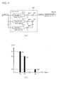
- FIG. 11 is an explanatory diagram that compares an instance when attenuation of
- FIG. 12 is a schematic diagram showing an example of a user interface screen displayed on a display screen of a display device.
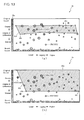
- FIGS. 13 (a) and (b) are diagrams showing modified examples of the range set in a signal display section.
- FIG. 14 is a block diagram showing a configuration of an all-pass filter.
- FIG. 1 is a block diagram showing a configuration of an effector 1 (an example of a sound signal processing device) in accordance with the first embodiment of the invention.
- an effector 1 an example of a sound signal processing device
- the effector 1 when performance sounds of multiple musical instruments performing a single musical composition are recorded on multiple tracks with each track used for recording a respective musical instrument, the effector 1 removes leakage sound included in recorded sounds on each track.
- musical instruments described in the present specification is deemed to include vocals.
- the effector 1 includes a CPU 11, a ROM 12, a RAM 13, a digital signal processor (hereafter referred to as a "DSP") 14, a D/A for Lch 15L, a D/A for Rch 15R, a display device I/F 16, an input device I/F 17, HDD_I/F 18, and a bus line 19.
- the "D/A” is a digital to analog converter.
- Each of the sections 11 - 14, 15L, 15R and 16 - 18 are electrically connected with one another through the bus line 19.
- the CPU 11 is a central control unit that controls each of the sections connected through the bus line 19 according to fixed values and control programs stored in the ROM 12 or the like.
- the ROM 12 is a non-rewritable memory that stores a control program 12a or the like to be executed by the effector 1.
- the control program 12a includes a control program for each process to be executed by the DSP 14 that is to be described below with reference to FIGS. 2 - 5 .
- the RAM 13 is a memory that temporarily stores various kinds of data.
- the DSP 14 is a device for processing digital signals.
- the DSP 14 in accordance with an embodiment of the present invention executes processes as described in greater detail below.
- the DSP 14 performs multitrack reproduction of multitrack data 21a stored in the HDD 21.
- the DSP 14 discriminates sound signals of the main sound intended to be recorded in the track from sound signals of leakage sound recorded mixed with the main sound.
- the sound intended to be recorded is performance sound of a musical instrument designated by the user, and this sound may be called hereafter "main sound.”
- the DSP 14 extracts the signals of the discriminated main sound as "leakage-removed sound” and outputs the same to the Lch D/A 15L and the Rch D/A 15R.
- the Lch D/A 15L is a converter that converts left-channel signals that were signal processed by the DSP 14, from digital signals to analog signals. The analog signals, after conversion, are outputted through an OUT_L terminal.
- the Rch D/A 15R is a converter that converts right-channel signals that were signal-processed by the DSP 14, from digital signals to analog signals. The analog signals, after conversion, are outputted through an OUT_R terminal.
- the display device I/F 16 is an interface for connecting with the display device 22.
- the effector 1 is connected to the display device 22 through the display device I/F 16.
- the display device 22 may be a device having a display screen of any suitable type, including, but not limited to an LCD display, LED display, CRT display, plasma display or the like.
- a user-interface screen 30 to be described below with reference to FIG. 6 is displayed on the display screen of the display device 22.
- the user-interface screen will be hereafter referred to as a "UI screen.”
- the input device I/F 17 is an interface for connecting with an input device 23.
- the effector 1 is connected to the input device 23 through the input device I/F 17.
- the input device 23 is a device for inputting various kinds of execution instructions to be supplied to the effector 1, and may include, for example, but not limited to, a mouse, a tablet, a keyboard, a touch-panel, button, rotary or slide operators, or the like.
- the input device 23 may be configured with a touch-panel that senses operations made on the display screen of the display device 22.
- the input device 23 is operated in association with the UI screen 30 (see FIG. 6 ) displayed on the display screen of the display device 22. Accordingly, various kinds of execution instructions may be inputted, for extracting leakage-removed sounds from recorded sounds on a track that records performance sounds of a musical instrument designated by the user.
- the HDD_I/F 18 is an interface for connecting with an HDD 21 that may be an external hard disk drive.
- the HDD 21 stores one or a plurality of multitrack data 21a.
- One of the multitrack data 21a selected by the user is inputted for processing to the DSP 14 through the HDD_I/F 18.
- the multitrack data 21a is audio data recorded in multiple tracks.
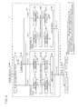
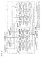
- FIG. 2 is a functional block diagram showing functions of the DSP 14.
- Functional blocks formed in the DSP 14 include a multitrack reproduction section 100, a delay section 200, a first processing section 300, and a second processing section 400.
- the multitrack reproduction section 100 reproduces, in multitrack format, the multitrack data 2 1 a stored on the HDD 21.
- the multitrack reproduction section 100 can provide a signal IN_P [t] that is a reproduced signal based on recorded sounds on a track that records performance sounds of a musical instrument designated by the user.
- the multitrack reproduction section 100 inputs the signal IN_P [t] to a first frequency analysis section 310 of the first processing section 300 and a first frequency analysis section 410 of the second processing section 400.
- [t] denotes a signal in the time domain.
- the multitrack reproduction section 100 inputs IN_B [t], which is a reproduced signal based on performance sounds recorded on tracks other than the track designated by the user, to the delay section 200. Further details of the multitrack reproduction section 100 will be described below with reference to FIG. 3 .
- the delay section 200 delays the signal IN_B [t] supplied from the multitrack reproduction section 100 by a delay time according to a setting selected by the user, and multiplies the signal with a predetermined level coefficient (a positive number of 1.0 or less). If there are multiple sets of the pair of a delay time and a level coefficient set by the user, all the results are added up.
- a delayed signal IN_Bd [t] thus obtained by the above processes is inputted in a second frequency analysis section 320 of the first processing section 300 and a second frequency analysis section 420 of the second processing section 400. Details of the delay section 200 will be described below with reference to FIG. 4 .
- the first processing section 300 and the second processing section 400 repeatedly and respectively execute common processings at predetermined time intervals, with respect to IN_P[t] supplied from the multitrack reproduction section 100 and IN_Bd [t] supplied from the delay section 200. In this manner, each of the first processing section 300 and the second processing section 400 outputs either a signal P[t] of leakage-removed sound, or a signal B[t] of leakage sound.
- the signals, P[t] or B[t] outputted from each of the first processing section 300 and the second processing section 400 are mixed by cross-fading, and outputted as OUT_P[t] or OUT_B[t], respectively.
- the first processing section 300 includes the first frequency analysis section 310, the second frequency analysis section 320, a component discrimination section 330, a first frequency synthesis section 340, a second frequency synthesis section 350 and a selector section 360.
- the first frequency analysis section 310 converts IN_P[t] supplied from the multitrack reproduction section 100 to a signal in the frequency domain, and converts the same from a Cartesian coordinate system to a polar coordinate system.
- the first frequency analysis section 310 outputs a signal POL _1 [f] in the frequency domain expressed in the polar coordinate system to the component discrimination section 330.
- the second frequency analysis section 320 converts IN_Bd[t] supplied from the delay section 200 to a signal in the frequency domain, and converts the same from a Cartesian coordinate system to a polar coordinate system.
- the second frequency analysis section 320 outputs a signal POL _2[f] in the frequency domain expressed in the polar coordinate system to the component discrimination section 330.
- the component discrimination section 330 obtains a ratio between an absolute value of the radius vector of POL_1[f] supplied from the first frequency analysis section 310 and an absolute value of the radius vector of POL_2[f] supplied from the second frequency analysis section 320 (hereafter this ratio is referred to as the "level ratio"). Then, the component discrimination section 330 compares the obtained ratio at each frequency f with the range of level ratios pre-set for the frequency f. Further, POL_3[f] and POL_4[f] set according to the comparison result are outputted to the first frequency synthesis section 340 and the second frequency synthesis section 350, respectively.
- the first frequency synthesis section 340 converts POL_3[f] supplied from the component discrimination section 330 from the polar coordinate system to the Cartesian coordinate system, and converts the same to a signal in the time domain. Further, the first frequency synthesis section 340 outputs the obtained signal P[t] in the time domain expressed in the Cartesian coordinate system to the selector section 360.
- the second frequency synthesis section 350 converts POL_4[f] supplied from the component discrimination section 330 from the polar coordinate system to the Cartesian coordinate system, and converts the same to a signal in the time domain. Further, the first frequency synthesis section 350 outputs the obtained signal B[t] in the time domain expressed in the Cartesian coordinate system to the selector section 360.
- the selector section 360 outputs either the signal P[t] supplied from the first frequency synthesis section 340 or the signal B[t] supplied from the second frequency synthesis section 350, based on a designation by the user.
- P[t] is a signal of a leakage-removed sound, that is, of recorded sound from which unnecessary leakage sound is removed in a track that records sound of a musical instrument designated by the user.
- B[t] is a signal of leakage sound.
- the first processing section 300 can extract and output P[t] that is a signal of leakage-removed sound or B[t] that is a signal of leakage sound, in response to a designation by the user.
- the second processing section 400 includes the first frequency analysis section 410, the second frequency analysis section 420, a component discrimination section 430, a first frequency synthesis section 440, a second frequency synthesis section 450 and a selector section 460.
- Each of the sections 410 - 460 composing the second processing section 400 functions in a similar manner as each of the sections 310 - 360 composing the first processing section 300, respectively, and outputs the same signal. More specifically, the first frequency analysis section 410 functions like the first frequency analysis section 310, and outputs POL _1[f].
- the second frequency analysis section 420 functions like the second frequency analysis section 320, and outputs POL _2[f].
- the component discrimination section 430 functions like the component discrimination section 330, and outputs POL_3[f] and POL_4[f].
- the first frequency analysis section 440 functions like the first frequency analysis section 340, and outputs P[t].
- the second frequency analysis section 450 functions like the second frequency analysis section 350, and outputs B[t].
- the selector section 460 functions like the selector section 360, and outputs either P[t] or B[t].
- the execution interval of the processes executed by the second processing section 400 is the same as the execution interval of the processes executed by the first processing section 300. However, the processes executed by the second processing section 400 are started a predetermined time later, after starting of execution of processing by the first processing section 300. By this, the process executed by the second processing section 400 fills up a joining section from the completion of execution until the start of execution between each processing by the first processing section 300. On the other hand, the process executed by the first processing section 300 fills up a joining section from the completion of execution until the start of execution between each processing by the second processing section 400.
- the first processing section 300 and the second processing section 400 execute their processing every 0.1 seconds. Also, a process to be executed by the second processing section 400 is started 0.05 seconds later (a half cycle later) from the start of execution of the process by the first processing section 300. It is noted, however, that the execution interval of the first processing section 300 and the second processing section 400 and the delay time from the start of execution of a process by the first processing section 300 until the start of execution of the process by the second processing section 400 are not limited to 0.1 seconds and 0.05 seconds exemplified above, and may be of any suitable values according to the sampling frequency and the number of musical sound signals.
- FIG. 3 is a functional block diagram showing functions of the multitrack reproduction section 100.
- the multitrack reproduction section 100 is configured with first - n-th track reproduction sections 101-1 through 101-n, n first multipliers 102a-1 through 102a-n, n second multipliers 102b-1 through 102b-n, a first adder 103a and a second adder 103b, where n is an integer greater than 1.
- the first-n-th track reproduction sections 101-1 through 101-n execute multitrack reproduction through synchronizing and reproducing single track data composing the multitrack data 21a.
- Each of the "single track data" is audio data recorded on one track.
- Each of the track reproduction sections 101-1 through 101-n synchronizes and reproduces one or plural single track data of recorded performance sound of one musical instrument from among the sets of single track data composing the multitrack data 21a.
- Each of the track reproduction sections 101-1 through 101-n outputs a monaural reproduced signal of the performance sound of the musical instrument.
- Each track reproduction section is not necessarily limited to reproducing one single track data. For example, when performance sounds of one musical instrument are recorded in stereo on multiple tracks, reproduced sounds of sets of the single track data respectively corresponding to the multiple tracks are mixed and outputted as a monaural reproduced signal.
- the track reproduction sections 101-1 through 101-n output the monaural reproduced signals to the corresponding respective first multipliers 102a-1 through 102a-n, and the corresponding respective second multipliers 102b-1 through 102b-n.
- the first multipliers 102a-1 through 102a-n multiply the reproduced signals inputted from the corresponding track reproduction sections 101-1 through 101-n by coefficients S1 through Sn, respectively, and output the signals to the first adder 103a.
- the coefficients S1 through Sn are each a positive number of 1 or less.
- the second multipliers 102b-1 through 102b-n multiply the reproduced signals inputted from the corresponding track reproduction sections 101-1 through 101-n by coefficients (1 - S1) through (1 - Sn), respectively, and output the signals to the first adder 103a.
- the first adders 103a add all the signals outputted from the first multipliers 102a-1 through 102a-n.
- the first adders 103a obtain a signal IN_P[t] and input that signal to the first frequency analysis section 310 of the first processing section 300 and the first frequency analysis section 410 of the second processing section 400, respectively.
- the second adders 103b add all the signals outputted from the second multipliers 102b-1 through 102b-n.
- the second adders 103b obtain a signal IN_B[t] and input that signal to the delay section 200.
- the user may designate sound of one musical instrument to be extracted as leakage-removed sound on the UI screen 30 to be described below (see FIG. 6 ).
- the values of the coefficients S1 - Sn used by the first multipliers 102a-1 through 102a-n are specified depending on whether sounds of a musical instrument to be reproduced by the corresponding track reproduction sections 101-1 through 101-n are the sounds of the musical instrument designated by the user. More specifically, the values of the coefficients S1 - Sn corresponding to those of the track reproduction sections 101-1 through 101-n that mainly include sounds of the musical instrument designated as the leakage-removed sound are set at 1.0. The values of the coefficients S1 - Sn corresponding to the other track reproduction sections are set at 0.0.
- the values of the coefficients used by the second multipliers 102b-1 through 102b-n are decided according to the values of the corresponding coefficients S1 - Sn.
- the coefficients S1 - Sn used by the first multipliers 102a-1 through 102a-n are 1.0
- the coefficients (1 - S1) through (1 - Sn) to be used by the second multipliers 102b-1 through 102b-n are set at 0.0.
- the coefficients S1 - Sn are 0.0
- the corresponding coefficients (1 - S1) through (1 - Sn) are set at 1.0.
- the multitrack reproduction section 100 outputs to the first frequency analysis sections 310 and 410 as IN_P[t], the reproduced signals outputted from those of the track reproduction sections 101-1 through 101-n that mainly include sounds of the musical instrument designated as the leakage-removed sound.
- the reproduced signals outputted from the other track reproduction sections are not included in IN_P[t].
- the multitrack reproduction section 100 outputs the reproduced signals outputted from those of the track reproduction sections that mainly include sounds of musical instruments other than the sounds of the musical instrument designated as the leakage-removed sound to the delay section 200 as IN_B[t].
- the reproduced signals outputted from the track reproduction sections 101-1 through 101-n designated as the leakage-removed sound are not included in IN_B[t].
- IN_P[t] outputted from the multitrack reproduction section 100 to the first frequency analysis sections 310 and 410 is composed of mixed sounds of the main sound and unnecessary sounds (leakage sounds that overlap the main sound).
- the main sound corresponds to a signal of the vocal sound (Vo[t]).
- the unnecessary sounds correspond to signals in which the signals of mixed sounds B[t] of the sounds of the other musical instruments are changed by the characteristic Ga[t] of the sound field space.
- IN_P[t] Vo[t] + Ga [ B[t] ].
- IN_B[t] outputted from the multitrack reproduction section 100 to the delay section 200 corresponds to signals of unnecessary sounds (B[t]).
- B[t] corresponds to signals of mixed sounds including a signal of performance sound of a guitar (Gtr[t]), a signal of performance sound of a keyboard (Kbd[t]), a signal of performance sound of drums (Drum[t]) and the like
- IN_B[t] corresponds to the sum of the sound signals of those musical instruments.
- IN_B[t] Gtr[t] + Kbd[t] + Drum[t] + ....
- FIG. 4(a) is a functional block diagram showing functions of the delay section 200.
- the delay section 200 is an FIR filter, and includes first through N-th delay elements 201-1 through 201-N, N multipliers 202-1 through 202-N, and an adder 203, where N is an integer greater than 1.
- the delay elements 201-1 through 201-N are elements that delay the input signal IN_B[t] by delay times T1 - TN respectively specified for each of the delay elements.
- the delay elements 201-1 through 201-N output the delayed signals to the corresponding multipliers 202-1 through 202-N, respectively.
- the multipliers 202-1 through 202-N multiply the signals supplied from the corresponding delay elements 201-1 through 201-N by level coefficients C1 - CN (all of them being a positive number of 1.0 or less), respectively, and output the signals to the adders 203.
- the adders 203 add all the signals outputted from the multipliers 202-1 through 202-N.
- the adders 203 obtain a signal IN_Bd[t] and input that signal to the second frequency analysis section 320 of the first processing section 300 and the second frequency analysis section 420 of the second processing section 400, respectively.
- the number of the delay elements 201-1 through 201-N (i.e., N) in the delay section 200, the delay times T1 - TN, and the level coefficients C 1 - CN are suitably set by the user.
- the user operates a delay time setting section 34 in the UI screen 30 (see FIG. 6 ) as described below to set these values.
- the delay times T1 - TN at least one of the delay times may be zero (in other words, no delay is set).
- the number of the delay elements 201-1 through 201-N may be set to the number of output sources of leakage sound, and the delay times T1 - TN and the level coefficients C1 - CN may be set for the respective delay elements, whereby impulse responses Ir1 - IrN shown in FIG. 4(b) can be obtained. By convolution of these impulse responses Ir1 - IrN with IN-B[t], IN_Bd[t] is generated.
- a sound collecting device e.g., a microphone or the like
- the sound collecting device collects sound of a musical instrument (i.e., the main sound) to be recorded on the track, as well as sounds other than the main sound.
- Output sources of those sounds are output sources of leakage sounds, which may be, for example, loudspeakers, musical instruments such as drums, and the like.
- Z is a transfer function of Z-transform, and indexes of the transfer function Z (-m1, -m2, ... -mN) are decided according to the delay times T1 - TN, respectively.
- the delay times are decided based on the distance from the respective speakers to the vocal microphone.
- FIG. 4(b) is a graph schematically showing impulse responses to be convoluted with the input signal (i.e., IN_B[t]) at the delay section 200 shown in FIG. 4 (a) .
- the horizontal axis represents time
- the vertical axis represents levels.
- the first impulse response Ir1 is an impulse response with the level C1 at the delay time T1
- the second impulse response Ir2 is an impulse response with the level C2 at the delay time T2.
- the N-th impulse response IrN is an impulse response with the level CN at the delay time TN.
- each of the impulse responses Ir1, Ir2, ... IrN reflects Ga[t] that expresses the characteristic of the sound field space.
- the impulse responses Ir1, Ir2, ... IrN can be obtained by setting the number N of the delay elements, the delay times T1 - TN, and the level coefficients C1 - CN, using the UI screen 30.
- an IN_Bd[t] that suitably simulates the leakage sound component (Ga[B [t]]) included in IN-P[t] can be generated and outputted.
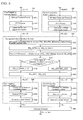
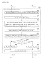
- FIG. 5 schematically shows, with functional blocks, processes executed by each of the sections 310 - 360 of the first processing section 300.
- Each of the sections 410 - 460 of the second processing section 400 executes processes similar to those of the sections 310 - 360 shown in FIG. 5 .
- the first frequency analysis section 310 executes a process of multiplying IN_P[t] supplied from the multitrack reproduction section 100 with a window function (S311).
- a Hann window is used as the window function.
- the windowed signal IN_P[t] is subjected to a fast Fourier transform (FFT) (S312).
- FFT fast Fourier transform
- IN_P[t] is transformed into IN_P[f], which represents spectrum signals plotted versus Fourier-transformed frequency f as abscissas.
- IN_P[f] is transformed into a polar coordinate system (S313). More specifically, Re[f] + jIm[f] at each frequency f is transformed into r[f] (cos (arg[f])) + jr[f] (sin (arg[f])).
- POL_1[f] outputted from the first frequency analysis section 310 to the component discrimination section 330 is r[f] (cos (arg[f])) + jr[f] (sin (arg[f])) that is obtained by the process in S313.
- the second frequency analysis section 320 executes a windowing with respect to IN_Bd[t] supplied from the delay section 200 (S321), executes an FFT process (S322), and executes a transformation into the polar coordinate system (S323).
- the processing contents of the processes in S321 - S323 that are executed by the second frequency analysis section 320 are generally the same as those processes in S311- S313 described above, except that the processing target IN_P[t] changes to IN_Bd[t]. Accordingly, description of the details of these processes is omitted.
- the output signal of the second frequency analysis section 320 becomes POL_2[f], because the processing target is changed to IN_Bd[t].
- the component discrimination section 330 compares the radius vector of POL_1[f] with the radius vector of POL_2[f], and sets, as Lv[f], the absolute value of the radius vector with a greater absolute value (S331).
- Lv[f] set in S331 is supplied to the CPU 11, and is used for controlling the display of the signal display section 36 of the UI screen (see FIG. 6 ) to be described below.
- the degree of difference [f] presents a value that expresses the degree of difference between the input signal (IN_P[t]) corresponding to POL_1[f] and the input signal (i.e., IN_Bd[t] that is a delay signal of IN_B[t]) corresponding to POL_2[f].
- the degree of difference [f] is limited to a range between 0.0 and 2.0. In other words, when
- exceeds 2.0, the degree of difference [f] 2.0.
- the degree of difference [f] also equals to 2.0.
- the degree of difference [f] calculated in S333 will be used in processes in S334 and thereafter, and supplied to the CPU 11 and used for controlling the signal display section 36 on the UI screen (see FIG. 6 ) to be described below.
- the "range set at the frequency f" is the range of degrees of difference [f] at a certain frequency f in which sounds are determined to be leakage-removed sounds (or sounds to be extracted as P[t]).
- the range of degrees of difference [f] is set by the user, using the UI screen 30 (see FIG. 6 ) to be described below. Therefore, when the degree of difference [f] at a frequency f is within the set range, it means that POL_1[f] at that frequency is a signal of leakage-removed sound.
- POL_3[f] is set to POL_1[f] (S335); and when it is negative (S334: No), POL_4[f] is set to POL_1[f] (S336). Therefore, POL_3[f] is a signal corresponding to leakage-removed sound extracted from POL_1[f]. On the other hand, POL_4[f] is a signal corresponding to leakage sound extracted from POL_1[f].
- POL_3[f] at each frequency f is outputted to the first frequency synthesis section 340, and POL_4[f] at each frequency f is outputted to the second frequency synthesis section 350 (S337).
- the first frequency synthesis section 340 first transforms, at each frequency f, POL_3[f] supplied from the component discrimination section 330 into a Cartesian coordinate system (S341).
- r[f] (cos (arg[f])) +jr[f](sin(arg[f])) at each frequency f is transformed into Re[f] +jIm[f].
- r[f](cos(arg[f])) is set as Re[f]
- jr[f](sin(arg[f])) is set as jIm[f], thereby performing the transformation.
- Re[f] r[f](cos(arg[f]))
- jIm[f] jr[f] (sin(arg[f])).
- a reverse fast Fourier transform (reverse FFT) is applied to the signals of the Cartesian coordinate system (i.e., the signals in complex numbers) obtained in S341, thereby obtaining signals in the time domain (S342).
- the signals obtained are multiplied by the same window function as the window function used in the process in S311 by the frequency analysis section 310 described above (S343). Further, the signals obtained are outputted as P[t] to the selector section 360.
- the Hann window is also used in the process in S343.
- the second frequency synthesis section 350 transforms, for each frequency f, POL_4[f] supplied from the component discrimination section 330 into a Cartesian coordinate system (S351), executes a reverse FFT process (S352), and executes a windowing (S353).
- the processes in S351 - S353 that are executed by the second frequency synthesis section 350 are similar to those processes in S341 - S343 described above, except that the signal POL_3[f] supplied from the component discrimination section 330 changes to POL_4[f]. Accordingly, description of the details of these processes is omitted.
- the output signal of the second frequency synthesis section 350 becomes B[t], instead of P[t], because the signal supplied from the component discrimination section 330 changes to POL_4[f].
- POL_3[f] are signals corresponding to leakage-removed sound extracted from POL_1[f]. Therefore, P[t] outputted from the first frequency synthesis section 340 to the selector section 360 are signals in the time domain of the leakage-removed sound.
- POL_4[f] are signals corresponding to leakage sound extracted from POL_1[f]. Therefore, B[t] outputted from the second frequency synthesis section 350 to the selector section 360 are signals in the time domain of the leakage sound.
- the selector section 360 outputs either P[t] supplied from the first frequency synthesis section 340 or B[t] supplied from the second frequency synthesis section 350 in response to a designation by the user.
- the designation by the user is performed on the UI screen 30 to be described below with reference to FIG. 6 .
- Either the signal P[t] or B[t] is outputted from the selector section 360 of the first processing section 300.
- the selector section 460 of the second processing section 400 outputs P[t] or B[t], which is the same kind of signal outputted from the selector section 360. These signals are mixed together, and the mixed signals are outputted to D/A 15L and D/A 15R.
- the effector 1 of the present embodiment can output sound without leakage sound (where leakage sound has been removed) from a track that records sound of a musical instrument designated by the user, as the main sound. Also, depending on a condition designated by the user, sound corresponding to leakage sound in that case can be outputted.
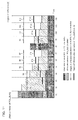
- FIG. 6 is a schematic diagram showing an example of a UI screen 30 displayed on the display screen of the display device 22.
- the UI screen 30 includes a track display section 31, a selection button 32, a transport button 33, a delay time setting section 34, a switching button 35 and a signal display section 36.
- the track display section 31 is a screen that displays audio waveforms recorded in single track data sets included in the multitrack data 21a. When one multitrack data 21a intended to be processed by the user is selected, audio waveforms are displayed in the track display section 31 separately for each of the single track data sets. In the example shown in FIG. 6 , five display sections 31a-31e are displayed.
- the display sections 31a, 31b and 31e are screens for displaying audio waveforms of the tracks that record in monaural vocal sounds, guitar sounds and drums sounds as main sounds, respectively.
- the display sections 31c and 31d are screens for displaying waveforms of sounds on the respective left and right channels of keyboard sounds that are recorded in stereo.
- the horizontal axis corresponds to the time and the vertical axis corresponds to the amplitude.
- the selection buttons 32 include buttons for designating sound of musical instruments to be extracted as leakage-removed sound. Each of the selection buttons 32 is provided for each musical instrument that emanates the main sound on each of the single track data sets of the multitrack data 21a. In the example shown in FIG. 6 , four selection buttons 32 are provided. More specifically, there are a selection button 32a corresponding to vocal sound (vocalist), a selection button 32b corresponding to guitar sound (guitar), a selection button 32c corresponding to keyboard sound (keyboard), and a selection button 32d corresponding to drums sound (drums).
- vocal sound vocal sound
- guitar guitar sound
- keyboard sound keyboard
- selection button 32d corresponding to drums sound
- the selection buttons 32 can be operated by the user, using the input device 23 (for example, a mouse).
- a specified operation for example, a click operation
- the selection button is placed in a selected state, and the musical instrument corresponding to the selection button in the selected state is selected as a musical instrument that is subjected to removal of leakage sound.
- the musical instruments corresponding to the remaining selection buttons are selected as musical instruments that are designated as leakage sound sources.
- the coefficient corresponding to the musical instrument that is subjected to leakage sound removal is set at 1.0, and the remaining coefficients are set at 0.0.
- the selection button 32a is in the selected state (a character display of "Leakage-removed Sound” in a color, tone, highlight or other user-detectable state indicating that the button is selected).
- the vocal sound is selected as being subjected to removal of leakage sound.
- the other selection buttons 32b - 32d are in the non-selected state (a character display of "Leakage Sound” in a color, tone, highlight or other user-detectable state indicating that the buttons are not selected).
- the guitar sound, the keyboard sound and the drums sound are selected as being designated as leakage sound.
- the transport button 33 includes a group of buttons for manipulating the multitrack data 21a to be processed.
- the transport button 33 includes, for example, a play button for reproducing the multitrack data 21a in multitracks, a stop button for stopping reproduction, a fast forward button for fast forwarding reproduced sound or data, a rewind button for rewinding reproduced sound or data, and the like.
- the transport button 33 can be operated by the user, using the input device 23 (for example, a mouse). In other words, each button in the group of buttons included in the transport button 33 can be operated by applying a specified operation (for example, a click operation) to that button.
- the delay time setting section 34 is a screen for setting parameters to be used to delay IN_B[t] at the delay section 200.
- the delay time setting section 34 screen has a horizontal axis that corresponds to time and a vertical axis that corresponds to the level.
- the delay time setting section 34 displays bars 34a that are set by the user through operating the input device 23.
- the number of bars 34a corresponds to the number N of output sources of leakage sound.
- the user can suitably add or erase these bars by performing a predetermined operation using the input device 23 (for example, a mouse).
- the predetermined operation may be, for example, clicking the right button on the mouse to select the operation in a displayed menu.
- three bars 34a are displayed, which means that "3" is set as the number N of output sources of leakage sound.
- the switching button 35 includes buttons 35a and 35b that are used to designate signals outputted from the selector sections 360 and 460 to be signals of leakage-removed sound (P[t]) or signals of leakage sound (B[t]).
- the button 35a is a button for designating signals of leakage-removed sound (P[t])
- the button 35b is a button for designating signals of leakage sound (B[t]).
- the switching button 35 may be operated by the user, using the input device 23 (for example a mouse).
- the button 35a or the button 35b is operated (for example, clicked)
- the clicked button is placed in a selected state, whereby signals corresponding to the button are designated as signals to be outputted from the selector sections 360 and 460.
- the button 35a is in the selected state (is in a color, tone, highlight or other user-detectable state indicating that the button is selected). More specifically, signals of leakage-removed sound (P[t]) are designated (selected) as signals to be outputted from the selector section 360 and 460.
- the button 35b is in a non-selected state (in a color, tone, highlight or other user-detectable state indicating that the button is not selected).
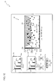
- the signal display section 36 is a screen for visualizing input signals to the effector 1 (in other words, input signals from the multitrack data 21a) on a plane of the frequency f versus the degree of difference [f].
- the degree of difference [f] represents values indicating the degree of difference between IN_P[t] and IN_Bd[t] that represents delay signals of IN_B[t].
- the horizontal axis of the signal display section 36 represents the frequency f, which becomes higher toward the right, and lower toward the left.
- the vertical axis represents the degree of difference [f], which becomes greater toward the upper side, and smaller toward the bottom side.
- the vertical axis is appended with a color bar 36a that expresses the magnitude of the degree of difference [f] with different colors.
- the signal display section 36 displays circles 36b each having its center at a point defined according to the frequency f and the degree of difference [f] of each input signal.
- the coordinates of these points are calculated by the CPU 11 based on values calculated in the process S333 by the component discrimination section 330.
- the circles 36b are colored with colors in the color bar 36a respectively corresponding to the degrees of difference [f] indicated by the coordinates of the centers of the circles.
- the radius of each of the circles 36b represents Lv[f] of an input signal of the frequency f, and the radius becomes greater as Lv[f] becomes greater.
- Lv[f] represents values calculated by the process in S331 (by the component discrimination section 330). Therefore, the user can intuitively recognize the degree of difference [f] and Lv[f] by the colors and the sizes (radius) of the circles 36b displayed in the signal display section 36.
- a plurality of designated points 36c displayed in the signal display section 36 are points that specify the range of settings used for the judgment in S334 by the component discrimination section 330.
- a boundary line 36d is a linear line connecting adjacent ones of the designated points 36c, and a line that specifies the border of the setting range.
- An area 36e surrounded by the boundary line 36d and the upper edge (i.e., the maximum value of the degree of difference [f]) of the signal display section 36 defines the range of settings used for the judgment in S334 by the component discrimination section 330.
- the number of the designated points 36c and initial values of the respective positions are stored in advance in the ROM 12.
- the user may use the input device 23 to increase or decrease the number of the designated points 36c or to change their positions, whereby an optimum range of settings can be set.
- the input device 23 is a mouse
- the cursor may be placed on the boundary line 36d in proximity to an area where a designated point 36c is to be added, and the left button on the mouse may be depressed, whereby another designated point 36c can be added.
- the added designated point 36c is in the selected state, and can therefore be shifted to a suitable position by shifting the mouse while the left button is kept depressed.
- the cursor may be placed on any of the designated points 36c desired to be removed, and the right button on the mouse may be clicked to display a menu and select deletion in the displayed menu, whereby the specified designated point 36c can be deleted.
- the cursor may be placed on any of the designated points 36c desired to be moved, and the left button on the mouse may be clicked, whereby the specified designated points 36c can be placed in a selected state. In this state, by moving the mouse while the left button is being depressed, the selected designated point can be moved to a suitable position. The selected state may be released by releasing the left button.
- Signals corresponding to circles 36b1 among the circles 36b displayed in the signal display section 36, whose centers are included inside the range 36e (including the boundary), are judged in S334 by the component discrimination section 330 to be the signals whose degree of difference [f] at that frequency f are within the range of settings.
- signals corresponding to circles 36b2 whose centers are outside the range 36e are judged in S334 by the component discrimination section 330 to be the signals outside the range of settings.
- a track that records performance sound of a musical instrument among the multitrack data 21a is designated by the user.
- the delay section 200 delays IN_B[t], which represents reproduced signals of tracks other than the track designated by the user. Accordingly, it is possible to obtain IN_Bd[t] that is a signal assimilating the signal G[B[t]], which is the signal B[t] of leakage sound modified by the characteristic G[t] of the sound field space, included in the data IN_P[t] of the track designated by the user.
- the level ratio, at each frequency f, between the signals respectively obtained by frequency analysis of IN_Bd[t] and IN_P[t] expresses the degree of difference between these two signals.
- the higher the level ratio the more signal components that are not included in IN_Bd[t] (in other words, signals of leakage-removed sound P[t] included in IN_P[t]). Therefore, the level ratios can be used as indexes for discriminating signals of leakage-removed sound (P[t]) included in IN_P[t] from signals of leakage sound B[t].
- signals of leakage-removed sound P[t] can be extracted from IN_P[t], according to the level ratios.
- leakage sound (B[t]) can be extracted from IN_P[t]. Therefore, this makes it possible for the user to hear which sounds are removed from IN_P[t], and thus, user-perceptible information for properly extracting P[t] can be provided.
- the effector 1 is capable of extracting leakage-removed sound in which leakage sound is removed from recorded sound of a track that records performance sound of one musical instrument as the main sound.
- An effector 1 in accordance with a further embodiment is capable of removing reverberant sound from sound collected by a single sound collecting device (for example, a microphone).
- a single sound collecting device for example, a microphone
- FIG. 7 is a block diagram showing the configuration of the effector 1 in accordance with the further embodiment.
- the effector 1 in accordance with the further embodiment includes a CPU 11, a ROM 12, a RAM 13, a DSP 14, an A/D for Lch 20L, an A/D for Rch 20R, a D/A for Lch 15L, a D/A for Rch 15R, a display device I/F 16, an input device I/F 17, and a bus line 19.
- the "A/D" is an analog to digital converter.
- the components 11- 14, 15L, 15R, 16, 17, 20L and 20R are electrically connected with one another through the bus line 19.
- a control program 12a stored in the ROM 12 includes a control program for each process to be executed by the DSP 14 described below with reference to FIGS. 8-10 .
- the Lch A/D 20L is a converter that converts left-channel signals inputted from an IN_L terminal from analog signals to digital signals.
- the Rch A/D 20R is a converter that converts right-channel signals inputted from an IN_R terminal from analog signals to digital signals.
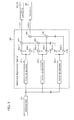
- FIG. 8 is a functional block diagram showing functions of the DSP 14 in accordance with the further embodiment.
- Left and right channel signals are inputted in the DSP 14 from one sound collecting device (for example, a microphone) through the Lch A/D 20L and the Rch A/D 20R.
- the DSP 14 discriminates signals of the original sound from signals of reverberant sound generated by sound reflection in the sound field space from the left and right channel signals inputted. Further, the DSP 14 extracts either the signal of the original sound or the signal of the reverberant sound selected, and outputs the same to the Lch D/A 15L and the Rch D/A 15R.
- the functional blocks formed in the DSP 14 include an Lch early reflection component generation section 500L, an Rch early reflection component generation section 500R, a first processing section 600, and a second processing section 700.
- the Lch early reflection component generation section 500L generates a pseudo signal of early reflection sound IN_BL[t] included in the left channel sound from an input signal IN_PL[t] inputted from the Lch A/D 20L.
- the Lch early reflection component generation section 500L inputs the generated IN_BL[t] to a second Lch frequency analysis section 620L of the first processing section 600, and a second Lch frequency analysis section 720L of the second processing section 700, respectively. Details of functions of the Lch early reflection component generation section 500L will be described with reference to FIG. 9 below.
- the Rch early reflection component generation section 500R generates a pseudo signal of early reflection sound IN_BR[t] included in the right channel sound from an input signal IN_PR[t] inputted from the Rch A/D 20R.
- the Rch early reflection component generation section 500R inputs the generated IN_BR[t] to a second Rch frequency analysis section 620R of the first processing section 600, and a second Rch frequency analysis section 720R of the second processing section 700, respectively.
- the functions of the Rch early reflection component generation section 500R are similar to those of the Lch early reflection component generation section 500L described above. Therefore, the description, below (with reference to FIG. 9 ), of the functions of the Lch early reflection component generation section 500L, similarly applies for functions of the Rch early reflection component generation section 500R.
- the first processing section 600 and the second processing section 700 repeatedly execute common processing at predetermined time intervals, respectively, with respect to the input signal IN_PL[t] supplied from the Lch A/D 20L and IN_BL [t] supplied from the Lch early reflection component generation section 500L. Furthermore, the first processing section 600 and the second processing section 700 repeatedly execute common processing at predetermined time intervals, respectively, with respect to the input signal IN_PR[t] supplied from the Rch A/D 20R and IN_BR [t] supplied from the Rch early reflection component generation section 500R.
- signals OrL[t] and OrR[t] of the original sound in the two channels or signals BL[t] and BR[t] of reverberant sound are outputted.
- OrL[t] and OrR[t] or BL[t] and BR[t] outputted from each of the first processing section 600 and the second processing section 700 are mixed at each channel by cross-fading, and outputted as OUT_OrL[t] and OUT_OrR[t], or OUT_BL[t] and OUT_BR[t].
- OUT_OrL[t] and OUT_OrR[t] are outputted from the DSP 14
- these signals are inputted in the Lch D/A 15L and the Rch D/A 15R, respectively.
- OUT_BL[t] and OUT_BR[t] are outputted from the DSP 14, these signals are inputted in the Lch D/A 15L and the Rch D/A 15R, respectively.
- the first processing section 600 includes a first Lch frequency analysis section 610L, a second Lch frequency analysis section 620L, an Lch component discrimination section 630L, a first Lch frequency synthesis section 640L, a second Lch frequency synthesis section 650L, and an Lch selector section 660L. These components function to process left-channel input signals (IN_PL[t]) inputted from the Lch A/D 20L.
- the first Lch frequency analysis section 610L multiplies IN_PL[t] inputted from the Lch A/D 20L with a Hann window as a window function, executes a fast Fourier transform process (FFT process) to transform it to a signal in the frequency domain, and then transforms it into a polar coordinate system. Then, the first Lch frequency analysis section 610L outputs to the Lch component discrimination section 630L, the left-channel signal POL_IL[f] in the frequency domain expressed in the polar coordinate system thus obtained by the transformation.
- the first Lch frequency analysis section 610L receives an input IN_PL[t] instead, and its output accordingly changes to POL_1L[f]. Details of each of the processes other than the above which are executed by the first Lch frequency analysis section 610L are substantially the same as those of the processes executed in S311- S313 in the embodiment described above.
- the second Lch frequency analysis section 620L multiplies IN_BL[t] inputted from the Lch early reflection component generation section 500L with a Hann window as a window function, executes an FFT process to transform it to a signal in the frequency domain, and then transforms it into a polar coordinate system. Then, the second Lch frequency analysis section 620L outputs to the Lch component discrimination section 630L, the left-channel signal POL_2L[f] in the frequency domain expressed in the polar coordinate system thus obtained by the transformation.
- the second Lch frequency analysis section 620L receives IN_BL[t] instead, and its output accordingly changes to POL_2L[f]. Details of each of the processes other than the above which are executed by the second Lch frequency analysis section 620L are substantially the same as those of the processes executed in S321 - S323 in the embodiment described above.
- the Lch component discrimination section 630L obtains a ratio between an absolute value of the radius vector of POL_IL[f] supplied from the first Lch frequency analysis section 610L and an absolute value of the radius vector of POL_2L[f] supplied from the second Lch frequency analysis section 620L (i.e., a level ratio).
- the Lch component discrimination section 630L sets the left-channel signal of the original sound in the frequency domain expressed in the polar coordinate system to POL_3L[f] based on the obtained level ratio, and outputs the same to the first Lch frequency synthesis section 640L.
- the Lch component discrimination section 630L sets the left-channel signal of the reverberant sound in the frequency domain expressed in the polar coordinate system to POL_4L[f], and outputs the same to the second Lch frequency synthesis section 650L. Details of processes executed by the Lch component discrimination section 630L will be described below with reference to FIG. 10 .
- the first Lch frequency synthesis section 640L transforms POL_3L[f] supplied from the Lch component discrimination section 630L from the polar coordinate system to the Cartesian coordinate system, and then transforms the same to a signal in the time domain by executing a reverse fast Fourier transform process (a reverse FFT process). Then, the first Lch frequency synthesis section 640L multiplies the signal in the time domain with the same window function (the Hann window as described in the present embodiment) as used in the first Lch frequency analysis section 610L. Furthermore, the first Lch frequency synthesis section 640L outputs the obtained left-channel signal of the original sound OrL[t] in the time domain expressed in the Cartesian coordinate system to the Lch selector section 660L.
- a reverse fast Fourier transform process a reverse FFT process
- the first Lch frequency synthesis section 640L receives an input POL_3L[f] instead, and its output accordingly changes to OrL[t]. Details of each of the processes other than the above which are executed by the first Lch frequency analysis section 640L are substantially the same as those of the processes executed in S341 - S343 in the embodiment described above.
- the second Lch frequency synthesis section 650L transforms POL_4L[f] supplied from the Lch component discrimination section 630L from the polar coordinate system to the Cartesian coordinate system, and then transforms the same to a signal in the time domain through executing a reverse FFT process. Then, the second Lch frequency synthesis section 650L multiplies the signal in the time domain with the same window function (the Hann window in the present embodiment) as used in the second Lch frequency analysis section 620L. Then, the second Lch frequency synthesis section 650L outputs to the Lch selector section 660L , the obtained left-channel signal of the reverberant sound BL[t] in the time domain expressed in the Cartesian coordinate system.
- the second Lch frequency synthesis section 650L receives an input POL_4L[f] instead, and its output accordingly changes to BL[t]. Details of each of the processes other than the above which are executed by the second Lch frequency synthesis section 650L are substantially the same as those of the processes executed in S351 - S353 in the embodiment described above.
- the Lch selector section 660L outputs either OrL[t] supplied from the first Lch frequency synthesis section 640L or BL[t] supplied from the second Lch frequency synthesis section 650L in response to designation by the user. In other words, the Lch selector section 660L outputs either the left-channel signal of the original sound OrL[t] or the left-channel signal of the reverberant sound BL[t], according to designation by the user.
- the first processing section 600 includes, for functions for processing right-channel signals, a first Rch frequency analysis section 610R, a second Rch frequency analysis section 620R, an Rch component discrimination section 630R, a first Rch frequency synthesis section 640R, a second Rch frequency synthesis section 650R, and a Rch selector section 660R.
- the first Rch frequency analysis section 610R multiplies IN_PR[t] inputted from the Rch A/D 20R with a Hann window as a window function, executes a FFT process to transform it to a signal in the frequency domain, and then transforms it into a polar coordinate system.
- the first Rch frequency analysis section 610R outputs to the Rch component discrimination section 630R, the obtained right-channel signal POL_1R[f] in the frequency domain expressed in the polar coordinate system thus obtained by the transformation.
- the first Rch frequency analysis section 610R receives an input IN_PR[t] instead, and its output accordingly changes to POL_1R[f]. Details of each of the processes other than the above which are executed by the first Rch frequency analysis section 610R are substantially the same as those of the processes executed in S311 - S313 in the embodiment described above.
- the second Rch frequency analysis section 620R multiplies IN_BR[t] inputted from the Rch early reflection component generation section 500R with a Hann window as a window function, executes a FFT process to transform it to a signal in the frequency domain, and then transforms it into a polar coordinate system.
- the second Rch frequency analysis section 620R outputs to the Rch component discrimination section 630R, the right-channel signal POL_2R[f] in the frequency domain expressed in the polar coordinate system thus obtained by the transformation.
- the second Rch frequency analysis section 620R receives an input IN_BR[t] instead, and its output accordingly changes to POL_2R[f]. Details of each of the processes other than the above which are executed by the second Rch frequency analysis section 620R are substantially the same as those of the processes executed in S3 21 - S323 in the embodiment described above.
- the Rch component discrimination section 630R obtains a ratio between an absolute value of the radius vector of POL_1R[f] supplied from the first Rch frequency analysis section 610R and an absolute value of the radius vector of POL_2R[f] supplied from the second Rch frequency analysis section 620R (i.e., a level ratio).
- the Rch component discrimination section 630R sets the right-channel signal of the original sound in the frequency domain expressed in the polar coordinate system to POL_3R[f] based on the obtained level ratio, and outputs the same to the first Rch frequency synthesis section 640R.
- the Rch component discrimination section 630R sets the right-channel signal of the reverberant sound in the frequency domain expressed in the polar coordinate system to POL_4R[f], and outputs the same to the second Rch frequency synthesis section 650R.
- the Rch component discrimination section 630R receives inputs of right-channel signals POL_1R[f] and POL-2R[f] instead, and its outputs change to right-channel signals POL_3R[f] and POL_4R[f].
- the first Rch frequency synthesis section 640R transforms POL_3R[f] supplied from the Rch component discrimination section 630R from the polar coordinate system to the Cartesian coordinate system, then executes a reverse FFT process, and multiplies the signal with the same window function (the Hann window in the present embodiment) as used in the first Rch frequency analysis section 610R. Furthermore, the first Rch frequency synthesis section 640R outputs to the Rch selector section 660R, the obtained right-channel signal of the original sound OrR[t] in the time domain expressed in the Cartesian coordinate system. The first Rch frequency synthesis section 640R receives an input POL-3R[f] instead, and its output accordingly changes to OrR[t]. Details of each of the processes other than the above which are executed by the first Rch frequency analysis section 640R are substantially the same as those of the processes executed in S341 - S343 in the embodiment described above.
- the second Rch frequency synthesis section 650R transforms POL_4R[f] supplied from the Rch component discrimination section 630R from the polar coordinate system to the Cartesian coordinate system, executes a reverse FFT process, and multiplies the signal with the same window function (the Hann window in the present embodiment) as used in the second Rch frequency analysis section 620R. Then, the second Rch frequency synthesis section 650R outputs to the Rch selector section 660R, the obtained right-channel signal of the reverberant sound BR[t] in the time domain expressed in the Cartesian coordinate system. The second Rch frequency synthesis section 650R receives an input POL-4R[f] instead, and its output accordingly changes to BR[t]. Details of each of the processes other than the above which are executed by the second Rch frequency synthesis section 650R are substantially the same as those of the processes executed in S351 - S353 in the embodiment described above.
- the Rch selector section 660R outputs either OrR[t] supplied from the first Rch frequency synthesis section 640R or BR[t] supplied from the second Rch frequency synthesis section 650R in response to a designation by the user. In other words, the Rch selector section 660R outputs either the right-channel signal of the original sound OrR[t] or the right-channel signal of the reverberant sound BR[t], according to the designation by the user.
- the first processing section 600 processes input signals of left and right channels (IN_PL[t] and IN_PR[t]) inputted from the Lch A/D 20L and Rch A/D 20R, and is capable of outputting left and right channel signals of the original sound (OrL[t] and OrR[t]) or left and right channel signals of the reverberant sound (BL[t] and BR[t]), as the user desires.
- the second processing section 700 includes a first Lch frequency analysis section 710L, a second Lch frequency analysis section 720L, an Lch component discrimination section 730L, a first Lch frequency synthesis section 740L, a second Lch frequency synthesis section 750L, and an Lch selector section 760L. These sections function to process left-channel input signals (IN_PL[t]) inputted from the Lch A/D 20L.
- the sections 710L - 760L function in a similar manner as the sections 610L - 660L of the first processing section 600, respectively, and output the same signals.
- the first Lch frequency analysis section 710L functions like the first Lch frequency analysis section 610L, and outputs POL_1L[f].
- the second Lch frequency analysis section 720L functions like the second Lch frequency analysis section 620L, and outputs POL_2L[f].
- the Lch component discrimination section 730L functions like Lch component discrimination section 630L, and outputs POL_3L[f] and POL_4L[f].
- the first Lch frequency synthesis section 740L functions like the first Lch frequency synthesis section 640L, and outputs OrL[t].
- the second Lch frequency synthesis section 750L functions like the second Lch frequency synthesis section 650L, and outputs BL[t].
- the Lch selector section 760L functions like the Lch selector section 660L, and outputs either OrL[t] or BL[t].
- the second processing section 700 includes a first Rch frequency analysis section 710R, a second Rch frequency analysis section 720R, an Rch component discrimination section 730R, a first Rch frequency synthesis section 740R, a second Rch frequency synthesis section 750R, and an Rch selector section 760R. These components function to process right-channel input signals (IN_PR[t]) inputted from the Rch A/D 20R.
- the components 710R-760R function in a similar manner as the components 610R - 660R of the first processing section 600, respectively, and output the same signals.
- the first Rch frequency analysis section 710R functions like the first Rch frequency analysis section 610R, and outputs POL_1R[f].
- the second Rch frequency analysis section 720R functions like the second Rch frequency analysis section 620R, and outputs POL_2R[f].
- the Rch component discrimination section 730R functions like Rch component discrimination section 630R, and outputs POL_3R[f] and POL_4R[f].
- the first Rch frequency synthesis section 740R functions like the first Rch frequency synthesis section 640R, and outputs OrR[t].
- the second Lch frequency synthesis section 750R functions like the second Rch frequency synthesis section 650R, and outputs BR[t].
- the Rch selector section 760R functions like the Rch selector section 660R and outputs either OrR[t] or BR[t].
- the execution interval of the processes executed by the first processing section 600 is the same as the execution interval of the processes executed by the second processing section 700. In the present example, the execution interval is 0.1 second. Also, the processes executed by the second processing section 700 are started a predetermined time later (half a cycle which is 0.05 seconds later in the present example embodiment) from the start of execution of the respective processes by the first processing section 600. Any suitable values may be used as the execution interval of the processes by the first processing section 600 and the second processing section 700, and the delay time from the start of execution of the processes in the first processing section 600 until the start of execution of the processes in the second processing section 700, and such values may be defined based on the sampling frequency and the number of signals of musical sounds.
- FIG. 9(a) is a block diagram showing functions of the Lch early reflection component generation section 500L.
- the Lch early reflection component generation section 500L is a FIR filter, and configured with first through N-th delay elements 501L-1 through 501L-N, N multipliers 502L-1 through 502L-N, and an adder 503L, where N is an integer greater than 1.
- the delay elements 501L-1 through 501L-N are elements that delay left-channel signals IN_PL[t] by delay times TL1 - TLN respectively specified for each of the delay elements.
- the delay elements 501L-1 through 501L-N output signals obtained by delaying the delay times TL1 - TLN to the corresponding multipliers 502L-1 through 502L-N, respectively.
- the multipliers 502L-1 through 502L-N multiply the signals supplied from the corresponding delay elements 501L-1 through 501L-N by level coefficients CL1 - CLN (all of them being positive numbers of 1.0 or less), respectively, and output the signals to the adders 503L.
- the adders 503L add all the signals outputted from the multipliers 502L-1 through 502L-N. Then, the adders 503L input a signal IN_BL[t] thus obtained to the second Lch frequency analysis section 620L of the first processing section 600 and the second Lch frequency analysis section 720L of the second processing section 700, respectively.
- the number of the delay elements 501L-1 through 501L-N (i.e., N) in the Lch early reflection component generation section 500L, the delay time TL1 - TLN, and the level coefficients CL1 - CLN are suitably set by the user.
- the user operates an Lch early reflection pattern setting section 41L in an UI screen to be described below (see FIG. 12 ) to set these values.
- At least one of the delay times T1 - TN may be zero (in other words, no delay is set).
- the number of the delay elements 501L-1 through 501L-N may be set to the number of reflection positions in a sound field space, and the delay times TL1 - TLN and the level coefficients CL1 - CLN may be set for the respective delay elements, whereby impulse responses IrL1 - IrLN shown in FIG. 9(b) can be obtained. By convolution of these impulse responses IrL1 - IrLN with IN-PL[t], IN_BL[t] is generated.
- Z is a transfer function of Z-transform, and indexes of the transfer function Z (-m1, -m2, ... -mN) are decided according to the delay times TL1 - TLN, respectively.
- FIG. 9(b) is a graph schematically showing impulse responses to be convoluted with the input signal (i.e., IN_PL[t]) in the Lch early reflection component generation section 500L shown in FIG. 9(a) .
- the horizontal axis represents time
- the vertical axis represents levels.
- the first impulse response IrL1 is an impulse response with the level CL1 at the delay time TL1
- the second impulse response IrL2 is an impulse response with the level CL2 at the delay time TL2.
- the N-th impulse response IrLN is an impulse response with the level CLN at the delay time TLN.
- Each of the impulse responses IrL1, IrL2, ..., and IrLN reflects the reverberation characteristic Gb[t] of the sound field space.
- a left-channel signal IN_PL[t] of sound (in other words, sound inputted from the Lch A/D 20L) collected by a sound collecting device such as a microphone is generally made up of a signal of mixed sounds composed of a left-channel signal (OrL[t]) of the original sound and a signal of reverberant sound.
- the signal of reverberant sound is a signal in which the left-channel signal OrL[t] of the original sound is modified by the reverberation characteristic Gb[t] of the sound field space.
- IN_PL[t] OrL[t] + Gb [OrL[t]].
- the impulse responses IrL1 - IrLN can be obtained by setting the number N of the delay elements, the delay times TL1 - TLN, and the level coefficients CL1 - CLN, using the UI screen 40. Therefore, by suitably setting these impulse responses IrL1 - IrLN, and by convoluting them with the left-channel signal IN_PL[t], IN_BL[t] that suitably simulates left-channel reverberant sound components (Gb[OrL[t]]) can be generated from IN_PL[t] and outputted.
- the Rch early reflection component generation section 500R is also configured as an FIR filter, similar to the Lch early reflection component generation section 500L described above.
- a right-channel signal IN_PR[t] is inputted in the Rch early reflection component generation section 500R, and an output signal IN_BR[t] is provided to the second Rch frequency analysis sections 620R and 720R.
- the number N' of the delay elements included in the Rch early reflection component generation section 500R can be set independently of the number (i.e., N) of the delay elements 501L-1 - 501L-N included in the Lch early reflection component generation section 500L. Also, it is configured such that delay times TR1 - TRN' of the respective delay elements and level coefficients CR1 - CRN' to be multiplied with the outputs from the respective delay elements in the Rch early reflection component generation section 500R can be set independently of the settings (TL1 - TLN and CL1 - CLN) of the Lch early reflection component generation section 500L.
- the numbers N' of the delay elements, the delay times TR1 - TRN', and the level coefficients CR1 - CRN' are suitably set by the user.
- the user may operate an Rch early reflection pattern setting section 41R on the UI screen 40 to be described below (see FIG. 12 ), to set these values.
- Z is a transfer function of Z-transform, and indexes of the transfer function Z (-m'1, -m'2, ... -m'N') are decided according to the delay times TR1 - TRN', respectively.
- the delay times TR1 - TRN', and the level coefficients CR1 - CRN', IN_BR[t] that suitably simulates right-channel reverberant sound components can be generated from the right-channel input signal IN_PR[t].
- FIG. 10 is a diagram schematically showing, with functional block diagrams, processes executed by the Lch component discrimination section 630L. Though not illustrated, the Lch component discrimination section 730L of the second processing section 700 also executes processes similar to those processes shown in FIG. 10 .
- the Lch component discrimination section 630L compares, at each frequency f, the radius vector of POL_1L[f] and the radius vector of POL_2L[f], and sets, as Lv[f], the absolute value of the radius vector with a greater absolute value (S631).
- Lv[f] set in S631 is supplied to the CPU 11, and is used for controlling the display of the signal display section 45 of the UI screen 40 to be described below (see FIG. 12 ).
- POL_3L[f] and POL_4L[f] at each frequency f are initialized to zero (S632).
- a process in S633 is executed to dull attenuation of
- . More specifically, in the process in S633, first, wk_L[f] is calculated at each frequency f, based on wk_L[f] wk'_L[f] ⁇ the amount of attenuation E.
- wk_L[f] is a value that is used to compare with the value of
- wk'_L[f] is a value that is used for calculating the degree of difference [f] in the last processing, and is a value stored in a predetermined region of the RAM 13 at the time of the previous processing.
- the amount of attenuation E is a value set by the user on the UI screen 40 (see FIG. 12 ).
- wk_L[f] is calculated by multiplying wk'_L[f] that is used in calculating the degree of difference [f] in the last processing by the amount of attenuation E.
- wk_L[t]
- wk_L[f] thus calculated is compared with the absolute value of the radius vector of POL_2L[f] in the current processing supplied to the Lch component discrimination section 630L (in other words,
- the ratio (level ratio) of the level of POL_1L[f] with respect to the level of POL_2L[f] after correction i.e., wk_L[t]
- the degree of difference [f] at the frequency f (S634).
- the degree of difference [f]
- the degree of difference [f] is a value specified according to the ratio between the level of POL_1L[f] and the level of wk_L[t].
- the degree of difference [f] expresses the degree of difference between the input signal (IN_PL[t]) corresponding to POL_1L[t] and the input signal (IN_BL[t] that is the signal of early reflection component of IN_PL[t]) corresponding to POL_2L[f].
- the degree of difference [f] is limited between 0.0 and 2.0.
- the degree of difference [f] 2.0.
- the degree of difference [f] calculated in S634 will be used in processing in S635 and thereafter.
- the degree of difference [f] is supplied to the CPU 11, and will be used for controlling the display of the signal display section 45 of the UI screen 40 to be described below (see FIG. 12 ).
- the process in S635 is executed. More specifically, in the process S635, (
- a predetermined constant for example, 50.0
- the value of the magnitude X is limited between 0.0 and 1.0 (in other words, 0.0 ⁇ the magnitude X ⁇ 1.0).
- a value obtained by multiplying (1.0 - the magnitude X) with the amount of manipulation F is deducted from the degree of difference [f] obtained in the processing in S634, whereby the degree of difference [f] is manipulated.
- the amount of manipulation F is a value set by the user using the UI screen 40 (see FIG. 12 ).
- the "set range at the frequency f" refers to a range of degrees of difference [f] set by the user, using the UI screen 40 to be described below (see FIG. 12 ), to define the original sound at that frequency f. Therefore, when the degree of difference [f] is within a set range at a certain frequency f, this indicates that POL_1L[f] at that frequency f is a signal of the original sound.
- the processes from S631 through S639 described above are repeatedly executed within the range of Fourier-transformed frequencies f.
- POL_3L[f] is set as POL_1L[f] (S637).
- POL_4L[f] is set as POL_1L[f] (S637). Therefore, POL_3L[f] is a signal corresponding to the original sound extracted from POL_1L[f].
- POL_4L[f] is a signal corresponding to the reverberant sound extracted from POL_1L[f].
- POL_3L[f] at each frequency f is outputted to the first Lch frequency synthesis section 640L.
- POL_4L[f] at each frequency f is outputted to the second frequency synthesis section 650L (S639).
- POL_1L[f] is outputted as POL_3L[f] by the process in S639 to the first Lch frequency synthesis section 640L.
- 0.0 is outputted as POL_4L[f] to the second Lch frequency synthesis section 650L.
- POL_3L[f] is outputted to the first Lch frequency synthesis section 740L
- POL_4L[f] is outputted to the second Lch frequency synthesis section 750L.
- the Rch component discrimination sections 630R and 730R that process right-channel signals
- their input signals change to the right-channel signals POL_1R[f] and POL_2R[f].
- the output signals change to POL_3R[f] that is a signal corresponding to the original sound extracted from POL_1R[f] and POL_4R[f] that is a signal corresponding to the reverberant sound extracted from POL_1R[f].
- the output signals are outputted to the second Rch frequency synthesis section 650R (in the case of the Rch component discrimination section 630R), or to the second Rch frequency synthesis section 750R (in the case of the Rch component discrimination section 730R).
- processes similar to the processes shown in FIG. 10 are executed.
- FIG. 11 is an explanatory diagram for comparison between an instance when attenuation of
- the description will be made using left-channel signals as an example, but the description similarly applies to right-channel signals.
- the horizontal axis corresponds to time, and time advances toward the right side in the graph.
- the vertical axis on the left side corresponds to
- a bar with solid hatch (hereafter referred to as a "solid bar”) represents a radius vector by means of its height in the vertical axis direction when attenuation of
- a bar hatched with diagonal lines (hereafter referred to as a "cross-hatched bar”) represents a radius vector by means of its height in the vertical axis direction when attenuation of
- the cross-hatched bars are higher than the solid bars.
- attenuation from the last radius vector is greater than the predetermined amount, such that the value is corrected to a value obtained by multiplying wk'_L[f] with the amount of attenuation E, whereby the attenuation of
- dot-and-dash lines D1 - D12 drawn across times t1 - t12 each indicate the degree of difference [f] that is calculated when attenuation of
- the height of the solid bar at time t2 rapidly decreases as compared to the height of the solid bar at time t1.
- the degree of difference [f] rapidly increases from the dot-and-dash line D1 to the dot-and-dash line D2. Due to the rapid increase in the degree of difference [f], there is a possibility that the signal may be judged in S636 as a signal of the original sound, and therefore reverberant sound at a relatively lower level that follows the arrival of reflected sound after sound at a great sound level may not be captured.
- FIG. 12 is a schematic diagram showing an example of a UI screen 40 displayed on the display screen of the display device 22.
- the UI screen 40 includes a Lch early reflection pattern setting section 41 L, a Rch early reflection pattern setting section 41 R, an attenuation amount setting section 42, a manipulation amount setting section 43, a switch button 44 and a signal display section 45.
- the Lch early reflection pattern setting section 4 1 L is a screen to set parameters for generating pseudo left-channel signals of early reflection sound (IN_BL[t]) from input signals (IN_PL[t]) at the Lch early reflection component generation section 500L.
- the Lch early reflection pattern setting section 41 L is arranged such that the horizontal axis corresponds to time and the vertical axis corresponds to the level.
- the Lch early reflection pattern setting section 41L displays bars 4 1 La that are set by the user through operating the input device 23.
- the number of the bars 41 La corresponds to the number N of reflection positions of the left-channel signals in a sound field space. It is noted that, in the example shown in FIG. 12 , four bars 41 La are displayed, as "4" is set as N.
- the number of the bars 41 La, their positions in the horizontal axis direction and the heights in the vertical axis direction can be set by predetermined operations with the input device 23, like the bars 34a in the embodiment described above.
- the Rch early reflection pattern setting section 41R is a screen to set parameters for generating pseudo right-channel signals of early reflection sound (IN_BR[t]) from input signals (IN_PR[t]) at the Rch early reflection component generation section 500R.
- the Rch early reflection pattern setting section 41R is arranged such that the horizontal axis corresponds to the time and the vertical axis corresponds to the level.
- the Rch early reflection pattern setting section 41R displays bars 41Ra that are set by the user by operating the input device 23.
- the number of the bars 41 Ra corresponds to the number N' of reflection positions of the right-channel signals in a sound field space.
- four bars 41Ra are displayed, as "4" is set as N'.
- the number of the bars 41Ra, their positions in the horizontal axis direction and the heights in the vertical axis direction can be set by predetermined operations with the input device 23, like the bars 34a in the embodiment described above.
- the attenuation amount setting section 42 is an operation device for setting the amount of attenuation E to be used, at the Lch component discrimination sections 630L and 730L and the Rch component discrimination sections 630R and 730R, to dull attenuation of
- the attenuation amount setting section 42 can set the amount of attenuation E in the range between 0.0 and 1.0.
- the attenuation amount setting section 42 can be operated by the user through the use of the input device 23 (for example, a mouse).
- the input device 23 is a mouse
- the cursor on the attenuation amount setting section 42, and moving the mouse upward while depressing the left button on the mouse, the amount of attenuation E increases, and by moving the mouse downward, the amount of attenuation E decreases.
- the manipulation amount setting section 43 is an operation device for setting the amount of manipulation F to be used, at the Lch component discrimination sections 630L and 730L and the Rch component discrimination sections 630R and 730R, to manipulate values of the degree of difference [f] according to the magnitude of POL_1L[f] or POL_1R[f].
- the manipulation amount setting section 43 can set the amount of manipulation F in the range between 0.0 and 1.0.
- the manipulation amount setting section 43 can be operated by the user through the use of the input device 23 (for example, a mouse).
- the input device 23 is a mouse
- the amount of manipulation F increases, and by moving the mouse downward, the amount of manipulation F decreases.
- the switch button 44 is a button device to designate signals outputted from the Lch selector sections 660L and 760L and the Rch selector sections 660R and 760R as signals of original sound (OrL[t] and OrR[t]) or as signals of reverberant sound (BL[t] and BR[t]).
- the switch button 44 includes a button 44a for designating the signals of original sound (OrL[t] and OrR[t]) as signals to be outputted, and a button 44b for designating the signals of reverberant sound (BL[t] and BR[t]) as signals to be outputted.
- the switching button 44 may be operated by the user, using the input device 23 (for example, a mouse).
- the button 44a or the button 44b is operated (for example, clicked)
- the clicked button is placed in a selected state.
- signals corresponding to the button are designated as signals to be outputted from the Lch selector sections 660L and 760L, and the Rch selector sections 660R and 760R.
- the button 44a is in the selected state (is in a color, tone, highlight or other user-detectable state indicating that the button is selected).
- the button 44b is in a non-selected state (in a color, tone, highlight or other user-detectable state indicating that the button is not selected).
- the signals to be outputted from the Lch selector sections 660L and 760L and the Rch selector sections 660R and 760R are designated (selected).
- the signal display section 45 is a screen for visualizing input signals to the effector 1 (in other words, signals inputted from a sound collecting device such as a microphone through the Lch A/F 20L and the Rch A/D 20L) on a plane of the frequency f versus the degree of difference [f].
- the horizontal axis of the signal display section 45 represents the frequency f, which becomes higher toward the right, and lower toward the left.
- the vertical axis represents the degree of difference [f], which becomes greater toward the top, and smaller toward the bottom.
- the vertical axis is appended with a color bar 45a that is colored with different gradations according to the magnitude of the degree of difference [f], like the color bar 36a of the UI screen 30 (see FIG. 6 ).
- the signal display section 45 displays circles 45b each having its center at a point defined according to the frequency f and the degree of difference [f] of each input signal.
- the coordinates of these points are calculated by the CPU 11 based on values calculated in the process S634 by the Lch component discrimination section 630.
- the circles 45b are colored with colors in the color bar 45a respectively corresponding to the degrees of difference [f] indicated by the coordinates of the centers of the circles.
- the radius of each of the circles 45b represents Lv[f] of an input signal of the frequency f, and the radius becomes greater as Lv[f] becomes greater. It is noted that Lv[f] represents values calculated, for example, in the process in S634 by the Lch component discrimination section 630L.
- a plurality of designated points 45c displayed in the signal display section 45 are points that specify the range of settings used, for example, for the judgment in S636 by the Lch component discrimination section 630.
- a boundary line 45d is a linear line connecting adjacent ones of the designated points 45c, and a line that specifies the boarder of the setting range.
- An area 45e surrounded by the boundary line 45d and the upper edge (i.e., the maximum value of the degree of difference [f]) of the signal display section 45 defines the range of settings used for the judgment in S636.
- the number of the designated points 45c and initial values of the respective positions are stored in advance in the ROM 12.
- the number of the designated points 45c can be increased or decreased and these points can be moved by similar operations applied to the designated points 36c in the embodiment described above.
- Signals corresponding to circles 45b1 among the circles 45b displayed in the signal display section 45, whose centers are included inside the range 45e (including the boundary), are judged, for example, in S636 by the component discrimination section 630L, to be the signals whose degree of difference [f] at that frequency f are within the range of settings.
- signals corresponding to circles 45b2 whose centers are outside the range 45e are judged, for example, in S636 by the Lch component discrimination section 630L, to be the signals outside the range of settings.
- the range 45e is defined by the area surrounded by the boundary line 45d and the upper edge of the signal display section 45.
- the threshold value of the degree of difference [f] on the greater side i.e., the maximum value of the degree of difference [f]
- FIGS. 13(a) and (b) are graphs showing modified examples of the range 45e set in the signal display section 45.
- an area surrounded by a closed boundary line 45d may be set as the range 45e.
- the range 45e may be set such that circles 45b with a large degree of difference in a lower frequency region, for example, a circle 45b3, are placed outside the range.
- a circle 45b3 By setting the designated points 45c and the boundary line 45d such that the circle 45b3 with a large degree of difference in a low frequency region is placed outside the range, popping noise (noise that occurs when breathing air is blown into a microphone) can be removed.
- the effector 1 in accordance with the second embodiment by delaying input signals, early reflection components in reverberant sound included in the input signals can be pseudo-generated.
- the pseudo signals of early reflection components are, for example, IN_BL[t]
- the input signals are, for example, IN_PL[t]
- the signals of the original sound included in IN_PL[t] are OrL[t].
- the level ratio at each frequency f can be expressed as
- IN_B[t] outputted from the multitrack reproduction section 100 is configured to be delayed by the delay section 200.
- a delay section similar to the delay section 200 may be provided between the multitrack reproduction section 100 and the first frequency analysis section 310 and between the multitrack reproduction section 100 and the first frequency analysis section 410, and IN_P[t] delayed by the delay section may be inputted in the first frequency analysis sections 310 and 410.
- IN_B[t] precedes IN_P[t] occurs, for example, when a cassette tape that records performance sound is deteriorated, and time-sequentially prior performance sound (B[t]) is transferred onto performance sound recorded at a certain time (P[t]) in a portion where segments of the wound tape overlap each other.
- An embodiment described above is configured such that one delay section 200 is arranged for IN_B[t] that are reproduced signals of tracks other than the track designated by the user.
- a delay section may be provided for each of the tracks, and signals may be delayed for each of the tracks (or for each of the musical instruments).
- the musical instruments emanate sounds from the respective locations (the positions of the guitar amplifier, the keyboard amplifier, the acoustic drums and the like). Sound of each of the musical instruments is recorded on each of the tracks with zero delay time.
- the sound of each of the musical instruments reaches the vocal microphone with a certain delay time that varies according to the distance between the sound emanating position of each of the musical instruments and the vocal microphone, and recorded on the vocal track as leakage sound (unnecessary sound).
- a delay time is set for each of the musical instruments (for each of the tracks).
- sound signals recorded on all of the tracks other than the track designated by the user are defined as IN_B[t].
- sound signals recorded on some, but not all of the tracks other than the track designated by the user may be defined as IN_B[t].
- An embodiment described above is configured to execute the processing on monaural input signals (IN_P[t] and IN_B[t]). However, it may be configured to execute the processing on input signals of multiple channels (for example, left and right channels) to discriminate the main sound (leakage-removed sound) from unnecessary sound (leakage sound) at each of the channels and extract the same, in a manner similar to the further embodiment described above.
- multiple channels for example, left and right channels
- the level coefficients S1 ⁇ Sn to be used when sound is designated as leakage-removed sound are uniformly set at 1.0 in the multitrack reproduction section 100.
- level coefficients to be used when sound is designated as leakage-removed sound may be differently set for the respective track reproduction sections 101-1 through 101-n, according to mixing states of sounds of musical instruments. For example, when the sound level of the drums is substantially greater than the sound level of other musical instruments, the level coefficient, for the drums, to be used when sound is designated as leakage-removed sound may be set to a value less than 1.0.
- leakage-removed sound and leakage sound are set for the unit of each of the musical instruments.
- it may be configured such that leakage-removed sound and leakage sound are set for the unit of each of the tracks.
- the types of the musical instruments may be divided into a group in which leakage-removed sound and leakage sound are set for the unit of each musical instrument and a group in which leakage-removed sound and leakage sound are set for the unit of each track.
- signals of leakage-removed sound are extracted, using the multitrack data 21a that is recorded data.
- at least two input channels may be provided, and sound may be inputted in each of the input channels from an independent sound collecting device, respectively.
- signals inputted through a specified one of the input channels may be defined as IN_P[t]
- synthesized signals of the signals inputted through the other input channel may be defined as IN_B[t]
- signals of leakage-removed sound may be extracted from IN_P[t].
- the range 36e is defined by an area surrounded by the boundary line 36d and the upper edge of the signal display section 36.
- the threshold value of the degree of difference [f] on the greater side is not limited to the upper edge of the signal display section 36, and the range 36e may be defined by an area surrounded by a closed boundary line, in a manner similar to the example shown in FIG. 13(a) .
- the multitrack data 21a stored in the external HDD 21 is used.
- the multitrack data 21a may be stored in any one of various types of media.
- the multitrack data 2 1 a may be stored in a memory such as a flash memory built in the effector 1.
- signals inputted through the Lch A/D 20L and the Rch A/D 20R are processed to discriminate original sound and reverberant sound from one another.
- data recorded on a hard disk drive may be processed to discriminate original sound and reverberant sound from one another.
- left-channel signals inputted through the Lch A/D 20L and right-channel signals inputted through Rch A/D 20R are processed independently from one another.
- left-channel signals inputted through the Lch A/D 20L and right-channel signals inputted through Rch A/D 20R may be mixed into monaural signals, and the monaural signals may be processed.
- a single D/A may be provided, instead of the D/As for the respective channels (i.e., the Lch D/A 15L and the Rch D/A 15R).
- left and right signals of two channels are independently processed from one another to discriminate original sound and reverberant sound from one another.
- signals on each of the channels may be independently processed to discriminate original sound and reverberant sound from one another.
- monaural signals may be processed to discriminate original sound and reverberant sound from one another.
- IN_BL[t] generated by the Lch early reflection component generation section 500L is decided solely based on left-channel input signals (IN_PL[t]) and parameters (N, TL1 ⁇ TLN, and CL1 ⁇ CLN) set for the left-channel input signals.
- right-channel input signals (IN_PR[t]) and parameters (N', TL1 ⁇ TLN', and CL1 ⁇ CLN') set for the right-channel input signals may also be considered.
- IN_BL[t] IN_PL[t] ⁇ CL1 ⁇ Z -m1 + IN_PL[t] ⁇ CL2 ⁇ Z -m2 + ... + IN_PL[t] ⁇ CLN ⁇ Z -mN .
- IN_BL[t] (IN_PL[t] ⁇ CL1 ⁇ Z -m1 + IN_PL[t] ⁇ CL2 ⁇ Z -m2 + ...
- parameters (N, TL1 ⁇ TLN, CL1 ⁇ CLN) to be used for generating IN_BL[t] by the Lch early reflection component generation section 500L, and parameters (N', TR1 ⁇ TRN', CR1 ⁇ CRN') to be used for generating IN_BR[t] by the Rch early reflection component generation section 500R are set independently from one another and used. However, they may be configured such that mutually common parameters may be set and used.
- the Lch early reflection pattern setting section 41 L and the Rch early reflection pattern setting section 41 R may be configured as a single early reflection pattern setting section in the UI screen 40.
- the early reflection component generation sections 500L and 500R are formed from FIR filters.
- each of the delay elements 501L-1 ⁇ 501L-N and 501R-1 ⁇ 501R-N' may be replaced with an all-pass filter 50 as shown in FIG. 14.
- FIG. 14 is a block diagram showing an example of the composition of an all-pass filter 50.
- the all-pass filter 50 is a filter that does not change the frequency characteristic of inputted sound, but changes the phase.
- the all-pass filter 50 is comprised of an adder 55, a multiplier 53, a delay element 51, a multiplier 52 and an adder 54.
- the adder 55 adds an input signal (IN_PL[t] or IN_PR[t]) and an output of the multiplier 52 and outputs the result.
- the multiplier 53 multiplies the output of the adder 55 with the amount of attenuation -E as a coefficient (it is noted that E is a value set by the attenuation amount setting section 42).
- the multiplier 52 multiplies a signal delayed by the delay element 51 with the amount of attenuation E.
- the adder 54 adds the output of the multiplier 53 and the output of the delay element 51 and outputs the result.
- (for example the process S633 described above) may be omitted.
- the level ratio of signals (the ratio of radius vectors of signals) is defined as the degree of difference [f].
- the power ratio of signals may be used.
- the degree of difference [f] is calculated using a value obtained by the square root of the sum of a value of the square of the real part of IN_P[f] or IN_B[f] and a value of the square of the imaginary part thereof (i.e, the signal level).
- the degree of difference [f] may be calculated using the sum of a value of the square of the real part of IN_P[f] or IN_B[f] and a value of the square of the imaginary part thereof (i.e., the signal power).
- the degree of difference [f] is given by
- the ratio of the level of POL_1[f] with respect to the level of POL_2[f] is calculated as the degree of difference [f].
- the ratio of the level of POL_2[f] with respect to the level of POL_1[f] may be used as a parameter, instead of the degree of difference [f]. It is noted that the further embodiment is similarly configured.
- a Hann window is used as the window function.
- window function any one of other types of window functions, such as, but not limited to a Hamming window, a Blackman window and the like may be used.
- a single range is set regardless of performance time segments of each piece of music.
- a plurality of ranges (36e, 45e) may be set for each piece of music.
- distinct ranges (36e, 45e) may be set according to the performance time segments of each piece of music.
- each time one range (36e, 45e) changes to another, the performing time segment and the range may be correlated with each other and stored in the RAM 13.
- the boundary line 45d in the signal display sections 36 and 45 is defined by a linear line connecting adjacent ones of the designated points 45c.
- a spline curve defined by a plurality of designated points 45c may be used.
- the signal display section (36, 45) of the UI screen (30, 40) is configured to display signals by the circles (36b, 45b).
- the circles (36b, 45b) may be used, instead of a circle.
- each of the circles (36b, 45b) displayed in the signal display section (36, 45) is configured to represent the level of the signal by the size of the circle (the length of its radius). However, in other embodiments, they may be displayed in a three-dimensional coordinate system with an axis for the level added as the third axis.
- the display device 22 and the input device 23 are provided independently of the effector 1.
- the effector 1 may include a display screen and an input section as part of the effector 1.
- contents displayed on the display device 22 may be displayed on the display screen within the effector 1, and input information received from the input device 23 may be received at the input section of the effector 1.
- the first processing section 600 is configured to have the Lch selector section 660L and the Rch selector section 660R
- the second processing section 700 is configured to have the Lch selector section 760L and the Rch selector section 760R (see FIG. 8 ).
- original sound and reverberant sound outputted from each of the processing sections 600 and 700 may be mixed by cross-fading for each of the left and right channels, D/A converted and outputted.
- signals OrL[t] outputted from the first Lch frequency synthesis sections 640L and 740L are mixed by cross-fading and inputted in a D/A provided for left-channel original sound output.
- signals OrR[t] outputted from the first Rch frequency synthesis sections 640R and 740R are mixed by cross-fading and inputted in a D/A provided for right-channel original sound output.
- signals BL[t] outputted from the second Lch frequency synthesis sections 650L and 750L are mixed by cross-fading and inputted in a D/A provided for left-channel reverberant sound output.
- signals BR[t] outputted from the second Rch frequency synthesis sections 650R and 750R are mixed by cross-fading and inputted in a D/A provided for right-channel reverberant sound output.
- the original sound on the left and right channels are outputted from stereo speakers disposed in the front, and the reverberant sound on the left and right channels are outputted from stereo speakers disposed in the rear, whereby music and sound effects are recreated well.
- frequency-synthesis is performed by each of the frequency synthesis sections 340, 350, 440 and 450, and then signals in the time domain of leakage-removed sound or signals in the time domain of leakage sound are selected by the selector sections 360 and 460 and outputted.
- the selected signals may be frequency-synthesized and converted into signals in the time domain.
- a set of POL_3L[f] and POL_3R[f] or a set of POL_4L[f] and POL_4R[f] may be selected by a selector, and the selected signals may be frequency-synthesized and converted into signals in the time domain.
Landscapes
- Engineering & Computer Science (AREA)
- Physics & Mathematics (AREA)
- Acoustics & Sound (AREA)
- Multimedia (AREA)
- Signal Processing (AREA)
- Quality & Reliability (AREA)
- Computational Linguistics (AREA)
- Health & Medical Sciences (AREA)
- Audiology, Speech & Language Pathology (AREA)
- Human Computer Interaction (AREA)
- Stereophonic System (AREA)
- Reverberation, Karaoke And Other Acoustics (AREA)
- Electrophonic Musical Instruments (AREA)
- Circuit For Audible Band Transducer (AREA)
Applications Claiming Priority (1)
| Application Number | Priority Date | Filing Date | Title |
|---|---|---|---|
| JP2010221216A JP2012078422A (ja) | 2010-09-30 | 2010-09-30 | 音信号処理装置 |
Publications (3)
| Publication Number | Publication Date |
|---|---|
| EP2437260A2 true EP2437260A2 (de) | 2012-04-04 |
| EP2437260A3 EP2437260A3 (de) | 2012-10-24 |
| EP2437260B1 EP2437260B1 (de) | 2014-05-14 |
Family
ID=44785281
Family Applications (1)
| Application Number | Title | Priority Date | Filing Date |
|---|---|---|---|
| EP11179183.6A Active EP2437260B1 (de) | 2010-09-30 | 2011-08-29 | Tonsignalverarbeitungsvorrichtung und -verfahren |
Country Status (3)
| Country | Link |
|---|---|
| US (1) | US8908881B2 (de) |
| EP (1) | EP2437260B1 (de) |
| JP (1) | JP2012078422A (de) |
Cited By (1)
| Publication number | Priority date | Publication date | Assignee | Title |
|---|---|---|---|---|
| US20230088989A1 (en) * | 2020-02-21 | 2023-03-23 | Harman International Industries, Incorporated | Method and system to improve voice separation by eliminating overlap |
Families Citing this family (8)
| Publication number | Priority date | Publication date | Assignee | Title |
|---|---|---|---|---|
| JP5397786B2 (ja) * | 2011-09-17 | 2014-01-22 | ヤマハ株式会社 | かぶり音除去装置 |
| US20150312663A1 (en) * | 2012-09-19 | 2015-10-29 | Analog Devices, Inc. | Source separation using a circular model |
| JP6303340B2 (ja) * | 2013-08-30 | 2018-04-04 | 富士通株式会社 | 音声処理装置、音声処理方法及び音声処理用コンピュータプログラム |
| US10932078B2 (en) | 2015-07-29 | 2021-02-23 | Dolby Laboratories Licensing Corporation | System and method for spatial processing of soundfield signals |
| US9818427B2 (en) * | 2015-12-22 | 2017-11-14 | Intel Corporation | Automatic self-utterance removal from multimedia files |
| US11425261B1 (en) | 2016-03-10 | 2022-08-23 | Dsp Group Ltd. | Conference call and mobile communication devices that participate in a conference call |
| CN111489760B (zh) * | 2020-04-01 | 2023-05-16 | 腾讯科技(深圳)有限公司 | 语音信号去混响处理方法、装置、计算机设备和存储介质 |
| JP7344610B2 (ja) * | 2020-12-22 | 2023-09-14 | 株式会社エイリアンミュージックエンタープライズ | 管理サーバ |
Citations (4)
| Publication number | Priority date | Publication date | Assignee | Title |
|---|---|---|---|---|
| JPH0662499A (ja) | 1992-08-06 | 1994-03-04 | Clarion Co Ltd | 反射波成分除去装置 |
| JPH07154306A (ja) | 1993-11-30 | 1995-06-16 | Kyocera Corp | 音響反響除去装置 |
| JP2009277054A (ja) | 2008-05-15 | 2009-11-26 | Hitachi Maxell Ltd | 指静脈認証装置及び指静脈認証方法 |
| JP2010221216A (ja) | 2010-04-07 | 2010-10-07 | Carbone Lorraine Equipements Genie Chimique | 金属製の支持部品および防食金属被覆を具備する化学装置の構成要素の製造方法 |
Family Cites Families (23)
| Publication number | Priority date | Publication date | Assignee | Title |
|---|---|---|---|---|
| JP2971162B2 (ja) | 1991-03-26 | 1999-11-02 | マツダ株式会社 | 音響装置 |
| US5426702A (en) | 1992-10-15 | 1995-06-20 | U.S. Philips Corporation | System for deriving a center channel signal from an adapted weighted combination of the left and right channels in a stereophonic audio signal |
| KR0179936B1 (ko) * | 1996-11-27 | 1999-04-01 | 문정환 | 디지탈 오디오 프로세서의 노이즈 게이트 장치 |
| JP4177492B2 (ja) * | 1998-10-21 | 2008-11-05 | ソニー・ユナイテッド・キングダム・リミテッド | オーディオ信号ミキサ |
| JP2001069597A (ja) | 1999-06-22 | 2001-03-16 | Yamaha Corp | 音声処理方法及び装置 |
| JP3670562B2 (ja) | 2000-09-05 | 2005-07-13 | 日本電信電話株式会社 | ステレオ音響信号処理方法及び装置並びにステレオ音響信号処理プログラムを記録した記録媒体 |
| JP3755739B2 (ja) | 2001-02-15 | 2006-03-15 | 日本電信電話株式会社 | ステレオ音響信号処理方法及び装置並びにプログラム及び記録媒体 |
| JP2004064363A (ja) * | 2002-07-29 | 2004-02-26 | Sony Corp | デジタルオーディオ処理方法、デジタルオーディオ処理装置およびデジタルオーディオ記録媒体 |
| DE60304147T2 (de) * | 2003-03-31 | 2006-08-17 | Alcatel | Virtuelle Mikrophonanordnung |
| JP4274419B2 (ja) | 2003-12-09 | 2009-06-10 | 独立行政法人産業技術総合研究所 | 音響信号除去装置、音響信号除去方法及び音響信号除去プログラム |
| JP2006072127A (ja) * | 2004-09-03 | 2006-03-16 | Matsushita Electric Works Ltd | 音声認識装置及び音声認識方法 |
| JP4594681B2 (ja) | 2004-09-08 | 2010-12-08 | ソニー株式会社 | 音声信号処理装置および音声信号処理方法 |
| JP2006100869A (ja) * | 2004-09-28 | 2006-04-13 | Sony Corp | 音声信号処理装置および音声信号処理方法 |
| JP4580210B2 (ja) * | 2004-10-19 | 2010-11-10 | ソニー株式会社 | 音声信号処理装置および音声信号処理方法 |
| JP4637725B2 (ja) | 2005-11-11 | 2011-02-23 | ソニー株式会社 | 音声信号処理装置、音声信号処理方法、プログラム |
| EP1959714A4 (de) * | 2005-12-05 | 2010-02-24 | Chiba Inst Technology | Tonsignal-verarbeitungseinrichtung, verfahren zum verarbeiten eines tonsignals, tonwiedergabesystem, verfahren zum entwerfen einer tonsignal-verarbeitungseinrichtung |
| JP2008072600A (ja) | 2006-09-15 | 2008-03-27 | Kobe Steel Ltd | 音響信号処理装置、音響信号処理プログラム、音響信号処理方法 |
| US8363842B2 (en) * | 2006-11-30 | 2013-01-29 | Sony Corporation | Playback method and apparatus, program, and recording medium |
| JP5298649B2 (ja) | 2008-01-07 | 2013-09-25 | 株式会社コルグ | 音楽装置 |
| JP2009244567A (ja) | 2008-03-31 | 2009-10-22 | Brother Ind Ltd | メロディライン特定システムおよびプログラム |
| JP4840421B2 (ja) | 2008-09-01 | 2011-12-21 | ソニー株式会社 | 音声信号処理装置、音声信号処理方法、プログラム |
| JP2010112996A (ja) | 2008-11-04 | 2010-05-20 | Sony Corp | 音声処理装置、音声処理方法およびプログラム |
| JP4844622B2 (ja) * | 2008-12-05 | 2011-12-28 | ソニー株式会社 | 音量補正装置、音量補正方法、音量補正プログラムおよび電子機器、音響装置 |
-
2010
- 2010-09-30 JP JP2010221216A patent/JP2012078422A/ja active Pending
-
2011
- 2011-08-11 US US13/208,294 patent/US8908881B2/en not_active Expired - Fee Related
- 2011-08-29 EP EP11179183.6A patent/EP2437260B1/de active Active
Patent Citations (4)
| Publication number | Priority date | Publication date | Assignee | Title |
|---|---|---|---|---|
| JPH0662499A (ja) | 1992-08-06 | 1994-03-04 | Clarion Co Ltd | 反射波成分除去装置 |
| JPH07154306A (ja) | 1993-11-30 | 1995-06-16 | Kyocera Corp | 音響反響除去装置 |
| JP2009277054A (ja) | 2008-05-15 | 2009-11-26 | Hitachi Maxell Ltd | 指静脈認証装置及び指静脈認証方法 |
| JP2010221216A (ja) | 2010-04-07 | 2010-10-07 | Carbone Lorraine Equipements Genie Chimique | 金属製の支持部品および防食金属被覆を具備する化学装置の構成要素の製造方法 |
Cited By (2)
| Publication number | Priority date | Publication date | Assignee | Title |
|---|---|---|---|---|
| US20230088989A1 (en) * | 2020-02-21 | 2023-03-23 | Harman International Industries, Incorporated | Method and system to improve voice separation by eliminating overlap |
| US12469515B2 (en) * | 2020-02-21 | 2025-11-11 | Harman International Industries, Incorporated | Method and system to improve voice separation by eliminating overlap |
Also Published As
| Publication number | Publication date |
|---|---|
| JP2012078422A (ja) | 2012-04-19 |
| EP2437260B1 (de) | 2014-05-14 |
| US20120082323A1 (en) | 2012-04-05 |
| EP2437260A3 (de) | 2012-10-24 |
| US8908881B2 (en) | 2014-12-09 |
Similar Documents
| Publication | Publication Date | Title |
|---|---|---|
| EP2437260B1 (de) | Tonsignalverarbeitungsvorrichtung und -verfahren | |
| JP2012078422A5 (de) | ||
| EP4005243B1 (de) | Verfahren und vorrichtung zur zerlegung und rekombination von audiodaten | |
| US8213648B2 (en) | Audio signal processing apparatus, audio signal processing method, and audio signal processing program | |
| JP5198530B2 (ja) | 音声付き動画像呈示装置、方法およびプログラム | |
| US9530396B2 (en) | Visually-assisted mixing of audio using a spectral analyzer | |
| US8331575B2 (en) | Data processing apparatus and parameter generating apparatus applied to surround system | |
| JP4594681B2 (ja) | 音声信号処理装置および音声信号処理方法 | |
| FR2738099A1 (fr) | Procede de simulation de la qualite acoustique d'une salle et processeur audio-numerique associe | |
| US20150040741A1 (en) | Sound processing device, sound data selecting method and sound data selecting program | |
| EP1741313B1 (de) | Verfahren und system zur schallquellen-trennung | |
| JP4913140B2 (ja) | グラフィカル・ユーザ・インタフェースを使って複数のスピーカを制御するための装置及び方法 | |
| JP4745392B2 (ja) | Dspによって複数のスピーカを制御する装置および方法 | |
| EP2202729B1 (de) | Audiosignalinterpolationsvorrichtung und audiosignalinterpolationsverfahren | |
| JP7647748B2 (ja) | 電子デバイス、方法およびコンピュータプログラム | |
| US20220386062A1 (en) | Stereophonic audio rearrangement based on decomposed tracks | |
| US12395806B2 (en) | Object-based audio spatializer | |
| JP2013511178A (ja) | 複数のマイクによる録音におけるマイク信号をミキシングする方法 | |
| JP5690082B2 (ja) | 音声信号処理装置、方法、プログラム、及び記録媒体 | |
| JP5736124B2 (ja) | 音声信号処理装置、方法、プログラム、及び記録媒体 | |
| WO2018077364A1 (en) | Method for generating artificial sound effects based on existing sound clips | |
| JP5397786B2 (ja) | かぶり音除去装置 | |
| Gullö et al. | Manipulating micro-rhythm and micro-timing in digital music creation, with a focus on mixing music: three general perspectives | |
| JP2009294501A (ja) | オーディオ信号補間装置 | |
| JP2009010996A (ja) | 音声信号処理装置および音声信号処理方法 |
Legal Events
| Date | Code | Title | Description |
|---|---|---|---|
| PUAI | Public reference made under article 153(3) epc to a published international application that has entered the european phase |
Free format text: ORIGINAL CODE: 0009012 |
|
| AK | Designated contracting states |
Kind code of ref document: A2 Designated state(s): AL AT BE BG CH CY CZ DE DK EE ES FI FR GB GR HR HU IE IS IT LI LT LU LV MC MK MT NL NO PL PT RO RS SE SI SK SM TR |
|
| AX | Request for extension of the european patent |
Extension state: BA ME |
|
| PUAL | Search report despatched |
Free format text: ORIGINAL CODE: 0009013 |
|
| AK | Designated contracting states |
Kind code of ref document: A3 Designated state(s): AL AT BE BG CH CY CZ DE DK EE ES FI FR GB GR HR HU IE IS IT LI LT LU LV MC MK MT NL NO PL PT RO RS SE SI SK SM TR |
|
| AX | Request for extension of the european patent |
Extension state: BA ME |
|
| RIC1 | Information provided on ipc code assigned before grant |
Ipc: G10L 21/02 20060101AFI20120917BHEP |
|
| 17P | Request for examination filed |
Effective date: 20130416 |
|
| 17Q | First examination report despatched |
Effective date: 20130716 |
|
| REG | Reference to a national code |
Ref country code: DE Ref legal event code: R079 Ref document number: 602011006869 Country of ref document: DE Free format text: PREVIOUS MAIN CLASS: G10L0021020000 Ipc: G10L0021027200 |
|
| GRAP | Despatch of communication of intention to grant a patent |
Free format text: ORIGINAL CODE: EPIDOSNIGR1 |
|
| RIC1 | Information provided on ipc code assigned before grant |
Ipc: G10L 21/0208 20130101ALN20131203BHEP Ipc: G10H 1/00 20060101ALN20131203BHEP Ipc: G10L 21/0272 20130101AFI20131203BHEP Ipc: G10L 21/0308 20130101ALN20131203BHEP Ipc: G10L 21/028 20130101ALN20131203BHEP |
|
| INTG | Intention to grant announced |
Effective date: 20131218 |
|
| GRAS | Grant fee paid |
Free format text: ORIGINAL CODE: EPIDOSNIGR3 |
|
| GRAA | (expected) grant |
Free format text: ORIGINAL CODE: 0009210 |
|
| AK | Designated contracting states |
Kind code of ref document: B1 Designated state(s): AL AT BE BG CH CY CZ DE DK EE ES FI FR GB GR HR HU IE IS IT LI LT LU LV MC MK MT NL NO PL PT RO RS SE SI SK SM TR |
|
| AX | Request for extension of the european patent |
Extension state: BA ME |
|
| REG | Reference to a national code |
Ref country code: GB Ref legal event code: FG4D |
|
| REG | Reference to a national code |
Ref country code: AT Ref legal event code: REF Ref document number: 668813 Country of ref document: AT Kind code of ref document: T Effective date: 20140615 |
|
| REG | Reference to a national code |
Ref country code: IE Ref legal event code: FG4D |
|
| REG | Reference to a national code |
Ref country code: DE Ref legal event code: R096 Ref document number: 602011006869 Country of ref document: DE Effective date: 20140703 |
|
| REG | Reference to a national code |
Ref country code: NL Ref legal event code: VDEP Effective date: 20140514 Ref country code: AT Ref legal event code: MK05 Ref document number: 668813 Country of ref document: AT Kind code of ref document: T Effective date: 20140514 |
|
| REG | Reference to a national code |
Ref country code: LT Ref legal event code: MG4D |
|
| PG25 | Lapsed in a contracting state [announced via postgrant information from national office to epo] |
Ref country code: GR Free format text: LAPSE BECAUSE OF FAILURE TO SUBMIT A TRANSLATION OF THE DESCRIPTION OR TO PAY THE FEE WITHIN THE PRESCRIBED TIME-LIMIT Effective date: 20140815 Ref country code: IS Free format text: LAPSE BECAUSE OF FAILURE TO SUBMIT A TRANSLATION OF THE DESCRIPTION OR TO PAY THE FEE WITHIN THE PRESCRIBED TIME-LIMIT Effective date: 20140914 Ref country code: NO Free format text: LAPSE BECAUSE OF FAILURE TO SUBMIT A TRANSLATION OF THE DESCRIPTION OR TO PAY THE FEE WITHIN THE PRESCRIBED TIME-LIMIT Effective date: 20140814 Ref country code: LT Free format text: LAPSE BECAUSE OF FAILURE TO SUBMIT A TRANSLATION OF THE DESCRIPTION OR TO PAY THE FEE WITHIN THE PRESCRIBED TIME-LIMIT Effective date: 20140514 Ref country code: CY Free format text: LAPSE BECAUSE OF FAILURE TO SUBMIT A TRANSLATION OF THE DESCRIPTION OR TO PAY THE FEE WITHIN THE PRESCRIBED TIME-LIMIT Effective date: 20140514 Ref country code: FI Free format text: LAPSE BECAUSE OF FAILURE TO SUBMIT A TRANSLATION OF THE DESCRIPTION OR TO PAY THE FEE WITHIN THE PRESCRIBED TIME-LIMIT Effective date: 20140514 |
|
| PG25 | Lapsed in a contracting state [announced via postgrant information from national office to epo] |
Ref country code: RS Free format text: LAPSE BECAUSE OF FAILURE TO SUBMIT A TRANSLATION OF THE DESCRIPTION OR TO PAY THE FEE WITHIN THE PRESCRIBED TIME-LIMIT Effective date: 20140514 Ref country code: HR Free format text: LAPSE BECAUSE OF FAILURE TO SUBMIT A TRANSLATION OF THE DESCRIPTION OR TO PAY THE FEE WITHIN THE PRESCRIBED TIME-LIMIT Effective date: 20140514 Ref country code: AT Free format text: LAPSE BECAUSE OF FAILURE TO SUBMIT A TRANSLATION OF THE DESCRIPTION OR TO PAY THE FEE WITHIN THE PRESCRIBED TIME-LIMIT Effective date: 20140514 Ref country code: ES Free format text: LAPSE BECAUSE OF FAILURE TO SUBMIT A TRANSLATION OF THE DESCRIPTION OR TO PAY THE FEE WITHIN THE PRESCRIBED TIME-LIMIT Effective date: 20140514 Ref country code: PL Free format text: LAPSE BECAUSE OF FAILURE TO SUBMIT A TRANSLATION OF THE DESCRIPTION OR TO PAY THE FEE WITHIN THE PRESCRIBED TIME-LIMIT Effective date: 20140514 Ref country code: SE Free format text: LAPSE BECAUSE OF FAILURE TO SUBMIT A TRANSLATION OF THE DESCRIPTION OR TO PAY THE FEE WITHIN THE PRESCRIBED TIME-LIMIT Effective date: 20140514 Ref country code: LV Free format text: LAPSE BECAUSE OF FAILURE TO SUBMIT A TRANSLATION OF THE DESCRIPTION OR TO PAY THE FEE WITHIN THE PRESCRIBED TIME-LIMIT Effective date: 20140514 |
|
| PG25 | Lapsed in a contracting state [announced via postgrant information from national office to epo] |
Ref country code: PT Free format text: LAPSE BECAUSE OF FAILURE TO SUBMIT A TRANSLATION OF THE DESCRIPTION OR TO PAY THE FEE WITHIN THE PRESCRIBED TIME-LIMIT Effective date: 20140915 |
|
| PG25 | Lapsed in a contracting state [announced via postgrant information from national office to epo] |
Ref country code: SK Free format text: LAPSE BECAUSE OF FAILURE TO SUBMIT A TRANSLATION OF THE DESCRIPTION OR TO PAY THE FEE WITHIN THE PRESCRIBED TIME-LIMIT Effective date: 20140514 Ref country code: RO Free format text: LAPSE BECAUSE OF FAILURE TO SUBMIT A TRANSLATION OF THE DESCRIPTION OR TO PAY THE FEE WITHIN THE PRESCRIBED TIME-LIMIT Effective date: 20140514 Ref country code: EE Free format text: LAPSE BECAUSE OF FAILURE TO SUBMIT A TRANSLATION OF THE DESCRIPTION OR TO PAY THE FEE WITHIN THE PRESCRIBED TIME-LIMIT Effective date: 20140514 Ref country code: DK Free format text: LAPSE BECAUSE OF FAILURE TO SUBMIT A TRANSLATION OF THE DESCRIPTION OR TO PAY THE FEE WITHIN THE PRESCRIBED TIME-LIMIT Effective date: 20140514 Ref country code: BE Free format text: LAPSE BECAUSE OF FAILURE TO SUBMIT A TRANSLATION OF THE DESCRIPTION OR TO PAY THE FEE WITHIN THE PRESCRIBED TIME-LIMIT Effective date: 20140514 Ref country code: CZ Free format text: LAPSE BECAUSE OF FAILURE TO SUBMIT A TRANSLATION OF THE DESCRIPTION OR TO PAY THE FEE WITHIN THE PRESCRIBED TIME-LIMIT Effective date: 20140514 |
|
| REG | Reference to a national code |
Ref country code: DE Ref legal event code: R097 Ref document number: 602011006869 Country of ref document: DE |
|
| PG25 | Lapsed in a contracting state [announced via postgrant information from national office to epo] |
Ref country code: NL Free format text: LAPSE BECAUSE OF FAILURE TO SUBMIT A TRANSLATION OF THE DESCRIPTION OR TO PAY THE FEE WITHIN THE PRESCRIBED TIME-LIMIT Effective date: 20140514 |
|
| REG | Reference to a national code |
Ref country code: DE Ref legal event code: R119 Ref document number: 602011006869 Country of ref document: DE |
|
| PLBE | No opposition filed within time limit |
Free format text: ORIGINAL CODE: 0009261 |
|
| STAA | Information on the status of an ep patent application or granted ep patent |
Free format text: STATUS: NO OPPOSITION FILED WITHIN TIME LIMIT |
|
| PG25 | Lapsed in a contracting state [announced via postgrant information from national office to epo] |
Ref country code: LU Free format text: LAPSE BECAUSE OF FAILURE TO SUBMIT A TRANSLATION OF THE DESCRIPTION OR TO PAY THE FEE WITHIN THE PRESCRIBED TIME-LIMIT Effective date: 20140829 Ref country code: MC Free format text: LAPSE BECAUSE OF FAILURE TO SUBMIT A TRANSLATION OF THE DESCRIPTION OR TO PAY THE FEE WITHIN THE PRESCRIBED TIME-LIMIT Effective date: 20140514 |
|
| REG | Reference to a national code |
Ref country code: CH Ref legal event code: PL |
|
| 26N | No opposition filed |
Effective date: 20150217 |
|
| PG25 | Lapsed in a contracting state [announced via postgrant information from national office to epo] |
Ref country code: IT Free format text: LAPSE BECAUSE OF FAILURE TO SUBMIT A TRANSLATION OF THE DESCRIPTION OR TO PAY THE FEE WITHIN THE PRESCRIBED TIME-LIMIT Effective date: 20140514 Ref country code: BE Free format text: LAPSE BECAUSE OF FAILURE TO SUBMIT A TRANSLATION OF THE DESCRIPTION OR TO PAY THE FEE WITHIN THE PRESCRIBED TIME-LIMIT Effective date: 20140831 Ref country code: CH Free format text: LAPSE BECAUSE OF NON-PAYMENT OF DUE FEES Effective date: 20140831 Ref country code: LI Free format text: LAPSE BECAUSE OF NON-PAYMENT OF DUE FEES Effective date: 20140831 |
|
| REG | Reference to a national code |
Ref country code: IE Ref legal event code: MM4A |
|
| REG | Reference to a national code |
Ref country code: DE Ref legal event code: R119 Ref document number: 602011006869 Country of ref document: DE Effective date: 20150303 |
|
| REG | Reference to a national code |
Ref country code: DE Ref legal event code: R097 Ref document number: 602011006869 Country of ref document: DE Effective date: 20150217 |
|
| PG25 | Lapsed in a contracting state [announced via postgrant information from national office to epo] |
Ref country code: SI Free format text: LAPSE BECAUSE OF FAILURE TO SUBMIT A TRANSLATION OF THE DESCRIPTION OR TO PAY THE FEE WITHIN THE PRESCRIBED TIME-LIMIT Effective date: 20140514 Ref country code: DE Free format text: LAPSE BECAUSE OF NON-PAYMENT OF DUE FEES Effective date: 20150303 |
|
| PG25 | Lapsed in a contracting state [announced via postgrant information from national office to epo] |
Ref country code: IE Free format text: LAPSE BECAUSE OF NON-PAYMENT OF DUE FEES Effective date: 20140829 |
|
| PG25 | Lapsed in a contracting state [announced via postgrant information from national office to epo] |
Ref country code: SM Free format text: LAPSE BECAUSE OF FAILURE TO SUBMIT A TRANSLATION OF THE DESCRIPTION OR TO PAY THE FEE WITHIN THE PRESCRIBED TIME-LIMIT Effective date: 20140514 |
|
| PG25 | Lapsed in a contracting state [announced via postgrant information from national office to epo] |
Ref country code: BG Free format text: LAPSE BECAUSE OF FAILURE TO SUBMIT A TRANSLATION OF THE DESCRIPTION OR TO PAY THE FEE WITHIN THE PRESCRIBED TIME-LIMIT Effective date: 20140514 Ref country code: MT Free format text: LAPSE BECAUSE OF FAILURE TO SUBMIT A TRANSLATION OF THE DESCRIPTION OR TO PAY THE FEE WITHIN THE PRESCRIBED TIME-LIMIT Effective date: 20140514 |
|
| REG | Reference to a national code |
Ref country code: FR Ref legal event code: PLFP Year of fee payment: 6 |
|
| PG25 | Lapsed in a contracting state [announced via postgrant information from national office to epo] |
Ref country code: HU Free format text: LAPSE BECAUSE OF FAILURE TO SUBMIT A TRANSLATION OF THE DESCRIPTION OR TO PAY THE FEE WITHIN THE PRESCRIBED TIME-LIMIT; INVALID AB INITIO Effective date: 20110829 Ref country code: TR Free format text: LAPSE BECAUSE OF FAILURE TO SUBMIT A TRANSLATION OF THE DESCRIPTION OR TO PAY THE FEE WITHIN THE PRESCRIBED TIME-LIMIT Effective date: 20140514 |
|
| REG | Reference to a national code |
Ref country code: FR Ref legal event code: PLFP Year of fee payment: 7 |
|
| PG25 | Lapsed in a contracting state [announced via postgrant information from national office to epo] |
Ref country code: MK Free format text: LAPSE BECAUSE OF FAILURE TO SUBMIT A TRANSLATION OF THE DESCRIPTION OR TO PAY THE FEE WITHIN THE PRESCRIBED TIME-LIMIT Effective date: 20140514 |
|
| REG | Reference to a national code |
Ref country code: FR Ref legal event code: PLFP Year of fee payment: 8 |
|
| PG25 | Lapsed in a contracting state [announced via postgrant information from national office to epo] |
Ref country code: AL Free format text: LAPSE BECAUSE OF FAILURE TO SUBMIT A TRANSLATION OF THE DESCRIPTION OR TO PAY THE FEE WITHIN THE PRESCRIBED TIME-LIMIT Effective date: 20140514 |
|
| PGFP | Annual fee paid to national office [announced via postgrant information from national office to epo] |
Ref country code: FR Payment date: 20200715 Year of fee payment: 10 Ref country code: GB Payment date: 20200819 Year of fee payment: 10 |
|
| GBPC | Gb: european patent ceased through non-payment of renewal fee |
Effective date: 20210829 |
|
| PG25 | Lapsed in a contracting state [announced via postgrant information from national office to epo] |
Ref country code: GB Free format text: LAPSE BECAUSE OF NON-PAYMENT OF DUE FEES Effective date: 20210829 Ref country code: FR Free format text: LAPSE BECAUSE OF NON-PAYMENT OF DUE FEES Effective date: 20210831 |