EP2436558A2 - Lighting system with daytime running light - Google Patents
Lighting system with daytime running light Download PDFInfo
- Publication number
- EP2436558A2 EP2436558A2 EP11175333A EP11175333A EP2436558A2 EP 2436558 A2 EP2436558 A2 EP 2436558A2 EP 11175333 A EP11175333 A EP 11175333A EP 11175333 A EP11175333 A EP 11175333A EP 2436558 A2 EP2436558 A2 EP 2436558A2
- Authority
- EP
- European Patent Office
- Prior art keywords
- light engine
- projector lens
- shutter
- electromagnetic radiation
- secondary light
- Prior art date
- Legal status (The legal status is an assumption and is not a legal conclusion. Google has not performed a legal analysis and makes no representation as to the accuracy of the status listed.)
- Granted
Links
- 230000005670 electromagnetic radiation Effects 0.000 claims abstract description 74
- 230000005855 radiation Effects 0.000 claims description 16
- 238000000034 method Methods 0.000 claims description 5
- 229910052736 halogen Inorganic materials 0.000 description 9
- 150000002367 halogens Chemical class 0.000 description 9
- 230000007246 mechanism Effects 0.000 description 6
- OAICVXFJPJFONN-UHFFFAOYSA-N Phosphorus Chemical compound [P] OAICVXFJPJFONN-UHFFFAOYSA-N 0.000 description 5
- 239000006185 dispersion Substances 0.000 description 5
- 230000003287 optical effect Effects 0.000 description 5
- 230000009286 beneficial effect Effects 0.000 description 3
- 230000008878 coupling Effects 0.000 description 3
- 238000010168 coupling process Methods 0.000 description 3
- 238000005859 coupling reaction Methods 0.000 description 3
- 238000013459 approach Methods 0.000 description 2
- 230000008901 benefit Effects 0.000 description 2
- 239000000919 ceramic Substances 0.000 description 2
- 238000005286 illumination Methods 0.000 description 2
- 238000001228 spectrum Methods 0.000 description 2
- IOPBNBSKOPJKEG-UHFFFAOYSA-N 1,2-dichloro-3-(3,5-dichlorophenyl)benzene Chemical compound ClC1=CC(Cl)=CC(C=2C(=C(Cl)C=CC=2)Cl)=C1 IOPBNBSKOPJKEG-UHFFFAOYSA-N 0.000 description 1
- RKLLTEAEZIJBAU-UHFFFAOYSA-N 1,2-dichloro-4-(2,4-dichlorophenyl)benzene Chemical compound ClC1=CC(Cl)=CC=C1C1=CC=C(Cl)C(Cl)=C1 RKLLTEAEZIJBAU-UHFFFAOYSA-N 0.000 description 1
- 229910045601 alloy Inorganic materials 0.000 description 1
- 239000000956 alloy Substances 0.000 description 1
- 230000008859 change Effects 0.000 description 1
- 238000011161 development Methods 0.000 description 1
- 239000000463 material Substances 0.000 description 1
- 239000002184 metal Substances 0.000 description 1
- 238000012986 modification Methods 0.000 description 1
- 230000004048 modification Effects 0.000 description 1
- 230000009467 reduction Effects 0.000 description 1
- 238000011160 research Methods 0.000 description 1
- 230000004044 response Effects 0.000 description 1
- 238000006467 substitution reaction Methods 0.000 description 1
- 238000001429 visible spectrum Methods 0.000 description 1
Images


Classifications
-
- B—PERFORMING OPERATIONS; TRANSPORTING
- B60—VEHICLES IN GENERAL
- B60Q—ARRANGEMENT OF SIGNALLING OR LIGHTING DEVICES, THE MOUNTING OR SUPPORTING THEREOF OR CIRCUITS THEREFOR, FOR VEHICLES IN GENERAL
- B60Q1/00—Arrangement of optical signalling or lighting devices, the mounting or supporting thereof or circuits therefor
- B60Q1/26—Arrangement of optical signalling or lighting devices, the mounting or supporting thereof or circuits therefor the devices being primarily intended to indicate the vehicle, or parts thereof, or to give signals, to other traffic
- B60Q1/2692—Arrangement of optical signalling or lighting devices, the mounting or supporting thereof or circuits therefor the devices being primarily intended to indicate the vehicle, or parts thereof, or to give signals, to other traffic retractable lights
-
- F—MECHANICAL ENGINEERING; LIGHTING; HEATING; WEAPONS; BLASTING
- F21—LIGHTING
- F21V—FUNCTIONAL FEATURES OR DETAILS OF LIGHTING DEVICES OR SYSTEMS THEREOF; STRUCTURAL COMBINATIONS OF LIGHTING DEVICES WITH OTHER ARTICLES, NOT OTHERWISE PROVIDED FOR
- F21V13/00—Producing particular characteristics or distribution of the light emitted by means of a combination of elements specified in two or more of main groups F21V1/00 - F21V11/00
- F21V13/12—Combinations of only three kinds of elements
-
- B—PERFORMING OPERATIONS; TRANSPORTING
- B60—VEHICLES IN GENERAL
- B60Q—ARRANGEMENT OF SIGNALLING OR LIGHTING DEVICES, THE MOUNTING OR SUPPORTING THEREOF OR CIRCUITS THEREFOR, FOR VEHICLES IN GENERAL
- B60Q1/00—Arrangement of optical signalling or lighting devices, the mounting or supporting thereof or circuits therefor
- B60Q1/0029—Spatial arrangement
- B60Q1/0041—Spatial arrangement of several lamps in relation to each other
- B60Q1/0058—Stacked, i.e. one lamp located behind the other in the optical axis direction
-
- B—PERFORMING OPERATIONS; TRANSPORTING
- B60—VEHICLES IN GENERAL
- B60Q—ARRANGEMENT OF SIGNALLING OR LIGHTING DEVICES, THE MOUNTING OR SUPPORTING THEREOF OR CIRCUITS THEREFOR, FOR VEHICLES IN GENERAL
- B60Q1/00—Arrangement of optical signalling or lighting devices, the mounting or supporting thereof or circuits therefor
- B60Q1/26—Arrangement of optical signalling or lighting devices, the mounting or supporting thereof or circuits therefor the devices being primarily intended to indicate the vehicle, or parts thereof, or to give signals, to other traffic
- B60Q1/28—Arrangement of optical signalling or lighting devices, the mounting or supporting thereof or circuits therefor the devices being primarily intended to indicate the vehicle, or parts thereof, or to give signals, to other traffic for indicating front of vehicle
-
- F—MECHANICAL ENGINEERING; LIGHTING; HEATING; WEAPONS; BLASTING
- F21—LIGHTING
- F21S—NON-PORTABLE LIGHTING DEVICES; SYSTEMS THEREOF; VEHICLE LIGHTING DEVICES SPECIALLY ADAPTED FOR VEHICLE EXTERIORS
- F21S41/00—Illuminating devices specially adapted for vehicle exteriors, e.g. headlamps
- F21S41/10—Illuminating devices specially adapted for vehicle exteriors, e.g. headlamps characterised by the light source
- F21S41/14—Illuminating devices specially adapted for vehicle exteriors, e.g. headlamps characterised by the light source characterised by the type of light source
- F21S41/141—Light emitting diodes [LED]
- F21S41/143—Light emitting diodes [LED] the main emission direction of the LED being parallel to the optical axis of the illuminating device
-
- F—MECHANICAL ENGINEERING; LIGHTING; HEATING; WEAPONS; BLASTING
- F21—LIGHTING
- F21S—NON-PORTABLE LIGHTING DEVICES; SYSTEMS THEREOF; VEHICLE LIGHTING DEVICES SPECIALLY ADAPTED FOR VEHICLE EXTERIORS
- F21S41/00—Illuminating devices specially adapted for vehicle exteriors, e.g. headlamps
- F21S41/10—Illuminating devices specially adapted for vehicle exteriors, e.g. headlamps characterised by the light source
- F21S41/14—Illuminating devices specially adapted for vehicle exteriors, e.g. headlamps characterised by the light source characterised by the type of light source
- F21S41/141—Light emitting diodes [LED]
- F21S41/147—Light emitting diodes [LED] the main emission direction of the LED being angled to the optical axis of the illuminating device
- F21S41/148—Light emitting diodes [LED] the main emission direction of the LED being angled to the optical axis of the illuminating device the main emission direction of the LED being perpendicular to the optical axis
-
- F—MECHANICAL ENGINEERING; LIGHTING; HEATING; WEAPONS; BLASTING
- F21—LIGHTING
- F21S—NON-PORTABLE LIGHTING DEVICES; SYSTEMS THEREOF; VEHICLE LIGHTING DEVICES SPECIALLY ADAPTED FOR VEHICLE EXTERIORS
- F21S41/00—Illuminating devices specially adapted for vehicle exteriors, e.g. headlamps
- F21S41/10—Illuminating devices specially adapted for vehicle exteriors, e.g. headlamps characterised by the light source
- F21S41/14—Illuminating devices specially adapted for vehicle exteriors, e.g. headlamps characterised by the light source characterised by the type of light source
- F21S41/17—Discharge light sources
- F21S41/172—High-intensity discharge light sources
-
- F—MECHANICAL ENGINEERING; LIGHTING; HEATING; WEAPONS; BLASTING
- F21—LIGHTING
- F21S—NON-PORTABLE LIGHTING DEVICES; SYSTEMS THEREOF; VEHICLE LIGHTING DEVICES SPECIALLY ADAPTED FOR VEHICLE EXTERIORS
- F21S41/00—Illuminating devices specially adapted for vehicle exteriors, e.g. headlamps
- F21S41/10—Illuminating devices specially adapted for vehicle exteriors, e.g. headlamps characterised by the light source
- F21S41/14—Illuminating devices specially adapted for vehicle exteriors, e.g. headlamps characterised by the light source characterised by the type of light source
- F21S41/18—Combination of light sources of different types or shapes
-
- F—MECHANICAL ENGINEERING; LIGHTING; HEATING; WEAPONS; BLASTING
- F21—LIGHTING
- F21S—NON-PORTABLE LIGHTING DEVICES; SYSTEMS THEREOF; VEHICLE LIGHTING DEVICES SPECIALLY ADAPTED FOR VEHICLE EXTERIORS
- F21S41/00—Illuminating devices specially adapted for vehicle exteriors, e.g. headlamps
- F21S41/20—Illuminating devices specially adapted for vehicle exteriors, e.g. headlamps characterised by refractors, transparent cover plates, light guides or filters
- F21S41/25—Projection lenses
-
- F—MECHANICAL ENGINEERING; LIGHTING; HEATING; WEAPONS; BLASTING
- F21—LIGHTING
- F21S—NON-PORTABLE LIGHTING DEVICES; SYSTEMS THEREOF; VEHICLE LIGHTING DEVICES SPECIALLY ADAPTED FOR VEHICLE EXTERIORS
- F21S41/00—Illuminating devices specially adapted for vehicle exteriors, e.g. headlamps
- F21S41/60—Illuminating devices specially adapted for vehicle exteriors, e.g. headlamps characterised by a variable light distribution
- F21S41/65—Illuminating devices specially adapted for vehicle exteriors, e.g. headlamps characterised by a variable light distribution by acting on light sources
- F21S41/657—Illuminating devices specially adapted for vehicle exteriors, e.g. headlamps characterised by a variable light distribution by acting on light sources by moving light sources
-
- F—MECHANICAL ENGINEERING; LIGHTING; HEATING; WEAPONS; BLASTING
- F21—LIGHTING
- F21S—NON-PORTABLE LIGHTING DEVICES; SYSTEMS THEREOF; VEHICLE LIGHTING DEVICES SPECIALLY ADAPTED FOR VEHICLE EXTERIORS
- F21S41/00—Illuminating devices specially adapted for vehicle exteriors, e.g. headlamps
- F21S41/60—Illuminating devices specially adapted for vehicle exteriors, e.g. headlamps characterised by a variable light distribution
- F21S41/67—Illuminating devices specially adapted for vehicle exteriors, e.g. headlamps characterised by a variable light distribution by acting on reflectors
- F21S41/675—Illuminating devices specially adapted for vehicle exteriors, e.g. headlamps characterised by a variable light distribution by acting on reflectors by moving reflectors
-
- F—MECHANICAL ENGINEERING; LIGHTING; HEATING; WEAPONS; BLASTING
- F21—LIGHTING
- F21S—NON-PORTABLE LIGHTING DEVICES; SYSTEMS THEREOF; VEHICLE LIGHTING DEVICES SPECIALLY ADAPTED FOR VEHICLE EXTERIORS
- F21S41/00—Illuminating devices specially adapted for vehicle exteriors, e.g. headlamps
- F21S41/60—Illuminating devices specially adapted for vehicle exteriors, e.g. headlamps characterised by a variable light distribution
- F21S41/68—Illuminating devices specially adapted for vehicle exteriors, e.g. headlamps characterised by a variable light distribution by acting on screens
- F21S41/683—Illuminating devices specially adapted for vehicle exteriors, e.g. headlamps characterised by a variable light distribution by acting on screens by moving screens
- F21S41/689—Flaps, i.e. screens pivoting around one of their edges
-
- B—PERFORMING OPERATIONS; TRANSPORTING
- B60—VEHICLES IN GENERAL
- B60Q—ARRANGEMENT OF SIGNALLING OR LIGHTING DEVICES, THE MOUNTING OR SUPPORTING THEREOF OR CIRCUITS THEREFOR, FOR VEHICLES IN GENERAL
- B60Q2400/00—Special features or arrangements of exterior signal lamps for vehicles
- B60Q2400/30—Daytime running lights [DRL], e.g. circuits or arrangements therefor
Definitions
- the present application relates to lighting systems and more particularly to lighting systems including daytime running lights.
- Lighting systems are well-known and are used in a wide variety of applications, including automotive applications.
- a lighting system includes one or more projector apparatus for emitting light distinct patterns.
- a lighting system may emit light in a low-beam mode in which light is generally emitted below the horizon.
- the lighting system may also emit light in a high beam mode in which light is generally emitted above and below the horizon.
- lighting systems have also begun to emit light in a daytime running lights (DRL) mode in order to increase the visibility of the vehicle during daylight conditions.
- DRL daytime running lights
- halogen lamp or a high-intensity discharge (HID) light source.
- HID high-intensity discharge
- halogens are typically not very efficient below their designed, steady-state operating powers, particularly ECE specifications due to the high dimming ratio necessary.
- One approach to address these issues has been to provide a separate, dedicated lighting apparatus designed to function only in the DRL mode. Unfortunately, such an approach increases the costs since two lighting apparatus must be provided for each side of the vehicle.
- operating a single lighting source in both DRL mode as well as low/high beam mode may significantly shorten the lifespan of the lighting source since the light source would be operating continuously while the vehicle is running.
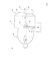
- FIG. 1 diagrammatically illustrates a lighting system consistent with at least one embodiment of the present disclosure.
- FIG. 2 is a partial perspective view illustrating one embodiment of a projector apparatus in a first position consistent with the present disclosure.
- FIG. 3 is a partial perspective view illustrating one embodiment of a projector apparatus in a second position consistent with the present disclosure.
- FIG. 4 is a side cross-sectional view diagrammatically illustrating an embodiment of the projector apparatus of FIG. 2 .
- FIG. 5 is another side cross-sectional view diagrammatically illustrating an embodiment of the projector apparatus of FIG. 2 in a low beam mode.
- FIG. 6 is another side cross-sectional view diagrammatically illustrating an embodiment of the projector apparatus of FIG. 2 in a high beam mode.
- FIG. 7 is another side cross-sectional view diagrammatically illustrating an embodiment of the projector apparatus of FIG. 2 in a daytime running light (DRL) mode.
- DRL daytime running light
- FIG. 8 is a side view of a portion of the shutter shown in FIG. 2 in a first position.
- FIG. 9 is a side view of a portion of the shutter shown in FIG. 2 in a second position.
- FIG. 10 is a side view of a portion of another embodiment of a shutter shown in a first position consistent with the present disclosure.
- FIG. 11 is a side perspective view of another embodiment of a projector apparatus consistent with the present disclosure.
- FIG. 12 is a side perspective view of yet another embodiment of a projector apparatus consistent with the present disclosure.
- FIG. 13 is a flow chart illustrating one embodiment of a method for operating a lighting system consistent with the present disclosure.
- the present disclosure may comprise a lighting system (for example, but not limited to, a lighting system for an automobile or the like) comprising a single projector apparatus having a primary and a secondary light engine in which the primary light engine functions in a first lighting mode (e.g., a low beam and/or high beam mode) and the secondary light engine functions in second mode (e.g., a daytime running light (DRL) mode).
- the single lighting apparatus may therefore integrate two light sources into the lighting apparatus to achieve a DRL mode (as well as low and/or high beam mode) within the same package.
- the lighting system 10 may comprise at least one projector system 12 , a power source 14, and a controller 16.
- the projector system 12 may comprise a housing 18 , a primary light engine 20 , a secondary light engine 22 , and a shutter 24 .
- the housing 18 may be configured to receive at least a portion of the primary light engine 20, the secondary light engine 22 , and/or the shutter 24 .
- the housing 18 may also include one or more lenses 23 , such as reflector and/or projector lens as discussed herein.
- the projector system 12 may receive an electrical input from the power source 14, for example, to energize the primary light engine 20, secondary light engine 22, and/or the shutter 24 .
- the power source 14 may comprise a DC and/or AC power source, and may optionally include one or more inverters, converters, and/or power conditioners.
- one or more ballast circuits 26 may receive an electrical input from the power source 14 and convert it to a stable output for driving the projector system 12 .
- One or more of the ballast circuits 26 may be positioned remotely from the projector system 12 or may be integral with or coupled directed to the housing 18 of the projector system 16 .
- the controller 16 may transmit one or more signals to control the operation of the lighting system 10 .
- the controller 16 may transmit a signal to the power source 14 in order to selectively energize the primary light engine 20 and/or the secondary light engine 22 .
- the controller 16 may also transmit a signal to the shutter 24 to selectively control the position of the shutter 24 as discussed herein.
- the controller 16 may receive an input signal generated under the control of a user and/or generated from one or more sensors such as, but not limited to, an ambient light sensor or the like (not shown) and/or from another computer system (such as, but not limited to, a vehicle electronic control system (ECU)).
- ECU vehicle electronic control system
- the projector apparatus 12 may comprise the primary light engine 20 (not shown for clarity), the secondary light engine 22, at least one reflector 28, at least one projector lens 30, and the shutter 24 which is moveable between at least a first position (as generally illustrated in FIG. 2 ) and a second position (as generally illustrated in FIG. 3 ).
- the reflector 28 may be configured to receive electromagnet radiation generated from the primary light engine 20 .
- the reflector 28 may include a reflector cup 32 including an opening 34 configured to receive at least a portion of the primary light engine 20 , the light emitted therefrom, or one or more electrical leads therefor; an open end 36 from which electromagnet radiation emitted by the primary light engine 20 may be cast from the projector apparatus 12 ; and an interior surface 38 configured to reflect light from the primary light engine 20 toward the open end 36 .
- the phrase "reflector cup” thus includes, but is not limited to known parabolic, elliptical and sphero-elliptical reflector configurations including those with faceted interior surfaces as well as truncated reflector cups.
- truncated reflector cup means a portion of a reflector cup, as may be realized, for example, by dividing a reflector cup along a plane intersecting the longitudinal axis (e.g., intersecting a first end and a second end).
- a truncated reflector cup may thus be configured as one-half of a reflector cup, but may be more or less than half of a reflector cup.
- a truncated reflector cup may have a semi-parabaloid or semi-elipsoid shape.
- the projector lens 30 may be configured to emit electromagnetic radiation, generated from the primary and/or secondary light engines 20, 22, in one or more distribution patterns.
- the projector lens 30 may be configured to distribute electromagnetic radiation in a first distribution pattern in which the electromagnetic radiation is emitted from the projection apparatus 10 substantially at and/or below the horizon.
- the projector lens 30 may also be configured to distribute electromagnetic radiation in a second distribution pattern in which the electromagnetic radiation is emitted from the projection apparatus 10 above and below the horizon.
- the phrase “at and/or below the horizon” means the electromagnetic radiation emitted from the projector lens 30 is emitted generally parallel to ground and/or downwardly from the projector apparatus 10 and towards the ground and the phrase “below the horizon” means the electromagnetic radiation emitted from the projector lens 30 is emitted generally downwardly from the projector apparatus 10 and towards the ground.
- the phrase “above and below the horizon” means the electromagnetic radiation emitted from the projector lens 30 is emitted generally downwardly from the projector apparatus 10 and towards the ground and generally upwardly from the projector apparatus 12 and away from the ground.
- the projector lens 30 may comprise an aspheric or aspherical lens.
- the projector lens 30 may include an upper partial projector lens 40 and a lower partial projector lens 42 .
- the upper and/or lower partial projector lenses 40, 42 may include, but is not limited to, known parabolic, elliptical and sphero-elliptical configurations, conic sections (such as, but not limited to, paraboloids, hyperboloids, and ellipsoids) as well as higher-order aspherics.
- Higher-order aspherics mean surface departures from conic, which are proportional to r 4 , r 6 , r 8 , r 10 , and so on, where r is the radial distance from the optical axis.
- the upper partial projector lens 40 may include a portion of an aspheric lens that having an optical axis O1 with its focus F1 on the upper edge 44 of the shutter 24 .
- the lower partial projector lens 42 may also include a portion of an aspheric lens having an optical axis O2 with its focus F2 either in the center or below the center of the secondary light engine 22 .
- the axis of the lower partial projector lens may be the cut plane C p for both the upper and lower partial projector lenses 40, 42. Both the upper and lower partial projector lenses 40, 42 may have the same focal lengths.
- this is merely one exemplary embodiment of the projector lens 30, and other configurations are within the scope of the present disclosure.
- the specific arrangement, shape and contour of the reflector 28 and the projector 30 will depend on the specific application of the projector apparatus 12 and may include (but is not limited to) such factors as the overall size constraints on the projector apparatus 12 , desired aesthetic appearance of the projector apparatus 12 , as well as the desired electromagnetic radiation output of the projector apparatus 12 .
- the projector apparatus 12 may be useful as an automotive headlight, tail light, and/or signal light, a marine light, an aircraft light, a recreational vehicle light, or other application for which two or more electromagnetic radiation distribution patterns are desired.
- the shutter 24 may be provided to change the distribution pattern.
- the shutter 24 may be configured to move between at least a first position (as generally illustrated in FIG. 2 ) and a second position (as generally illustrated in FIG. 3 ). While the shutter 24 is shown in two positions ( FIGS. 2 and 3 ), it should be appreciated that the shutter 24 may also be configured to be positioned in other orientations (such as, but not limited to, any position intermediate the first and second positions).
- the shutter 24 may include one or more moveable baffle elements 46.
- the baffle element 46 may be coupled to an actuator mechanism 48 as generally illustrated in FIG. 4 .
- the actuator mechanism 48 may include any device for moving the baffle element 46 between the first and second positions.
- the actuator mechanism 48 may comprise a solenoid and/or motor coupled to baffle element 46 through associated gearing, levers, cams, linkages, pivot arms, or the like, for pivoting the baffle 46 .
- the actuator mechanism 48 may move the baffle element 46 upon receipt of a signal from the controller 16 ( FIG. 1 ) as discussed herein. Alternatively, a user may directly urge the actuator mechanism 48 to move the baffle element 46 .
- a projector apparatus 12 consistent with the present disclosure comprises a primary light engine 20 including any known light source configuration such as one or more incandescent light source (such as, but not limited to, a halogen lamp), LEDs (with or without a remote phosphor element), a gas discharge light source such as a fluorescent tube (e.g., in a compact fluorescent (CFL) lamp), and/or a high-intensity discharge (HID) light source.
- the primary light engine 20 is illustrated as a single light source, the primary light engine 20 may include multiple light sources depending on the application.
- the phrase "primary light engine” is intended to mean a light source which provides the primary or main source of illumination.
- secondary light engine as used herein is intended to mean a light source which primarily functions to increase the visibility of an object (such as, but not limited to, automobiles, aircraft, marine vessels, as well as other vehicles) to others, particularly during daylight.
- the secondary light engine 22 may comprise one or more any known light source configuration including, but not limited to, at least one discharge light source such as a fluorescent tube (e.g., in a CFL lamp), incandescent light source (such as, but not limited to, a halogen lamp), a HID light source and/or LEDs (with or without a remote phosphor element).
- the secondary light engine 22 may be configured to function as a daytime running light (DRL).
- a DRL includes a light emitted from the projector apparatus 12 which increases the visibility/conspicuity of an object (such as, but not limited to, a vehicle) during daylight conditions.
- the DRL emits electromagnetic radiation which is dimmer than the electromagnetic radiation emitted during operation of a low beam headlight.
- the DRL emits electromagnetic radiation both above and below the horizon.
- the electromagnetic radiation may include, but is not limited to, a white, yellow, amber light.
- the secondary light engine 22 may be configured to be disposed within the projector apparatus 12 such that the secondary light engine 22 is between the baffle element 46 and the projector lens 30 and also such that the baffle element 46 is disposed between the secondary light engine 22 and the reflector 28 .
- the secondary light engine 22 may be energized upon receipt of a signal from the controller 16 ( FIG. 1 ). For example, the secondary light engine 22 may be automatically switched on by the controller 16 when a vehicle is turned on and/or moving forward during daylight conditions.
- the use of separate primary and secondary light engines 20, 22 allows each light engine 20, 22 to operate at a higher efficiency.
- HID lamps generally cannot be dimmed below their designed steady-state operating voltages (power), and while halogens can be dimmed, they generally do not operate well at voltages (power) well below the designed steady state operating power.
- the use of a separate and distinct secondary light engine 22 thus allows the projector apparatus 12 to effectively provide a low beam mode (and optionally high beam mode) as well as a DRL mode.
- the controller 16 may transmit one or more signals configured to energize the primary light engine 20 (e.g., but not limited to, a HID lamp) and emit electromagnetic radiation (e.g., illustrated schematically as light beams B1 and B2 ).
- the controller 16 may transmit a signal to the power source 14 (also shown in FIG. 1 ) , which may in turn provide the necessary electrical input to the primary light engine 20 .
- the controller 16 may also transmit one or more signals to the shutter 24 to arrange the shutter in a first position.
- first position is intended to mean that at least a portion of the shutter 24 (e.g., the baffle element 46 ) obscures a portion of the projector lens 30 from the light beams B1, B2 emitted from the primary light engine 20 .
- the shutter 24 may be configured to obscure the projector lens 30 from the light beams B1, B2 emitted from the primary light engine 20 when in the first position such that the electromagnetic radiation emitted projector apparatus 12 is distributed at and/or below the horizon.
- the shutter 24 may be configured to obscure at least a portion 50 of the upper partial projector lens 40 from the primary light source 20 when arranged in the first position.
- the reflector 28 may also be configured to ensure that the light beams B1, B2 emitted from the primary light engine 20 , and reflected therefrom, are obscured from the portion 50 of the projector lens 30 when the shutter 24 is in the first position.
- the primary light engine facing surface 52 of the shutter 24 may optionally be reflective to enhance the output from the primary light engine 20 when the shutter 24 is in the first position.
- the controller 16 may transmit one or more signals configured to energize the primary light engine 20 and emit electromagnetic radiation (e.g., illustrated schematically as light beams B3 and B4 ).
- the controller 16 may transmit a signal to the power source 14 (also shown in FIG. 1 ), which may in turn provide the necessary electrical input to the primary light engine 20 .
- the controller 16 may also transmit one or more signals to the shutter 24 to arrange the shutter in a second position.
- the phrase "second position" is intended to mean that the electromagnetic radiation (e.g., B3, B4) emitted from the primary light engine 20 may exit the projector lens 30 generally unobstructed.
- the electromagnetic radiation (e.g., B3, B4) emitted from the primary light engine 20 may exit both the upper and lower partial portions 40, 42 of the projector lens 30 when the shutter 24 is in the second position such that the electromagnetic radiation emitted projector apparatus 12 is distributed at and/or below the horizon.
- the shutter 24 e.g., the baffle element 46
- the shutter 24 generally does not obscures any portion of the projector lens 30 from the light beams B3, B4 emitted from the primary light engine 20 .
- the controller 16 may transmit one or more signals configured to energize the secondary light engine 22 and emit electromagnetic radiation (e.g., illustrated schematically as light beams B5 and B6 ).
- the controller 16 may transmit a signal to the power source 14 (also shown in FIG. 1 ), which may in turn provide the necessary electrical input to the secondary light engine 22 .
- the controller 16 may also transmit one or more signals to the shutter 24 to arrange the shutter in the first position.
- the shutter 24 may be configured to emit at least a portion of the electromagnetic radiation (e.g., B5, B6 ), generated by the secondary light engine 22 , through the projector lens 30 .
- the shutter 24 may be configured to emit at least a portion of the electromagnetic radiation B5, B6, generated by the secondary light engine 22 , through the upper and lower partial portions 40, 42 of the projector lens 30 such that the electromagnetic radiation B5, B6 is emitted above and below the horizon.
- the secondary light engine 22 may be coupled to the baffle element 46 such that the secondary light engine 22 moves with the baffle element 46 as the shutter 24 moves between the first and second positions.
- the secondary light engine 22 may comprise one or more LEDs 56a-n (with or without a remote phosphor element) coupled to one or more base plates 58 , which may be configured as printed circuit boards (PCBs) including electronics and/or conductive traces and electrical leads thereon receiving an electrical input and energizing the LEDs 56a-n.
- the LEDs 56a-n may include a series of chips on a ceramic submount or discrete LED packages, such as, but not limited to, white Dragon LEDs, which are available from the assignees of the present disclosure.
- the base plates 58 may be thermally conductive and may be thermally coupled to the baffle element 46, which may be constructed from a material having a high thermal conductance such as, but not limited to, metal, ceramic, and alloys.
- the baffle element 46 of the shutter 24 may function as a heat sink for the secondary light engine 22 . While it is possible to operate both the primary and secondary light engines 20, 22 simultaneously, it may be necessary to it may be beneficial to operate them serially (i.e., only one light engine at a time), particularly when the secondary light engine 22 is functioning as a DRL.
- operating the primary and secondary light engines 20, 22 serially may allow the baffle element 46 to more efficiently function as a heat sink for the secondary light engine 22 generally without consideration of the extra heat load generated by the primary light engine 20 .
- the term “coupled” as used herein refers to any connection, coupling, link, or the like and does not require a direct physical or electrical connection.
- thermally coupled refers to such a connection, coupling, link, or the like that allows heat to be transferred from one element to the other thermally coupled element.
- the secondary light engine 22 may include a dispersion lens 60 .
- the dispersion lens 60 may be configured to emit a larger electromagnetic radiation distribution pattern, which may be needed to achieve the desired wide spread for the DRL mode.
- the larger electromagnetic radiation distribution pattern may ensure that a sufficient amount of electromagnetic radiation enters both the upper and lower partial projector lenses 40, 42 in order to achieve the desired amount of electromagnetic radiation above and below the horizon.
- the secondary light source 22 may include a collimating lens rather than a dispersion lens 60 , depending on the type of light source used for the secondary light engine 22.
- either a dispersion lens 60 or a collimating lens may be used to either spread or narrow the light emitted by the secondary light engine 22 in order to optimize illumination and collection efficiency of light captured by the projector lens 30.
- the lower partial projector lens 42 may be displaced vertically in order to achieve an even distribution above and below the horizon during DRL mode.
- the lower partial projector lens 42 may be displaced a few mm (such as, but not limited to, 4 mm). While displacing the lower partial projector lens 42 relative to the upper partial projector lens 40 may vertically stretch emission patterns of the low and high beam modes, the shutter 24 will still produce a sharp cut-off between around the horizon. Any reduction of the hot spot of the low and/or high beam modes may be compensated by the reflector 28 or by a larger projector lens 30 .
- the shutter 24 may be configured to move about a pivot axis A.
- Power may be provide to the secondary light engine 22 through wires or flex board 62.
- the wires 62 may electrically couple the PCB 58 to a connector 64 mounted on a second PCB 66 .
- the wires 62 may be configured to be flexible enough to resiliently bend around the pivot axis A of the shutter 24 , and may optionally include a loop 68 , best seen in FIG. 9 .
- the loop 68 may be configured to avoid kinks and wear and minimize stress on the wire or flex board 62 .
- one or more retainers 70a-n may be provided along the baffle element 46 to retain the wire or flex board 62 .
- wire or flex board 62 has been shown on/about an exterior surface of the baffle element 46 , it may be appreciated that that the wire or flex board 62 may also be at least partially disposed within the baffle element 46 , for example, within a lumen defined by the baffle element 46 .
- secondary light engine 22a may be moveably coupled to the baffle element 46 and may be used with the projector 30 described herein.
- the secondary light engine 22a may move from a first position (generally illustrated in dotted lines) to a second position (generally illustrated in solid lines). In the first position, the secondary light engine 22a is below the upper edge 44 of the baffle element 46 .
- the secondary light engine 22a may be arranged in the first position whenever the secondary light engine 22a is not energized. By arranging the secondary light engine 22a below the upper edge 44 of the baffle element 46 , the secondary light engine 22a will not interfere with or block radiation emitted from the primary light engine 20 .
- the secondary light engine 22a may be arranged in the second position whenever the secondary light engine 22a is energized (e.g., during DRL mode). By moving the secondary light engine 22a upwardly in the direction of the arrow towards and/or beyond the upper edge 44 of the baffle element 46 , the secondary light engine 22a may be aligned with the One benefit of moveably coupling the secondary light engine 22a onto the baffle element 46 is that may allow the secondary light engine 22a to be aligned with both the first and second optical axis O1, O2 as well their focal points F1, F2, of the upper and lower partial projection lenses 40 , 42 (see FIG. 4 ), thereby ensuring a generally even distribution above and below the horizon.
- the projector apparatus 12a may comprise a housing 18a , a primary light engine 20 , a secondary light engine 22a , at least one reflector 28 , at least one projector lens 30, and a shutter 24b which is moveable between at least a first position and a second position as generally described herein.
- the shutter 24b may also be configured to emit at least a portion of the electromagnetic radiation generated by the secondary light engine 22a through the projector lens 30.
- the shutter 24b may be configured to emit at least a portion of the electromagnetic radiation generated by the secondary light engine 22a through the upper and lower partial portions 40 , 42 of the projector lens 30 such that the electromagnetic radiation is emitted above and below the horizon when the projector apparatus 12a is in the DRL mode.
- the projector apparatus 12a may therefore function in a low beam mode (and optionally a high beam mode) as well as a DRL mode as discussed herein.
- the secondary light engine 22a may be configured to be disposed within the projector apparatus 12a such that the secondary light engine 22a is between the baffle element 46a and the projector lens 30 and also such that the baffle element 46a is disposed between the secondary light engine 22a and the reflector 28 . More specifically, the housing 18a may include an opening 66 configured to receive at least a portion of the secondary light engine 22a , the light (generally illustrated as light beams B7 and B8 ) emitted therefrom, or one or more electrical leads therefore. The secondary light engine 22a may therefore emit electromagnet radiation B7, B8 which may be reflected by a mirror 72 located on the shutter 24b .
- the mirror 72 may redirect the electromagnet radiation B7 , B8 generated by the secondary light engine 22a and emit the electromagnet radiation B7 , B8 through the projector lens 30 .
- the mirror 72 may include a collimating optic (e.g., a parabolic mirror or focusing lens) configured to distribute or spread the electromagnet radiation B7 , B8 (if necessary) through the upper and lower partial projector lenses 40 , 42 of the projector lens 30 in order to provide a DRL mode.
- a collimating optic e.g., a parabolic mirror or focusing lens
- the mirror 72 may be moveably coupled to the baffle element 46a .
- the mirror 72 may be configured to pivot between an extended position during DRL mode (as shown in solid lines) and a retracted position (as shown in dotted lines) during low beam and/or high beam mode.
- the mirror 72 may also be stationary with respect to the baffle element 46a , and the angle of the secondary light engine 22a may be adjusted relative to the mirror 72 in order to ensure the desired light distribution through the projector lens 30 .
- the secondary light engine 22a may include any known light source configuration such as one or more incandescent light source (such as, but not limited to, a halogen lamp), LEDs (with or without a remote phosphor element), a gas discharge light source such as a fluorescent tube (e.g., in a CFL lamp), and/or a HID light source. While the secondary light engine 22a is illustrated as a single light source, the secondary light engine 22a may include multiple light sources depending on the application.
- incandescent light source such as, but not limited to, a halogen lamp
- LEDs with or without a remote phosphor element
- a gas discharge light source such as a fluorescent tube (e.g., in a CFL lamp)
- HID light source e.g., a CFL lamp
- the secondary light engine 22a is illustrated as a single light source, the secondary light engine 22a may include multiple light sources depending on the application.
- the projector apparatus 12b may be similar to the projector apparatus 12a of FIG. 11 except that the position of the secondary light engine 22b may be altered.
- the secondary light engine 22b may be arranged above the shutter 24c rather than below as illustrated in FIG. 11 .
- the mirror 72a may function similarly, i.e., the mirror 72a may redirect the electromagnet radiation (e.g., light beams B9, B10) generated by the secondary light engine 22b and emit the light beams B11, B12 through the projector lens 30 .
- the arrangement of FIG. 12 has the advantage that the heat from the secondary light engine 22b can rise from the heat sink, which may help further cool the secondary light engine 22b .
- the secondary light engine 22b is an incandescent light source (such as, but not limited to, a halogen lamp), a gas discharge light source such as a fluorescent tube (e.g., in a CFL lamp), and/or a HID light source, though it may also be beneficial for LED light sources as well.
- an incandescent light source such as, but not limited to, a halogen lamp
- a gas discharge light source such as a fluorescent tube (e.g., in a CFL lamp)
- HID light source e.g., a CFL lamp
- FIG. 13 one embodiment of a method 1300 of operating a lighting system 10 consistent with the present disclosure is generally illustrated.
- one or more modes of operation may be selected, acts 1310, 1312, 1314.
- any one of the modes of operation may be selected in any order.
- the upper partial projector lens 40 of the projector lens 30 may be designed to create the low and high beam
- the lower partial projector lens 42 of the projector lens 30 may create the DRL beam.
- both the upper and lower partial projector lenses 40, 42 may contribute (at least to some extent) to all the beams as described herein.
- a low beam mode may be selected, act 1310.
- the shutter 24 may be positioned in a first position wherein the shutter 24 at least partially obscures a portion of the projector lens 30 (e.g., the lower partial projector lens 42 ) from the primary light engine 20, act 1316.
- the default position of the shutter 24 may be the first position, in which case the position of the shutter 24 may simply be verified.
- the primary light engine 20 may be energized to emit electromagnetic radiation, act 1318. The electromagnetic radiation emitted from the primary light engine 20 may be reflected by the reflector 28, and ultimately emitted from the projector lens 30 primarily at and/or below the horizon, act 1320.
- the upper partial projector lens 40 of the projector lens 30 may create the low beam pattern.
- the lower partial projector lens 42 may be substantially obscured from the primary light engine 20; however, the lower partial projector lens 42 may add some foreground light to the lower part of the beam.
- the shutter 24 may be positioned in a second position wherein the projector lens 30 (e.g., the upper and lower partial projector lenses 40, 42) are exposed to the primary light engine 20, act 1322.
- the default position of the shutter 24 may be the second position, in which case the position of the shutter 24 may simply be verified.
- the primary light engine 20 may be energized to emit electromagnetic radiation, act 1324. The electromagnetic radiation emitted from the primary light engine 20 may be reflected by the reflector 28, and ultimately emitted from the projector lens 30 primarily above and below the horizon, act 1326.
- the upper partial projector lens 40 of the projector lens 30 may create the high beam pattern and the lower partial projector lens 42 may add some foreground light to the lower part of the beam.
- the shutter 24 may be positioned in the second position, act 1328.
- the secondary light engine 22 may be energized to emit electromagnetic radiation, act 1330.
- the electromagnetic radiation emitted from the secondary light engine 22 may be emitted from the projector lens 30 primarily above and below the horizon, act 1332.
- the lower partial projector lens 42 of the projector lens 30 may create the DRL beam pattern, but mostly the center and lower portion of the beam; however, it does create some of the upper part as well.
- the upper partial projector lens 40 of the projector lens 30 may add light to the upper portion of the beam.
- either or both of the light engines may include multiple light sources depending on the application.
- either of both of the light engines may include any known light source configuration such as one or more incandescent light source (such as, but not limited to, a halogen lamp), LEDs (with or without a remote phosphor element), a gas discharge light source such as a fluorescent tube (e.g., in a CFL lamp), a HID light source, or any combination thereof.
- one or more of the light engines may emit light in the visible spectrum (herein defined as electromagnetic radiation whose wavelength lies within the spectra of 380-700 nm) as well as (or alternatively) invisible UV or IR light (herein defined as electromagnetic radiation whose wavelength lies within the spectra of 320-380 nm for UV and about 700-1600 nm for IR).
- electromagnetic radiation whose wavelength lies within the spectra of 380-700 nm
- invisible UV or IR light herein defined as electromagnetic radiation whose wavelength lies within the spectra of 320-380 nm for UV and about 700-1600 nm for IR.
- the present disclosure may feature a projection apparatus (12, 12a-b) comprising a reflector (28) configured to reflect electromagnetic radiation emitted from a primary light engine (20) , a projector lens (30) configured to project at least a portion of the reflected electromagnetic radiation from the reflector (28) , and a shutter (24 , 24a-c) disposed between a secondary light engine (22, 22a-b) and the reflector (28) .
- the shutter (24 , 24a-c) may be configured to selectively obscure a portion of the projector lens (30) from the reflected electromagnetic radiation.
- the shutter (24 , 24a-c) may be further configured to selectively emit at least a portion of electromagnetic radiation from the secondary light engine (22 , 22a-b) through at least a portion of the projector lens (30) .
- a lighting system (10) may comprise a primary light engine (20) ; a secondary light engine (22 , 22a-b) ; a projector lens (30) , a reflector (28) , and shutter (24 , 24a-c) .
- the projector lens (30) may comprise an upper partial projector lens (40) and a lower partial projector lens (42) .
- the upper partial projector lens (40) may be configured to project electromagnetic radiation generally below a horizon and the lower partial projector lens (42) may be configured to project electromagnetic radiation generally above the horizon.
- the reflector (28) may be configured to reflect electromagnetic radiation emitted from the primary light engine (20) .
- the shutter (24 , 24a-c) may be disposed between the secondary light engine (22 , 22a-b) and the reflector (28) and may be configured to move between a first and at least a second position. In the first position, the shutter (24 , 24a-c) may be configured to obscure the lower partial projector lens (42) from the reflected electromagnetic radiation. The shutter (24 , 24a-c) may also be further configured to selectively emit at least a portion of electromagnetic radiation from the secondary light engine (22 , 22a-b) through the upper partial projector lens (42) and the lower partial projector lens (42) . In the second position, the shutter (24 , 24a-c) may be configured to allow the reflected electromagnetic radiation from the primary light engine (20) to be emitted from the upper partial projector lens (40) and the lower partial projector lens (42) .
- a method (1300) of operating a lighting system (10) may comprise selecting (1314) a daytime running light (DRL) mode.
- a shutter (24 , 24a-c) may be positioned (1328) in a first position at least partially obscuring a lower partial projector lens (42) of a projector lens (30) from a primary light engine (20) and a secondary light engine (22, 22a-b) may be energized (1330) .
- the secondary light engine (22 , 22a-b) may be disposed between the shutter (24 , 24a-c) and the projector lens (30) . Radiation generated from the secondary light engine (22, 22a-c) may then be emitted (1332) through an upper partial projector lens (40) and the lower partial projector lens (42) such that the radiation is emitted generally above and generally below a horizon.
Abstract
Description
- N/A
- The present application relates to lighting systems and more particularly to lighting systems including daytime running lights.
- Lighting systems (such as headlights) are well-known and are used in a wide variety of applications, including automotive applications. In general, a lighting system includes one or more projector apparatus for emitting light distinct patterns. For example, a lighting system may emit light in a low-beam mode in which light is generally emitted below the horizon. The lighting system may also emit light in a high beam mode in which light is generally emitted above and below the horizon. Recently, lighting systems have also begun to emit light in a daytime running lights (DRL) mode in order to increase the visibility of the vehicle during daylight conditions. In a DRL mode, light is emitted above and below the horizon, however, the light is typically emitted at a lower overall output compared to either the low and/or high beam modes (for example, in order to comply with SAE regulations or ECE specifications). Examples of such lighting system may be found in
U.S. Patent No. 7,316,492 (Yamamura ),U.S. Patent Pub. No. 2009/0097269 (Stauss );U.S. Patent Pub. No. 2004/0240221 (Choi );U.S. Patent Pub. No. 2006/0002128 (Suzuki );U.S. Patent Pub. No. 2004/0228137 (Mensales );U.S. Patent Pub. No. 2008/0037269 (Sugiyama );U.S. Patent Pub. No. 2005/0073853 (Stam );U.S. Patent Pub. No. 2008/0037270 (Kagiyama );U.S. Patent No. 6,467,940 (Eschler ); andU.S. Patent No. 6,976,772 (Albou ). - In many applications, it may be desirable for the low and/or high beam mode to utilize a halogen lamp or a high-intensity discharge (HID) light source. Unfortunately, it is generally not possible to operate HID light sources at reduced voltages (power) compared to their designed, steady-state operating voltages. Similarly, while it may be possible to operate halogens at reduced power levels, halogens are typically not very efficient below their designed, steady-state operating powers, particularly ECE specifications due to the high dimming ratio necessary. One approach to address these issues has been to provide a separate, dedicated lighting apparatus designed to function only in the DRL mode. Unfortunately, such an approach increases the costs since two lighting apparatus must be provided for each side of the vehicle. In addition, operating a single lighting source in both DRL mode as well as low/high beam mode may significantly shorten the lifespan of the lighting source since the light source would be operating continuously while the vehicle is running.
- Reference should be made to the following detailed description which should be read in conjunction with the following figures, wherein like numerals represent like parts:
-
FIG. 1 diagrammatically illustrates a lighting system consistent with at least one embodiment of the present disclosure. -
FIG. 2 is a partial perspective view illustrating one embodiment of a projector apparatus in a first position consistent with the present disclosure. -
FIG. 3 is a partial perspective view illustrating one embodiment of a projector apparatus in a second position consistent with the present disclosure. -
FIG. 4 is a side cross-sectional view diagrammatically illustrating an embodiment of the projector apparatus ofFIG. 2 . -
FIG. 5 is another side cross-sectional view diagrammatically illustrating an embodiment of the projector apparatus ofFIG. 2 in a low beam mode. -
FIG. 6 is another side cross-sectional view diagrammatically illustrating an embodiment of the projector apparatus ofFIG. 2 in a high beam mode. -
FIG. 7 is another side cross-sectional view diagrammatically illustrating an embodiment of the projector apparatus ofFIG. 2 in a daytime running light (DRL) mode. -
FIG. 8 is a side view of a portion of the shutter shown inFIG. 2 in a first position. -
FIG. 9 is a side view of a portion of the shutter shown inFIG. 2 in a second position. -
FIG. 10 is a side view of a portion of another embodiment of a shutter shown in a first position consistent with the present disclosure. -
FIG. 11 is a side perspective view of another embodiment of a projector apparatus consistent with the present disclosure. -
FIG. 12 is a side perspective view of yet another embodiment of a projector apparatus consistent with the present disclosure. -
FIG. 13 is a flow chart illustrating one embodiment of a method for operating a lighting system consistent with the present disclosure. - In general, the present disclosure may comprise a lighting system (for example, but not limited to, a lighting system for an automobile or the like) comprising a single projector apparatus having a primary and a secondary light engine in which the primary light engine functions in a first lighting mode (e.g., a low beam and/or high beam mode) and the secondary light engine functions in second mode (e.g., a daytime running light (DRL) mode). The single lighting apparatus may therefore integrate two light sources into the lighting apparatus to achieve a DRL mode (as well as low and/or high beam mode) within the same package.
- Turning now to
FIG. 1 , one embodiment of alighting system 10 consistent with the present disclosure is generally illustrated. Thelighting system 10 may comprise at least oneprojector system 12, apower source 14, and acontroller 16. Theprojector system 12 may comprise ahousing 18, aprimary light engine 20, asecondary light engine 22, and ashutter 24. Thehousing 18 may be configured to receive at least a portion of theprimary light engine 20, thesecondary light engine 22, and/or theshutter 24. Thehousing 18 may also include one ormore lenses 23, such as reflector and/or projector lens as discussed herein. - The
projector system 12 may receive an electrical input from thepower source 14, for example, to energize theprimary light engine 20,secondary light engine 22, and/or theshutter 24. Thepower source 14 may comprise a DC and/or AC power source, and may optionally include one or more inverters, converters, and/or power conditioners. Optionally, one ormore ballast circuits 26 may receive an electrical input from thepower source 14 and convert it to a stable output for driving theprojector system 12. One or more of theballast circuits 26 may be positioned remotely from theprojector system 12 or may be integral with or coupled directed to thehousing 18 of theprojector system 16. - The
controller 16 may transmit one or more signals to control the operation of thelighting system 10. For example, thecontroller 16 may transmit a signal to thepower source 14 in order to selectively energize theprimary light engine 20 and/or thesecondary light engine 22. Thecontroller 16 may also transmit a signal to theshutter 24 to selectively control the position of theshutter 24 as discussed herein. Thecontroller 16 may receive an input signal generated under the control of a user and/or generated from one or more sensors such as, but not limited to, an ambient light sensor or the like (not shown) and/or from another computer system (such as, but not limited to, a vehicle electronic control system (ECU)). - Turning now to
FIGS. 2 and3 , an exploded view of one embodiment of theprojector apparatus 12 is generally illustrated (thehousing 18 is not shown for clarity). As can be seen, theprojector apparatus 12 may comprise the primary light engine 20 (not shown for clarity), thesecondary light engine 22, at least onereflector 28, at least oneprojector lens 30, and theshutter 24 which is moveable between at least a first position (as generally illustrated inFIG. 2 ) and a second position (as generally illustrated inFIG. 3 ). - The
reflector 28 may be configured to receive electromagnet radiation generated from theprimary light engine 20. For example, thereflector 28 may include areflector cup 32 including anopening 34 configured to receive at least a portion of theprimary light engine 20, the light emitted therefrom, or one or more electrical leads therefor; anopen end 36 from which electromagnet radiation emitted by theprimary light engine 20 may be cast from theprojector apparatus 12; and aninterior surface 38 configured to reflect light from theprimary light engine 20 toward theopen end 36. The phrase "reflector cup" thus includes, but is not limited to known parabolic, elliptical and sphero-elliptical reflector configurations including those with faceted interior surfaces as well as truncated reflector cups. The phrase "truncated reflector cup" means a portion of a reflector cup, as may be realized, for example, by dividing a reflector cup along a plane intersecting the longitudinal axis (e.g., intersecting a first end and a second end). A truncated reflector cup may thus be configured as one-half of a reflector cup, but may be more or less than half of a reflector cup. For example, a truncated reflector cup may have a semi-parabaloid or semi-elipsoid shape. - The
projector lens 30 may be configured to emit electromagnetic radiation, generated from the primary and/orsecondary light engines projector lens 30 may be configured to distribute electromagnetic radiation in a first distribution pattern in which the electromagnetic radiation is emitted from theprojection apparatus 10 substantially at and/or below the horizon. Theprojector lens 30 may also be configured to distribute electromagnetic radiation in a second distribution pattern in which the electromagnetic radiation is emitted from theprojection apparatus 10 above and below the horizon. As used herein, the phrase "at and/or below the horizon" means the electromagnetic radiation emitted from theprojector lens 30 is emitted generally parallel to ground and/or downwardly from theprojector apparatus 10 and towards the ground and the phrase "below the horizon" means the electromagnetic radiation emitted from theprojector lens 30 is emitted generally downwardly from theprojector apparatus 10 and towards the ground. In addition, as used herein, the phrase "above and below the horizon" means the electromagnetic radiation emitted from theprojector lens 30 is emitted generally downwardly from theprojector apparatus 10 and towards the ground and generally upwardly from theprojector apparatus 12 and away from the ground. - For example, the
projector lens 30 may comprise an aspheric or aspherical lens. According to one embodiment, theprojector lens 30 may include an upperpartial projector lens 40 and a lowerpartial projector lens 42. The upper and/or lowerpartial projector lenses - Referring now to
FIG. 4 , a cross-sectional view of one embodiment illustrating theprojector lens 30 is shown. In particular, the upperpartial projector lens 40 may include a portion of an aspheric lens that having an optical axis O1 with its focus F1 on theupper edge 44 of theshutter 24. The lowerpartial projector lens 42 may also include a portion of an aspheric lens having an optical axis O2 with its focus F2 either in the center or below the center of thesecondary light engine 22. The axis of the lower partial projector lens may be the cut plane Cp for both the upper and lowerpartial projector lenses partial projector lenses projector lens 30, and other configurations are within the scope of the present disclosure. - The specific arrangement, shape and contour of the
reflector 28 and theprojector 30 will depend on the specific application of theprojector apparatus 12 and may include (but is not limited to) such factors as the overall size constraints on theprojector apparatus 12, desired aesthetic appearance of theprojector apparatus 12, as well as the desired electromagnetic radiation output of theprojector apparatus 12. Theprojector apparatus 12 may be useful as an automotive headlight, tail light, and/or signal light, a marine light, an aircraft light, a recreational vehicle light, or other application for which two or more electromagnetic radiation distribution patterns are desired. - The
shutter 24 may be provided to change the distribution pattern. In particular, theshutter 24 may be configured to move between at least a first position (as generally illustrated inFIG. 2 ) and a second position (as generally illustrated inFIG. 3 ). While theshutter 24 is shown in two positions (FIGS. 2 and3 ), it should be appreciated that theshutter 24 may also be configured to be positioned in other orientations (such as, but not limited to, any position intermediate the first and second positions). - For example, the
shutter 24 may include one or moremoveable baffle elements 46. For the sake clarity, only asingle baffle element 46 is shown; however, more than onebaffle element 46 may be provided depending on the application. Thebaffle element 46 may be coupled to anactuator mechanism 48 as generally illustrated inFIG. 4 . Theactuator mechanism 48 may include any device for moving thebaffle element 46 between the first and second positions. For example, theactuator mechanism 48 may comprise a solenoid and/or motor coupled to baffleelement 46 through associated gearing, levers, cams, linkages, pivot arms, or the like, for pivoting thebaffle 46. Theactuator mechanism 48 may move thebaffle element 46 upon receipt of a signal from the controller 16 (FIG. 1 ) as discussed herein. Alternatively, a user may directly urge theactuator mechanism 48 to move thebaffle element 46. - Referring now to
FIG. 5 , aprojector apparatus 12 consistent with the present disclosure comprises aprimary light engine 20 including any known light source configuration such as one or more incandescent light source (such as, but not limited to, a halogen lamp), LEDs (with or without a remote phosphor element), a gas discharge light source such as a fluorescent tube (e.g., in a compact fluorescent (CFL) lamp), and/or a high-intensity discharge (HID) light source. While theprimary light engine 20 is illustrated as a single light source, theprimary light engine 20 may include multiple light sources depending on the application. As used herein, the phrase "primary light engine" is intended to mean a light source which provides the primary or main source of illumination. In contrast, the term "secondary light engine" as used herein is intended to mean a light source which primarily functions to increase the visibility of an object (such as, but not limited to, automobiles, aircraft, marine vessels, as well as other vehicles) to others, particularly during daylight. - According to one embodiment consistent with the present disclosure, the
secondary light engine 22 may comprise one or more any known light source configuration including, but not limited to, at least one discharge light source such as a fluorescent tube (e.g., in a CFL lamp), incandescent light source (such as, but not limited to, a halogen lamp), a HID light source and/or LEDs (with or without a remote phosphor element). According to one embodiment, thesecondary light engine 22 may be configured to function as a daytime running light (DRL). As used herein, a DRL includes a light emitted from theprojector apparatus 12 which increases the visibility/conspicuity of an object (such as, but not limited to, a vehicle) during daylight conditions. The DRL emits electromagnetic radiation which is dimmer than the electromagnetic radiation emitted during operation of a low beam headlight. In addition, the DRL emits electromagnetic radiation both above and below the horizon. The electromagnetic radiation may include, but is not limited to, a white, yellow, amber light. - The
secondary light engine 22 may be configured to be disposed within theprojector apparatus 12 such that thesecondary light engine 22 is between thebaffle element 46 and theprojector lens 30 and also such that thebaffle element 46 is disposed between thesecondary light engine 22 and thereflector 28. Thesecondary light engine 22 may be energized upon receipt of a signal from the controller 16 (FIG. 1 ). For example, thesecondary light engine 22 may be automatically switched on by thecontroller 16 when a vehicle is turned on and/or moving forward during daylight conditions. The use of separate primary andsecondary light engines light engine secondary light engine 22 thus allows theprojector apparatus 12 to effectively provide a low beam mode (and optionally high beam mode) as well as a DRL mode. - Turning now to
FIG. 5 , one embodiment of theprojector apparatus 12 is illustrated in the low (e.g., regular) beam mode. In particular, the controller 16 (FIG. 1 ) may transmit one or more signals configured to energize the primary light engine 20 (e.g., but not limited to, a HID lamp) and emit electromagnetic radiation (e.g., illustrated schematically as light beams B1 and B2). For example, thecontroller 16 may transmit a signal to the power source 14 (also shown inFIG. 1 ), which may in turn provide the necessary electrical input to theprimary light engine 20. Thecontroller 16 may also transmit one or more signals to theshutter 24 to arrange the shutter in a first position. As used herein, the phrase "first position" is intended to mean that at least a portion of the shutter 24 (e.g., the baffle element 46) obscures a portion of theprojector lens 30 from the light beams B1, B2 emitted from theprimary light engine 20. - For example, when the
shutter 24 may be configured to obscure theprojector lens 30 from the light beams B1, B2 emitted from theprimary light engine 20 when in the first position such that the electromagnetic radiation emittedprojector apparatus 12 is distributed at and/or below the horizon. According to one embodiment consistent with the present disclosure, theshutter 24 may be configured to obscure at least aportion 50 of the upperpartial projector lens 40 from theprimary light source 20 when arranged in the first position. Optionally, thereflector 28 may also be configured to ensure that the light beams B1, B2 emitted from theprimary light engine 20, and reflected therefrom, are obscured from theportion 50 of theprojector lens 30 when theshutter 24 is in the first position. Additionally, the primary lightengine facing surface 52 of theshutter 24 may optionally be reflective to enhance the output from theprimary light engine 20 when theshutter 24 is in the first position. - Turning now to
FIG. 6 , theprojector apparatus 12 ofFIG. 5 is illustrated in an optional high beam mode. In particular, the controller 16 (FIG. 1 ) may transmit one or more signals configured to energize theprimary light engine 20 and emit electromagnetic radiation (e.g., illustrated schematically as light beams B3 and B4). For example, thecontroller 16 may transmit a signal to the power source 14 (also shown inFIG. 1 ), which may in turn provide the necessary electrical input to theprimary light engine 20. Thecontroller 16 may also transmit one or more signals to theshutter 24 to arrange the shutter in a second position. As used herein, the phrase "second position" is intended to mean that the electromagnetic radiation (e.g., B3, B4) emitted from theprimary light engine 20 may exit theprojector lens 30 generally unobstructed. For example, the electromagnetic radiation (e.g., B3, B4) emitted from theprimary light engine 20 may exit both the upper and lowerpartial portions projector lens 30 when theshutter 24 is in the second position such that the electromagnetic radiation emittedprojector apparatus 12 is distributed at and/or below the horizon. Thus, the shutter 24 (e.g., the baffle element 46) generally does not obscures any portion of theprojector lens 30 from the light beams B3, B4 emitted from theprimary light engine 20. - Referring now to
FIG. 7 , theprojector apparatus 12 ofFIG. 5 is illustrated in a DRL mode. In particular, the controller 16 (FIG. 1 ) may transmit one or more signals configured to energize thesecondary light engine 22 and emit electromagnetic radiation (e.g., illustrated schematically as light beams B5 and B6). For example, thecontroller 16 may transmit a signal to the power source 14 (also shown inFIG. 1 ), which may in turn provide the necessary electrical input to thesecondary light engine 22. Thecontroller 16 may also transmit one or more signals to theshutter 24 to arrange the shutter in the first position. Theshutter 24 may be configured to emit at least a portion of the electromagnetic radiation (e.g., B5, B6), generated by thesecondary light engine 22, through theprojector lens 30. For example, theshutter 24 may be configured to emit at least a portion of the electromagnetic radiation B5, B6, generated by thesecondary light engine 22, through the upper and lowerpartial portions projector lens 30 such that the electromagnetic radiation B5, B6 is emitted above and below the horizon. - According to one embodiment, the
secondary light engine 22 may be coupled to thebaffle element 46 such that thesecondary light engine 22 moves with thebaffle element 46 as theshutter 24 moves between the first and second positions. Referring now toFIGS. 8 and 9 , a close-up of theshutter 24 is shown in the first position (FIG. 8 ) and the second position (FIG. 9 ). Thesecondary light engine 22 may comprise one ormore LEDs 56a-n (with or without a remote phosphor element) coupled to one ormore base plates 58, which may be configured as printed circuit boards (PCBs) including electronics and/or conductive traces and electrical leads thereon receiving an electrical input and energizing theLEDs 56a-n. TheLEDs 56a-n may include a series of chips on a ceramic submount or discrete LED packages, such as, but not limited to, white Dragon LEDs, which are available from the assignees of the present disclosure. - The
base plates 58 may be thermally conductive and may be thermally coupled to thebaffle element 46, which may be constructed from a material having a high thermal conductance such as, but not limited to, metal, ceramic, and alloys. As a result, thebaffle element 46 of theshutter 24 may function as a heat sink for thesecondary light engine 22. While it is possible to operate both the primary andsecondary light engines secondary light engine 22 is functioning as a DRL. In particular, operating the primary andsecondary light engines baffle element 46 to more efficiently function as a heat sink for thesecondary light engine 22 generally without consideration of the extra heat load generated by theprimary light engine 20. The term "coupled" as used herein refers to any connection, coupling, link, or the like and does not require a direct physical or electrical connection. As used herein, "thermally coupled" refers to such a connection, coupling, link, or the like that allows heat to be transferred from one element to the other thermally coupled element. - Optionally, the
secondary light engine 22 may include adispersion lens 60. Thedispersion lens 60 may be configured to emit a larger electromagnetic radiation distribution pattern, which may be needed to achieve the desired wide spread for the DRL mode. In particular, the larger electromagnetic radiation distribution pattern may ensure that a sufficient amount of electromagnetic radiation enters both the upper and lowerpartial projector lenses light source 22 may include a collimating lens rather than adispersion lens 60, depending on the type of light source used for thesecondary light engine 22. Depending on the emission angle of thesecondary light engine 22, either adispersion lens 60 or a collimating lens may be used to either spread or narrow the light emitted by thesecondary light engine 22 in order to optimize illumination and collection efficiency of light captured by theprojector lens 30. Alternatively (or in addition), the lowerpartial projector lens 42 may be displaced vertically in order to achieve an even distribution above and below the horizon during DRL mode. For example, the lowerpartial projector lens 42 may be displaced a few mm (such as, but not limited to, 4 mm). While displacing the lowerpartial projector lens 42 relative to the upperpartial projector lens 40 may vertically stretch emission patterns of the low and high beam modes, theshutter 24 will still produce a sharp cut-off between around the horizon. Any reduction of the hot spot of the low and/or high beam modes may be compensated by thereflector 28 or by alarger projector lens 30. - The
shutter 24 may be configured to move about a pivot axis A. Power may be provide to thesecondary light engine 22 through wires or flexboard 62. For example, thewires 62 may electrically couple thePCB 58 to aconnector 64 mounted on asecond PCB 66. Thewires 62 may be configured to be flexible enough to resiliently bend around the pivot axis A of theshutter 24, and may optionally include aloop 68, best seen inFIG. 9 . Theloop 68 may be configured to avoid kinks and wear and minimize stress on the wire or flexboard 62.
Optionally, one ormore retainers 70a-n may be provided along thebaffle element 46 to retain the wire or flexboard 62. While the wire or flexboard 62 has been shown on/about an exterior surface of thebaffle element 46, it may be appreciated that that the wire or flexboard 62 may also be at least partially disposed within thebaffle element 46, for example, within a lumen defined by thebaffle element 46. - Turning now to
FIG. 10 , another embodiment of ashutter 24a andsecondary light engine 22a is shown. In particular,secondary light engine 22a may be moveably coupled to thebaffle element 46 and may be used with theprojector 30 described herein. Thesecondary light engine 22a may move from a first position (generally illustrated in dotted lines) to a second position (generally illustrated in solid lines). In the first position, thesecondary light engine 22a is below theupper edge 44 of thebaffle element 46. Thesecondary light engine 22a may be arranged in the first position whenever thesecondary light engine 22a is not energized. By arranging thesecondary light engine 22a below theupper edge 44 of thebaffle element 46, thesecondary light engine 22a will not interfere with or block radiation emitted from theprimary light engine 20. - In contrast, the
secondary light engine 22a may be arranged in the second position whenever thesecondary light engine 22a is energized (e.g., during DRL mode). By moving thesecondary light engine 22a upwardly in the direction of the arrow towards and/or beyond theupper edge 44 of thebaffle element 46, thesecondary light engine 22a may be aligned with the One benefit of moveably coupling thesecondary light engine 22a onto thebaffle element 46 is that may allow thesecondary light engine 22a to be aligned with both the first and second optical axis O1, O2 as well their focal points F1, F2, of the upper and lowerpartial projection lenses 40, 42 (seeFIG. 4 ), thereby ensuring a generally even distribution above and below the horizon. - Turning now to
FIG. 11 , another embodiment of aprojector apparatus 12a is generally illustrated. Theprojector apparatus 12a may comprise a housing 18a, aprimary light engine 20, asecondary light engine 22a, at least onereflector 28, at least oneprojector lens 30, and ashutter 24b which is moveable between at least a first position and a second position as generally described herein. Theshutter 24b may also be configured to emit at least a portion of the electromagnetic radiation generated by thesecondary light engine 22a through theprojector lens 30. For example, theshutter 24b may be configured to emit at least a portion of the electromagnetic radiation generated by thesecondary light engine 22a through the upper and lowerpartial portions projector lens 30 such that the electromagnetic radiation is emitted above and below the horizon when theprojector apparatus 12a is in the DRL mode. Theprojector apparatus 12a may therefore function in a low beam mode (and optionally a high beam mode) as well as a DRL mode as discussed herein. - The
secondary light engine 22a may be configured to be disposed within theprojector apparatus 12a such that thesecondary light engine 22a is between thebaffle element 46a and theprojector lens 30 and also such that thebaffle element 46a is disposed between thesecondary light engine 22a and thereflector 28. More specifically, the housing 18a may include anopening 66 configured to receive at least a portion of thesecondary light engine 22a, the light (generally illustrated as light beams B7 and B8) emitted therefrom, or one or more electrical leads therefore. Thesecondary light engine 22a may therefore emit electromagnet radiation B7, B8 which may be reflected by amirror 72 located on theshutter 24b. Themirror 72 may redirect the electromagnet radiation B7, B8 generated by thesecondary light engine 22a and emit the electromagnet radiation B7, B8 through theprojector lens 30. For example, themirror 72 may include a collimating optic (e.g., a parabolic mirror or focusing lens) configured to distribute or spread the electromagnet radiation B7, B8 (if necessary) through the upper and lowerpartial projector lenses projector lens 30 in order to provide a DRL mode. - According to one embodiment, the
mirror 72 may be moveably coupled to thebaffle element 46a. For example, themirror 72 may be configured to pivot between an extended position during DRL mode (as shown in solid lines) and a retracted position (as shown in dotted lines) during low beam and/or high beam mode. Of course, themirror 72 may also be stationary with respect to thebaffle element 46a, and the angle of thesecondary light engine 22a may be adjusted relative to themirror 72 in order to ensure the desired light distribution through theprojector lens 30. - The
secondary light engine 22a may include any known light source configuration such as one or more incandescent light source (such as, but not limited to, a halogen lamp), LEDs (with or without a remote phosphor element), a gas discharge light source such as a fluorescent tube (e.g., in a CFL lamp), and/or a HID light source. While thesecondary light engine 22a is illustrated as a single light source, thesecondary light engine 22a may include multiple light sources depending on the application. - According to yet another embodiment illustrated in
FIG. 12 , the projector apparatus 12b may be similar to theprojector apparatus 12a ofFIG. 11 except that the position of the secondary light engine 22b may be altered. For example, the secondary light engine 22b may be arranged above theshutter 24c rather than below as illustrated inFIG. 11 . Themirror 72a may function similarly, i.e., themirror 72a may redirect the electromagnet radiation (e.g., light beams B9, B10) generated by the secondary light engine 22b and emit the light beams B11, B12 through theprojector lens 30. The arrangement ofFIG. 12 has the advantage that the heat from the secondary light engine 22b can rise from the heat sink, which may help further cool the secondary light engine 22b. This may be particularly beneficial when the secondary light engine 22b is an incandescent light source (such as, but not limited to, a halogen lamp), a gas discharge light source such as a fluorescent tube (e.g., in a CFL lamp), and/or a HID light source, though it may also be beneficial for LED light sources as well. - Turning now to
FIG. 13 , one embodiment of a method 1300 of operating alighting system 10 consistent with the present disclosure is generally illustrated. In particular, one or more modes of operation may be selected, acts 1310, 1312, 1314. As may be appreciated, any one of the modes of operation may be selected in any order. In general, the upperpartial projector lens 40 of theprojector lens 30 may be designed to create the low and high beam, and the lowerpartial projector lens 42 of theprojector lens 30 may create the DRL beam. However, both the upper and lowerpartial projector lenses - For example, a low beam mode may be selected, act 1310. Upon selection of the low beam mode, the
shutter 24 may be positioned in a first position wherein theshutter 24 at least partially obscures a portion of the projector lens 30 (e.g., the lower partial projector lens 42) from theprimary light engine 20,act 1316. As may be appreciated, the default position of theshutter 24 may be the first position, in which case the position of theshutter 24 may simply be verified. In addition, theprimary light engine 20 may be energized to emit electromagnetic radiation,act 1318. The electromagnetic radiation emitted from theprimary light engine 20 may be reflected by thereflector 28, and ultimately emitted from theprojector lens 30 primarily at and/or below the horizon,act 1320. In the low beam mode, the upperpartial projector lens 40 of theprojector lens 30 may create the low beam pattern. The lowerpartial projector lens 42 may be substantially obscured from theprimary light engine 20; however, the lowerpartial projector lens 42 may add some foreground light to the lower part of the beam. - Upon selection of the high beam mode (act 1312), the
shutter 24 may be positioned in a second position wherein the projector lens 30 (e.g., the upper and lowerpartial projector lenses 40, 42) are exposed to theprimary light engine 20,act 1322. As may be appreciated, the default position of theshutter 24 may be the second position, in which case the position of theshutter 24 may simply be verified. In addition, theprimary light engine 20 may be energized to emit electromagnetic radiation,act 1324. The electromagnetic radiation emitted from theprimary light engine 20 may be reflected by thereflector 28, and ultimately emitted from theprojector lens 30 primarily above and below the horizon, act 1326. In the high beam mode, the upperpartial projector lens 40 of theprojector lens 30 may create the high beam pattern and the lowerpartial projector lens 42 may add some foreground light to the lower part of the beam. - Upon selection of the high beam mode (act 1314), the
shutter 24 may be positioned in the second position,act 1328. In addition, thesecondary light engine 22 may be energized to emit electromagnetic radiation,act 1330. The electromagnetic radiation emitted from thesecondary light engine 22 may be emitted from theprojector lens 30 primarily above and below the horizon, act 1332. In the DRL mode, the lowerpartial projector lens 42 of theprojector lens 30 may create the DRL beam pattern, but mostly the center and lower portion of the beam; however, it does create some of the upper part as well. The upperpartial projector lens 40 of theprojector lens 30 may add light to the upper portion of the beam. - While the primary and secondary light engines have been illustrated herein as a single light source, either or both of the light engines may include multiple light sources depending on the application. For example, either of both of the light engines may include any known light source configuration such as one or more incandescent light source (such as, but not limited to, a halogen lamp), LEDs (with or without a remote phosphor element), a gas discharge light source such as a fluorescent tube (e.g., in a CFL lamp), a HID light source, or any combination thereof. In addition, one or more of the light engines may emit light in the visible spectrum (herein defined as electromagnetic radiation whose wavelength lies within the spectra of 380-700 nm) as well as (or alternatively) invisible UV or IR light (herein defined as electromagnetic radiation whose wavelength lies within the spectra of 320-380 nm for UV and about 700-1600 nm for IR).
- Accordingly, the present disclosure may feature a projection apparatus (12, 12a-b) comprising a reflector (28) configured to reflect electromagnetic radiation emitted from a primary light engine (20), a projector lens (30) configured to project at least a portion of the reflected electromagnetic radiation from the reflector (28), and a shutter (24, 24a-c) disposed between a secondary light engine (22, 22a-b) and the reflector (28). The shutter (24, 24a-c) may be configured to selectively obscure a portion of the projector lens (30) from the reflected electromagnetic radiation. The shutter (24, 24a-c) may be further configured to selectively emit at least a portion of electromagnetic radiation from the secondary light engine (22, 22a-b) through at least a portion of the projector lens (30).
- Consistent with another embodiment of the present disclosure, a lighting system (10) may comprise a primary light engine (20); a secondary light engine (22, 22a-b); a projector lens (30), a reflector (28), and shutter (24, 24a-c). The projector lens (30) may comprise an upper partial projector lens (40) and a lower partial projector lens (42). The upper partial projector lens (40) may be configured to project electromagnetic radiation generally below a horizon and the lower partial projector lens (42) may be configured to project electromagnetic radiation generally above the horizon. The reflector (28) may be configured to reflect electromagnetic radiation emitted from the primary light engine (20). The shutter (24, 24a-c) may be disposed between the secondary light engine (22, 22a-b) and the reflector (28) and may be configured to move between a first and at least a second position. In the first position, the shutter (24, 24a-c) may be configured to obscure the lower partial projector lens (42) from the reflected electromagnetic radiation. The shutter (24, 24a-c) may also be further configured to selectively emit at least a portion of electromagnetic radiation from the secondary light engine (22, 22a-b) through the upper partial projector lens (42) and the lower partial projector lens (42). In the second position, the shutter (24, 24a-c) may be configured to allow the reflected electromagnetic radiation from the primary light engine (20) to be emitted from the upper partial projector lens (40) and the lower partial projector lens (42).
- Consistent with another embodiment of the present disclosure, a method (1300) of operating a lighting system (10) may comprise selecting (1314) a daytime running light (DRL) mode. In response to selecting the DRL mode, a shutter (24, 24a-c) may be positioned (1328) in a first position at least partially obscuring a lower partial projector lens (42) of a projector lens (30) from a primary light engine (20) and a secondary light engine (22, 22a-b) may be energized (1330). The secondary light engine (22, 22a-b) may be disposed between the shutter (24, 24a-c) and the projector lens (30). Radiation generated from the secondary light engine (22, 22a-c) may then be emitted (1332) through an upper partial projector lens (40) and the lower partial projector lens (42) such that the radiation is emitted generally above and generally below a horizon.
- The following is a list of reference numeral used in the specification:
- 10 lighting system;
- 12 projector system;
- 14 power source;
- 16 controller;
- 18 housing;
- 20 primary light engine;
- 22 secondary light engine;
- 24 shutter;
- 26 ballast circuits;
- 28 reflector;
- 30 projector lens;
- 32 reflector cup;
- 32 opening;
- 36 open end;
- 38 interior surface;
- 40 upper partial projector lens;
- 42 lower partial projector lens;
- 44 upper edge;
- 46 baffle element;
- 48 actuator mechanism;
- 50 portion;
- 52 primary light engine facing surface;
- 56a-n LEDs;
- 58 base plates;
- 60 dispersion lens;
- 62 wires or flex board;
- 64 connector;
- 66 second PCB;
- 68 loop;
- 70a-n retainers;
- 72 mirror;
- A pivot axis;
- B1-B12 light beams;
- O1, O2 optical axis; and
- F1, F2 focal point.
- While the principles of the present disclosure have been described herein, it is to be understood by those skilled in the art that this description is made only by way of example and not as a limitation as to the scope of the present disclosure. Other embodiments are contemplated within the scope of the present disclosure in addition to the exemplary embodiments shown and described herein. Modifications and substitutions by one of ordinary skill in the art are considered to be within the scope of the present disclosure, which is not to be limited except by the following claims.
Claims (20)
- A projection apparatus (12, 12a-b) comprising:a reflector (28) configured to reflect electromagnetic radiation emitted from a primary light engine (20);a projector lens (30) configured to project at least a portion of said reflected electromagnetic radiation from said reflector (28); anda shutter (24, 24a-c) disposed between a secondary light engine (22, 22a-b) and said reflector (28), said shutter (24, 24a-c) configured to selectively obscure a portion of said projector lens (30) from said reflected electromagnetic radiation, said shutter (24, 24a-c) further configured to selectively emit at least a portion of electromagnetic radiation from said secondary light engine (22, 22a-b) through at least a portion of said projector lens (30).
- The projection apparatus of claim 1, further comprising said primary light engine (20) coupled to said reflector (28).
- The projection apparatus of claim 2, wherein said primary light engine (20) comprises at least one high intensity discharge (HID) light source.
- The projection apparatus of claim 2, wherein said primary light engine (20) comprises at least one incandescent light source.
- The projection apparatus of claim 1, further comprising said secondary light engine (22) coupled to said shutter (24, 24a), wherein said shutter (24, 24a) is also configured to selectively position said secondary light engine (22) to emit electromagnetic radiation through said at least a portion of said projector lens (30) when said shutter (24, 24a) is obscuring said portion of said projector lens (30) from said reflected electromagnetic radiation.
- The projection apparatus of claim 5, wherein said secondary light engine (22) comprises at least one light emitting diode (LED) light source.
- The projection apparatus of claim 5, wherein said secondary light engine (22) comprises at least one incandescent light source.
- The projection apparatus of claim 1, further comprising said secondary light engine (22a, 22b) disposed at least partially underneath or above said shutter (24b, 24c) when said shutter (24b, 24c) is not obscuring said portion of said projector lens (30) from said reflected electromagnetic radiation, wherein said shutter (24b, 24c) also includes a reflective surface (72, 72a) configured to selectively emit at least a portion of said electromagnetic radiation from said secondary light engine (22a, 22b) through said at least a portion of said projector lens (30) when said shutter (24a, 24b) is obscuring said portion of said projector lens (30) from said reflected electromagnetic radiation.
- The projection apparatus of claim 8, wherein said secondary light engine (22a, 22b) comprises at least one high intensity discharge (HID) light source.
- The projection apparatus of claim 8, wherein said secondary light engine (22a, 22b) comprises at least one light emitting diode (LED) light source.
- The projection apparatus of claim 8, wherein said secondary light engine (22a, 22b) comprises at least one incandescent light source.
- The projection apparatus of claim 8, wherein said shutter (28b, 24c) is configured to selectively expose said reflective surface (72, 72a) to said secondary light engine (22) when said shutter (24b, 24c) is in said second position.
- The projection apparatus of claim 1, wherein said projector lens (30) comprises an upper partial projector lens (40) and a lower partial projector lens (42), said upper partial projector lens (40) configured to project the reflected electromagnetic radiation to create a first emission distribution from said projection apparatus (12, 12a-b) and said lower partial projector lens (42) configured to project the reflected electromagnetic radiation to create a second emission distribution from said projection apparatus (12, 12a-b).
- The projection apparatus of claim 13, wherein said first emission distribution comprises electromagnetic radiation emitted generally below a horizon and said second emission distribution comprises electromagnetic radiation emitted generally above said horizon.
- The projection apparatus of claim 14, wherein said shutter (24, 24a-c) is configured to obscure said lower partial projector lens (42) such that said reflected electromagnetic radiation is projected from substantially only said upper partial projector lens (40).
- The projection apparatus of claim 14, wherein said shutter (24, 24a-c) is configured to emit said electromagnetic radiation from said secondary light engine (22, 22a-b) through said upper partial projector lens (40) and said lower partial projector lens (42).
- A lighting system (10) comprising:a primary light engine (20);a secondary light engine (22, 22a-b);a projector lens (30) comprising an upper partial projector lens (40) and a lower partial projector lens (42), said upper partial projector lens (40) configured to project electromagnetic radiation generally below a horizon and said lower partial projector lens (42) configured to project electromagnetic radiation generally above said horizon;a reflector (28) configured to reflect electromagnetic radiation emitted from said primary light engine (20); anda shutter (24, 24a-c) disposed between said secondary light engine (22, 22a-b) and said reflector (28), said shutter (24, 24a-c) configured to move between a first and at least a second position;wherein in said first position, said shutter (24, 24a-c) is configured to obscure said lower partial projector lens (42) from said reflected electromagnetic radiation, said shutter (24, 24a-c) further configured to selectively emit at least a portion of electromagnetic radiation from said secondary light engine (22, 22a-b) through said upper partial projector lens (40) and said lower partial projector lens (42); andwherein in said second position, said shutter (24, 24a-c) is configured to allow said reflected electromagnetic radiation from said primary light engine (20) to be emitted from said upper partial projector lens (40) and said lower partial projector lens (42).
- The lighting system of claim 17, wherein said primary light engine (20) comprises at least one high intensity discharge (HID) light source and said secondary light engine (22, 22a-b) comprises at least one light emitting diode (LED) light source.
- A method (1300) comprising:selecting (1314) a daytime running light mode comprising:positioning (1328) a shutter (24, 24a-c) in a first position at least partially obscuring a lower partial projector lens (42) of a projector lens (30) from a primary light engine (20);energizing (1330) a secondary light engine (22, 22a-b), said secondary light engine (22, 22a-b) disposed between said shutter (24, 24a-c) and said projector lens (30); andemitting (1332) radiation generated from said secondary light engine (22, 22a-b) through an upper partial projector lens (40) and said lower partial projector lens (42) such that said radiation is emitted generally above and generally below a horizon.
- The method of claim 19, further comprising:selecting (1310) a low beam mode comprising:positioning (1316) said shutter (24, 24a-c) in said first position;energizing (1318) a primary light engine (20); andemitting (1320) radiation from said primary light engine (20) through said upper partial projector lens (40) such that said radiation is emitted generally below said horizon;andselecting (1312) a high beam mode comprising:positioning (1322) a shutter (24, 24a-c) in a second position;energizing (1324) said primary light engine (20); andemitting (1326) said radiation generated from said primary light engine (20) through an upper partial projector lens (40) and said lower partial projector lens (42) such that said radiation is emitted generally above and generally below said horizon.
Applications Claiming Priority (1)
| Application Number | Priority Date | Filing Date | Title |
|---|---|---|---|
| US12/924,587 US8905609B2 (en) | 2010-09-30 | 2010-09-30 | Lighting system with shutter, reflector, primary light engine and a secondary light engine coupled to shutter |
Publications (3)
| Publication Number | Publication Date |
|---|---|
| EP2436558A2 true EP2436558A2 (en) | 2012-04-04 |
| EP2436558A3 EP2436558A3 (en) | 2013-10-23 |
| EP2436558B1 EP2436558B1 (en) | 2021-03-10 |
Family
ID=44674155
Family Applications (1)
| Application Number | Title | Priority Date | Filing Date |
|---|---|---|---|
| EP11175333.1A Active EP2436558B1 (en) | 2010-09-30 | 2011-07-26 | Lighting system with daytime running light |
Country Status (4)
| Country | Link |
|---|---|
| US (1) | US8905609B2 (en) |
| EP (1) | EP2436558B1 (en) |
| JP (1) | JP5852389B2 (en) |
| KR (1) | KR101845846B1 (en) |
Cited By (4)
| Publication number | Priority date | Publication date | Assignee | Title |
|---|---|---|---|---|
| DE102011082396A1 (en) * | 2011-09-09 | 2013-03-14 | Osram Ag | Lighting device has semiconductor light source, reflector optically downstream semiconductor light source, and screen optically downstream reflector, where semiconductor light source is fastened to screen |
| FR3002306A1 (en) * | 2013-02-21 | 2014-08-22 | Valeo Vision | Optical module for lighting and/or signaling device i.e. front and rear headlight, in car, has blocking element including organic LED to emit secondary light rays participating in lighting and/or signaling regulatory function |
| US20190032880A1 (en) * | 2017-07-28 | 2019-01-31 | Sl Corporation | Lamp for vehicle |
| KR20190013466A (en) * | 2017-07-28 | 2019-02-11 | 에스엘 주식회사 | Lamp for vehicle |
Families Citing this family (15)
| Publication number | Priority date | Publication date | Assignee | Title |
|---|---|---|---|---|
| JP5765626B2 (en) * | 2011-08-31 | 2015-08-19 | スタンレー電気株式会社 | Vehicle lamp unit |
| KR101375772B1 (en) * | 2012-08-31 | 2014-03-19 | 주식회사 에스엘 서봉 | Automotive head lamp and method for controlling the same |
| KR101361090B1 (en) * | 2012-09-05 | 2014-02-13 | 주식회사 에스엘 서봉 | Automotive head lamp |
| KR101361091B1 (en) * | 2012-09-05 | 2014-02-13 | 주식회사 에스엘 서봉 | Automotive head lamp |
| US9453630B2 (en) * | 2012-08-31 | 2016-09-27 | Sl Corporation | Head lamp for vehicle and method of controlling the same |
| KR101397588B1 (en) * | 2012-12-18 | 2014-05-20 | 주식회사 에스엘 서봉 | Automotive head lamp |
| US9651214B2 (en) | 2015-04-02 | 2017-05-16 | Tslc Corporation | Light emitting diode (LED) bulb and lighting system having high and low beams |
| KR101892045B1 (en) | 2016-11-17 | 2018-08-24 | 엘지전자 주식회사 | Light lamp for vehicle |
| US10704753B2 (en) * | 2017-04-03 | 2020-07-07 | Valeo North America, Inc. | Auxiliary headlamp assembly for producing a supplemental low beam |
| US10256217B2 (en) | 2017-05-29 | 2019-04-09 | Tslc Corp. | Light emitting device |
| CN111699108B (en) * | 2017-12-14 | 2023-07-25 | 亮锐控股有限公司 | Luminaire for a vehicle headlight with automatic beam mode selection |
| US10408406B1 (en) | 2018-10-03 | 2019-09-10 | Osram Sylvania Inc. | Partially coated vehicle halogen lamp capsule for projector headlight |
| US11346519B2 (en) * | 2018-12-03 | 2022-05-31 | Volvo Car Corporation | Vehicle light assembly including a movable light signature member |
| US11131438B2 (en) * | 2018-12-19 | 2021-09-28 | Valeo North America, Inc. | IR illuminator with secondary function |
| US11703202B2 (en) * | 2021-08-10 | 2023-07-18 | ams OSRAM Automotive Lighting Systems USA Inc. | Image projection lighting assembly |
Citations (10)
| Publication number | Priority date | Publication date | Assignee | Title |
|---|---|---|---|---|
| US6467940B2 (en) | 2000-05-31 | 2002-10-22 | Robert Bosch Gmbh | Headlight for vehicle operating in accordance with projection principle and illumination device with at least one such headlight |
| US20040228137A1 (en) | 2003-05-16 | 2004-11-18 | Alexandre Mensales | Light device with pivoting plate, in particular for automobiles |
| US20040240221A1 (en) | 2003-05-29 | 2004-12-02 | Jang Don Choi | Integrated high-beam/infrared-ray lamp system for vehicle |
| US20050073853A1 (en) | 1998-09-18 | 2005-04-07 | Stam Joseph S. | Headlamp control to prevent glare |
| US6976772B2 (en) | 2002-04-30 | 2005-12-20 | Valeo Vision | Dual-function lamp device for a motor vehicle |
| US20060002128A1 (en) | 2004-06-30 | 2006-01-05 | Ichikoh Industries, Ltd. | Vehicle lighting apparatus |
| US7316492B2 (en) | 2004-03-31 | 2008-01-08 | Koito Manufacturing Co., Ltd. | Vehicle headlamp |
| US20080037269A1 (en) | 2006-08-09 | 2008-02-14 | Koito Manufacturing Co., Ltd. | Infrared light irradiating lamp for vehicle |
| US20080037270A1 (en) | 2006-08-09 | 2008-02-14 | Koito Manufacturing Co., Ltd. | Infrared light irradiating lamp for vehicle |
| US20090097269A1 (en) | 2007-10-15 | 2009-04-16 | Automotive Lighting Reutlingen Gmbh | Projection Module for an Automobile Headlight |
Family Cites Families (17)
| Publication number | Priority date | Publication date | Assignee | Title |
|---|---|---|---|---|
| US1235752A (en) * | 1916-10-11 | 1917-08-07 | Adelbert Ames Jr | Prjection apparatus. |
| JPH01111402U (en) * | 1988-01-20 | 1989-07-27 | ||
| JPH01126004U (en) * | 1988-02-22 | 1989-08-29 | ||
| JPH0628909U (en) * | 1992-09-08 | 1994-04-15 | 三菱自動車工業株式会社 | Projector type headlight for passing beam |
| JP3542113B2 (en) * | 2000-01-14 | 2004-07-14 | スタンレー電気株式会社 | Multi-eye lighting |
| US6796696B2 (en) * | 2000-12-05 | 2004-09-28 | Stanley Electric Co., Ltd. | Vehicle light with movable reflector portion and shutter portion for selectively switching an illuminated area of light incident on a predetermined portion of the vehicle light during driving |
| JP3779173B2 (en) * | 2001-04-24 | 2006-05-24 | 株式会社小糸製作所 | Vehicle headlamp |
| FR2840389B1 (en) * | 2002-06-04 | 2004-12-03 | Valeo Vision | ELLIPTICAL LIGHTING PROJECTOR COMPRISING A SECONDARY LIGHT SOURCE |
| DE10347951B4 (en) | 2003-10-15 | 2012-12-27 | Automotive Lighting Reutlingen Gmbh | Lighting device for vehicles |
| FR2881207B1 (en) * | 2005-01-21 | 2007-08-17 | Valeo Vision Sa | OPTICAL MODULE FOR A LIGHTING DEVICE FOR A MOTOR VEHICLE, PROVIDED TO GIVE AT LEAST ONE MAIN BEAM WITH A CUT |
| US7357545B2 (en) * | 2005-08-10 | 2008-04-15 | Visteon Global Technologies, Inc. | Multi-focal lens for bi-functional headlamp |
| DE102005039808A1 (en) * | 2005-08-22 | 2007-03-15 | Docter Optics Gmbh | Headlight lens for a vehicle headlight |
| DE102005041682A1 (en) * | 2005-09-01 | 2007-03-08 | Docter Optics Gmbh | vehicle headlights |
| JP2007066811A (en) * | 2005-09-01 | 2007-03-15 | Koito Mfg Co Ltd | Vehicular lighting fixture |
| JP4663548B2 (en) | 2006-02-24 | 2011-04-06 | 株式会社小糸製作所 | Vehicle headlamp lamp unit |
| JP4969958B2 (en) * | 2006-09-13 | 2012-07-04 | 株式会社小糸製作所 | Vehicle lighting |
| JP2008123753A (en) * | 2006-11-09 | 2008-05-29 | Koito Mfg Co Ltd | Lamp unit for vehicle |
-
2010
- 2010-09-30 US US12/924,587 patent/US8905609B2/en active Active
-
2011
- 2011-07-26 EP EP11175333.1A patent/EP2436558B1/en active Active
- 2011-09-29 JP JP2011215220A patent/JP5852389B2/en active Active
- 2011-09-30 KR KR1020110099846A patent/KR101845846B1/en active IP Right Grant
Patent Citations (10)
| Publication number | Priority date | Publication date | Assignee | Title |
|---|---|---|---|---|
| US20050073853A1 (en) | 1998-09-18 | 2005-04-07 | Stam Joseph S. | Headlamp control to prevent glare |
| US6467940B2 (en) | 2000-05-31 | 2002-10-22 | Robert Bosch Gmbh | Headlight for vehicle operating in accordance with projection principle and illumination device with at least one such headlight |
| US6976772B2 (en) | 2002-04-30 | 2005-12-20 | Valeo Vision | Dual-function lamp device for a motor vehicle |
| US20040228137A1 (en) | 2003-05-16 | 2004-11-18 | Alexandre Mensales | Light device with pivoting plate, in particular for automobiles |
| US20040240221A1 (en) | 2003-05-29 | 2004-12-02 | Jang Don Choi | Integrated high-beam/infrared-ray lamp system for vehicle |
| US7316492B2 (en) | 2004-03-31 | 2008-01-08 | Koito Manufacturing Co., Ltd. | Vehicle headlamp |
| US20060002128A1 (en) | 2004-06-30 | 2006-01-05 | Ichikoh Industries, Ltd. | Vehicle lighting apparatus |
| US20080037269A1 (en) | 2006-08-09 | 2008-02-14 | Koito Manufacturing Co., Ltd. | Infrared light irradiating lamp for vehicle |
| US20080037270A1 (en) | 2006-08-09 | 2008-02-14 | Koito Manufacturing Co., Ltd. | Infrared light irradiating lamp for vehicle |
| US20090097269A1 (en) | 2007-10-15 | 2009-04-16 | Automotive Lighting Reutlingen Gmbh | Projection Module for an Automobile Headlight |
Cited By (6)
| Publication number | Priority date | Publication date | Assignee | Title |
|---|---|---|---|---|
| DE102011082396A1 (en) * | 2011-09-09 | 2013-03-14 | Osram Ag | Lighting device has semiconductor light source, reflector optically downstream semiconductor light source, and screen optically downstream reflector, where semiconductor light source is fastened to screen |
| FR3002306A1 (en) * | 2013-02-21 | 2014-08-22 | Valeo Vision | Optical module for lighting and/or signaling device i.e. front and rear headlight, in car, has blocking element including organic LED to emit secondary light rays participating in lighting and/or signaling regulatory function |
| US20190032880A1 (en) * | 2017-07-28 | 2019-01-31 | Sl Corporation | Lamp for vehicle |
| CN109307234A (en) * | 2017-07-28 | 2019-02-05 | Sl株式会社 | Lamps apparatus for vehicle |
| KR20190013466A (en) * | 2017-07-28 | 2019-02-11 | 에스엘 주식회사 | Lamp for vehicle |
| US10378714B2 (en) * | 2017-07-28 | 2019-08-13 | Sl Corporation | Lamp for vehicle |
Also Published As
| Publication number | Publication date |
|---|---|
| JP2012079698A (en) | 2012-04-19 |
| KR101845846B1 (en) | 2018-04-05 |
| JP5852389B2 (en) | 2016-02-03 |
| US20120081902A1 (en) | 2012-04-05 |
| US8905609B2 (en) | 2014-12-09 |
| EP2436558B1 (en) | 2021-03-10 |
| KR20120034049A (en) | 2012-04-09 |
| EP2436558A3 (en) | 2013-10-23 |
Similar Documents
| Publication | Publication Date | Title |
|---|---|---|
| EP2436558B1 (en) | Lighting system with daytime running light | |
| JP4565646B2 (en) | LED light source vehicle lamp | |
| JP5607634B2 (en) | Lighting unit and vehicle headlamp | |
| KR101500760B1 (en) | Side-loaded light emitting diode module for automotive rear combination lamps | |
| KR101457232B1 (en) | Rear-loaded light emitting diode module for automotive rear combination lamps | |
| JP5550796B2 (en) | Headlight light source and headlight | |
| CN101235950B (en) | Vehicle head lamp | |
| CN108375048B (en) | Vehicle-mounted lamp | |
| US20140063832A1 (en) | Led lamp for car use | |
| US10605427B1 (en) | Light source module and illumination device comprising the same | |
| KR20130096668A (en) | Automotive headlamp having a beam changing assembly | |
| US20080068853A1 (en) | Headlamp having led light sources | |
| Eichhorn | LEDs in automotive lighting | |
| EP2075501A2 (en) | Vehicle headlamp | |
| CN105318281B (en) | Laser optical system for a headlamp | |
| CN109578932B (en) | Vehicle lamp | |
| US20140098555A1 (en) | Headlamp Having an Integrated Low and High Beam Assembly | |
| CN109630974B (en) | Vehicle headlamp | |
| CN209944215U (en) | Headlamp light source assembly, heat dissipation mechanism, light changing mechanism and headlamp | |
| KR101614849B1 (en) | Structure of high and low beams head light | |
| CN219530639U (en) | Lighting device, motor vehicle headlight and motor vehicle | |
| KR101807120B1 (en) | Head lamp for vehicle | |
| WO2012005685A1 (en) | Integrated led headlamp | |
| KR101460730B1 (en) | Lamp apparatus for an automobile | |
| KR20150134868A (en) | Head lamp for vehicles |
Legal Events
| Date | Code | Title | Description |
|---|---|---|---|
| PUAI | Public reference made under article 153(3) epc to a published international application that has entered the european phase |
Free format text: ORIGINAL CODE: 0009012 |
|
| AK | Designated contracting states |
Kind code of ref document: A2 Designated state(s): AL AT BE BG CH CY CZ DE DK EE ES FI FR GB GR HR HU IE IS IT LI LT LU LV MC MK MT NL NO PL PT RO RS SE SI SK SM TR |
|
| AX | Request for extension of the european patent |
Extension state: BA ME |
|
| PUAL | Search report despatched |
Free format text: ORIGINAL CODE: 0009013 |
|
| AK | Designated contracting states |
Kind code of ref document: A3 Designated state(s): AL AT BE BG CH CY CZ DE DK EE ES FI FR GB GR HR HU IE IS IT LI LT LU LV MC MK MT NL NO PL PT RO RS SE SI SK SM TR |
|
| AX | Request for extension of the european patent |
Extension state: BA ME |
|
| RIC1 | Information provided on ipc code assigned before grant |
Ipc: B60Q 1/28 20060101AFI20130917BHEP Ipc: F21W 101/10 20060101ALN20130917BHEP Ipc: F21Y 101/02 20060101ALN20130917BHEP Ipc: F21V 14/00 20060101ALI20130917BHEP Ipc: F21S 8/10 20060101ALI20130917BHEP |
|
| 17P | Request for examination filed |
Effective date: 20140103 |
|
| RBV | Designated contracting states (corrected) |
Designated state(s): AL AT BE BG CH CY CZ DE DK EE ES FI FR GB GR HR HU IE IS IT LI LT LU LV MC MK MT NL NO PL PT RO RS SE SI SK SM TR |
|
| 17Q | First examination report despatched |
Effective date: 20151007 |
|
| STAA | Information on the status of an ep patent application or granted ep patent |
Free format text: STATUS: EXAMINATION IS IN PROGRESS |
|
| REG | Reference to a national code |
Ref country code: DE Ref legal event code: R079 Ref document number: 602011070337 Country of ref document: DE Free format text: PREVIOUS MAIN CLASS: B60Q0001280000 Ipc: F21S0041143000 |
|
| RIC1 | Information provided on ipc code assigned before grant |
Ipc: F21S 41/143 20180101AFI20200917BHEP Ipc: F21S 41/148 20180101ALI20200917BHEP Ipc: F21S 41/172 20180101ALI20200917BHEP Ipc: F21S 41/657 20180101ALI20200917BHEP Ipc: F21S 41/675 20180101ALI20200917BHEP Ipc: F21S 41/17 20180101ALI20200917BHEP Ipc: F21S 41/689 20180101ALI20200917BHEP Ipc: B60Q 1/26 20060101ALI20200917BHEP Ipc: B60Q 1/28 20060101ALI20200917BHEP Ipc: F21S 41/25 20180101ALI20200917BHEP Ipc: B60Q 1/14 20060101ALI20200917BHEP |
|
| GRAP | Despatch of communication of intention to grant a patent |
Free format text: ORIGINAL CODE: EPIDOSNIGR1 |
|
| STAA | Information on the status of an ep patent application or granted ep patent |
Free format text: STATUS: GRANT OF PATENT IS INTENDED |
|
| INTG | Intention to grant announced |
Effective date: 20201109 |
|
| GRAS | Grant fee paid |
Free format text: ORIGINAL CODE: EPIDOSNIGR3 |
|
| GRAA | (expected) grant |
Free format text: ORIGINAL CODE: 0009210 |
|
| STAA | Information on the status of an ep patent application or granted ep patent |
Free format text: STATUS: THE PATENT HAS BEEN GRANTED |
|
| AK | Designated contracting states |
Kind code of ref document: B1 Designated state(s): AL AT BE BG CH CY CZ DE DK EE ES FI FR GB GR HR HU IE IS IT LI LT LU LV MC MK MT NL NO PL PT RO RS SE SI SK SM TR |
|
| REG | Reference to a national code |
Ref country code: GB Ref legal event code: FG4D |
|
| REG | Reference to a national code |
Ref country code: AT Ref legal event code: REF Ref document number: 1370193 Country of ref document: AT Kind code of ref document: T Effective date: 20210315 Ref country code: CH Ref legal event code: EP |
|
| REG | Reference to a national code |
Ref country code: DE Ref legal event code: R096 Ref document number: 602011070337 Country of ref document: DE |
|
| REG | Reference to a national code |
Ref country code: IE Ref legal event code: FG4D |
|
| REG | Reference to a national code |
Ref country code: DE Ref legal event code: R081 Ref document number: 602011070337 Country of ref document: DE Owner name: OSRAM SYLVANIA INC., VVILMINGTON, US Free format text: FORMER OWNER: OSRAM SYLVANIA INC., DANVERS, MASS., US |
|
| REG | Reference to a national code |
Ref country code: LT Ref legal event code: MG9D |
|
| PG25 | Lapsed in a contracting state [announced via postgrant information from national office to epo] |
Ref country code: LT Free format text: LAPSE BECAUSE OF FAILURE TO SUBMIT A TRANSLATION OF THE DESCRIPTION OR TO PAY THE FEE WITHIN THE PRESCRIBED TIME-LIMIT Effective date: 20210310 Ref country code: GR Free format text: LAPSE BECAUSE OF FAILURE TO SUBMIT A TRANSLATION OF THE DESCRIPTION OR TO PAY THE FEE WITHIN THE PRESCRIBED TIME-LIMIT Effective date: 20210611 Ref country code: HR Free format text: LAPSE BECAUSE OF FAILURE TO SUBMIT A TRANSLATION OF THE DESCRIPTION OR TO PAY THE FEE WITHIN THE PRESCRIBED TIME-LIMIT Effective date: 20210310 Ref country code: FI Free format text: LAPSE BECAUSE OF FAILURE TO SUBMIT A TRANSLATION OF THE DESCRIPTION OR TO PAY THE FEE WITHIN THE PRESCRIBED TIME-LIMIT Effective date: 20210310 Ref country code: BG Free format text: LAPSE BECAUSE OF FAILURE TO SUBMIT A TRANSLATION OF THE DESCRIPTION OR TO PAY THE FEE WITHIN THE PRESCRIBED TIME-LIMIT Effective date: 20210610 Ref country code: NO Free format text: LAPSE BECAUSE OF FAILURE TO SUBMIT A TRANSLATION OF THE DESCRIPTION OR TO PAY THE FEE WITHIN THE PRESCRIBED TIME-LIMIT Effective date: 20210610 |
|
| REG | Reference to a national code |
Ref country code: AT Ref legal event code: MK05 Ref document number: 1370193 Country of ref document: AT Kind code of ref document: T Effective date: 20210310 |
|
| REG | Reference to a national code |
Ref country code: NL Ref legal event code: MP Effective date: 20210310 |
|
| PG25 | Lapsed in a contracting state [announced via postgrant information from national office to epo] |
Ref country code: SE Free format text: LAPSE BECAUSE OF FAILURE TO SUBMIT A TRANSLATION OF THE DESCRIPTION OR TO PAY THE FEE WITHIN THE PRESCRIBED TIME-LIMIT Effective date: 20210310 Ref country code: LV Free format text: LAPSE BECAUSE OF FAILURE TO SUBMIT A TRANSLATION OF THE DESCRIPTION OR TO PAY THE FEE WITHIN THE PRESCRIBED TIME-LIMIT Effective date: 20210310 Ref country code: RS Free format text: LAPSE BECAUSE OF FAILURE TO SUBMIT A TRANSLATION OF THE DESCRIPTION OR TO PAY THE FEE WITHIN THE PRESCRIBED TIME-LIMIT Effective date: 20210310 |
|
| PG25 | Lapsed in a contracting state [announced via postgrant information from national office to epo] |
Ref country code: NL Free format text: LAPSE BECAUSE OF FAILURE TO SUBMIT A TRANSLATION OF THE DESCRIPTION OR TO PAY THE FEE WITHIN THE PRESCRIBED TIME-LIMIT Effective date: 20210310 |
|
| PG25 | Lapsed in a contracting state [announced via postgrant information from national office to epo] |
Ref country code: AT Free format text: LAPSE BECAUSE OF FAILURE TO SUBMIT A TRANSLATION OF THE DESCRIPTION OR TO PAY THE FEE WITHIN THE PRESCRIBED TIME-LIMIT Effective date: 20210310 Ref country code: SM Free format text: LAPSE BECAUSE OF FAILURE TO SUBMIT A TRANSLATION OF THE DESCRIPTION OR TO PAY THE FEE WITHIN THE PRESCRIBED TIME-LIMIT Effective date: 20210310 Ref country code: CZ Free format text: LAPSE BECAUSE OF FAILURE TO SUBMIT A TRANSLATION OF THE DESCRIPTION OR TO PAY THE FEE WITHIN THE PRESCRIBED TIME-LIMIT Effective date: 20210310 Ref country code: EE Free format text: LAPSE BECAUSE OF FAILURE TO SUBMIT A TRANSLATION OF THE DESCRIPTION OR TO PAY THE FEE WITHIN THE PRESCRIBED TIME-LIMIT Effective date: 20210310 |
|
| PG25 | Lapsed in a contracting state [announced via postgrant information from national office to epo] |
Ref country code: RO Free format text: LAPSE BECAUSE OF FAILURE TO SUBMIT A TRANSLATION OF THE DESCRIPTION OR TO PAY THE FEE WITHIN THE PRESCRIBED TIME-LIMIT Effective date: 20210310 Ref country code: IS Free format text: LAPSE BECAUSE OF FAILURE TO SUBMIT A TRANSLATION OF THE DESCRIPTION OR TO PAY THE FEE WITHIN THE PRESCRIBED TIME-LIMIT Effective date: 20210710 Ref country code: PT Free format text: LAPSE BECAUSE OF FAILURE TO SUBMIT A TRANSLATION OF THE DESCRIPTION OR TO PAY THE FEE WITHIN THE PRESCRIBED TIME-LIMIT Effective date: 20210712 Ref country code: PL Free format text: LAPSE BECAUSE OF FAILURE TO SUBMIT A TRANSLATION OF THE DESCRIPTION OR TO PAY THE FEE WITHIN THE PRESCRIBED TIME-LIMIT Effective date: 20210310 Ref country code: SK Free format text: LAPSE BECAUSE OF FAILURE TO SUBMIT A TRANSLATION OF THE DESCRIPTION OR TO PAY THE FEE WITHIN THE PRESCRIBED TIME-LIMIT Effective date: 20210310 Ref country code: ES Free format text: LAPSE BECAUSE OF FAILURE TO SUBMIT A TRANSLATION OF THE DESCRIPTION OR TO PAY THE FEE WITHIN THE PRESCRIBED TIME-LIMIT Effective date: 20210310 |
|
| REG | Reference to a national code |
Ref country code: DE Ref legal event code: R097 Ref document number: 602011070337 Country of ref document: DE |
|
| PLBE | No opposition filed within time limit |
Free format text: ORIGINAL CODE: 0009261 |
|
| STAA | Information on the status of an ep patent application or granted ep patent |
Free format text: STATUS: NO OPPOSITION FILED WITHIN TIME LIMIT |
|
| PG25 | Lapsed in a contracting state [announced via postgrant information from national office to epo] |
Ref country code: DK Free format text: LAPSE BECAUSE OF FAILURE TO SUBMIT A TRANSLATION OF THE DESCRIPTION OR TO PAY THE FEE WITHIN THE PRESCRIBED TIME-LIMIT Effective date: 20210310 Ref country code: AL Free format text: LAPSE BECAUSE OF FAILURE TO SUBMIT A TRANSLATION OF THE DESCRIPTION OR TO PAY THE FEE WITHIN THE PRESCRIBED TIME-LIMIT Effective date: 20210310 |
|
| 26N | No opposition filed |
Effective date: 20211213 |
|
| PG25 | Lapsed in a contracting state [announced via postgrant information from national office to epo] |
Ref country code: SI Free format text: LAPSE BECAUSE OF FAILURE TO SUBMIT A TRANSLATION OF THE DESCRIPTION OR TO PAY THE FEE WITHIN THE PRESCRIBED TIME-LIMIT Effective date: 20210310 |
|
| REG | Reference to a national code |
Ref country code: CH Ref legal event code: PL |
|
| GBPC | Gb: european patent ceased through non-payment of renewal fee |
Effective date: 20210726 |
|
| PG25 | Lapsed in a contracting state [announced via postgrant information from national office to epo] |
Ref country code: MC Free format text: LAPSE BECAUSE OF FAILURE TO SUBMIT A TRANSLATION OF THE DESCRIPTION OR TO PAY THE FEE WITHIN THE PRESCRIBED TIME-LIMIT Effective date: 20210310 |
|
| REG | Reference to a national code |
Ref country code: BE Ref legal event code: MM Effective date: 20210731 |
|
| PG25 | Lapsed in a contracting state [announced via postgrant information from national office to epo] |
Ref country code: LI Free format text: LAPSE BECAUSE OF NON-PAYMENT OF DUE FEES Effective date: 20210731 Ref country code: IT Free format text: LAPSE BECAUSE OF FAILURE TO SUBMIT A TRANSLATION OF THE DESCRIPTION OR TO PAY THE FEE WITHIN THE PRESCRIBED TIME-LIMIT Effective date: 20210310 Ref country code: GB Free format text: LAPSE BECAUSE OF NON-PAYMENT OF DUE FEES Effective date: 20210726 Ref country code: CH Free format text: LAPSE BECAUSE OF NON-PAYMENT OF DUE FEES Effective date: 20210731 |
|
| PG25 | Lapsed in a contracting state [announced via postgrant information from national office to epo] |
Ref country code: IS Free format text: LAPSE BECAUSE OF FAILURE TO SUBMIT A TRANSLATION OF THE DESCRIPTION OR TO PAY THE FEE WITHIN THE PRESCRIBED TIME-LIMIT Effective date: 20210710 Ref country code: LU Free format text: LAPSE BECAUSE OF NON-PAYMENT OF DUE FEES Effective date: 20210726 Ref country code: FR Free format text: LAPSE BECAUSE OF NON-PAYMENT OF DUE FEES Effective date: 20210731 |
|
| PG25 | Lapsed in a contracting state [announced via postgrant information from national office to epo] |
Ref country code: IE Free format text: LAPSE BECAUSE OF NON-PAYMENT OF DUE FEES Effective date: 20210726 Ref country code: BE Free format text: LAPSE BECAUSE OF NON-PAYMENT OF DUE FEES Effective date: 20210731 |
|
| PG25 | Lapsed in a contracting state [announced via postgrant information from national office to epo] |
Ref country code: HU Free format text: LAPSE BECAUSE OF FAILURE TO SUBMIT A TRANSLATION OF THE DESCRIPTION OR TO PAY THE FEE WITHIN THE PRESCRIBED TIME-LIMIT; INVALID AB INITIO Effective date: 20110726 Ref country code: CY Free format text: LAPSE BECAUSE OF FAILURE TO SUBMIT A TRANSLATION OF THE DESCRIPTION OR TO PAY THE FEE WITHIN THE PRESCRIBED TIME-LIMIT Effective date: 20210310 |
|
| P01 | Opt-out of the competence of the unified patent court (upc) registered |
Effective date: 20230821 |
|
| PGFP | Annual fee paid to national office [announced via postgrant information from national office to epo] |
Ref country code: DE Payment date: 20230719 Year of fee payment: 13 |