EP2436472A1 - Submerged arc welding method for steel plate - Google Patents
Submerged arc welding method for steel plate Download PDFInfo
- Publication number
- EP2436472A1 EP2436472A1 EP09845247A EP09845247A EP2436472A1 EP 2436472 A1 EP2436472 A1 EP 2436472A1 EP 09845247 A EP09845247 A EP 09845247A EP 09845247 A EP09845247 A EP 09845247A EP 2436472 A1 EP2436472 A1 EP 2436472A1
- Authority
- EP
- European Patent Office
- Prior art keywords
- welding
- external
- internal
- steel plate
- weld metal
- Prior art date
- Legal status (The legal status is an assumption and is not a legal conclusion. Google has not performed a legal analysis and makes no representation as to the accuracy of the status listed.)
- Granted
Links
Images

Classifications
-
- B—PERFORMING OPERATIONS; TRANSPORTING
- B23—MACHINE TOOLS; METAL-WORKING NOT OTHERWISE PROVIDED FOR
- B23K—SOLDERING OR UNSOLDERING; WELDING; CLADDING OR PLATING BY SOLDERING OR WELDING; CUTTING BY APPLYING HEAT LOCALLY, e.g. FLAME CUTTING; WORKING BY LASER BEAM
- B23K9/00—Arc welding or cutting
- B23K9/18—Submerged-arc welding
-
- B—PERFORMING OPERATIONS; TRANSPORTING
- B23—MACHINE TOOLS; METAL-WORKING NOT OTHERWISE PROVIDED FOR
- B23K—SOLDERING OR UNSOLDERING; WELDING; CLADDING OR PLATING BY SOLDERING OR WELDING; CUTTING BY APPLYING HEAT LOCALLY, e.g. FLAME CUTTING; WORKING BY LASER BEAM
- B23K33/00—Specially-profiled edge portions of workpieces for making soldering or welding connections; Filling the seams formed thereby
- B23K33/004—Filling of continuous seams
- B23K33/006—Filling of continuous seams for cylindrical workpieces
-
- B—PERFORMING OPERATIONS; TRANSPORTING
- B23—MACHINE TOOLS; METAL-WORKING NOT OTHERWISE PROVIDED FOR
- B23K—SOLDERING OR UNSOLDERING; WELDING; CLADDING OR PLATING BY SOLDERING OR WELDING; CUTTING BY APPLYING HEAT LOCALLY, e.g. FLAME CUTTING; WORKING BY LASER BEAM
- B23K9/00—Arc welding or cutting
- B23K9/02—Seam welding; Backing means; Inserts
- B23K9/025—Seam welding; Backing means; Inserts for rectilinear seams
- B23K9/0253—Seam welding; Backing means; Inserts for rectilinear seams for the longitudinal seam of tubes
-
- B—PERFORMING OPERATIONS; TRANSPORTING
- B23—MACHINE TOOLS; METAL-WORKING NOT OTHERWISE PROVIDED FOR
- B23K—SOLDERING OR UNSOLDERING; WELDING; CLADDING OR PLATING BY SOLDERING OR WELDING; CUTTING BY APPLYING HEAT LOCALLY, e.g. FLAME CUTTING; WORKING BY LASER BEAM
- B23K2101/00—Articles made by soldering, welding or cutting
- B23K2101/04—Tubular or hollow articles
- B23K2101/06—Tubes
-
- B—PERFORMING OPERATIONS; TRANSPORTING
- B23—MACHINE TOOLS; METAL-WORKING NOT OTHERWISE PROVIDED FOR
- B23K—SOLDERING OR UNSOLDERING; WELDING; CLADDING OR PLATING BY SOLDERING OR WELDING; CUTTING BY APPLYING HEAT LOCALLY, e.g. FLAME CUTTING; WORKING BY LASER BEAM
- B23K2101/00—Articles made by soldering, welding or cutting
- B23K2101/04—Tubular or hollow articles
- B23K2101/10—Pipe-lines
-
- B—PERFORMING OPERATIONS; TRANSPORTING
- B23—MACHINE TOOLS; METAL-WORKING NOT OTHERWISE PROVIDED FOR
- B23K—SOLDERING OR UNSOLDERING; WELDING; CLADDING OR PLATING BY SOLDERING OR WELDING; CUTTING BY APPLYING HEAT LOCALLY, e.g. FLAME CUTTING; WORKING BY LASER BEAM
- B23K2103/00—Materials to be soldered, welded or cut
- B23K2103/02—Iron or ferrous alloys
- B23K2103/04—Steel or steel alloys
Definitions
- the present invention relates to a submerged arc welding method for a steel plate, and more particularly to a submerged arc welding method for a steel plate preferably used in welding at the time of making a large diameter steel pipe such as a UOE steel pipe or a spiral steel pipe.
- the above-mentioned patent document 2 proposes a submerged arc welding method where a penetration depth is increased by increasing current density corresponding to an electrode diameter.
- an electric current and current density are insufficient for the latest specification and hence, it is difficult to realize both the large reduction of a heat input and the increase of a penetration depth.
- Patent document 3 proposes a submerged arc welding method with a high electric current and with a much higher current density.
- an attempt is made to realize both the reduction of heat input and the deep penetration, by supplying an arc energy in the plate thickness direction as much as possible so as to ensure the depth of infusion by a required amount thus suppressing melting of a base material in the widthwise direction whereby an excessive welding heat input is eliminated.
- a bead width on a surface of a steel plate becomes small so that the bead width is liable to become approximately uniform from the surface of the steel plate to a tip of penetration. That is, a fusion line (hereinafter referred to as FL) is formed in a bead shape substantially perpendicular to the surface of the steel plate and hence, a brittle fracture in the plate thickness direction is liable to progress thus giving rise to a drawback that a toughness value is liable to be lowered in spite of low heat input welding. Further, such a bead shape is also liable to cause a welding defect due to slag inclusion.
- FL fusion line
- the gist of the present invention is as follows.
- the present invention it is possible to acquire a weld joint with no welding defect which possesses excellent toughness in a welded heat affected zone on both internal and external surfaces of a steel plate while acquiring a sufficient penetration corresponding to a plate thickness of the steel plate and hence, the present invention is extremely useful industrially.
- Inventors of the present invention prepared weld joints on internal and external surfaces of steel plates under various welding conditions by submerged arc welding, and investigated cross-sectional shapes of weld metals, cross-sectional areas of weld metals, and the toughness of welded heat affected zones.
- the inventors have made a finding that by properly controlling the cross-sectional areas of internal weld metal and external weld metal corresponding to a plate thickness, a bead width on a surface of the steel plate can be increased while acquiring a sufficient penetration and hence, excellent toughness can be acquired in the welded heat affected zone on both internal and external surfaces of the steel plate.
- the present invention has been made by making further studies based on the acquired finding.
- a welding condition is selected such that a sum of the cross-sectional area of internal weld metal S 1 and the cross-sectional area of external weld metal S 2 satisfies the formula (1) so as to prevent the occurrence of lack of penetration ; 0.40 ⁇ S 1 + S 2 / t 2 ⁇ 0.80 wherein t: a plate thickness of the steel plate (mm), S 1 : cross-sectional area of the internal weld metal in the cross-sectional macro structure of a weld perpendicular to the welding direction excluding a cross-sectional area of a portion to be overlapped with the external weld metal after external welding (mm 2 ), S 2 : a cross-sectional area of external weld metal in the cross-sectional macro structure of a weld perpendicular to the welding direction (mm 2 ).
- the sum of the cross-sectional area of the internal weld metal (S 1 ) and the cross-sectional area of the external weld metal (S 2 ) is less than 0.40 ⁇ t 2 , a penetration depth of internal welding and/or a penetration depth of the external welding are insufficient so that the internal weld metal and the external weld metal do not overlap with each other, whereby a sound weld bead cannot be obtained.
- the sum of the cross-sectional area of the internal weld metal (S 1 ) and the cross-sectional area of the external weldmetal (S 2 ) preferably falls within a range of (0.40 to 0.60) ⁇ t 2
- the welding condition is selected such that the cross-sectional area of the internal weld metal (S 1 ) and the cross-sectional area of the external weld metal (S 2 ) satisfy the formula (2) and the formula (3) so as to prevent a welding heat input from becoming excessively large; S 1 / t 2 ⁇ 0.35 S 2 / t 2 ⁇ 0.45
- the cross-sectional area of the internal weld metal (S 1 ) exceeds 0.35 ⁇ t 2 , the welding heat input in internal welding becomes excessively large, thus giving rise to a drawback that the toughness of a welded heat affected zone is deteriorated.
- a preferred range of S 1 /t 2 is 0.20 to 0.30.
- a sum of the cross-sectional area of the internal weld metal (S 1 ) and the cross-sectional area of the external weld metal (S 2 ) becomes 0.80 ⁇ t 2 or less from the formula (2) and the formula (3).
- the present invention provides a weld joint which is manufactured by the above-mentioned welding method.
- the cross-sectional area of the internal weld metal (S 1 ) is defined as follows. Although external welding is carried out after carrying out internal welding, as shown in Fig. 2 , a part of the internal weld metal is remelted at the time of external welding and hence, it is impossible to directly measure a cross-sectional area of weld metal formed by internal welding. Accordingly, an area of a portion of the internal weld metal excluding a portion of the internal weld overlapping with the external weld metal is measured, and this measured area is set as a cross-sectional area of the internal weld metal (S 1 ).
- inventors of the present invention prepared an internal and external weld joint for a steel plate under various welding conditions by submerged arc welding of a steel plate, studied the relationship between a bead shape and the toughness of a welded heat affected zone, and found that by controlling a ratio between a bead width measured on a surface of the steel plate and also a bead width in the vicinity of a distal end of penetration (a position of a depth of 0.4t from a surface of the steel plate) and a plate thickness of the steel plate within a proper range, an excellent Charpy impact test result (location of notch: FL (fusion line)) can be obtained while suppressing slag inclusion.
- a welding condition is selected such that the relationship between the plate thickness and the bead width measured on the surface of the steel plate satisfies the formula (4). 0.60 ⁇ W 1 / t ⁇ 0.95 wherein, t: a plate thickness (mm), W 1 : a bead width measured on surfaces of the steel plate on an internal welding side and an external welding side (mm).
- t a plate thickness (mm)
- W 1 a bead width measured on surfaces of the steel plate on an internal welding side and an external welding side (mm).
- the bead width becomes approximately uniform from the surface of the steel plate to the distal end of penetration and hence, FL takes a fusion shape substantially perpendicular to the surface of the steel plate, whereby a brittle fracture in the plate thickness direction is liable to progress thus lowering a toughness value. Further, a welding defect attributed to slag inclusion is liable to occur.
- a preferred range of W 1 /t is 0.65 to 0.90.
- a welding condition is selected so as to satisfy the formula (5) in addition to the condition stipulated in the formula (4), thus inclining FL at a predetermined angle or more with respect to the plate thickness direction of the steel plate.
- W 2 / t ⁇ 0.45
- the bead width W 2 measured at the position of depth of 0.4t from the surface of the steel plate where the above-mentioned bead width W 1 is measured is set such that W 2 /t becomes 0.45 or less and hence, the bead width at a plate thickness center portion becomes narrower than the bead width at the surface of the steel plate.
- a preferable range of W 2 /t is 0.20 to 0.40.
- weldings are performed on specimens having the same plate thickness as that of the steel plate of actual welding under various conditions to obtain the relationship between a heat input and a shape of fusion, and a welding condition where W 1 and W 2 satisfy the formula (4) and the formula (5) is selected. It is desirable that a welding condition of high current density is applied to a preceding electrode such that the internal weld metal and the external weld metal overlap with each other.
- the present invention provides a weld joint manufactured by the above-mentioned welding method.
- Groove machining having a groove shape shown in Fig. 1 was applied to steel plates 1 for UOE steel pipes having chemical compositions shown in Table 1 and having plate thicknesses 28, 33, and 38.1mm and, thereafter, multiple-electrode submerged arc welding for internal and external one layer welding was applied to the steel plates 1 under welding conditions shown in Table 3 thus manufacturing weld joints.
- Table 2 shows groove sizes.
- Charpy impact test specimens No. 4 specimens stipulated in JIS Z 3111 were sampled from the manufactured joints, and subjected to a Charpy impact test (location of notch: FL, test temperature: -30°C) in accordance with a metal material impact test method stipulated in JIS Z 2242 so as to obtain an absorbed energy (an average value obtained by carrying out the test three times).
- Fig. 3 shows positions where the Charpy impact specimens 2 were sampled.
- the location of notch 3 FL5 was positioned such that a rate between the weld metal and the base material (welded heat affected zone) at a bottom of the notch becomes 50%-50%.
- Table 4 shows the result of Charpy impact test (upper stage: an internal side, a lower stage: an external side) and an observation result of cross-sectional shape of the weld metal.
- Groove machining was applied to steel plates having plate thicknesses and compositions shown in Table 1 of the embodiment 1 for forming grooves having groove shapes shown in Fig. 1 and groove sizes shown in Table 2 of the embodiment 1 and, thereafter, 4-electrode submerged arc welding for internal and external one layer welding was applied to the steel plates 1 under welding conditions shown in Table 5, thus manufacturing weld joints.
- Charpy impact test specimens No. 4 specimens stipulated in JIS Z 3111 were sampled from the manufactured joints such that a position 7mm below the surface of each of the steel plate 1 on an internal welding side or an external welding side becomes the center of the Charpy impact specimen and were subjected to a Charpy impact test (location of notch: FL, test temperature: -30°C, the number of times that the test was carried out: 3) in accordance with a metal material impact test method stipulated in JIS Z 2242, thus obtaining an absorbed energy (an average value).
- the location of notch 3: FL5 is positioned such that a rate between weld metal and the base material (welded heat affected zone) at a bottom of the notch becomes 50%-50%.
- Fig. 4 schematically shows positions where W 1 , and W 2 in the shape of fusion of the weld metal 4 on an external welding side and an internal welding side were measured.
- Table 6 shows the shapes of welds, the result of the Charpy impact test and the presence or non-presence of a welding defect. Table 6 also shows a measurement result of the cross-sectional shapes of weld metals S 1 /t 2 , S 2 /t 2 and (S 1 + S 2 ) /t 2 .
- the specimen which had no defect and whose vE-30 was 90J or more was given " ⁇ : extremely god”
- the specimen which had no defect and whose vE-30 on an internal side and/or external side was 50J or more and less than 90J was given " ⁇ : good”
- the specimen which was defective and had vE-30 of less than 50J on an internal side or an external side was given " ⁇ bard”.
- the conditions No. 1 to No. 6 are the present invention examples and satisfy the formulae (1) to (3) defined in claim 1 (cross-sectional areas of weld metals in internal and external one layer welding are controlled) and hence, brought sound weld beads with a sufficient penetration depth.
- These present invention examples also satisfy the formulae (4) and (5) defined in claim 2 in both internal and external one layer welding and hence, brought extremely favorable toughnesses (90J or more) in a welded heat affected zone while bringing sound beads with no welding defect.
- the conditions No. 7 to No. 11 satisfy the formulae (1) to (3) defined in claim 1, the conditions No. 7 to No. 11 do not satisfy the formula (4) or (5) defined in claim 2. Accordingly, although the conditions No. 7 to No. 11 are the present invention examples, the conditions No. 7 to No. 11 are inferior to the conditions No. 1 to No. 6 with respect to the toughness of the internal or external welded heat affected zone. To be more specific, the external welding became W 1 /t > 0.95 in the condition No. 7 so that the condition No. 7 did not satisfy the formula (4) defined in claim 2, and a Charpy impact value of the external welded heat affected zone was low. In the condition No. 8, the external welding became W 2 /t > 0.95 so that the condition No. 8 did not satisfy the formula (5) defined in claim 2, and a Charpy impact value of the external welded heat affected zone was low.
- the condition No. 13 is a comparison example where a sum of a cross-sectional area of the internal weld metal and a cross-sectional area of the external weld metal did not satisfy the formula (1) defined in claim 1 and, further, the internal welding became W 1 /t ⁇ 0.60 so that condition No. 13 did not satisfy the formula (4) defined in claim 2 whereby a lack of penetration occurred.
Landscapes
- Engineering & Computer Science (AREA)
- Mechanical Engineering (AREA)
- Physics & Mathematics (AREA)
- Plasma & Fusion (AREA)
- Arc Welding In General (AREA)
- Butt Welding And Welding Of Specific Article (AREA)
Abstract
Description
- The present invention relates to a submerged arc welding method for a steel plate, and more particularly to a submerged arc welding method for a steel plate preferably used in welding at the time of making a large diameter steel pipe such as a UOE steel pipe or a spiral steel pipe.
- In performing welding (seam welding) at the time of making a large diameter steel pipe, submerged arc welding with two or more electrodes is used. From a viewpoint of enhancing production efficiency of steel pipes, highly efficient welding work has been performed. That is, double one layer welding where an internal side is welded by 1 pass and an external side is welded by 1 pass has been carried out (
patent documents - In double one layer welding, an internal weld metal and an external weld metal overlap with each other and hence, it is necessary to secure a sufficient penetration depth (or depth of fusion) so as to eliminate an unmelted part, whereby welding is performed by applying a large-current of 1000A or more in general. However, since an emphasis is placed on the enhancement of welding efficiency and the suppression of defects, a welding heat input becomes excessively high, thus giving rise to a tendency that the toughness of a weld, particularly, the toughness of a welded heat affected zone is deteriorated.
- Although the reduction of welding heat input is effective to increase the toughness of a weld, unless a heat input in seam welding is largely reduced compared to a heat input usually carried out, a clear toughness enhancement effect cannot be acquired, and when a heat input is largely reduced, an amount of deposit metal is also reduced so that it is necessary to reduce a cross-sectional area of groove by an amount corresponding to the reduction of the deposit metal. Accordingly, the internal and external weld metals do not overlap with each other unless further deeper penetration welding is performed, thus increasing a possibility that a lack of penetration occurs.
- Accordingly, to increase the toughness of the weld, both the large reduction of a heat input supply and the increase of a penetration depth are necessary however, the achievement of which is extremely difficult, although various proposals have conventionally been made.
- For example, the above-mentioned
patent document 2 proposes a submerged arc welding method where a penetration depth is increased by increasing current density corresponding to an electrode diameter. However, an electric current and current density are insufficient for the latest specification and hence, it is difficult to realize both the large reduction of a heat input and the increase of a penetration depth. - Patent document 3 proposes a submerged arc welding method with a high electric current and with a much higher current density. Here, an attempt is made to realize both the reduction of heat input and the deep penetration, by supplying an arc energy in the plate thickness direction as much as possible so as to ensure the depth of infusion by a required amount thus suppressing melting of a base material in the widthwise direction whereby an excessive welding heat input is eliminated.
-
- [Patent document 1]
JP-A-11-138266 - [Patent document 2]
JP-A-10-109171 - [Patent document 3]
JP-A-2006-272377 - However, although the submerged arc welding method described in patent document 3 can realize both the reduction of heat input and the deep penetration, a bead width on a surface of a steel plate becomes small so that the bead width is liable to become approximately uniform from the surface of the steel plate to a tip of penetration. That is, a fusion line (hereinafter referred to as FL) is formed in a bead shape substantially perpendicular to the surface of the steel plate and hence, a brittle fracture in the plate thickness direction is liable to progress thus giving rise to a drawback that a toughness value is liable to be lowered in spite of low heat input welding.
Further, such a bead shape is also liable to cause a welding defect due to slag inclusion. - It is an object of the present invention to provide a submerged arc welding method for a steel plate which can obtain excellent toughness in a welded heat affected zone on both the internal and external surfaces thereof while obtaining a sufficient penetration with a low heat input at the time of welding the steel plate from the internal and external surfaces by submerged arc welding.
- The gist of the present invention is as follows.
- [1] A submerged arc welding method for a steel plate characterized in that in performing internal-and-external one layer welding on a steel plate by submerged arc welding, a sum of a cross-sectional area of internal weld metal S1 and a cross-sectional area of external weld metal S2 satisfies the formula (1), the cross-sectional area of the internal weld metal S1 satisfies the formula (2), and the cross-sectional area of the external weld metal S2 satisfies the formula (3) ;


wherein t: a plate thickness of the steel plate (mm), S1: a cross-sectional area of the internal weld metal (mm2) excluding a cross-sectional area of a portion to be overlapped with the external weld metal after external welding, and S2: a cross-sectional area of the external weld metal (mm2). - [2] In the submerged arc welding method for a steel plate described in the above-mentioned [1], in both the internal welding and the external welding, a bead width measured on a surface of the steel plate satisfies the formula (4), and a bead width measured at a depth of 0.4t from the surface of the steel plate satisfies the formula (5);

wherein t: the plate thickness (mm), W1: a bead width measured on the surfaces of the steel plate on the internal welding side and the external welding side(mm),
wherein, t: the plate thickness (mm), W2: a bead width measured at a position of 0.4t in the plate thickness direction from the surfaces of the steel plate on the internal welding side and the external welding side(mm). - [3] A weld j oint manufactured by the welding method described in the above-mentioned [1] or [2].
- [4] A submerged arc welding method for a steel plate which performs internal-and-external one layer welding on a steel plate, wherein in both internal welding and external welding, a bead width measured on a surface of the steel plate satisfies the formula (4), and a bead width measured at a depth of 0.4t from the surface of the steel plate satisfies the formula (5) ;

wherein t: a plate thickness (mm), W1: a bead width measured on the surfaces of the steel plate on the internal welding side and the external welding side (mm),
wherein t: a plate thickness (mm), W2: a bead width measured at a position of 0.4t in the plate thickness direction from the surfaces of the steel plate on the internal welding side and the external welding side(mm). - [5] A weld j oint manufactured by the welding method described in the above-mentioned [4].
- According to the present invention, it is possible to acquire a weld joint with no welding defect which possesses excellent toughness in a welded heat affected zone on both internal and external surfaces of a steel plate while acquiring a sufficient penetration corresponding to a plate thickness of the steel plate and hence, the present invention is extremely useful industrially.
-
-
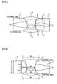
Fig. 1 is a view for explaining shapes of grooves inembodiments -
Fig. 2 is a view for explaining a cross-sectional area of internal weld metal (S1) and a cross-sectional area of external weld metal (S2) according to theembodiments -
Fig. 3 is a view for explaining positions where Charpy impact test specimens are sampled in theembodiments -
Fig. 4 is a view for explaining bead widths W1 and W2 in theembodiments - Inventors of the present invention prepared weld joints on internal and external surfaces of steel plates under various welding conditions by submerged arc welding, and investigated cross-sectional shapes of weld metals, cross-sectional areas of weld metals, and the toughness of welded heat affected zones.
- As a result of the investigation, the inventors have made a finding that by properly controlling the cross-sectional areas of internal weld metal and external weld metal corresponding to a plate thickness, a bead width on a surface of the steel plate can be increased while acquiring a sufficient penetration and hence, excellent toughness can be acquired in the welded heat affected zone on both internal and external surfaces of the steel plate. The present invention has been made by making further studies based on the acquired finding.
- In the submerged arc welding method for a steel plate according to the present invention, in welding an internal side and an external side of the steel plate, a welding condition is selected such that a sum of the cross-sectional area of internal weld metal S1 and the cross-sectional area of external weld metal S2 satisfies the formula (1) so as to prevent the occurrence of lack of penetration ;

wherein t: a plate thickness of the steel plate (mm), S1: cross-sectional area of the internal weld metal in the cross-sectional macro structure of a weld perpendicular to the welding direction excluding a cross-sectional area of a portion to be overlapped with the external weld metal after external welding (mm2), S2: a cross-sectional area of external weld metal in the cross-sectional macro structure of a weld perpendicular to the welding direction (mm2). - When the sum of the cross-sectional area of the internal weld metal (S1) and the cross-sectional area of the external weld metal (S2) is less than 0.40×t2, a penetration depth of internal welding and/or a penetration depth of the external welding are insufficient so that the internal weld metal and the external weld metal do not overlap with each other, whereby a sound weld bead cannot be obtained. The sum of the cross-sectional area of the internal weld metal (S1) and the cross-sectional area of the external weldmetal (S2) preferably falls within a range of (0.40 to 0.60)×t2
- Further, the welding condition is selected such that the cross-sectional area of the internal weld metal (S1) and the cross-sectional area of the external weld metal (S2) satisfy the formula (2) and the formula (3) so as to prevent a welding heat input from becoming excessively large;


When the cross-sectional area of the internal weld metal (S1) exceeds 0.35×t2, the welding heat input in internal welding becomes excessively large, thus giving rise to a drawback that the toughness of a welded heat affected zone is deteriorated. A preferred range of S1/t2 is 0.20 to 0.30. A sum of the cross-sectional area of the internal weld metal (S1) and the cross-sectional area of the external weld metal (S2) becomes 0.80×t2 or less from the formula (2) and the formula (3). - In the same manner, when the cross-sectional area of the external weld metal S2 exceeds 0.45×t2, the welding heat input becomes excessively large in external welding, thus giving rise to a drawback that the toughness of the welded heat affected zone is deteriorated. A preferable range of S2/t2 is 0.25 to 0.40.
- In carrying out the present invention, preliminarily, weldings are performed on specimens having the same plate thickness as that of a plate for a actual welding under various conditions to obtain the relationship between a heat input and cross-sectional area of weld metal, and a welding condition where S1 and S2 satisfy the formula (1), the formula (2) and the formula (3) is selected. It is desirable that a welding condition of high current density is applied to a preceding electrode such that the internal weld metal and the external weld metal overlap with each other.
Preferred toughness of the welded heat affected zone according to the present invention is 50J or more in terms of absorbed energy (average value) when a Charpy impact test (location of notch: FL, test temperature: -30°C, the number of tests: 3) is carried out. The toughness of welded heat affected zone is more preferably 90J or more. - Further, the present invention provides a weld joint which is manufactured by the above-mentioned welding method.
In the present invention, the cross-sectional area of the internal weld metal (S1) is defined as follows. Although external welding is carried out after carrying out internal welding, as shown inFig. 2 , a part of the internal weld metal is remelted at the time of external welding and hence, it is impossible to directly measure a cross-sectional area of weld metal formed by internal welding. Accordingly, an area of a portion of the internal weld metal excluding a portion of the internal weld overlapping with the external weld metal is measured, and this measured area is set as a cross-sectional area of the internal weld metal (S1). - Further, in addition to the above-mentioned steps, inventors of the present invention prepared an internal and external weld joint for a steel plate under various welding conditions by submerged arc welding of a steel plate, studied the relationship between a bead shape and the toughness of a welded heat affected zone, and found that by controlling a ratio between a bead width measured on a surface of the steel plate and also a bead width in the vicinity of a distal end of penetration (a position of a depth of 0.4t from a surface of the steel plate) and a plate thickness of the steel plate within a proper range, an excellent Charpy impact test result (location of notch: FL (fusion line)) can be obtained while suppressing slag inclusion.
- In the submerged arc welding method for a steel plate according to the present invention, in welding the steel plate by internal and external one layer welding, in both internal welding and external welding, a welding condition is selected such that the relationship between the plate thickness and the bead width measured on the surface of the steel plate satisfies the formula (4).

wherein, t: a plate thickness (mm), W1: a bead width measured on surfaces of the steel plate on an internal welding side and an external welding side (mm).
When the relationship between the plate thickness t and the bead width W1 measured on surfaces of the steel plate on the internal welding side and the external welding side satisfies 0. 60≤W1/t≤0.95, slag inclusion can be suppressed so that a sound weld can be obtained. - In the weld bead where the relationship between the bead width W1 and the plate thickness t becomes W1/t>0. 95, a quantity of heat applied to a base material is inevitably increased and hence, the toughness of the welded heat affected zone is deteriorated.
- On the other hand, in the weld bead where the relationship between the bead width W1 and the plate thickness t becomes 0.60>W1/t, the bead width becomes approximately uniform from the surface of the steel plate to the distal end of penetration and hence, FL takes a fusion shape substantially perpendicular to the surface of the steel plate, whereby a brittle fracture in the plate thickness direction is liable to progress thus lowering a toughness value. Further, a welding defect attributed to slag inclusion is liable to occur. A preferred range of W1/t is 0.65 to 0.90.
- Accordingly, a welding condition is selected so as to satisfy the formula (5) in addition to the condition stipulated in the formula (4), thus inclining FL at a predetermined angle or more with respect to the plate thickness direction of the steel plate.

In the formula (5), the bead width W2 measured at the position of depth of 0.4t from the surface of the steel plate where the above-mentioned bead width W1 is measured is set such that W2/t becomes 0.45 or less and hence, the bead width at a plate thickness center portion becomes narrower than the bead width at the surface of the steel plate. A preferable range of W2/t is 0.20 to 0.40. - In carrying out the present invention, preliminarily, weldings are performed on specimens having the same plate thickness as that of the steel plate of actual welding under various conditions to obtain the relationship between a heat input and a shape of fusion, and a welding condition where W1 and W2 satisfy the formula (4) and the formula (5) is selected. It is desirable that a welding condition of high current density is applied to a preceding electrode such that the internal weld metal and the external weld metal overlap with each other.
- Further, the present invention provides a weld joint manufactured by the above-mentioned welding method.
- Groove machining having a groove shape shown in
Fig. 1 was applied tosteel plates 1 for UOE steel pipes having chemical compositions shown in Table 1 and having plate thicknesses 28, 33, and 38.1mm and, thereafter, multiple-electrode submerged arc welding for internal and external one layer welding was applied to thesteel plates 1 under welding conditions shown in Table 3 thus manufacturing weld joints. Table 2 shows groove sizes. - Charpy impact test specimens (No. 4 specimens stipulated in JIS Z 3111) were sampled from the manufactured joints, and subjected to a Charpy impact test (location of notch: FL, test temperature: -30°C) in accordance with a metal material impact test method stipulated in JIS Z 2242 so as to obtain an absorbed energy (an average value obtained by carrying out the test three times).
-
Fig. 3 shows positions where theCharpy impact specimens 2 were sampled. Using theFL 5 of theweld 4 as the location of notch, each specimen was sampled such that a notch 3 is arranged parallel to the plate thickness direction, and with respect to internal welding and external welding respectively, a position 7mm below the surface of thesteel plate 1 becomes the center of theCharpy impact specimen 2. Here, the location of notch 3: FL5 was positioned such that a rate between the weld metal and the base material (welded heat affected zone) at a bottom of the notch becomes 50%-50%.
Table 4 shows the result of Charpy impact test (upper stage: an internal side, a lower stage: an external side) and an observation result of cross-sectional shape of the weld metal. In the evaluation shown in Table 4, the specimen which had no defect and whose vE-30 was 90J or more was given "⊚ : extremely good", the specimen which had no defect and whose vE-30 on an internal side and/or external side was 50J or more and less than 90J was given "○ : good", and the specimen which was defective or had vE-30 of less than 50J on an internal side or on an external side was given " × bad" . - In the present invention examples (conditions No. 1 to No. 5), by controlling a cross-sectional area of the weld metal in internal and external one layer welding, a sound weld bead having a sufficient penetration depth was formed and hence, the steel plate could acquire excellent toughness (90J or more) in the welded heat affected zone. For a reference purpose, measured values of W1/t, and W2/t with respect to a shape of fusion of the
weld metal 4 according toclaim 2 of the present invention were shown. All of the present invention examples (conditions No. 1 to No. 5) satisfied the formula (4) and the formula (5) defined inclaim 2 of the present invention. W1 and W2 were measured at the measuring positions shown inFig. 3 . - On the other hand, the sum of cross-sectional areas of weld metals in the internal and external one layer welding was small in comparison examples (conditions No. 8 and No. 9) and hence, the comparison examples did not satisfy the formula (1) defined in
claim 1 thus causing lack of penetration . - In the comparison example (condition No. 6), the cross-sectional area of the internal weld metal did not satisfy the formula (2) defined in
claim 1 and hence, the toughness of the internal welded heat affected zone was deteriorated. In the comparison example (condition No. 7), the cross-sectional area of the external weld metal did not satisfy the formula (3) defined inclaim 1 and hence, the toughness of the external welded heat affected zone was deteriorated. - Groove machining was applied to steel plates having plate thicknesses and compositions shown in Table 1 of the
embodiment 1 for forming grooves having groove shapes shown inFig. 1 and groove sizes shown in Table 2 of theembodiment 1 and, thereafter, 4-electrode submerged arc welding for internal and external one layer welding was applied to thesteel plates 1 under welding conditions shown in Table 5, thus manufacturing weld joints. - Charpy impact test specimens (No. 4 specimens stipulated in JIS Z 3111) were sampled from the manufactured joints such that a position 7mm below the surface of each of the
steel plate 1 on an internal welding side or an external welding side becomes the center of the Charpy impact specimen and were subjected to a Charpy impact test (location of notch: FL, test temperature: -30°C, the number of times that the test was carried out: 3) in accordance with a metal material impact test method stipulated in JIS Z 2242, thus obtaining an absorbed energy (an average value). Here, the location of notch 3: FL5 is positioned such that a rate between weld metal and the base material (welded heat affected zone) at a bottom of the notch becomes 50%-50%. -
Fig. 4 schematically shows positions where W1, and W2 in the shape of fusion of theweld metal 4 on an external welding side and an internal welding side were measured. - Table 6 shows the shapes of welds, the result of the Charpy impact test and the presence or non-presence of a welding defect. Table 6 also shows a measurement result of the cross-sectional shapes of weld metals S1/t2, S2/t2 and (S1+ S2) /t2. In the evaluation shown in Table 6, the specimen which had no defect and whose vE-30 was 90J or more was given "⊚ : extremely god", the specimen which had no defect and whose vE-30 on an internal side and/or external side was 50J or more and less than 90J was given "○ : good", and the specimen which was defective and had vE-30 of less than 50J on an internal side or an external side was given "× bard". The conditions No. 1 to No. 6 are the present invention examples and satisfy the formulae (1) to (3) defined in claim 1 (cross-sectional areas of weld metals in internal and external one layer welding are controlled) and hence, brought sound weld beads with a sufficient penetration depth. These present invention examples also satisfy the formulae (4) and (5) defined in
claim 2 in both internal and external one layer welding and hence, brought extremely favorable toughnesses (90J or more) in a welded heat affected zone while bringing sound beads with no welding defect. - On the other hand, although the conditions No. 7 to No. 11 satisfy the formulae (1) to (3) defined in
claim 1, the conditions No. 7 to No. 11 do not satisfy the formula (4) or (5) defined inclaim 2. Accordingly, although the conditions No. 7 to No. 11 are the present invention examples, the conditions No. 7 to No. 11 are inferior to the conditions No. 1 to No. 6 with respect to the toughness of the internal or external welded heat affected zone. To be more specific, the external welding became W1/t > 0.95 in the condition No. 7 so that the condition No. 7 did not satisfy the formula (4) defined inclaim 2, and a Charpy impact value of the external welded heat affected zone was low. In the condition No. 8, the external welding became W2/t > 0.95 so that the condition No. 8 did not satisfy the formula (5) defined inclaim 2, and a Charpy impact value of the external welded heat affected zone was low. - In the conditions No. 9 and No. 10, the internal welding became W1/t < 0.60 so that these conditions No. 9 and No. 10 did not satisfy the formula (4) defined in
claim 2, and a Charpy impact value of the internal welded heat affected zone was low. In the condition No. 11, the external welding became W1/t < 0.60 so that the condition did not satisfy the formula (4) defined inclaim 2, and a Charpy impact value of the external welded heat affected zone was low.
The condition No. 12 is a comparison example where the cross-sectional area of the external weld metal did not satisfy the formula (3) defined inclaim 1 and, further, the internal welding became W1/t > 0.95 so that condition No. 12 did not satisfy the formula (4) defined inclaim 2 whereby a Charpy impact value of the external welded heat affected zone was low. The condition No. 13 is a comparison example where a sum of a cross-sectional area of the internal weld metal and a cross-sectional area of the external weld metal did not satisfy the formula (1) defined inclaim 1 and, further, the internal welding became W1/t < 0.60 so that condition No. 13 did not satisfy the formula (4) defined inclaim 2 whereby a lack of penetration occurred. -
- 1: steel plate for UOE steel pipe
- 2: Charpy impact test specimen
- 3: location of notch
- 4: weld
- 5. BOND (also referred to as FL)
-
[Table 1] (mass%) C Si Mn P S Cu Ni Mo Nb plate thickness (mm) grade 0.04 0.16 1.57 0.011 0.002 0.02 0.01 0.16 0.03 28.0 APIX60 0.07 0.15 1.59 0.013 0.003 0.25 0.16 0.19 0.03 33.0 APIX70 0.05 0.30 1.25 0.011 0.001 0.02 0.28 0.10 0.03 38.1 APIX65 -
[Table 2] groove symbol plate thickness a (mm) b (mm) c (mm) θ1 (deg) θ2 (deg) a 28.0 9.5 7.7 10.8 70 70 b 33.0 10.0 9.5 13.5 65 65 c 38.1 11.9 10.8 15.4 65 65 -
[Table 3] condition No groove symbol classification first electrode second electrode third electrode fourth electrode welding speed (cm/min) heat input (kJ/mm) current (A) voltage (V) wire diameter (mm) current (A) voltage (V) wire diameter (mm) current (A) voltage (V) wire diameter (mm) current (A) voltage (V) wire diameter (mm) 1 a internal side 1200 38 2.4 800 40 2.4 700 42 3.2 600 42 3.2 153 5.2 external side 1200 38 2.4 800 40 2.4 700 42 3.2 600 42 3.2 125 6.3 2 b internal side 1200 38 2.4 800 40 2.4 700 42 3.2 600 42 3.2 160 5.0 external side 1200 38 2.4 800 40 2.4 700 42 3.2 600 42 3.2 115 6.9 3 b internal side 1200 35 2.4 800 38 2.4 700 40 3.2 500 40 3.2 165 4.4 external side 1200 35 2.4 800 38 2.4 700 40 3.2 500 40 3.2 125 5.8 4 c internal side 1200 38 2.4 800 40 2.4 700 42 3.2 600 42 3.2 120 6.6 external side 1200 38 2.4 800 40 2.4 700 42 3.2 600 42 3.2 80 9.9 5 c internal side 1200 38 2.4 800 40 2.4 700 42 3.2 600 42 3.2 95 8.3 external side 1200 38 2.4 800 40 2.4 700 42 3.2 600 42 3.2 90 8.8 6 a internal side 1200 38 2.4 800 40 2.4 700 45 3.2 700 45 3.2 130 6.5 external side 1200 38 2.4 800 40 2.4 700 45 3.2 700 45 3.2 140 6.0 7 a internal side 1200 38 2.4 800 40 2.4 700 45 3.2 700 45 3.2 165 5.1 external side 1200 38 2.4 800 40 2.4 700 45 3.2 700 45 3.2 115 7.3 8 b internal side 1200 38 2.4 800 40 2.4 700 42 3.2 600 42 3.2 180 4.4 external side 1200 38 2.4 800 40 2.4 700 42 3.2 600 42 3.2 130 6.1 9 c internal side 1200 38 2.4 800 40 2.4 700 42 3.2 600 42 3.2 150 5.3 external side 1200 38 2.4 800 40 2.4 700 42 3.2 600 42 3.2 110 7.2 -
[Table 4] condition No classification S1/t2 S2/t2 (S1+S2)/t2 W1/t W2/t vE-30 (J) presence/non-presence of defect evaluation classification 1 internal side 0.33 0.44 0.77 0.78 0.34 143 no defect ⊚ extremely good present invention example external side 0.88 0.36 97 2 internal side 0.23 0.32 0.55 0.64 0.29 210 no defect ⊚ : extremely good present invention example external side 0.78 0.32 177 3 internal side 0.18 0.24 0.42 0.60 0.28 200 no defect ⊚ : extremely good present invention example external side 0.70 0.30 161 4 internal side 0.23 0.42 0.65 0.66 0.27 228 no defect ⊚ : extremely good present invention example external side 0.86 0.32 132 5 internal side 0.31 0.32 0.63 0.77 0.29 177 no defect ⊚ : extremely good present invention external side 0.79 0.30 164 6 internal side 0.36* 0.38 0.74 0.89 0.37 42 no defect × : bad comparison example external side 0.85 0.36 166 7 internal side 0.29 0.46* 0.75 0.77 0.34 145 no defect × : bad comparison example external side 0.96** 0.38 31 8 internal side 0.16 0.22 0.38* 0.61 0.28 202 lack of penetration × : bad comparison example external side 0.73 0.30 151 9 internal side 0.16 0.22 0.38* 0.58** 0.25 230 lack of penetration × : bad comparison example external side 0.70 0.28 197 Note 1: symbol * indicating outside the scope of the present invention (claim 1) symbol ** indicating outside the scope of the present invention (claim 2)
Note 2: W1: bead width measured on surface of steel plate (mm) W2: bead width measured at depth of 0.4t (t plate thickness) in plate thickness direction from surface of steel plate (mm)
Note 3: vE-30(J): upper stage: test value of internal side, lower stage: test value of external side (average value of three tests) Test condition: test temperature: -30°C, location of notch: Fusion Line
Note 4: evaluation: ⊚ : extremely good, ○ : good, × : bad -
[Table 5] condition No groove symbol classification first electrode second electrode third electrode fourth electrode welding speed (cm/min) heat input (kJ/mm) current (A) voltage (V) wire diameter (mm) current (A) voltage (V) wire diameter (mm) current (A) voltage (V) wire diameter (mm) current (A) voltage M (A) (V) wire diameter (mm) 1 a internal side 1200 38 2.4 800 42 2.4 700 45 3.2 600 45 3.2 155 5.3 external side 1200 38 2.4 800 42 2.4 700 45 3.2 600 45 3.2 125 6.6 2 a internal side 1200 35 2.4 1000 40 2.4 700 42 3.2 600 42 3.2 150 5.5 external side 1200 35 2.4 1000 40 2.4 700 42 3.2 600 42 3.2 135 6.1 3 b internal side 1250 35 2.4 800 38 2.4 700 40 3.2 500 40 3.2 150 4.9 external side 1200 35 2.4 800 40 2.4 700 42 3.2 600 42 3.2 110 7.0 4 b internal side 1200 35 2.4 800 40 2.4 700 42 3.2 600 42 3.2 145 5.3 external side 1200 38 2.4 800 40 2.4 700 42 3.2 600 42 3.2 110 7.2 5 c internal side 1250 35 2.4 800 40 2.4 700 42 3.2 600 42 3.2 130 6.0 external side 1250 35 2.4 800 40 2.4 700 42 3.2 600 42 3.2 95 8.2 6 c internal side 1250 35 2.4 800 40 2.4 700 42 3.2 600 42 3.2 120 6.5 external side 1200 38 2.4 800 40 2.4 700 42 3.2 600 42 3.2 120 6.6 7 a internal side 1200 38 2.4 800 40 2.4 700 42 3.2 600 42 3.2 170 4.7 external side 1200 38 2.4 800 42 2.4 700 45 3.2 600 45 3.2 120 6.9 8 a internal side 1200 38 2.4 800 40 2.4 700 42 3.2 600 42 3.2 170 4.7 external side 1200 38 4.0 1050 40 4.0 900 42 4.0 700 42 4.0 165 5.6 9 b internal side 1250 35 2.4 1000 40 2.4 700 42 3.2 600 42 3.2 170 4.9 external side 1200 38 2.4 800 40 2.4 700 42 3.2 600 42 3.2 110 7.2 10 c internal side 1250 35 2.4 800 40 2.4 700 42 3.2 600 42 3.2 140 5.6 external side 1200 38 2.4 1000 40 2.4 700 42 3.2 600 42 3.2 95 8.9 11 a internal side 1200 38 2.4 800 42 2.4 750 45 3.2 700 45 3.2 150 5.8 external side 1200 35 2.4 750 38 2.4 700 40 3.2 500 40 3.2 165 4.3 12 b internal side 1200 38 2.4 900 45 2.4 800 45 3.2 700 45 3.2 160 5.8 external side 1200 38 2.4 900 45 2.4 800 45 3.2 700 45 3.2 90 10.2 13 b internal side 1200 35 2.4 750 42 2.4 700 42 3.2 650 42 3.2 185 4.2 external side 1200 35 2.4 750 42 2.4 700 42 3.2 650 42 3.2 170 4.6 -
[Table 6] condition No classification S1/t2 S2/t2 (S1+S2)/t2 W1/t W2/t vE-30(J) presence/non-presence of defect evaluation remarks 1 internal side 0.34 0.42 0.76 0.79 0.34 180 no defect ⊚ : extremely good present invention example external side 0.94 0.37 122 2 internal side 0.35 0.39 0.74 0.80 0.35 164 no defect ⊚ : extremely good present invention example external side 0.85 0.43 136 3 internal side 0.22 0.32 0.54 0.61 0.28 125 no defect ⊚ : extremely good present invention example external side 0.79 0.32 148 4 internal side 0.24 0.33 0.57 0.67 0.29 173 no defect ⊚ : extremely good present invention example external side 0.80 0.32 134 5 internal side 0.21 0.28 0.49 0.62 0.26 114 no defect ⊚ : extremely good present invention example external side 0.76 0.29 230 6 internal side 0.22 0.23 0.45 0.68 0.27 202 no defect ⊚ : extremely good present invention example external side 0.66 0.27 227 7 internal side 0.30 0.44 0.74 0.74 0.33 191 no defect ○ : good present invention example external side 0.97** 0.37 68 8 internal side 0.30 0.36 0.66 0.74 0.33 163 no defect ○ : good present invention example external side 0.82 0.47** 77 9 internal side 0.22 0.33 0.55 0.59** 0.28 82 no defect ○ : good present invention example external side 0.80 0.32 176 10 internal side 0.19 0.30 0.49 0.57** 0.26 79 no defect ○ : good present invention example external side 0.80 0.30 163 11 internal side 0.35 0.27 0.62 0.78 0.35 191 no defect ○ : good present invention example external side 0.58** 0.33 70 12 internal side 0.25 0.47* 0.72 0.70 0.31 110 no defect × : bad comparison example external side 0.96** 0.38 26 13 internal side 0.18 0.21 0.39* 0.59** 0.24 212 lack of penetration × : bad comparison example external side 0.72 0.27 155 Note 1: symbol* indicating outside the scope of the present invention (claim 1) symbol ** indicating outside the scope of the present invention (claim 2)
Note 2: W1: bead width measured on surface of steel plate (mm) W2: bead width measured at depth of 0.4t (t: plate thickness) in plate thickness direction from surface of steel plate (mm)
Note 3: vE-30(J): upper stage: test value of internal side, lower stage: test value of external side (average value of three tests) Test condition: test temperature: -30°C, location of notch: Fusion Line
Note 4: evaluation: ⊚ : extremely good, ○ : good, × : bad
Claims (5)
- A submerged arc welding method for a steel plate characterized in that in performing internal-and-external one layer welding on a steel plate by submerged arc welding, a sum of a cross-sectional area of internal weld metal S1 and a cross-sectional area of external weld metal S2 satisfies the formula (1), the cross-sectional area of the internal weld metal S1 satisfies the formula (2), and the cross-sectional area of the external weld metal S2 satisfies the formula (3);


wherein t: a plate thickness of the steel plate (mm), S1: a cross-sectional area of the internal weld metal (mm2) excluding a cross-sectional area of a portion of the internal weld metal overlapping with external weld metal after external welding, and Ss: a cross-sectional area of the external weld metal (mm2). - The submerged arc welding method for a steel plate according to claim 1, wherein in both the internal welding and the external welding, a bead width measured on a surface of the steel plate satisfies the formula (4), and a bead width measured at a depth of 0. 4t from the surface of the steel plate satisfies the formula (5);

wherein t: the plate thickness (mm), W1: a bead width measured on the surfaces of the steel plate on the internal welding side and the external welding side(mm),
wherein, t: the plate thickness (mm), W2: a bead width measured at a position of 0.4t in the plate thickness direction from the surfaces of the steel plate on the internal welding side and the external welding side(mm). - A weld joint manufactured by the welding method according to claim 1 or 2.
- A submerged arc welding method for a steel plate which performs internal-and-external one layer welding on a steel plate, wherein in both the internal welding and the external welding, a bead width measured on a surface of the steel plate satisfies the formula (4), and a bead width measured at a depth of 0.4t from the surface of the steel plate satisfies the formula (5);

wherein t: a plate thickness (mm), W1: a bead width measured on the surfaces of the steel plate on the internal welding side and the external welding side (mm),
wherein t: a plate thickness (mm), W2: a bead width measured at a position of 0.4t in the plate thickness direction from the surfaces of the steel plate on the internal welding side and the external welding side(mm). - A weld joint manufactured by the welding method according to claim 4.
Applications Claiming Priority (3)
| Application Number | Priority Date | Filing Date | Title |
|---|---|---|---|
| JP2009127170A JP5742090B2 (en) | 2009-05-27 | 2009-05-27 | Submerged arc welding method for steel with excellent toughness of weld heat affected zone |
| JP2009127171A JP5742091B2 (en) | 2009-05-27 | 2009-05-27 | Submerged arc welding method for steel with excellent toughness of weld heat affected zone |
| PCT/JP2009/065883 WO2010137186A1 (en) | 2009-05-27 | 2009-09-04 | Submerged arc welding method for steel plate |
Publications (3)
| Publication Number | Publication Date |
|---|---|
| EP2436472A1 true EP2436472A1 (en) | 2012-04-04 |
| EP2436472A4 EP2436472A4 (en) | 2015-05-27 |
| EP2436472B1 EP2436472B1 (en) | 2023-02-01 |
Family
ID=43222322
Family Applications (1)
| Application Number | Title | Priority Date | Filing Date |
|---|---|---|---|
| EP09845247.7A Active EP2436472B1 (en) | 2009-05-27 | 2009-09-04 | Submerged arc welding method for steel plate |
Country Status (5)
| Country | Link |
|---|---|
| US (1) | US8955554B2 (en) |
| EP (1) | EP2436472B1 (en) |
| CN (1) | CN102448655B (en) |
| RU (1) | RU2493943C2 (en) |
| WO (1) | WO2010137186A1 (en) |
Cited By (1)
| Publication number | Priority date | Publication date | Assignee | Title |
|---|---|---|---|---|
| CN105880952A (en) * | 2016-06-03 | 2016-08-24 | 合肥紫金钢管股份有限公司 | Production process of longitudinal submerged arc welded pipe for oil and gas transmission |
Families Citing this family (12)
| Publication number | Priority date | Publication date | Assignee | Title |
|---|---|---|---|---|
| JP5772977B2 (en) * | 2011-11-29 | 2015-09-02 | Jfeスチール株式会社 | Submerged arc welding method for steel sheet |
| WO2014024365A1 (en) * | 2012-08-09 | 2014-02-13 | Jfeスチール株式会社 | Submerged arc welding method, welded joint formed by said welding method, and steel tube having said welded joint |
| JP6060604B2 (en) * | 2012-10-05 | 2017-01-18 | Jfeスチール株式会社 | Submerged arc welding method |
| GB2508175B (en) * | 2012-11-22 | 2015-06-24 | Technip France | Mechanically lined pipe |
| CN103196715B (en) * | 2013-03-06 | 2016-08-03 | 中国石油天然气集团公司 | A kind of processing method of Charpy bar |
| JP5954272B2 (en) * | 2013-07-11 | 2016-07-20 | Jfeスチール株式会社 | Submerged arc welding method and welded joint manufacturing method |
| EP3095548A4 (en) * | 2014-01-17 | 2017-09-27 | Hitachi, Ltd. | Laser welding method and welded joint |
| CN106989216A (en) * | 2016-01-20 | 2017-07-28 | 浙江三花智能控制股份有限公司 | The processing method of pipe fitting body, pipe fitting and pipe fitting |
| KR101931879B1 (en) * | 2017-06-28 | 2019-03-13 | 가즈트랑스포르 에 떼끄니가즈 | Sealed membrane and method for assembling a sealed membrane |
| CN111751145A (en) * | 2020-05-19 | 2020-10-09 | 巨力索具股份有限公司 | Sampling method for alloy steel round steel butt joint |
| RU2763952C1 (en) * | 2021-02-24 | 2022-01-11 | Российская Федерация, от имени которой выступает Государственная корпорация по атомной энергии "Росатом" (Госкорпорация "Росатом") | Method of hidden arc welding of parts of different thickness |
| CN114192938A (en) * | 2021-12-21 | 2022-03-18 | 中车长江铜陵车辆有限公司 | Method for quickly identifying welding position of suspension beam after welding repair |
Family Cites Families (27)
| Publication number | Priority date | Publication date | Assignee | Title |
|---|---|---|---|---|
| JPS54122670A (en) | 1978-03-17 | 1979-09-22 | Mitsubishi Heavy Ind Ltd | Manufacture of spiral tube |
| JPS55112181A (en) * | 1979-02-23 | 1980-08-29 | Nippon Kokan Kk <Nkk> | Welding method for production of large-diameter thick-walled steel pipe |
| JPS5966978A (en) | 1982-10-12 | 1984-04-16 | Nippon Steel Corp | Multielectrode submerged arc welding method |
| DE3517015A1 (en) * | 1985-05-11 | 1986-11-13 | Fried. Krupp Gmbh, 4300 Essen | METHOD FOR ARC WELDING NITROGEN ALLOY STEELS |
| SU1274888A1 (en) * | 1985-07-17 | 1986-12-07 | Киевский Ордена Ленина Политехнический Институт Им.50-Летия Великой Октябрьской Социалистической Революции | Method of one-side arc welding |
| JPS6422469A (en) * | 1987-07-20 | 1989-01-25 | Nippon Kokan Kk | Automatic arc welding method |
| US5494209A (en) * | 1992-12-28 | 1996-02-27 | Olin Corporation | Method for the manufacture of an internally enhanced welded tubing |
| JP2650601B2 (en) * | 1993-05-20 | 1997-09-03 | 住友金属工業株式会社 | Manufacturing method of thick wall large diameter steel pipe by welding |
| JP2692542B2 (en) | 1993-09-03 | 1997-12-17 | 住友金属工業株式会社 | Pipe welding method |
| JPH10109171A (en) | 1996-10-02 | 1998-04-28 | Ishikawajima Harima Heavy Ind Co Ltd | High current density submerged arc welding method |
| RU2089363C1 (en) * | 1996-10-22 | 1997-09-10 | Шуляковский Олег Борисович | Method of welding of base structures manufactured of steel |
| JPH11138266A (en) | 1997-11-10 | 1999-05-25 | Ishikawajima Harima Heavy Ind Co Ltd | Tandem submerged arc welding method |
| DE60043151D1 (en) * | 1999-08-06 | 2009-11-26 | Sumitomo Metal Ind | WELDED TUBE MARTENSITIC STAINLESS STEEL |
| US6782921B1 (en) * | 2000-06-09 | 2004-08-31 | Nippon Steel Corporation | High-strength steel pipe excellent in formability and burst resistance |
| BRPI0411204B1 (en) * | 2003-07-21 | 2015-04-14 | Grant Prideco Lp | Tubular Component Device and Connector and Method for Soldering a Tubular Component and a Connector |
| JP4564245B2 (en) * | 2003-07-25 | 2010-10-20 | 新日本製鐵株式会社 | Super high strength welded joint with excellent low temperature cracking property of weld metal and method for producing high strength welded steel pipe |
| JP5283306B2 (en) | 2005-03-28 | 2013-09-04 | Jfeスチール株式会社 | Submerged arc welding method for steel |
| CN2887514Y (en) * | 2006-02-21 | 2007-04-11 | 中国水利水电第七工程局机电安装分局 | Welded structure of pressure water diversion steel pipe in hydropower station |
| FR2905293B1 (en) * | 2006-09-06 | 2008-11-07 | Air Liquide | WIRE, FLUX AND PROCESS FOR WELDING HIGH-NICKEL STEEL |
| BRPI0718935B1 (en) * | 2006-11-30 | 2016-08-23 | Nippon Steel & Sumitomo Metal Corp | Welded pipes for superior high strength pipe at low temperature toughness and production method thereof. |
| JP5251089B2 (en) * | 2006-12-04 | 2013-07-31 | 新日鐵住金株式会社 | Welded steel pipe for high-strength thick-walled line pipe excellent in low-temperature toughness and manufacturing method |
| CN101112733A (en) * | 2007-08-30 | 2008-01-30 | 沈阳飞机工业(集团)有限公司 | Hidden arc welding technics |
| CN101422836A (en) * | 2007-09-11 | 2009-05-06 | 大宇造船海洋株式会社 | Welding method of butt-welded joints |
| WO2009104806A1 (en) * | 2008-02-22 | 2009-08-27 | Jfeスチール株式会社 | Submerged arc welding method with multiple electrodes for steel material |
| CN101337301B (en) * | 2008-08-06 | 2011-01-05 | 武汉钢铁(集团)公司 | Submerged arc welding method of bridge steel of different intensity scale |
| US7874471B2 (en) * | 2008-12-23 | 2011-01-25 | Exxonmobil Research And Engineering Company | Butt weld and method of making using fusion and friction stir welding |
| JP5048167B2 (en) * | 2010-09-14 | 2012-10-17 | 新日本製鐵株式会社 | Thick welded steel pipe excellent in low temperature toughness, manufacturing method of thick welded steel pipe excellent in low temperature toughness, steel sheet for manufacturing thick welded steel pipe |
-
2009
- 2009-09-04 EP EP09845247.7A patent/EP2436472B1/en active Active
- 2009-09-04 WO PCT/JP2009/065883 patent/WO2010137186A1/en not_active Ceased
- 2009-09-04 US US13/321,970 patent/US8955554B2/en active Active
- 2009-09-04 RU RU2011153228/02A patent/RU2493943C2/en active
- 2009-09-04 CN CN200980159476.7A patent/CN102448655B/en active Active
Non-Patent Citations (1)
| Title |
|---|
| See references of WO2010137186A1 * |
Cited By (1)
| Publication number | Priority date | Publication date | Assignee | Title |
|---|---|---|---|---|
| CN105880952A (en) * | 2016-06-03 | 2016-08-24 | 合肥紫金钢管股份有限公司 | Production process of longitudinal submerged arc welded pipe for oil and gas transmission |
Also Published As
| Publication number | Publication date |
|---|---|
| EP2436472B1 (en) | 2023-02-01 |
| RU2493943C2 (en) | 2013-09-27 |
| CN102448655B (en) | 2015-11-25 |
| US20120325362A1 (en) | 2012-12-27 |
| US8955554B2 (en) | 2015-02-17 |
| CN102448655A (en) | 2012-05-09 |
| EP2436472A4 (en) | 2015-05-27 |
| RU2011153228A (en) | 2013-07-10 |
| WO2010137186A1 (en) | 2010-12-02 |
Similar Documents
| Publication | Publication Date | Title |
|---|---|---|
| US8955554B2 (en) | Submerged arc welding method for steel plate | |
| EP2279823B1 (en) | Welded structure comprising a large-heat-input butt welded joint having controlled hardness and controlled size of the heat affected zone for excellent brittle fracture resistance | |
| EP2174746A1 (en) | Low-Hydrogen coated electrode | |
| CN101927390A (en) | Method for welding circumferential weld between metal thin-wall clad layer and base layer of clad pipe | |
| CN102330034A (en) | X65MS steel-grade spiral welded tube for acidic corrosion environment and manufacturing method thereof | |
| EP2067566A1 (en) | Flux-cored wire for submerged arc welding of low-temperature steel and a method for welding using the same | |
| CN101100013A (en) | Method for welding circumferential weld of composite pipe of thin-wall stainless steel clad layer and carbon steel base layer | |
| EP1637270B1 (en) | Method of liquid phase diffusion bonding of metallic machine parts | |
| CN101886222A (en) | Method for manufacturing high-strength X90 steel grade spiral submerged arc welded pipe | |
| TWI882624B (en) | Single-sided submerged arc welding method and welding joint | |
| JP4998353B2 (en) | Manufacturing method of welded steel pipe | |
| EP2883643B1 (en) | Submerged arc welding method | |
| JP6201803B2 (en) | Submerged arc welds with excellent low temperature toughness | |
| JP2009214127A (en) | Submerged arc welding method for steel material | |
| JP2009233679A (en) | Submerged arc welding method of steel material | |
| EP3162489B1 (en) | Method of butt welding steel plates and butt weld joint of steel plates | |
| JP3896031B2 (en) | Manufacturing method of high strength UOE steel pipe | |
| JP5742091B2 (en) | Submerged arc welding method for steel with excellent toughness of weld heat affected zone | |
| JP6776798B2 (en) | Multi-layer submerged arc welding method | |
| JP2007268551A (en) | Multi-electrode one side submerged arc welding method | |
| JP5742090B2 (en) | Submerged arc welding method for steel with excellent toughness of weld heat affected zone | |
| JPH07290244A (en) | Welding method for clad steel pipe | |
| CN113579430B (en) | Narrow-slit submerged arc welding method suitable for medium plate wear-resistant steel | |
| JP6455210B2 (en) | UOE steel pipe with excellent low temperature toughness | |
| JP4489009B2 (en) | Bond flux for submerged arc welding |
Legal Events
| Date | Code | Title | Description |
|---|---|---|---|
| PUAI | Public reference made under article 153(3) epc to a published international application that has entered the european phase |
Free format text: ORIGINAL CODE: 0009012 |
|
| 17P | Request for examination filed |
Effective date: 20111221 |
|
| AK | Designated contracting states |
Kind code of ref document: A1 Designated state(s): AT BE BG CH CY CZ DE DK EE ES FI FR GB GR HR HU IE IS IT LI LT LU LV MC MK MT NL NO PL PT RO SE SI SK SM TR |
|
| DAX | Request for extension of the european patent (deleted) | ||
| RA4 | Supplementary search report drawn up and despatched (corrected) |
Effective date: 20150428 |
|
| RIC1 | Information provided on ipc code assigned before grant |
Ipc: B23K 101/06 20060101ALI20150421BHEP Ipc: B23K 9/025 20060101ALI20150421BHEP Ipc: B23K 9/18 20060101AFI20150421BHEP |
|
| STAA | Information on the status of an ep patent application or granted ep patent |
Free format text: STATUS: EXAMINATION IS IN PROGRESS |
|
| 17Q | First examination report despatched |
Effective date: 20180504 |
|
| REG | Reference to a national code |
Ref country code: DE Ref legal event code: R079 Ref document number: 602009064750 Country of ref document: DE Free format text: PREVIOUS MAIN CLASS: B23K0009180000 Ipc: B23K0101100000 |
|
| RIC1 | Information provided on ipc code assigned before grant |
Ipc: B23K 9/18 20060101ALI20220221BHEP Ipc: B23K 9/025 20060101ALI20220221BHEP Ipc: B23K 101/06 20060101ALI20220221BHEP Ipc: B23K 33/00 20060101ALI20220221BHEP Ipc: B23K 103/04 20060101ALI20220221BHEP Ipc: B23K 101/10 20060101AFI20220221BHEP |
|
| GRAP | Despatch of communication of intention to grant a patent |
Free format text: ORIGINAL CODE: EPIDOSNIGR1 |
|
| STAA | Information on the status of an ep patent application or granted ep patent |
Free format text: STATUS: GRANT OF PATENT IS INTENDED |
|
| INTG | Intention to grant announced |
Effective date: 20220831 |
|
| GRAS | Grant fee paid |
Free format text: ORIGINAL CODE: EPIDOSNIGR3 |
|
| GRAA | (expected) grant |
Free format text: ORIGINAL CODE: 0009210 |
|
| STAA | Information on the status of an ep patent application or granted ep patent |
Free format text: STATUS: THE PATENT HAS BEEN GRANTED |
|
| AK | Designated contracting states |
Kind code of ref document: B1 Designated state(s): AT BE BG CH CY CZ DE DK EE ES FI FR GB GR HR HU IE IS IT LI LT LU LV MC MK MT NL NO PL PT RO SE SI SK SM TR |
|
| REG | Reference to a national code |
Ref country code: GB Ref legal event code: FG4D |
|
| REG | Reference to a national code |
Ref country code: CH Ref legal event code: EP Ref country code: AT Ref legal event code: REF Ref document number: 1546797 Country of ref document: AT Kind code of ref document: T Effective date: 20230215 |
|
| REG | Reference to a national code |
Ref country code: DE Ref legal event code: R096 Ref document number: 602009064750 Country of ref document: DE |
|
| REG | Reference to a national code |
Ref country code: IE Ref legal event code: FG4D |
|
| REG | Reference to a national code |
Ref country code: LT Ref legal event code: MG9D |
|
| REG | Reference to a national code |
Ref country code: NL Ref legal event code: MP Effective date: 20230201 |
|
| REG | Reference to a national code |
Ref country code: AT Ref legal event code: MK05 Ref document number: 1546797 Country of ref document: AT Kind code of ref document: T Effective date: 20230201 |
|
| PG25 | Lapsed in a contracting state [announced via postgrant information from national office to epo] |
Ref country code: PT Free format text: LAPSE BECAUSE OF FAILURE TO SUBMIT A TRANSLATION OF THE DESCRIPTION OR TO PAY THE FEE WITHIN THE PRESCRIBED TIME-LIMIT Effective date: 20230601 Ref country code: NO Free format text: LAPSE BECAUSE OF FAILURE TO SUBMIT A TRANSLATION OF THE DESCRIPTION OR TO PAY THE FEE WITHIN THE PRESCRIBED TIME-LIMIT Effective date: 20230501 Ref country code: NL Free format text: LAPSE BECAUSE OF FAILURE TO SUBMIT A TRANSLATION OF THE DESCRIPTION OR TO PAY THE FEE WITHIN THE PRESCRIBED TIME-LIMIT Effective date: 20230201 Ref country code: LV Free format text: LAPSE BECAUSE OF FAILURE TO SUBMIT A TRANSLATION OF THE DESCRIPTION OR TO PAY THE FEE WITHIN THE PRESCRIBED TIME-LIMIT Effective date: 20230201 Ref country code: LT Free format text: LAPSE BECAUSE OF FAILURE TO SUBMIT A TRANSLATION OF THE DESCRIPTION OR TO PAY THE FEE WITHIN THE PRESCRIBED TIME-LIMIT Effective date: 20230201 Ref country code: HR Free format text: LAPSE BECAUSE OF FAILURE TO SUBMIT A TRANSLATION OF THE DESCRIPTION OR TO PAY THE FEE WITHIN THE PRESCRIBED TIME-LIMIT Effective date: 20230201 Ref country code: ES Free format text: LAPSE BECAUSE OF FAILURE TO SUBMIT A TRANSLATION OF THE DESCRIPTION OR TO PAY THE FEE WITHIN THE PRESCRIBED TIME-LIMIT Effective date: 20230201 Ref country code: AT Free format text: LAPSE BECAUSE OF FAILURE TO SUBMIT A TRANSLATION OF THE DESCRIPTION OR TO PAY THE FEE WITHIN THE PRESCRIBED TIME-LIMIT Effective date: 20230201 |
|
| PG25 | Lapsed in a contracting state [announced via postgrant information from national office to epo] |
Ref country code: SE Free format text: LAPSE BECAUSE OF FAILURE TO SUBMIT A TRANSLATION OF THE DESCRIPTION OR TO PAY THE FEE WITHIN THE PRESCRIBED TIME-LIMIT Effective date: 20230201 Ref country code: PL Free format text: LAPSE BECAUSE OF FAILURE TO SUBMIT A TRANSLATION OF THE DESCRIPTION OR TO PAY THE FEE WITHIN THE PRESCRIBED TIME-LIMIT Effective date: 20230201 Ref country code: IS Free format text: LAPSE BECAUSE OF FAILURE TO SUBMIT A TRANSLATION OF THE DESCRIPTION OR TO PAY THE FEE WITHIN THE PRESCRIBED TIME-LIMIT Effective date: 20230601 Ref country code: GR Free format text: LAPSE BECAUSE OF FAILURE TO SUBMIT A TRANSLATION OF THE DESCRIPTION OR TO PAY THE FEE WITHIN THE PRESCRIBED TIME-LIMIT Effective date: 20230502 Ref country code: FI Free format text: LAPSE BECAUSE OF FAILURE TO SUBMIT A TRANSLATION OF THE DESCRIPTION OR TO PAY THE FEE WITHIN THE PRESCRIBED TIME-LIMIT Effective date: 20230201 |
|
| PG25 | Lapsed in a contracting state [announced via postgrant information from national office to epo] |
Ref country code: SM Free format text: LAPSE BECAUSE OF FAILURE TO SUBMIT A TRANSLATION OF THE DESCRIPTION OR TO PAY THE FEE WITHIN THE PRESCRIBED TIME-LIMIT Effective date: 20230201 Ref country code: RO Free format text: LAPSE BECAUSE OF FAILURE TO SUBMIT A TRANSLATION OF THE DESCRIPTION OR TO PAY THE FEE WITHIN THE PRESCRIBED TIME-LIMIT Effective date: 20230201 Ref country code: EE Free format text: LAPSE BECAUSE OF FAILURE TO SUBMIT A TRANSLATION OF THE DESCRIPTION OR TO PAY THE FEE WITHIN THE PRESCRIBED TIME-LIMIT Effective date: 20230201 Ref country code: DK Free format text: LAPSE BECAUSE OF FAILURE TO SUBMIT A TRANSLATION OF THE DESCRIPTION OR TO PAY THE FEE WITHIN THE PRESCRIBED TIME-LIMIT Effective date: 20230201 Ref country code: CZ Free format text: LAPSE BECAUSE OF FAILURE TO SUBMIT A TRANSLATION OF THE DESCRIPTION OR TO PAY THE FEE WITHIN THE PRESCRIBED TIME-LIMIT Effective date: 20230201 |
|
| REG | Reference to a national code |
Ref country code: DE Ref legal event code: R097 Ref document number: 602009064750 Country of ref document: DE |
|
| PG25 | Lapsed in a contracting state [announced via postgrant information from national office to epo] |
Ref country code: SK Free format text: LAPSE BECAUSE OF FAILURE TO SUBMIT A TRANSLATION OF THE DESCRIPTION OR TO PAY THE FEE WITHIN THE PRESCRIBED TIME-LIMIT Effective date: 20230201 |
|
| PLBE | No opposition filed within time limit |
Free format text: ORIGINAL CODE: 0009261 |
|
| STAA | Information on the status of an ep patent application or granted ep patent |
Free format text: STATUS: NO OPPOSITION FILED WITHIN TIME LIMIT |
|
| 26N | No opposition filed |
Effective date: 20231103 |
|
| PG25 | Lapsed in a contracting state [announced via postgrant information from national office to epo] |
Ref country code: SI Free format text: LAPSE BECAUSE OF FAILURE TO SUBMIT A TRANSLATION OF THE DESCRIPTION OR TO PAY THE FEE WITHIN THE PRESCRIBED TIME-LIMIT Effective date: 20230201 |
|
| REG | Reference to a national code |
Ref country code: CH Ref legal event code: PL |
|
| PG25 | Lapsed in a contracting state [announced via postgrant information from national office to epo] |
Ref country code: LU Free format text: LAPSE BECAUSE OF NON-PAYMENT OF DUE FEES Effective date: 20230904 |
|
| REG | Reference to a national code |
Ref country code: BE Ref legal event code: MM Effective date: 20230930 |
|
| PG25 | Lapsed in a contracting state [announced via postgrant information from national office to epo] |
Ref country code: LU Free format text: LAPSE BECAUSE OF NON-PAYMENT OF DUE FEES Effective date: 20230904 Ref country code: MC Free format text: LAPSE BECAUSE OF FAILURE TO SUBMIT A TRANSLATION OF THE DESCRIPTION OR TO PAY THE FEE WITHIN THE PRESCRIBED TIME-LIMIT Effective date: 20230201 |
|
| REG | Reference to a national code |
Ref country code: IE Ref legal event code: MM4A |
|
| PG25 | Lapsed in a contracting state [announced via postgrant information from national office to epo] |
Ref country code: IE Free format text: LAPSE BECAUSE OF NON-PAYMENT OF DUE FEES Effective date: 20230904 |
|
| PG25 | Lapsed in a contracting state [announced via postgrant information from national office to epo] |
Ref country code: CH Free format text: LAPSE BECAUSE OF NON-PAYMENT OF DUE FEES Effective date: 20230930 |
|
| PG25 | Lapsed in a contracting state [announced via postgrant information from national office to epo] |
Ref country code: IE Free format text: LAPSE BECAUSE OF NON-PAYMENT OF DUE FEES Effective date: 20230904 Ref country code: CH Free format text: LAPSE BECAUSE OF NON-PAYMENT OF DUE FEES Effective date: 20230930 |
|
| PG25 | Lapsed in a contracting state [announced via postgrant information from national office to epo] |
Ref country code: BE Free format text: LAPSE BECAUSE OF NON-PAYMENT OF DUE FEES Effective date: 20230930 |
|
| PG25 | Lapsed in a contracting state [announced via postgrant information from national office to epo] |
Ref country code: BG Free format text: LAPSE BECAUSE OF FAILURE TO SUBMIT A TRANSLATION OF THE DESCRIPTION OR TO PAY THE FEE WITHIN THE PRESCRIBED TIME-LIMIT Effective date: 20230201 |
|
| PG25 | Lapsed in a contracting state [announced via postgrant information from national office to epo] |
Ref country code: BG Free format text: LAPSE BECAUSE OF FAILURE TO SUBMIT A TRANSLATION OF THE DESCRIPTION OR TO PAY THE FEE WITHIN THE PRESCRIBED TIME-LIMIT Effective date: 20230201 |
|
| PG25 | Lapsed in a contracting state [announced via postgrant information from national office to epo] |
Ref country code: HU Free format text: LAPSE BECAUSE OF FAILURE TO SUBMIT A TRANSLATION OF THE DESCRIPTION OR TO PAY THE FEE WITHIN THE PRESCRIBED TIME-LIMIT; INVALID AB INITIO Effective date: 20090904 |
|
| PG25 | Lapsed in a contracting state [announced via postgrant information from national office to epo] |
Ref country code: CY Free format text: LAPSE BECAUSE OF FAILURE TO SUBMIT A TRANSLATION OF THE DESCRIPTION OR TO PAY THE FEE WITHIN THE PRESCRIBED TIME-LIMIT; INVALID AB INITIO Effective date: 20090904 |
|
| PGFP | Annual fee paid to national office [announced via postgrant information from national office to epo] |
Ref country code: DE Payment date: 20250730 Year of fee payment: 17 |
|
| PGFP | Annual fee paid to national office [announced via postgrant information from national office to epo] |
Ref country code: IT Payment date: 20250825 Year of fee payment: 17 |
|
| PGFP | Annual fee paid to national office [announced via postgrant information from national office to epo] |
Ref country code: GB Payment date: 20250731 Year of fee payment: 17 |
|
| PGFP | Annual fee paid to national office [announced via postgrant information from national office to epo] |
Ref country code: FR Payment date: 20250808 Year of fee payment: 17 |
|
| PG25 | Lapsed in a contracting state [announced via postgrant information from national office to epo] |
Ref country code: TR Free format text: LAPSE BECAUSE OF FAILURE TO SUBMIT A TRANSLATION OF THE DESCRIPTION OR TO PAY THE FEE WITHIN THE PRESCRIBED TIME-LIMIT Effective date: 20230201 |